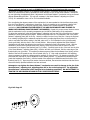
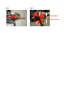
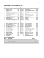
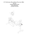
1
1 The following pages are to educate dealers/service technicians on the basic maintenance and service for the SCHWINNIndoor Cycling bikes. By following the enclosed instructions and maintenance schedule, you will extend the life of your bikes and help ensure the equipment will withstand hours of use in your home/facility. ENCLOSED YOU WILL FIND: 1. 2. 3. 4. 5. 6. 7. 8. 9. 10. Recommended Tools and Lubes Assembly Instructions Recommended Stock Levels Recommended Repairs on moving parts Daily and weekly maintenance schedule Monthly maintenance Troubleshooting Exploded Drawing / Parts List SCHWINNProduct Warranty Warranty procedures If you have additional questions on service, please contact your authorized dealer or call us at 800-785-9073. RECOMMENDED TOOLS AND LUBES FOR ASSEMBLY, MAINTENANCE AND REPAIRS TOOLS : Torque wrench-showing lbf/in. or ibf/ft. Crank Puller (must use insert plug below for ISIS BB) ISIS Insert Plug for Crank Puller, M12 x 1.0 Bottom Bracket tool Pedal Wrench BMX Freewheel tool PART NUMBER 74523 71699 71715 71717 71695 74556 Smart Release™ Adjusting Tool 71709 LUBES: SCHWINNFit-Tech Silicone Lube Equipment Polish SchwinnQuick Shot Citrus Chain Wax Citrus Foam Degreaser 72016 73200 72012 72013 72011 MISCELLANEOUS TOOLS : 3-mm Allen wrench (water bottle cage) 4-mm Allen wrench (chain guard’s) 10- mm socket or wrench 11- mm wrench 13 -mm socket or wrench 14- mm socket or wrench 8mm Allen Key for 3/8” socket driver 15- mm socket or wrench Adjustable wrench 2 ASSEMBLY I NSTRUCTIONS FOR THE 2006 SCHWINN INDOOR CYCLING E VOLUTION/E VOLUTION SR BIKES 1. 2. 3. 4. Prior to assembly, apply a coat of Equipment Polish (#73200) to all painted surfaces of the Schwinn Bike. Apply Quick Shot (#72012) to the threads on the pedals (#42) and to the threads of stainless steel bolts (#39) Mount the front and rear stabilizer (A&B) to the frame with Allen bolt (#39) and washer (#50) on each side of stabilizer. Use the nut (#51) on the bottom and tighten with a 13-mm socket wrench. Be certain to use grease on bolts (#39). Use a torque wrench (#74523) and a 8mm Allen Key, tighten each crank bolt to 480 lbf/in (40 lbf/ft) 5. Remove brake pads (#48) with 4-mm Allen wrench and saturate them with Fit-Tech Silicone Lube (#72016). Then let air dry for 45 minutes before putting pads back on. 6. Check the flywheel to ensure that it is lined up evenly with the frame. The chain should be snug, but not so tight that it pops or makes a grinding noise. With the chain properly tensioned, the flywheel should turn when rocking the crank arms. 7. Use the pedal wrench (#71695) to attach the pedal to the crank arms. The pedal marked with an “R” on the spindle has right-hand threads and tightens clockwise into the right crank arm (#2). The pedal marked with an “L” on the spindle has left-hand threads and tightens counter-clockwise into the left crank arm (#56). Apply Fit-Tech Silicone lube (#72016) to the seat adjustment tubes (#26&27) and the handlebar tube (#25). 8. 9. 10. Level off the saddle to the seat post bracket (#27) using the 14-mm wrench and lock the bracket into the seat post (#26) using the pop pin assembly (#44). Insert the handlebar pop pin into the frame and secure with an adjustable wrench. 11. Insert handlebar into frame. 12. Using 3mm Allen Key supplied, mount both water bottle cages to the sides of the forks. 13. Level the bike by screwing in or out the levelers #49, once level tighten leveler nut #38. 14. Test ride the bike, them make any appropriate adjustments. 15. To break in the resistance mechanism, we suggest that you tighten the resistance adjustment knob to fully tight and leave it overnight. The following day you may release all the pressure from the adjustment knob and the resistance mechanism should be broken in and ready for use. RECOMMENDED STOCK LEVELS FOR THE SCHWINNEVOLUTION™ AND EVOLUTION™-SR BIKES SCHWINNEvolution Maintenance Kit: For every 10 S CHWINNIndoor cycling bikes you may want to stock: TOOLS: P ART NUMBER Crank Puller ISIS Insert Plug for Crank Puller, M12 x 1.0 Bracket Tool Bottom Pedal Wrench SCHWINNFit-Tech Silicone Lube SCHWINNQuick Shot Bottom Bracket (ISIS Overdrive) Pair Brake Pads 71699 71715 71717 71695 72016 72012 84990 92874 Evolution Chain ½”x3/32”, 106L Seat 95120 93092 QTY. 1 1 2 1 1 1 1 1 3 1 1 3 Pop Pin Assembly (Double Lead) Plastic Sleeve Square Nuts Water Bottle Cages 84994 84966 98022 84998 1 1 5 3 These are the tools and lubes that the NAUTILUS support team uses to properly assemble, maintain and repair the S CHWINNIndoor Cycling bikes. Whether you will perform all of the functions “in house” or through a service contract with an authorized NAUTILUS dealer, we strongly recommend that you keep each of these items in stock. The items in the maintenance kits will provide your facility with the tools and SCHWINNparts to keep your bikes in top condition. RECOMMENDED REPAIRS ON COMMON MOVING P ARTS ON THE SCHWINN INDOOR CYCLING BIKES Recommended Tools & Lubes Tools needed 1. 2. 3. 4. 5. 6. 7. 8. 9. 40. 11. 12. 13. 14. 14. 16. 17. 17. Torque wrench w/ 8-mm Allen Key socket: used to tighten the crank bolts of crank arms to 480 lbf/in. (Torque wrench part #74523) Pedal wrench: Has 15-mm and 9/16" wrench to tighten and loosen pedals (part #71695) Crank puller: needed to take off right and left crank arms (part #71699) ISIS Insert Plug for Crank Puller, M12 x 1.0 (part# 71715). Bottom bracket tool for ISIS Overdrive BB: used to take out bottom bracket from frame (part #71717) Adjustable wrench: used to tighten or loosen the pop pin assembly from frame. 17-mm wrench: used to adjust the inside axle nuts closest to the flywheel bearings 15-mm wrench: used to loosen the outside axle nut on each side of the flywheel when tightening chain 14-mm wrench: used to tighten the nuts of the seat bracket 13-mm wrench: needed during assembly for the front and back stabilizers nuts and bolts 11-mm wrench: used to tighten the larger bolt of the brake assembly 10-mm wrench: used to adjust chain tensioner bolts during chain tightening, transport wheel nut and bolt, and front nut of the resistance assembly when centering brake pads. 8-mm wrench: goes to the smaller resistance knob nylon nut (older models) and smaller brake assembly bolt 7-mm wrench: used to loosen guide rod nut when replacing guide rod springs 5-mm Allen wrench: Used to tighten the bolts on Evolution stabilizers. 4-mm Allen wrench: used to loosen the bolt of the brake pads and the Allen chain guard screws (newer models) 3-mm Allen wrench: used for the screws of the water bottle cages Smart Release™ adjusting tool: High quality tool specifically designed for use with the new adjustable Smart Release™ mechanism. (2002+ model bikes and newer). (Part$ 71719). Lubes needed 1. SCHWINNFit-Tech Silicone Spray: recommended for the brake pads and all moving parts I.E., handle bar post, seat post & slide, pop-pins, resistance knob etc. (part #72016) 2. 3. SCHWINNEquipment Polish: recommended on a damp cloth when wiping down the frame after use (part #73200) SCHWINNCitrus Chain Wax: recommended to lubricate the chain through the rear hole in the chain guard as the flywheel is rotating (part #72013) 4 4. SCHWINNQuick Shot: recommended for the threads of stabilizer bolts and pedals before tightening to crank arms (part #72012) H OW TO CHANGE A CHAIN IN THE 2006 S CHWINNINDOOR CYCLING P ROTM/ELITETM/EVOLUTION/SR BIKES Tools needed 1. 14-mm Wrench or Socket 2. 10mm Wrench 3. 4-mm Allen wrench Procedure Caution: Never touch the chain with a cloth our your hand while the chain is moving. Use the 4mm Allen wrench to remove the 3 screws of the outer chain guard and take off the guard. The outer guard slides off easiest with the right pedal at 10 o'clock. Use the 14-mm wrench or socket to remove each axle nut from the flywheel axle. Remove the chain tensioner bolts with a 10-mm wrench, which will allow you to take off each chain adjustment bracket. Carefully lower the flywheel to the bottom of the frame. You can now take the old chain off and put the new chain on. Carefully lift the flywheel back into place on the frame. Reinstall each bracket to the axle and tighten each bolt evenly so the flywheel stays aligned with the frame. Adjust the chain tension by locating the point where the chain is tightest during one revolution of the crank. Check the tension; you should be able to move the chain up/down a total of 3/8” (in either direction), at the tightest point. Once the chain is adjusted, reattach the outside chain guard using the three 4-mm Allen head screws. Make sure the chain is properly lubricated prior to testing the bike. Listen for any grinding, which could be caused by the chain tension being too tight or the flywheel being out of alignment with the frame. Make any final adjustments. TM TM HOW TO C HANGE A B OTTOM B RACKET IN THE 2006 SCHWINNI NDOOR C YCLING PRO /E LITE /EVOLUTION /SR BIKES Tools needed 1. Bottom Bracket Tool 2. Pedal Wrench 3. Crank Puller 4. ISIS Insert Plug for Crank Puller, M12 x 1.0 5. 6. 7. 8. 9. 10. Torque Wrench 14-mm Wrench 10-mm Wrench 4-mm Allen Wrench 3/8” drive Socket Wrench Adjustable Wrench 11. ISIS Insert Plug for Crank Puller, M12 x 1.0 11. 8-mm Allen Key wrench Procedure (Part-#71717) (#71695) (#71699) 17175 (#74523) w/8mm Allen key socket (#71717) 5 Caution: Never touch the chain with a cloth our your hand while the chain is moving. Use the 4mm Allen wrench to remove the 3 screws of the outer chain guard and take off the guard. Use the 14-mm wrench to loosen each of the axle nuts. Use the 10-mm wrench to turn each of the chain tensioner bolts to the left 2 half turns. This will loosen the chain tension enough to facilitate removal later. Carefully take the chain off the right crank sprocket. Remove each crank bolt using the 8mm Allen Key wrench. Be certain to remove the crank bolt washer from the crank arm before proceeding with the next step. Insert the ISIS Insert plug into the BB spindle, thread into spindle using 8mm Allen Key until it is flush with the end of the spindle. Screw the crank puller into the right crank arm snug the crank puller to the crank using an adjustable wrench, turn the arm of the puller clock-wise until the crank slides off (repeat this step for the left crank arm). Use your Bottom Bracket tool for ISIS Overdrive (#71717) with you adjustable wrench to remove the “non-drive side” BB cup first. (The non-drive side BB is right hand threaded). Turn the wrench counter clock-wise (left) to remove the cup. Repeat this step on the “drive side” of the bike (sprocket side), this time turning the wrench clock-wise (right) to loosen the cup. (This cup is REVERSE threaded.) Before putting the new bottom bracket into the frame, it is a good idea to inspect the threads for damage and to apply blue LocTite to the cups for best results. Install the new BB by threading the cartridge in from the drive side first. Carefully thread the BB in by hand to ensure you do not cross the threads (remember the drive side threads are REVERSE, so turn the BB counter clock-wise to tighten.) Use your torque wrench and BB tool to apply 570 lbf/in. (48 lbf/ft.). Repeat this step on the non-drive side, remember the non-drive side BB threads are standard and tighten in the clock-wise direction. Torque non-drive side BB cup to 570 lbf/in. with the torque wrench. Replace the crank arms and torque crank bolts to 480 lbf/in . Carefully rotate the chain back onto the sprocket and retighten the chain tensioner bolts. Be sure to tighten each bolt evenly so the flywheel stays aligned with the frame. Reinstall the chain guard, make sure the chain tension and flywheel alignment are correct, (for instructions on this, see the procedure on how to change a chain above.) H OW TO CHANGE THE LEFT CRANK ARM OF THE SCHWINNINDOOR CYCLING BIKE Tools needed 1. Pedal Wrench 2. 8-mm Allen wrench (SCHWINNPart -#71695) (#74523) w/ 8mm Allen Key 3. Torque Wrench Socket 4. Crank Puller (#71699) 5. Adjustable Wrench 6. 3/8” Socket Wrench 7. ISIS Insert Plug for Crank Puller, M12 x 1.0 (#71715) Procedure Remove the left pedal using the 15-mm side of the pedal wrench, by turning wrench (clockwise) toward the back of the bike. Remove the crank bolt using the 8mm Allen Key wrench, be careful to also remove the washer from inside the crank arm before proceeding to the next step. Insert the ISIS plug into the spindle, using the 8mm Allen Key wrench, thread the plug into the spindle until it is flush with the spindle end. Thread the crank puller into the left crank arm, snug crank puller down using an adjustable wrench. Rotate the handle of the puller clockwise until the left crank comes off. Apply a liberal amount of grease to the spliced ends of the ISIS Overdrive spindle, it is MANDATORY that these splines be well greased before installing the crank arm. Place the new left crank onto the bottom bracket. Grease the threads of the crank bolt and tighten the crank bolt to 480 lbf/. Re-lube the threads of the left pedal and tighten turning the pedal wrench toward the front of the bike (counterclockwise). H OW TO ADJUST THE NEW ADJUSTABLE SMART RELEASE ™ MECHANISM Tools needed 1. Smart Release™ Adjusting Tool Procedure (SCHWINN Part -#71709) 6 Only a mechanic trained to work on SCHWINN® IC bicycles should perform this procedure. Adjustments to release pressure of the patented Smart Release™ mechanism should only be performed to restore the mechanism to factory specifications. Never attempt to lock out the Smart Release™ mechanism by over tightening the adjustment plate. Adjustments to the Smart Release™ mechanism can be performed without disassembling the bike. The only tool necessary is the Smart Release™ adjusting tool (Part # 71709): It is advisable to have a 45 or 50 LB dumbbell available. Prior to adjusting the release pressure of the mechanism it is recommended to ride the bike and purposely force the Smart Release™ mechanism to break free. Do this by pedaling up to a moderate cadence with little or no resistance on the flywheel, applying back pressure to the cranks sufficient to release the mechanism (ONLY PERFORM THIS PROCESS IF YOU ARE FAMILIAR WITH AND TRAINED TO WORK ON SCHWINN® SMART RELEASE™MECHANISM). Repeat this process several times to ensure that the mechanism is up to operating temperature and to feel the initial setting of the mechanism. To adjust the mechanism, insert the Smart Release™ adjusting tool from the front of the bike into the space between the chain guard and the flywheel. Rotate the flywheel until the 7-mm-diameter hole in the Smart Release™ adjusting plate (#66 in the Fig. 1 below) is visible from the front of the bike. Secure the flywheel from rotating by tightening the resistance mechanism until it provides significant force on the flywheel. In order to reproduce the factory setting in the field; place a 45- or 50 LB dumbbell on the right side pedal (chain guard side) with the crank in the 9 o’clock position. When properly adjusted the Smart Release™ mechanism should break free allowing the crank arm to rotate down under this amount of load. With the dumbbell in place and the flywheel locked from rotating, Insert the tool such that the bend in the tool corresponds to the shape of the flywheel (see Fig. 2 below). Carefully insert the pin of the tool into the hole of the Smart Release™ adjusting plate (#66). Hold the tool with your left-hand, hold the outer edge of the flywheel with your right hand. To increase the release pressure (make the breakaway force higher) pull the handle of the tool UP toward the top of the flywheel (see Fig. 3). Only small movements in the adjusting ring are necessary to effect the release pressure, generally no more than 45 – 50 degrees movement of the tool handle are required for proper adjustment of the release pressure. To decrease the release pressure (make the breakaway force lower), push the handle of the adjusting tool DOWN toward the bottom of the flywheel (see Fig. 3). Once the proper tension has been achieved, the technician should test ride the bike to ensure the factory specified resistance has been achieved. Attempts to over tighten the Smart Release™ mechanism can result in damage to the pin of the Smart Release™ adjusting tool, adjusting plate #66 or the conical spring #64. The adjustable Smart Release™ mechanism is NOT designed to be locked up completely. DO NOT ATTEMPT TO TIGHTEN THE MECHANISM BEYOND FACTORY SPECIFIED SETTINGS! Fig 1 Ref. Page 15 70 54 66 67 53 55 54 64 37 7 Fig. 2. Fig. 3 Up to tighten Down to loosen 8 MAINTENANCE D AILY MAINTENANCE Every day at the end of your last Indoor Cycling Class, have each member release the brake resistance on the S CHWINN® bike so the brake pads do not contact the flywheel, and wipe down the bike using SCHWINN® equipment polish (#73200) with a clean, damp cloth. This will help clean and protect your SCHWINN® bike. We also suggest you remove the handlebars from the head tube to allow the handlebar tube and sleeve to dry properly. (Note: Never operate the bike without brake resistance! Always increase the brake resistance prior to use. After each class, wipe down your SCHWINN ® bike with a clean cloth. Pay special attention to the hardware areas where perspiration could settle. Example: handlebars. It is also a good idea to reapply Schwinn Fit-Tech Silicone Spray to the Handle bar and Seat post sliders to keep them running smooth in the sleeves. WEEKLY MAINTENANCE Inspect your S CHWINN® Indoor cycling bike for loose parts, nuts, bolts, etc. Pay special attention to the brake assembly and both the seat and handlebar pop-pins. This action will help prolong the service life of your SCHWINN® Indoor Cycling bike. Lubricate the chain using Schwinn Citrus Chain Wax or other chain lubricant containing Teflon®. MONTHLY MAINTENANCE CHECK Check the chain to ensure that it is properly adjusted. Move the crank arms back and forth; if there is more than ¼” movement in the chain before the flywheel turns, you will need to tighten the chain. To do this, simply loosen the flywheel axle nuts (# 21) then rotate the chain tensioner bolts (#27) clockwise by a ½ turn. NOTE: Make sure that you adjust both sides equally so that the flywheel remains in alignment with the frame. Check the crank bolts with a torque wrench (#74523) to ensure that the bolts remain tight but torque does not exceed 480 lbf/. Ensure that both pedals are secured and properly attached to the crank arms. Crossed threads can be caused by allowing your clients to change their own pedals. Trained personnel must do pedal changes. Crossed threads do not qualify for warranty replacement. Check all handlebar and seat pop-pins to ensure that they are tight and operating smoothly. WARNING Use extreme care when servicing the Schwinn® Indoor cycling bike with the chain guard removed. If your fingers or other parts of the body come into contact with moving parts inside the bike, amputation or other serious injury may occur. Prior to commencing any maintenance on the chain drive, familiarize yourself with all moving parts. Never leave a Schwinn® bike unattended with the chain guard removed. 9 TROUBLESHOOTING A loud squealing sound from the brake pads – Using a 4-mm Allen Wrench, take off the bolt and spring then slide pads out of the assembly. There is no need to remove the shroud from the Evolution model in order to remove the pads. If the pads look glossy or shiny, you will need to rough up the surface with a wire brush. After doing so, the pads need to be saturated with S CHWINN ® Fit-Tech Silicone (#72016). Tighten the bolt and spring to the pads only finger-tight. This will create longer life for the brake pads on your bike. Tight resistance assembly – (The brake pads touching the flywheel with the resistance knob turned all the way to the left). Turn the resistance knob all the way to the right and let sit over night. This will relax the guide rod springs allowing space between the pads and the flywheel. Brake pads off-center - Use a 10-mm wrench to loosen the nylon nut (# 95456) on the front of the bike. This will allow you adjust the brake assembly until the brakes are evenly spaced from the flywheel. Retighten the nylon nut using moderate torque. Play in the Chain - (chain is too loose). Use a 14-mm wrench or socket to loosen each axle nut of the flywheel. Use a 10-mm wrench and turn each chain tensioner bolt ¼ turn to the right. Get on the bike and check for any play in the chain by rocking back and forth on the pedals. Once the pedals and the flywheel are moving as one, tighten the axle nuts on the flywheel. Make sure the flywheel remains in alignment with the frame. Grind in the Chain – (chain is too tight or flywheel is out of alignment with frame). Loosen each axle nut using a 14-mm wrench. Adjust the 10-mm chain tensioner bolts to align the flywheel with the frame. Make sure that the chain tension is adjusted properly without being too tight. Adjust the chain tension by locating the point where the chain is tightest during one revolution of the crank. Check the tension; you should be able to move the chain up/down a total of 3/8” (in either direction). Ensure that the chain is properly lubricated, then test-ride the bike. Bike wobbling or uneven while riding – Check the foot levelers on the bottom of the stabilizers. Adjust until the bike is square on the floor. Securing the leveler nut will prevent leveler from loosening. Tight fit on the handlebar or seat post – Ensure that the handlebar/seat post extension tube and frame sleeves are both clean and lubricated with SCHWINN® Fit-Tech Lube. If fit remains tight, try switching the handlebar or seat post with one from another bike. If this does not fix the problem order new sleeve (#84966 for IC bikes, #8001 for Evolution bikes.) Ordering Parts An authorized dealer, distributor, parts & service provider may order replacement parts through Nautilus Service Representative at 1-800-785-9073 10 2006 SCHWINN IC EVOLUTION® BIKE EXPLODED D RAWING 11 2006 SCHWINN® IC EVOLUTION® BIKE P ARTS LIST 1 FRAME 84985 36 PLASTIC BALL RING 80004 2 CHAINGUARD (INNER) 84986 37 REAR STABILIZER 84984 3 CHAINGUARD (OUTER) 84982 38 HEX NUT FOR LEVELING FEET 3/8 80016 4 SHROUD (RIGHT) 80011 39 STAINLESS HEX HEAD BOLT M8X1.25X50L 80030 5 SHROUD (LEFT) 80010 40 FRONT STABILIZER 6 RUBBER RING FOR OUTER CHAINGUARD 80003 41 BOLT TRANSPORT WHL M8X1.25X45L SS 80028 7 STAINLESS STEEL AXLE NUT 3/8X26TX11T 80022 42 PEDALS 9/16" 95129 8 CHAIN ADJUST BRACKET (LEFT) 84987 43 FRAME PLUG FOR BRAKE ASSM. 92206 9 SLEEVE FOR FRAME 80001 44 T-HANDLE POP PIN DOUBLE LEAD 84994 10 STAINLESS CHAIN TEN. BOLT M6X1.0X60L 84988 45 SEAT, 7777-1, BLACK 92202 11 12 BOTTLE HOLDER CHAIN ADJUST BRACKET (RIGHT) 80012 84989 46 47 YELLOW PLASTIC BUSHING SET OF 2 SQUARE NUT 92204 98022 13 RUBBER FRAME GUARD 80014 48 BRAKE PADS 92874 14 STAINLESS SELF-TAPPING SCREW M5X12L 80040 49 LEVELER FOOT 84995 16 PROTECTIVE PLASTIC STICKER (B) 80041 50 WASHER 19 X 8.5 X 1MM SS 94526 17 PROTECTIVE PLASTIC STICKER (A) 80042 51 SCREW NUT M8 X 1.25 SS 80049 18 MACHINE SCREW M5X.08X12L SS 84957 52 TRANSPORTATION WHEEL 92210 19 EMERGENCY BRAKE LEVER 80009 53 CHAIN 106L 1/2X3/32" 80043 20 B.B. SET, OVERDRIVE W/BOLTS 68X113L 84990 54 FLYWHEEL COMPLETE SET 84996 21 STAINLESS WASHER 16 X 6.5 X1 95431 55 HUB SHELL PLASTIC COVER 92451 22 RIGHT CRANK W/SPOCKET, ISIS M12 80034 56 SPOCKET 16t (BLACK) 84997 23 LEFT CRANK ARM , ISIS 80035 57 SPROCKET WASHER 95457 24 STAINLESS HEX HEAD BOLT M6X1.0X12L 80029 58 LOCK NUT 95450 25 HANDLEBAR BLACK TEXTURED 84991 60 AXLE SET 95125 26 SEAT POST, STAINLESS 84992 61 BADGE SCHWINN LOGO 33MM 80047 27 SEAT ADJUSTMENT BRACKET 84993 63 CRANK BOLT - 1EA M12 80044 28 SLEEVE FOR SEAT SLIDER 80002 66 BOTTLE CAGE BOLT M5X.8 X16L 95428 29 SEAT RETAINING PIN 80006 67 BOTTLE CAGE 84998 30 RETAINING PIN COVER 80013 68 RUBBER FRAME GUARD STRIP 84999 31 RESISTANCE ASSEMBLY 80008 69 BADGE SCHWINN LOGO 40MM 80048 32 TENSION ADJUSTING KNOB 80017 33 TENSION KNOB RING 80005 34 ROD CARRIER 80007 35 NUT FOR RES. ASSM. M6X1.0 SS 80015 Indoor Cycling Optional Accessories DWG # DESCRIPTION 84983 PART # TRIPLE LINK PEDAL SYSTEM 95150 IC/Evo. TECH MANUAL 2004 84951 CHAINGUARD WARNING STICKER SHEET OF 12 92215 PLASTIC SHIM SHEET OF 12 92217 DECAL SET 2003/2204 Evolution 80045 12 2006 SCHWINN® IC EVOLUTION ® SR BIKE EXPLODED DRAWING 13 2006 SCHWINN® IC EVOLUTION® SR BIKE P ARTS LIST DWG # 1 DESCRIPTION PART # DWG # DESCRIPTION PART # FRAME 84985 36 PLASTIC BALL RING 80004 2 3 CHAINGUARD (INNER) CHAINGUARD (OUTER) 84986 84982 37 38 REAR STABILIZER HEX NUT FOR LEVELING FEET 3/8 84984 80016 4 5 6 SHROUD (RIGHT) SHROUD (LEFT) RUBBER RING FOR OUTER CHAINGUARD 80011 80010 80003 39 40 41 STAINLESS HEX HEAD BOLT M8X1.25X50L 80030 FRONT STABILIZER 84983 BOLT TRANSPORT WHL M8X1.25X45L SS 80028 7 8 STAINLESS STEEL AXLE NUT 3/8X26TX11T 80022 CHAIN ADJUST BRACKET (LEFT) 84987 42 43 PEDALS 9/16" FRAME PLUG FOR BRAKE ASSM. 95129 92206 9 10 SLEEVE FOR FRAME STAINLESS CHAIN TEN. BOLT M6X1.0X60L 80001 84988 44 45 T-HANDLE POP PIN DOUBLE LEAD SEAT, 7777-1, RED 84994 92202 11 12 BOTTLE HOLDER CHAIN ADJUST BRACKET (RIGHT) 80012 84989 46 47 YELLOW PLA STIC BUSHING SET OF 2 SQUARE NUT 92204 98022 13 14 16 RUBBER FRAME GUARD 80014 STAINLESS SELF-TAPPING SCREW M5X12L 80040 PROTECTIVE PLASTIC STICKER (B) 80041 48 49 50 BRAKE PADS LEVELER FOOT WASHER 19 X 8.5 X 1MM SS 92874 84995 94526 17 18 PROTECTIVE PLASTIC STICKER (A) MACHINE SCREW M5X.08X12L SS 80042 84957 51 52 SCREW NUT M8 X 1.25 SS TRANSPORTATION WHEEL 80049 92210 19 20 EMERGENCY BRAKE LEVER B.B. SET, OVERDRIVE W/BOLTS 68X113L 80009 84990 53 54 CHAIN 106L 1/2X3/32" FLYWHEEL COMPLETE SET 80043 84996 21 22 STAINLESS WASHER 16 X 6.5 X1 RIGHT CRANK W/SPOCKET, ISIS M12 95431 80034 55 56 FLANGED HUB LOCK NUT BEARING RETAINER RING 92214 92458 23 24 LEFT CRANK ARM , ISIS STAINLESS HEX HEAD BOLT M6X1.0X12L 80035 80029 57 58 HUB SHELL PLASTIC COVER INNER ADJ SR PLATE 92451 92452 25 26 27 HANDLEBAR BLACK TEXTURED SEAT POST, STAINLESS SEAT ADJUSTMENT BRACKET 84991 84992 84993 59 60 61 CONICAL SPRING INTERFACING PLATE TO BRAKE PADS SR BRAKE PAD SET, WHITE U.H.P. 92208 92453 92213 28 29 SLEEVE FOR SEAT SLIDER SEAT RETAINING PIN 80002 80006 62 63 HUB SPOCKET W/BEARING CRANK BOLT - 1EA M12 98419 80044 30 31 RETAINING PIN COVER RESISTANCE ASSEMBLY 80013 80008 64 65 AXLE SET BADGE SCHWINN LOGO 33MM 98414 80047 32 33 34 35 TENSION ADJUSTING KNOB TENSION KNOB RING ROD CARRIER NUT FOR RES. ASSM. M6X1.0 SS 80017 80005 80007 80015 66 67 68 69 BOTTLE CAGE BOLT M5X.8 X16L BOTTLE CAGE RUBBER FRAME GUARD STRIP BADGE SCHWINN LOGO 40MM 95428 84998 84999 80048 Indoor Cycling Optional Accessories DWG # DESCRIPTION PART # TRIPLE LINK PEDAL SYSTEM 95150 IC/Evo. TECH MANUAL 2004 84951 CHAINGUARD WARNING STICKER SHEET OF 12 92215 PLASTIC SHIM SHEET OF 12 92217 DECAL SET 2003/2204 Evolution-SR 80046 14 NAUTILUS INC LIMITED WARRANTY All Nautilus products are warranted to the original purchaser (end-user) to be free from defects in materials and workmanship. Product repairs that are related to, or identified as, the result of normal user wear are not covered by this warranty. TIME P ERIOD: Warranty coverage extends to the original purchaser (end-user) from the date of original purchase and while owned by the original retail purchaser: The IC Pro and IC Elite products sold for and used in a commercial or institutional setting are covered for: 2 years for parts and 15 years for the structural frame, from the date of original purchase and while owned by the original purchaser (end-user). The IC Evolution and Evolution SR products sold and used in a commercial setting are covered for: 3 years for parts and 15 years for the structural frame, from the date of original purchase and while owned by the original purchaser (end-user). THIS W ARRANTY D OES NOT COVER : 1. Any component on original equipment, which carries a separate consumer warranty provided by the component part’s supplier/manufacturer. 2. Normal wear and tear (please see the definition of “Wear Items” below). 3. Any damage, failure or loss caused by accident, misuse, neglect, abuse, improper assembly, improper maintenance, use of an improper or unauthorized replacement part, or failure to follow instructions or warnings in Owner’s Manual. 4. Use of products in a manner for which they were not designed or intended to be of use. 5. Use of any product in other than a home or residential setting, unless otherwise noted in the Owner’s Manual. Wear Items are parts/components that might need to be replaced due to normal use during the life of the product. User-life for wear items will vary depending on uncontrolled parameters (i.e., placement environment, frequency of use, type of user, scheduled maintenance, etc.). Wear items vary for each product but will include, and not be limited to: computer overlays, grips, belts, drive-train components, brake pads, pedals, pedal straps, toe clips, upholstery, and bearings, etc. A defect in materials and/or workmanship is best described as a problem related to structural failure, weakness, or deficiency in manufacturing quality. These are factors controlled through the product development, production and quality control process. A true defect in materials and/or workmanship will usually be recognized within a short period of initial product use. SUPPORT P ARAMETERS * * An authorized NAUTILUS dealer or service facility will perform warranty service (unless otherwise noted). An original, dated “Proof of Purchase” must be provided. Transportation to and from the authorized NAUTILUS dealer is the responsibility of the purchaser. NAUTILUS has the option, at its sole discretion, of either repairing or replacing, at no charge, any product requiring warranty service, or repaying an amount equal to the purchase price of the affected product. 15 * NAUTILUS is not responsible for dealer labor charges for component changeovers when a frame is replaced or for installing replacement or repaired parts (unless verified for labor warranty coverage). * If you elect to repai r a product or replace a part yourself, use the services of someone other than an authorized NAUTILUS dealer or service provider, or if you use a replacement part not supplied by NAUTILUS, the product warranty is voided and the NAUTILUS will not be liable for any damages, failure or loss caused by such improper replacement, repair or service. (PARTS) WARRANTY R EPLACEMENT P ROCEDURES Commercial fitness facilities and direct purchase customers have two warranty claim options available. Both can be used to confirm warranty coverage and reimbursement of applicable costs associated with warranty issues. LIMITATIONS: The foregoing warranties are in lieu of and exclude all other warranties not expressly set forth herein, whether express or implied by operation of law or otherwise, including but not limited to any implied warranties of merchantability or fitness. NAUTILUS shall in no event be liable for incidental or consequential loss, damages or expenses in connection with exercise products. NAUTILUS’ S liability hereunder is expressly limited to the replacement of goods not complying with this warranty or, at its election, to the repayment of an amount equal to the purchase price of the exercise equipment product in question. Some states do not permit the exclusion or limitation of implied warranties or consequential damages so the preceding limitations may not apply to you. This warranty gives you specific legal rights and you may also have other rights, which may vary from state to state. Information concerning warranty policies, procedures, and limitations can be found in all each product’s owner’s manual or determined by contacting an authorized service representative. Contact Information (Domestic) Nautilus GSA GSA Toll Free Direct 1-800-785-9073 Fax: 1-330-405-1289