1
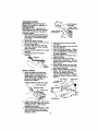
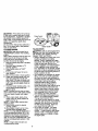
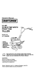
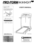
Owner's Manual
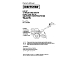
14 INCH TINE WIDTH
REAR TINE WITH
COUNTER ROTATING TINES
TILLER
Model No,
917.293470
• Safety
• Assembly
• Operation
• Maintenance
• Espa._ol
• Repair Parts
differently
from
previously
built engines.
Before operates
you start the enThis
product
has
a low emission
engine which
gine, read and understand this Owner's Manual.
CAUTION:
Read and follow all Safety
Rules and Instructions before
operating this equipment.
Sears, Roebuck
and Co., Hoffman
Estates,
Visit our Craftsman website:www.sears.com/craftsman
II 60179
Safety Rules ......................................... 2
Warranty ............................................... 2
Product Specifications.......................... 4
Assembly.............................................. 5
Operation.............................................. 8
Maintenance Schedule ...................... 13
Maintenance....................................... 13
Service and Adjustments .................... 15
Storage ............................................... 19
Troubleshooting................................. 20
IllustratedParts List ............................ 42
Pads Ordering ..................... Back Cover
LIMITED ONE YEAR WARRANTY ON CRAFTSMAN TILLER
Forone (t) year from date of pumhase, when this CraftsmanTiller is maintained,
lubricated,and tuned up accordingto the operatingand maintenanceinstructionsin
the owne¢s manual,Sears will repairfree of charge any defectin matedal or workmanship.
ThisWarranty does not cover:.
• Expandableitemswhichbecome wornduring normaluse, such as tines, spark
plugs,air cleaners and belts.
• Repairs necessary because of operatorabuse or negligence,includingbent
crankshaftsand the failure to maintainthe equipmentaccordingto the instructions
containedin the owner's manual.
• If this CraftsmanTilleris used for commercialor rentalpurposes,this Warranty
appliesfor onlythirty(30) days from the date of purchase.
Warrantyservice is availableby returningthe craftsmanpower mower to the nearest
seam servicecentar/departmentin the unitedstates.This warrantyapplies only while
thisproductis in use in the united states.
This Warrantygives you specificlegal rights,and you may also have other rightswhich
varyfrom stateto state.
SEARS, ROEBUCKAND CO., D/817WA, HOFFMAN ESTATES,IL 60179
IMPORTANT: This cuttingmachine is capableof amputatinghandsand feet and
throwingobjects.Failureto observe the following safety instructionscould resultin
serious injuryor death.
TRAINING
• Disengageall clutchesand shift into
neutral before startingthe engine
• Read the Owner'sManual carefully.Be
(motor).
thoroughlyfamiliar with the controls
• Do not operate the equipment without
and the proper use of the equipment.
wearing adequate outer garments.
Know how to stop the unitand disenWear footwear that willimprovetooting
gage the controlsquickly.
on slipperysurfaces.
• Never allow childrento operate the
• Handle fuel withcare; it is highly
equipment. Never allowadults to
flammable.
operate the equipmentwithoutproper
• Use an approvedfuel container.
instruction.
• Never add fuel to a runningengine or
• Keep the area of operationclear of all
hot engine.
persons, padiculadysmall children,
• Fill fuel tank outdoorswithextreme
and pats.
care. Never fillfuel tank indoors.
PREPARATION
• Replace gasoline cap securelyand
• Thoroughlyinspectthe area where the
clean up spilledfuel before restarting.
equipmentis to be used and remove all • Use extensioncordsand receptacles
as specifiedby the manufacturerfor all
foreign objects.
unitswith electricdrive motorsor
2 electricstartingmotors.
• Never attempt to make any adjustments
while the engine (motor) is running
(except where specifically recommended by manufacturer),
OPERATION
• Do not put hands or feet near or under
rotating pads.
• Exercise extreme caution when
operating on or crossing gravel drives,
walks, or roads. Stay alert for hidden
hazards or traffic. Do not carry passengere.
• After striking a foreign object, stop the
engine (motor), remove the wire from
the spark plug, thoroughly inspect the
tiller for any damage, and repair the
damage before restarting and operating the tiller.
• Exercise caution to avoid slipping or
falling.
• If the unit should start to vibrate
abnormally, stop the engine (motor)
and check immediately for the cause.
Vibration is generally a warning of
trouble.
• Stop the engine (motor) when leaving
the operating position.
• Take all possible precautions when
leaving the machine unattended.
Disengage the tines, shift into neutral,
and stop the engine.
• Before cleaning, repairing, or inspect.
ing, shut off the engine and make
certain all moving parts have stopped.
Disconnect the spark plug wire, and
keep the wire away from the plug to
prevent accidental starting. Disconnect
the cord on electric motom.
• Do not run the engine indoors; exhaust
fumes are dangerous.
• Never operate the tiller without proper
guards, plates, or other safety protective devices in place,
• Keep children and pets away.
• Do not overload the machine capacity
by attempting to till too deep at too fast
a rate.
• Never operate the machine at high
speeds on slippery surfaces. Look
behind and use care when backing.
• Never allow bystanders near the unit.
• Use only attachments and accessories
approved by the manufacturer of the
tiller.
• Never operate the tiller without good
visibility or light.
• Be careful when tilling in hard ground.
The tines may catch in the ground and
propel the tiller forward. If this occurs,
let go of the handlebars and do not
restrain the machine.
MAINTENANCE
AND STORAGE
• Keep machine, attachments, and
accessories in safe working condition.
• Check shear pins, engine mounting
bolts, and other bolts at frequent
intervals for proper tightness to be sure
the equipment is in safe working
condition.
• Never store the machine with fuel in the
fuel tank inside a building where
ignition sources are present, such as
hot water and space heaters, clothes
dryers, and the like. Allow the engine to
cool before storing in any enclosure.
• Always refer to the operator's guide
instructions for important details if the
tiller is to be stored for an extended
period.
ALook for this symbol to point out
important safety precautions. It means
CAUTION!fl BECOME ALERTll! YOUR
SAFETY IS INVOLVED.
ACAUTION: Always disconnect spark
plug wire and place wire where it cannot
contact spark plug in order to prevent
accidental starting when setting up,
transporting, adjusting or making repairs.
AWARNING: Engine exhaust, some of its
constituents, and certain vehicle components contain or emit chemicals known to
the State of California to cause cancer
and birth defects or other reproductive
harm.
3
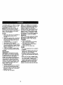
PRODUCT
SPECIFICATIONS
GASOLINE
3 QUARTS
CAPACITY:
UNLEADED
REGULAR
OIL(API-SF-SJ): SAE30
CAPACITY:
20OZ.) (ABOVE
32°F)
SAE
5W-30
(BELOW
32°F)
SPARK
PLUG:
CHAMPION
GAP:,030")
RJtgLMOR
J19LM
CONGRATULATIONS
onyourpurchase
ofa Sears
Tiller.Ithasbeendesigned,
engineered
and manufacturedto give
you the best possibledependabilityand
performance.
Shouldyou expedence any problemsyou
cannoteasily remedy, please contacta
Sears or other qualifiedService Center.
We have competent,well-trainedtechnicians and the propertoolsto service or
repair this unit.
Please read and retainthis manual.The
instructionswillenable you to assemble
and maintainyour tiller properly.Always
observethe =SAFETYRULES".
Yournew tiller has been assembledat the
factory withexceptionof those parts left
unassembledfor shippingpurposes. To
ensuresate and properoperationof your
tillerall parts and hardwareyou assemble mustbe tightenedsecurely.Use
the correcttools as necessaryto insure
proper tightness.
CUSTOMER RESPONSIBILITIES
• Read and observethe safety rules.
• Followa regularschedule in maintaining, caring for and usingyour tiller.
• Followthe instructionsunder the
"Customer Responsibilities"and
"Storage"sectionsof this Owner's
Manual,
_,WARNING: This unitis equippedwith
an intemal combustionengine and
shouldnot be used on or near any
unimprovedforest-covered, brushcoveredor grass covered land unlessthe
engine'sexhaust system is equippedwith
a spark arrestermeeting applicablelocal
or state laws (if any). If a sparkarrester is
used, it shouldbe maintainedin effective
workingorder by the operator.
In the state of Californiathe above is
requiredby law (Section4442 of the
Calitomia Public Resources Code).
Other states may have similarlaws.
Federal lawsapply on federal lands. A
spark arresterfor the muffleris available
throughyour nearest Sears service
center (See REPAIR PARTSsectionof
this manual).
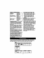
These accessorieswere availablewhen the tillerwas purchased. They are also
availableat mostSears Retail outlets and Service Centers. Most Sears Stores can
order repair parts for you when you providethe model numberof yourtiller.
ENGINE
ISP_mKPLUal UU_Lm
TILLER
I MRtqL'rBt I
PERFORMANCE
FURROW OPENER
¢
111LLER MAJNTENA_ICE
mT
4
_SC_
I B,mm_o_. I s'rJ_mLr_.RI
Your new tiller has been assembled at the
factory with exception of those pads left
unassembled for shipping purposes. To
ensure safe and proper operation of your
tiller al! parts and hardware you assemble
must be tightened securely. Use the
correct tools as necessary to insure
proper tightness.
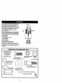
TOOLS
REQUIRED
FRONT
E
RIGHT
LEFT
FOR ASSEMBLY
A socket wrench set will make assembly
easier. Standard wrench sizes are listed.
(1) Utility knife
(1) Wire cutter
(1) Tire pressure gauge
(1) Screwdriver
(1) Pair of pliers
(1) 9/16" wrench
OPERATOR'S
POSITION
OPERATOR'S
POSITION
When right or left hand is mentioned in
this manual, it means when you are in the
operating position (standing behind tiller
handles).
CONTENTS
(2) Handle
OF HARDWARE
(1) Center Locknut
3/8-16 UNC
Locks
(1) Carriage Bolt
3/8-16
(1) Hairpin
PACK
UNC x 1 Gr. 5
(1) Cable Clip
Clips
(1) Pivot Bolt
3/8-16 UNC Grade 5
, (1) FlatWasher
13/32 x 1 x 11 Ga.
(2) Shear Pins & Clips
O
(1) Handle Lock Lever
"_
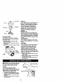
UNPACKING CARTON
_I_CAUTION: 8e carefulof exposed
staples when handlingor disposingof
cartoning matedaL
IMPORTANT: When unpackingand
assemblingtiller,be carefulof exposed
staples when handlingor disposingof
cartoning metedal.
1. While holdinghandle assembly,cut
cable ties securinghandle assembly
to top frame. Let handle assembly
rest on tiller.
2. Remove top frame of carton.
3. Slowly ease handle assembly up and
place on top of carton.
4. Cut down dght hand front and right
hand rear comers of carton,lay side
cartonwall down.
5. Remove packing material from handle
aasemb_y.
6. Separate shift rod from handle
assembly.
"UP" Position
old
Loosen Handle Lock
Lever to Move
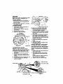
4. Insertpivotbolt in frontpart of plate
and tighten.
5. Cut down remainingcomers of carton
and lay panelsfiat.
6. Lower the handle assembly. Tighten
nut on cardage bolt so handle moves
with some resistance. This willallow
for easier adjustment.
7. Place flat washer on threaded end of
handle lock lever.
8. Insert handle lock lever through
handle base and gearcase. Screw in
handle lock lever just enoughto hold
lever in place.
9. Insertsecond handle lock (with teeth
inward) in the slot of the handle base
(justinside of washer).
tO.Raise handle assemblyto highest
positionand securelytighten handle
lock lever by rotatingclockwise.
Leaving handle assemblyin highest
positionwill make it easier to connect
shiftrod.
le
mbly
INSTALL HANDLE
1. Insertone handle lock (with teeth
facing outward) in gearcase notch.
(Applygrease on smoothside of
handle lock to aid in keeping lock in
place until handle assembly is
lowered into position.)
VIEWED
• Flat Washer
Handle Lock
FROM R.H. SIDE OFTILLER
Gearcase Notch
Handle Lock
x
2. Grasp handleassembly. Hold in "up"
position. Be sure handle lock remains
in gearcase notch. Slide handle
assembly into position.
3. Rotate handle assemblydown. insert
rear cardage boltfirst,with head of
bolton L.H. side of tiller and loosely
assemble Iocknut.
6
'Z
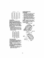
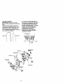
INSERT CABLE CLIP
• Insert plastic cable clip into hole on the
back of handle column. Push cables
into clip,
Hairpir
Shift Rod
Shift Lever
Indicator
Handle Column
Cables
Cable Clip
CONNECT SHIFT ROD
1. Insert end of shift rod farthest from
bend into hole of shift lever indicator.
2. Insert hairpin clip through hole of shift
rod to secure with bend of clip on right
side.
[_
Attach this End To shift
REMOVETILLER
FROM CRATE
1. Adjust handle assemby to lowest
position. Be sure lock lever iF tightened securely,
2, Make sure shift lever indicator is in "N"
(neutral) position,
3, Tilt tiller forward by lifting handle.
Separate cardboard cover from
leveling shield.
4. Rotate tiller handle to the right and
pull tiller out of carton,
Shift Rod
Lever tndicator
CHECKTIRE
PRESSURE
The tires on your unit were overinflated at
the factory for shipping purposes, Correct
and equal tire pressure is important for
best tilling performance.
• Reduce tire pressure to 20 PSI.
HANDLE
HEIGHT
• Handle height may be adjusted to
better suit operator. (See "TO ADJUST
HANDLE HEIGHT" in the Service and
Adjustments section of this manual).
7
Thesesymbolsmayappear
onyourTilleror inliterature
supplied
withtheproduct.
Leamandunderstand
theirmeaning.
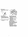
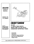
KNOWYOURTILLER
READ THIS OWNER'S MANUAL AND SAFETY RULES BEFORE OPERATING YOUR
TILLER.
Compare the illustrations with your tiller to familiarize yourself with the location of
various controls and adjustments. Save this manual for future reference.
TLLII_
FNR&
FORWARD
NEUTRAL
Rk_._SE
CNJTION
_w_m
Eq_tE
_
0<,
ENGINE
c+T
FAST
Throttle Control
Sh_ Lever
Drive Control Bar
Shift Lever Indicator
Recoil
Starter
Handle
MEETS ANSI SAFETY REQUIREMENTS
Our tillersconformto the safety standardsof the Amedcan NationalStandardsInstitute.
LEVELING SHIELD - Levels tilled soil.
SHIFT LEVER o Used to shift transmission
gears.
SHIFT LEVER INDICATOR - Shows
which gear the transmission is in.
RECOIL STARTER HANDLE - Used to
start the engine.
DRIVE CONTROL BAR - Used to engage
tines.
DEPTH STAKE - Controls depth at which
tiller will dig.
OUTER SIDE SHIELD - Adjustable to
protect small plants from being boded.
THROTTLE CONTROL - Used to control
engine speed.
8
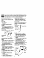
HOWTO
The operation of any tiller can result in foreign objects thrown into the eyes,
which can result in severe eye damage. Always wear safety glasses or eye
shields before starting your tiller and while tilling. We recommend a wide
vision safety mask over spectacles or standard safety glasses.
HARD TO SHIFT GEARS
USEYOURTILLER
• Briefly engage drive control bar and
release or rock tiller forward and
backward until are able to shift gears.
DEPTH STAKE
The depth stake can be raised or lowered
to allow you more versatile tilling and
cultivating, or to more easily transport
your tiller.
Know how to operate all controls before
adding fuel and oil or attempting to start
engine.
STOPPING
TINES AND DRIVE
1. Release drive control bar to stop
movement,
2. Move shift lever to "N" (neutral)
position.
ENGINE
• Move throttle control to "STOP" position. If equipped with stop switch, move
switch to "STOP" position.
NOTE= Never use choke to stop engine.
Shallowest Tilling
(Cultivating)
Deeptest Tilling_
Depth Stake _--
Drive Control Bar
"ENGAGED" Position
J
ShiffLever
TILLING
1. Release depth stake pin. Pull the
depth stake up for increased tilling
depth. Place depth stake pin in hole
of depth stake to lock in position.
2. Place shift lever indicator in till
position.
3. Hold the drive control bar against the
handle to start tilling movement. Tines
and wheels will both turn.
4. Move throttle control to "FAST"
position for deep tilling. To cultivate,
throttle control can be set at any
desired speed, depending on how fast
or slow you wish to cultivate.
IMPORTANT: Always release drive
control bar before moving shift lever into
another position.
Dnve Contml Bar
"DISENGAGED"
Poslr_n
Throttle Contml
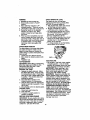
TINE OPERATION
DRIVE
"_ Transport Position
-WITHWHEEL
• Always release drive control bar before
moving shift lever into another position,
• Tine movement is achieved by moving
shift lever to (_) till position and
engaging drive control bar.
FORWARD - WHEELS ONLY/TINES
STOPPED
• Release drive control bar and move
shift lever indicator to "F" (forward)
position. Engage ddve control bar and
tiller will move forward.
REVERSE - WHEELS ONLY/TINES
STOPPED
1. DO NOT STAND DIRECTLY BEHIND
TILLER.
2. Release the drive control bar.
3. Move throttle control to "SLOW"
position.
4. Move shift lever indicator to =R"
(reverse) position.
5. Hold drive control bar against the
handle to start tiller movement.
Depth Stake Pin
"RELEASED" Position
"Locked"
Position
"B"
Side Shield
g
I'A"
TURNING
I. Release the drive controlbar.
2. Move throttlecontrolto "SLOW"
position.
3. Place shift lever indicatorin "F"
(forward) position. Tines willnot turn.
4. Lifthandle to raise tines out of ground.
5. Swingthe handle in the opposite
directionyou wish to turn, being
carefulto keep feet and legs away
from tines.
6. When you have completedyour tamaround, release the drive controlbar
and lower handle. Place shift lever in
(till)positionand move throttlecontrol
to desired speed. To begin tilling,
hold ddve controlbar againstthe
handle.
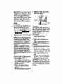
CHECK ENGINE OIL LEVEL ,
The engine in your unit has been
shipped, from the factory, already filled
with SAE 30 summer weight oil.
1. With engine level, clean area around
oil filler plug and remove plug.
2. Engine oil should be to point of
overflowing when engine is level.
• For approximate capacity see =PRODUCT SPECIFICATIONS" on page 4 of
this manual. All oil must meet A.P.I.
Service Classification SF-SJ.
• For cold weather operation you should
change oil for easier starting (See oil
viscosity chart in the Maintenance
section of this manual).
• To change engine oil, see the Maintenance section in this manual.
OUTER SIDE SHIELDS
The back edges of the outerside shields
are slottedso that the shieldscan be
raised for deep tillingand loweredfor
shallow tillingto protectsmall plantsfrom
being buried.
1, Loosennut "A"in slotand nut=B_.
2. Move shieldto desired position(both
sides).
3. Retightennuts.
ADD GASOLINE
TOTRANSPORT
• Fill fuel tank. Use fresh, clean, regular
_I,CAUTION: Beforeliftingor transporting,
unleaded gasoline. (Use of leaded
allowtiller engine and mufflerto cool.
gasoline will increase carbon and lead
Disconnectspark plug wire. Drain
oxide deposits and reduce valve life.)
gasolinefrom fuel tank.
IMPORTANT: When operating in temAROUND THE YARD
peratures below 32°F(0°C), use fresh,
I. Release the depth stake pin. Move
clean, winter grade gasoline to help
the depthstake down to the top hole
insure good cold weather starting.
for transportingthe tiller. Place depth
A, WARNING: Experience indicates that
stake pinin hole of depthstake to lock alcohol blended fuels (called gesohol or
in position. This preventstines from
using ethanol or methanol) can attract
scuffing the ground,
moisture which leads to separation and
2. Place shiftlever indicatorin "F"
formation of acids during storage. Acidic
gas can damage the fuel system of an
(forward) positionfor transporting.
3. Hold the drive controlbar againstthe
engine while in storage. To avoid engine
handle to start tillermovement. Tines
problems, the fuel system should be
will not tam.
emptied before storage of 30 days or
4. Move throttlecontrolto desired speed. longer. Drain the gas tank, start the
AROUND TOWN
engine and let it run until the fuel lines
and carburetor are empty. Use fresh fuel
1. Disconnectspark plug wire,
next season. See Storage section of this
2. Drain fuel tank.
manual for additional information. Never
3. Transport in updghtpositionto
use engine or carburetor cleaner prodpreventoil leakage.
ucts in the fuel tank or permanent
BEFORE STARTING ENGINE
damage may occur.
IMPORTANT: Be very carefulnot to allow
dirt to enter the engine when checkingor
addingoil or fuel. Use clean oil and fuel
and store in approved,clean, covered
containers, use clean fill funnels.
10
ACAUTION:
Fill to within 1/2 inch of top
of fuel tank to prevent spills and to allow
for fuel expansion. If gasoline is accidentally spilled, move machine away from
area of spill. Avoid creating any source of
ignition until gasoline vapors have
disappeared.
Do not overfill. Wipe off any spilled oil or
fuel. Do not store, spill or use gasoline
near an open flame.
TO START ENGINE
_CAUTION:
Keep drive control bar in
"DISENGAGED" position when starting
engine.
When starting engine for the first time or if
engine has run out of fuel, it will take
extra pulls of the recoil starter to move
fuel from the tank to the engine.
1. Make sure spark plug wire is properly
connected.
2. Move shift lever indicator to "N"
(neutral) position.
3. Place throttle control in "FAST"
position.
4, Turn fuel shut-off valve 1/4 turn to
open position.
5, Move choke control to choke position.
6, Grasp recoil starter handle with one
hand and grasp tiller handle with
other hand. Pull rope out slowly until
engine reaches start of compression
cycle (rope will pull slightly harder at
this point).
7. Pull recoil starter handle quickly. Do
not let starter handle snap back
against starter.
NOTE: If engine fires but does not start,
move choke control to half choke position.
Pull recoil starter handle until engine
starts.
8. When engine starts, slowly move
choke control to "RUN" position as
engine warms up.
NOTE: A warm engine requires less
choking to start.
9. Move throttle control to desired
running position.
10.Allow engine to warm up for a few
minutes before engaging tines.
NOTE: If at a high altitude (3000 feet) or
in cold temperatures (below 32°F), the
carburetor fuel mixture may need to be
adjusted for best engine performance.
See "TO ADJUST CARBURETOR" in the
Service and Adjustments section of this
manual.
NOTE: If engine does not start, see
troubleshooting points.
Choke Control
Starter Handle
TILLING
HINTS
_aCAUTION; Until you are accustomed to
ndling your tiller, start actual field use
with throttle in slow position (mid-way
between =FAST" and "IDLE").
• Tilling is digging into, turning over, and
breaking up packed soil before
planting. Loose, unpacked soil helps
root growth. Best tilling depth is 4" to 6".
A tiller will also clear the soil of unwanted vegetation. The decomposition
of this vegetable matter enriches the
soil. Depending on the climate (rainfall
and wind), it may be advisable to till the
soil at the end of the growing season to
further condition the soil.
• Boil conditions are important for proper
tilling. Tines will not readily penetrate
dry, hard soil which may contribute to
excessive bounce and difficult handling
of your tiller, Hard soil should be
moistened before tilling; however,
extremely wet soil will "ball-up" or
clump dudng tilling. Wait until the soil is
less wet in order to achieve the best
results. When tilling in the fall, remove
vines and long grass to prevent them
from wrapping around the line shaft
and slowing your tilling operation.
• You will find tilling much easier if you
leave a row untilled between passes.
Then go back between tilled
rows.There are two reasons for doing
this. First, wide turns are much easier to
negotiate than about-faces. Second,
the tiller won't be pulling itself, and
you, toward the row next to it.
• Do not lean on handle. This takes
weight off the wheels and reduces
traction. To get through a really tough
section of sod or hard ground, apply
upward pressure on handle or lower
the depth stake.
11
ADJUSTWHEELS
CULTIVATING
CULTIVATING
Cultivatingis destroyingthe weeds
between rowsto preventthem from
robbingnourishmentand moisturefrom
the plants,At the same time, breakingup
the upper layer of soilcrust willhelp
retain moisturein the soil. Best digging
depthis 1"to 3" (2,5-7.5 cm). Lowerthe
outer side shieldsto protectsmall plants
from being buried.
• Cultivate up and down the rows at a
speed whichwill allow tines to uproot
weeds and leave the ground in rough
condition,promotingno further growth
of weeds and grass.
1. Place blocks under right hand side of
tiller and remove hairpin clip and
clevis pin from right hand wheel.
2. Move wheel outward approximately 1
inch until hole in inner wheel hub
lines up with inner hole in axle,
3. Replace clevis pin and hairpin clip on
inside of wheel and remove blocks.
4. Repeat preceding steps on left hand
side.
NOTE: In extremely rough conditions
and while cultivating, the wheels should
be moved outward on the axle for
increased stability.
OUTER VIEW OF TiRE
i
OOLOOO
C.n Vis
_ HairpinCllip
INNER VIEW OF TIRE
OOIO©O
OOIOOO
OOIOOO
TINE SHEAR
FOR
Clevis
PINS
The tine assemblies on your tiller are
secured to the Une shaft with shear pins
(See =TINE REPLACEMENT" in the
Service and Adjustments section of this
manual).
If the tiller is unusually overloaded or
jammed, the shear pins are designed to
break before internal damage occurs to
the transmission.
• If shear pin(s) break, replace only with
those shown in the Repair Parts
section of this manual.
12
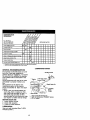
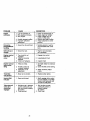
SCHEDULE
MAINTENANCE
_A
_/_/
AS YOU COMPLETE
REGULAR SERVICE
Check
Engine
ERVICE
Oil Level
_
DATES
It_
Change Engine Oil
1_!,2
Oil Pivot Points
It_
inspect Spark Arrester / Muffler
inspect
Air Screen
If
Clean or Replace Air Cleaner Cartridge
f_2
Clean Engine Cylinder Fins
t/
Replace Spark Plug
RH Gear
Case
Grease
II/
FRtlng (1oz.)
I1_
1 - Ch4mge more often when operating under a heavy _ad or in highambient temperatures
2.
Service
more
offer1 Whell
opera,:lr_j
hi _rly
or dusty coP.dttlo:ls,
LUBRICATION CHART
GENERAL RECOMMENDATIONS
The warranty on this tiller does not cover
items that have been subjected to
operator abuse or negligence, To receive
full value from the warranty, the operator
must maintain tiller as instructed in this
manual.
Some adjustments will need to be made
periodically to properly maintain your
tiller.
All adjustments in the Service and
Adjustments section of this manual
should be checked at least once each
season.
• Once a year you should replace the
spark plug, clean or replace air filter,
and check tines and belts for wear. A
new spark plug and clean air filter
assure proper air-fuel mixture and help
your engine run better and last longer.
BEFORE EACH USE
"Throttle Control
** Engine
***RH Gear Case_
Grease Fitting
* SAE 30 OR 5W-30 Motor Oil
** Refer to Maintenance "ENGINE" Section
*** EP #1 Grease
1. Check engine oil level,
2, Check tine operation.
3. Check for loose fasteners.
LUBRICATION
Keep unit well lubricated (See "LUBRICATION CHART").
13
_kCAUTlON:Disconnect spark plug wire
before performingany maintenance
(exceptcarburetoradjustment)to prevent
accidental startingof engine.
Preventfires! Keep the enginefree of
grass,leaves, spilledoil, or fuel. Remove
fuel from tank beforetippingunitfor
maintenance. Clean muffler area of ell
grass,dirt, and debris.
Do not touch hot muffleror cylinderfins
as contactmay cause bums.
ENGINE
LUBRICATION
Use onlyhigh qualitydetergentoil rated
with API serviceclassificationSF-SJ.
Select the oil'sSAE viscositygrade
accordingto your expected temperature.
NOTE: Althoughmulti-viscosity
oils (5W30, 10W-30, etc.) improvestartingin cold
weather,these multi-viscosity oils will
resultin increasedoil consumptionwhen
used above 32°F (0°C). Check your
engine oil level more frequently to avoid
possibleengine damage from running
low on oil.
Change the oil after every 50 hoursof
operationor at leastonce a year if the
tiller is not used for 50 hoursin one year.
Check the crankcase oil level before
startingthe engine and after each five (5)
hoursof continuoususe. Add SAE 30
motoroil or equivalent. Tighten oilfiller
plug securelyeach time you check the oil
level.
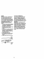
TO CHANGE ENGINE OIL
Determine temperature range expected
before oil change. All oil must meet API
service classification SF-SJ.
• Be sure tiller is on level surface.
• Oil will drain more freely when warm.
• Use a funnel to prevent oil spill on tiller,
and catch oil in a suitable container.
1. Remove drain plug.
2. Tip tiller fonNard to drain oil.
3. After oil has drained completely,
replace oil drain plug and tighten
securely.
4. Remove oil filler plug. Be careful not
to allow dirt to enter the engine,
5. Refill engine with oil.. See ."CHECK'
ENGINE OIL LEVEL in the Operation
section of this manual.
Oil drain
Oil Fill Plug
AIR FILTER
Your engine will not run properly using a
dirty air filter. Clean the foam pre-cleaner
after every 50 hours of operation or every
season. Service paper cartridge every
100 hours of operation or every season,
whichever occurs first.
Service air cleaner more often under
dusty conditions.
1. Remove knob and cover. Lift air
cleaner assembly oft stud.
TO SERVICE PRE-CLEANER
2. Remove foam pre-cleaner from air
filter.
3. Wash it in liquid detergent and water.
4. Squeeze it dry in a clean cloth.
NOTE: If very dirty or damaged, replace
pre-cleaner.
5. Reinstall pre-cleaner onto air filter.
6. Reinstall cover and secure with knob.
TO SERVICE CARTRIDGE
1. Carefully remove cartridge to prevent
debris from entering carburetor.
Clean base carefully to prevent debris
from entering carburetor.
2. Remove foam pre-cleaner from air
filter.
3. Clean cartridge by tapping gently on
flat surface. If very dirty or damaged,
replace cartridge.
4. Reinstall pre-cleaner onto air filter.
5. Reinstall cover and secure with knob.
IMPORTANT: Petroleum solvents, such
as kerosene, are not to be used to clean
the cartridge. They may cause deterioration of the cartridge. Do not oil cartridge.
Do not use pressurized air to clean or dry
cartridge.
14
Stud
COOLING SYSTEM
Your engine is air cooled. For proper
engine performance and long life keep
your engine clean.
• Clean air screen frequently using a
stiff-bristled brush.
• Remove blower housing and clean as
necessary.
• Keep cylinder fins free of dirt and chaff.
Muffler
MUFFLER
Do not operate tiller without muffler. Do not
tamper with exhaust system. Damaged
mufflers or spark arrestera could create a
fire hazard. Inspect periodically and
replace if necessary. If your engine is
equipped with a spark arrester screen
assembly, remove every 50 hours for
cleaning and inspection. Replace if
damaged.
SPARK PLUG
Replace spark plugs at the beginning of
each tilling season or after every 50 hours
of use, whichever comes first. Spark plug
type and gap setting is shown in "PRODUCT SPECIFICATIONS" on page 4 of this
manual.
TRANSMISSION
Once a season, lubricate the right hand
gear case grease fitting with 1 oz. of EP #I
grease.
CLEANING
Do not clean your tiller when the engine
and transmission are hot. We do not
recommend using pressurized water
(garden hose, etc.) to clean your unit
unless the gasket area around the
transmission and the engine muffler, air
filter and carburetor are covered to keep
water out. Water in engine will shorten the
useful life of your tiller.
• Clean engine, wheels, finish, etc. of all
foreign matter.
• Keep finished surfaces and wheels free
of all gasoline, oil, etc.
• Protect painted surfaces with automotive type wax.
_CAUTION: Disconnect spark plug wire
from spark plug and place wire where it
cannotcome intocontactwith plug.
TILLER
Handle (High) Position
";i;_";'/Handle
TO ADJUST HANDLE HEIGHT
Select handle height best suited for your
tilling conditions. Handle height will be
different when tiller digs into soil.
1. First loosen handle lock lever.
2. Handle can be positioned at different
settings between "HIGH" and "LOW"
positions.
3. Retighten handle lock lever securely
after adjusting.
Handle (Low) Position
15
Lock Lever
TIRECARE
_CAUTION: When mountingtires,unless
beads are seated, ovednflationcan
cause an explosion.
• Maintain20 poundsof tire pressure. If
tire pressuresare not equal, tiller will
pull to one side.
• Keep tires free of gasolineor oil which
can damage rubber.
TO REMOVE WHEEL
1. Place blocksunder transmissionto
keep tiller from tipping.
2. Remove hairpinclip and clevis pin
from wheel
3. Remove wheel and tire.
4. Repair tire end resssemble.
TO REMOVE BELT GUARD
NOTE: For ease of removal, remove
hairpinclip and clevispin from leftwheel.
Pullwheel out from tiller about 1 inch.
1. Remove two (2) screwsfrom side of
belt guard.
2. Remove hex nut and washer from
bottomof belt guard (locatedbehind
wheel).
3. Pullbelt guard out and away from unit.
4. Replace belt guard by reversing
above procedure.
_F/Hex
Nut
_S
_:she
_:;uard '_._
v
r
Lo.to,
Behind
\\ Tire
Hairpin Clip and Clevis Pin
TO REPLACE GROUND DRIVE BELT
1. Remove belt guard as describedin
"TO REMOVE BELT GUARD".
2. Remove old belt by slippingoff engine
pulleyfirst then remove from transmlss_onpulley.
3. Place new belt in grooveof transmission pulley and into engine pulley.
BELT MUST BE IN GROOVE ON TOP
OF IDLER PULLEY. NOTE POSITION
OF BELTTO GUIDES.
4. Check belt adjustmentas dascdbed
below.
5. Replace belt guard.
6. Repositionwheel and replace clevis
pin and hairpinclip.
GROUND DRIVE BELT ADJUSTMENT
For properbelt tension,the extension
springshouldhave about 5/8 inchstretch
when drivecontrol bar is in "ENGAGED"
position.This tensioncan be attainedas
follows:
t. Loosen cable clip screwsecudngthe
drive controlcable.
2. Slide cable forward for lesstension
and rearward for more tensionuntil
about
5/8 inchstretch is obtainedwhilethe
ddve controlbar is engaged.
3. Tighten cable clip screw securely.
Screw
Idler Pulley
_ore Tension
TransmissionPulley
16
• To maintain the superb tilling performance of this machine the tines should
be checked for sharpness, wear, and
bending, particularly the tines which
are next to the transmission If the gap
between the tines exceeds 3-1/2
inches they should be replaced or
straightened as necessary.
• New tines should be assembled.
Sharpened tine edges will rotate
rearward from above.
TINE REPLACEMENT
_.CAUTION: Tines are sharp. Wear
gloves or other protection when handling
tines.
A badly worn tine causes your tiller to
work harder and dig more shallow. Most
important, worn tines cannot chop and
shred organic matter as effectively nor
bury it as deeply as good tines. A fine this
worn needs to be replaced.
Worn Tine
New Tine
ITrani_\Transmission
T_
o
3.1/_2_
f_
MAX
Counter Tine
Rotation
Shear Pin
Shear Pin_ Sharp Edge
_
__
Sharp Edge
|
("
_;:_
Sharp
\ __'_
\
Sharp
HairpinClip
Edge
17
Tine
ENGINE
Maintenance, repair, or replacement of
the emission control devices and systems, which are being done at the
customers expense, may be performed
by any non-road engine repair establishment or individual. Warranty repairs must
be performed by an authorized engine
manufacturer's service outlet.
TO ADJUST THROTTLE CONTROL
CABLE
1. The throttle control has been preset at
the factory and adjustment should not
be necessary, if adjustment is
necessary, proceed as follows:
2. With engine not running, move remote
throttle control lever to "FAST"
position.
3. If throttle lever on engine touches high
speed stop, no further adjustment is
necessary. If throttle lever does not
touch high speed stop, continue with
adjustment procedure.
4. Loosen cable clamp screw.
5. Move throttle lever up until it touches
high speed stop, and hold in this
position.
6. Tighten cable clamp screw securely.
TO ADJUST CARBURETOR
The carburetor has been preset at the
factory and adjustment should not be
necessary. However, engine performance can be affected by differences in
fuel, temperature, altitude or load. If the
carburetor does need adjustment, contact
your nearest authorized service center/
department
IMPORTANT: Never tamper with the
engine governor, which is factory set for
proper engine speed. Overspeeding the
engine above the factory high speed
setting can be dangerous. If you think tt
engine-governed high speed needs
adjusting, contact your nearest authorized service center/department, which
has the proper equipment and experience to make any necessary adjustments.
./ Clamp
/Screw
/ Casing
and Wire
_Govemor
Control
Lever
18
Immediately prepare your tiller for storage
at the end of the season or if the unit will
not be used for 30 days or more.
_,CAUTION:
Never store the tiller with
gasoline in the tank inside a building
where fumes may reach an open flame or
spark. Allow the engine to cool before
stodng in any enclosure.
TILLER
1. Clean entire tiller (See "CLEANING" in
the Maintenance section of this
manual).
2. Inspect and replace belts, if necessary
(See belt replacement instructions in
the Service and Adiustments section
of this manual).
3. Lubricate as shown in the Maintenance section of this manual.
4. Be sure that all nuts, bolts and screws
are securely fastened. Inspect moving
parts for damage, breakage and wear.
Replace if necessary.
5. Touch up all rusted or chipped paint
surfaces; sand lightly before painting.
ENGINE
FUEL SYSTEM
IMPORTANT: It is important to prevent
gum deposits from forming in essential
fuel system parts such as the carburetor,
fuel filter, fuel hose, or tank during
storage, also, expedence indicates that
alcohol blended fuels (catted gasohot or
using ethanol or methanol) can attract
moisture which leads to separation and
formation of acids during storage. Acidic
gas can damage the fuel system of an
engine while in storage.
1. Drain the fuel tank.
2. Start the engine and let it run until the
fuel lines and carburetor are empty.
• Never use engine or carburetor cleaner
products in the fuel tank or permanent
damage may occur.
• Use fresh fuel next season.
NOTE: Fuel stabilizer is an acceptable
alternative in minimizing the formation of
fuel gum deposits dudng storage. Add
stabilizer to gasoline in fuel tank or
storage container. Always follow the mix
ratio found on stabilizer container. Run
engine at least 10 minutes after adding
stabilizer to allow the stabilizer to reach
the carburetor, Do not drain the gas tank
and carburetor if using fuel stabilizer.
ENGINE OIL
Drain oil (with engine warm) and replace
with clean oil. (See "ENGINE" in the
Maintenance section of this manual).
CYLINDER
I. Remove spark plug.
2. Pour I ounce (29 ml) of oil through
spark plug hole into cylinder.
3. Pull starter handle slowly several
times to distribute oil.
4. Replace with new spark plug.
OTHER
• Do not store gasoline from one season
to another.
• Replace your gasoline can if your can
starts to rust. Rust and/or dirt in your
gasoline will cause problems.
• If possible, store your unit indoors and
cover it to give protection from dust and
dirt.
• Cover your unit with a suitable protective cover that does not retain moisture.
Do not use plastic. Plastic cannot
breathe which allows condensation to
form and will cause your unit to rust.
IMPORTANT: Never cover tiller while
engine and exhaust areas are still warm.
19
PROBLEM
Willnotstart
CAUSE
CORREC_ON
1. Out of fuel.
2. Engine not "CHOKED"
properly.
3. Engine flooded.
4. Dirty air cleaner.
5. Water in fuel.
6. Clogged fuel tank.
7. Loose spark plug wire.
8. Bad spark plug or
improper gap.
9. Carburetor out of adjustment.
t0.Oil soaked air filter,
Hard to start
1. Throttlecontrolnot set
properly.
2. Dirtyair cleaner.
3. Bad spark plug or
improper gap.
4. Stale or dirty fuel.
5. Loose spark plug wire.
6. Carburetor out of adjustment.
Loss of power
1. Engine is ovedoaded.
2. Dirtyair cleaner.
3. Low oil level/dirty oil,
4. Faultyspark plug.
5. Oil in fuel.
6. Stale or dirty fuel.
7. Water in fuel,
8. Clogged fuel tank.
9. Spark plug wire loose.
t0.Dirty engine air screen.
1t .Dirty/clogged muffler.
12.Carburetor out of adjutsment.
13.Poor compression.
20
t. Fill fueltank.
2. See "TO START ENGINE" in
the Operationsection.
3. Wait several minutesbefore
attemptingto start.
4. Clean or replace aimleaner
cartridge.
5. Drain fuel tank and carburetor,and refilltankwith fresh
gasoline.
6. Remove fuel tank and clean.
7. Make sure spark plug wire is
seated properlyon plug.
8. Replace spark plug or adjust
gap,
9. Make necessary adjust
ments.
lO,Replace air filter.
1. Place throttlecontrolin
"FAST" position.
2. Clean or replace air cleaner
cartridge.
3. Replace spark plug or adjust
gap.
4. Drain fuel tankand refill with
fresh gasoline.
5, Make sure spark plug wire is
seated properlyon plug.
6. Make necessary adjust
ments.
1. Set depth stake and wheels
for shallower tilling.
2. Clean or replace aircleaner
cartridge.
3. Check oil level/change oil.
4. Clean and regap or change
spark plug.
5. Drain and clean fuel tank
and refill, and clean carbure
tor.
6. Drain fuel tank and refill
with fresh gasoline.
7. Drain fuel tank and carburetor, and refill tank with fresh
gasoline.
8. Remove fuel tank and clean.
9. Connect and tighten spark
plug wire.
10.Clean engine air screen.
11 .Clean/replace muffler.
12.Make necessary adjustments.
13.Contact a Sears or other
qualified service center.
PROBLEM
Engine
overheats
CAUSE
CORRECTION
1. Low oil level/dirty oil.
2. Dirty engine air screen.
3. Dirty engine.
4. Partially plugged muffler.
5. Improper carburetor
adjustment.
1. Check oil level/change oil.
2. Clean engine air screen.
3. Clean cylinder fins, air
screen, muffler area.
4. Remove and clean muffler.
5. Adjust carburetor to richer
position.
Excessive
bounce/difficult
handling
1. Ground too dry and hard.
1. Moisten ground or wait for
more favorable soil conditions.
Soil balls up or
clumps
!. Ground too wet.
1. Wait for more favorable
soil conditions.
Engine rune but
tiller won't
move
Tine control is not
engaged.
2. V-belt not correctly
adjusted.
3. V-belt is off pulley(s).
1. Engage tine control.
1. Tilling too deep.
1. Set depth stake for shallower
tilling.
2. Check throttle control setting.
Engine runs but
labors when
tilling
1.
2. Throttle controlnot
2. Inspect/adjust V-belt.
3. Inspect V-belt.
properlyadjusted.
3. Carburetorout of
3. Make necessary adjust
ments.
adjustment.
Tines Skip
over ground
1. Shear pin (s) broken.
1. Replace shear pin(s).
Hard to Shift
into gear
!. Gears not timmed.
1. Briefly engage drive control
bar and release or reck tiller
forward and backward until
are able to shift gears.
Tiller shuts off
when drive
control bar
engaged
1. Shift lever set in between
counter rotating till position and forward rotating
till position.
2. Tines jammed.
21
1. Shift to either counter
rotating till position or
forward rotating
till position.
2,
Clear tines.
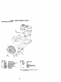
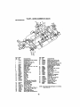
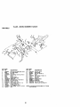
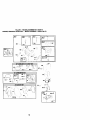
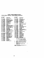
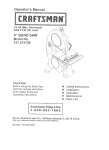
TILLER-- MODELNUMBER
917.293470
HANDLES
7
8
9
4
2
15
31
KEY
NO.
PART
NO.
DESCRIPTION
1
2
3
4
5
6
7
8
9
10
11
12
13
14
15
16
17
175250
141406
110673X
127254X
6712J
137119
110641X
71191008
72010520
110646X
STD624003
81328
110741X
109313X
11070_X
STD533710
109229X
Throttle, Control
Gdp,Haodle
Grommet, Handle
Bar, Ddve Control Assembly
Cap, Vinyl
Panel,Control
Bushing, Sl_lt
Screw, Pan Head #10-24
Bolt, 5/16-18 x 2-1/2
Handle,Grip
Clip, Hairpin
Bolt, Shoulder
Handle, Shift
Grommet, Rubber
Rod, Shift
Bolt, Carriage 3/8o16 x 1 Gr. 5
Lcck, Handle
KEY
NO,
PART
NO.
18
19
20
21
22
23
STD541437
19131611
109228X
15_58
165197
86777
24
25
26
27
29
31
9484R
73970500
110675X
73900400
STD541462
1506_6
NOTE:
42
\\
DESCRIPTION
Nut, Crownlock 3/8-16
Washer 13/32xl
xll
Ga.
Lever, Lock, Hanole
Haodk_, Assemble
Clip, Plastic, Cable
Screw, Hex, Washer Hd, Sloited
#10-24 x 1/2
Cap
Locknut, Hex, Flange
Clutch,Cable
Nut, Hex Flange 1/4-20
Nut, Keps #10-24
Bolt, PIvot
All component dimensions given in US.
inches. 1 inch = 25.4 mm
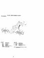
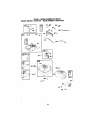
TILLER-- MODELNUMBER
917.293470
MAINFRAME,
LEFTSIDE
\
3O
2e
KEY
NO.
PART
NO,
1
2
3
4
5
6
7
8
9
STD541431
STD551137
STD541037
170127
154734
110111X
ST[To32505
8700J
86777
10
11
12
13
14
15
16
19
21
22
23
9484R
ST1_o51125
STD541(_5
2323_506
110652X
STD551(_31
145102
12000028
156117
7477(_o08
1(_190X
150750
795R
126875X
' 24
3
DESCRIPTION
Nut,Kept;FlangeS/16-18
Washer, LoCk 3/8
Nut, Hex 3/8o16
Sl_eld, Inner Belt Guard
Screw Shift Lever
Lever, ShJlt
B01t,Carrlage 1/4-20xl/2Gr.
5
Plate, Shift Indicator
Screw, Hex, WasherHead,
Slotted #10-24 x 1/2
Clip
Washer, Lock 1/4
Nut, Hex 1/4-20
Screw, Bet, 5/16-18 x 3/8
Spacer, Spilt .327 x .42 x 2.09
Washe( 11/32xll/16x16Ga.
Sheave, Transmission
Ring, Retainer
Spacer, Spilt .327 x .42 x 1.220
Bolt, Fin Hex 5/16-24 x 1/2
"llre
Rm
Tire Valve
Rivet, Drilled
KEY
NO.
PART
NO,
DESCRIPTION
25
26
27
28
29
30
31
32
33
34
35
36
37
38
39
40
43
44
STC_24003
165501X558
132801
104679X
12000032
15S229
1(_194X
1(_141X
STD523710
1(_173X
74760624
1_331X
13_612
7476C544
140062
170488
69180
73800500
Clip, Hair_n
Guard, Belt
Belt, V
Pufley, Idler
Ring, KIIp
Bracket, Idler
Bolt, Hex 5/16-16x10
Shaft, Idler Arm
Bolt,Hex 3/6-16xl
Counterweight, L.H.
Bolt, Hex 5/16-18 x 1-1/2
Bracket, Reinforcement, L.H.
Sheave, Engine
Boft, Fin Hex 5/16-18 x 2-3/4
Cap, Plunger
ScrewHexWsh.
Hd#10-32x9/16
Nut Lock #10,24
Nut, LOCk Hex w/ins 5/16-18
NOTE: All component dimensions given In U.S.
inches. 1 inch = 25.4 mm
43
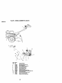
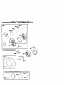
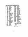
TILLER-MAINFRAME, RIGHT SIDE
MODEL NUMBER 917.293470
18
Y
12
5
i
10
11
10
KEY
NO,
PART
NO.
DESCRIPTION
2
5
7
8
9
10
11
12
73970500
10_J32X
102173X
STD551137
STD5410_7
7476_24
STD624003
126875X
Locknut, Hex, Flange 5/16-18
Bracket, Reinforcement
Counter Weight, R,H,
Washer, Lock 3/8
Nut, Hex 3/8-16
Bolt, Hex 5/16-18 x 1-1/2
CHp,Hairpln
Rivet, Ddlled
KEY
NO,
PART
NO,
13
15
1021gOX
150750
7O_R
......
16
7192J
NOTE:
44
DESCRIPTION
Tlre
Fin
Tire Valve
Engine, (See Breakdown)
Craftsman Model NO, 1104020180-E1
TieCable
All component dimensions given in U.S.Inches.
1 Inch = 25.4 mm
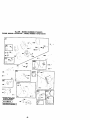
TILLER-- MODELNUMBER
917.293470
24
11
KEY
NO.
PART
NO,
1
170337
2
165729
3
4
5
6
7
8
9
10
11
12
13
14
15
16
18
19
20
161963
5020J
1370H
137335
145101
4895H
154467
7392M
I00371K
I06160X
142145
8353J
12000039
154466
4358J
1200(_40
10_2114X
21
22
23
24
25
27
28
: 29
30
31
1G2115X
6803J
10_2t11X
STD551t43
STD541143
143009
106390X
10_134X
150737
143008
DESCRIPTION
Transmission Assembly (Includes
Key Nce. 2-52)
Gearcase, L,H. w/Bearing
(Includes Key No. 4)
Gasket, Gearcase
Bearing, Needle
Washer, Thrust 5/8 x 1.10 x 1/32
Pinion, Input
Shaft, Input
Bearing, Needle
Washer, Seal
B_I, Steel
Spdng, Shift, Fork
O-l_ng
Arm, Shift
Fork, Shift
Ring, Kllp
Shaft, Shift
Washer
Rlng, Klip
Gear, Assembly, Reverse Idler
(Includes Key Nce, 21 and 22)
Gear, ReverSe Idler
Beadng, Needle
Shaft, Reverse Idler
Washer, LoCk 7/16
Nut, Hex 7/16-20
Beadng, Shaft, Ground Ddve L.H,
Spacer 0.765 x 1.125 x 1.23
Chain #35-50 Pitch
Ground Shaft Assembly
Seadng, Shaft, Ground Ddve R.H.
KEY
NO,
PART
NO.
32
33
34
35
36
106388X
1(_121X
1G2112X
1G2101X
154355
37
38
39
40
41
42
43
44
48
4422J
154356
1(To345X
105346X
8358J
4220R
I06146X
155236
170338
49
50
51
52
53
58
60
- -
NOTE:
45
132688
106147X
17720408
STD6410_1
165140
17720412
6855M
6066J
DESCRIPTION
Spacer 0.70 x 1.00 x 1.150
Sprocket and Gear Assembly
Shaft, Reduction (2nd)
Screw, WIdz, Lod( 5/1 6.18 x 3-1/2
Sprocket Assemb;y w/Bearing
(Includes Key Nos. 37 and 38)
Beaftng, Needle
Sprocket, line
Gear, Cluster, Red 1st & 2nd
Gear, Reverse
Shaft, Redoctlon (1st)
Washer, Thrust
Spacer 1.01 x 1.75 x 0.760
Seal Asm. O11
Geemase, R.H, w/Beadng
(Includes Key No, 8)
Shaft, Tine
Chain, ROller #50-50Pitch
Screw 1/420 x 1/2
Nut, Hex 5/16-18
Seadng Kit, line Shaft
Screw 1/4-20 x 3/4
Fitting Grease
Grease, Plastilube #1
AIIcomponantdlmenaionsgiveninU.S.inches.
1 Inch = 25,4 mm
TILLER - - MODEL NUMBER 917.293470
TINE SHIELD
I
24
KEY
NO.
PART
NO.
DESCRIPTION
1
3
4
5
5
7
8
9
10
11
12
13
14
16
18
19
739(XTo(X)
8393J
12000036
STD533107
8394J
8392J
1(Y3230X
102152X558
72140508
STD541031
STD551131
S_112
124343
739OO4OO
STD532512
102701X
Nut, Lock Hex Flange 5/16-18 Unc
Pin, Stake, Depth
Ring, Klip
Bolt, Carriage 5/16-18 x 3/4 Gr 5
Spdng
Bracket, Latch
Spring, Depth Stake
Shtald, Tthe
Bolt, Rehd Sqnk 5/16-18 Unc x 1
Nut, Hex 5/16-15
Washer, Lock 5/16
Bolt, Cardage 5/16-18 x 1-1/4
Bracket, Shield Tine
Nut, Flange lock 1/4-20
Bolt, Carriage 1/4-20 x 1-1/4 Gr. 5
Grip
46
KEY
NO.
PART
NO.
DESCRIPTION
20
21
22
23
24
25
26
27
28
29
32
33
ST[To41G37
10_156X
74930632
4440J
s'r[_-_32505
6712J
109227X
102686X558
12(To88X
104085X558
s'rD,541(_25
S_To51125
Nut, Hex 3/8-16
Stake, Depth
Bolt, Hex 3/8-16 x 2
Hinge
Bolt, Cardage 1/4-20 x 1/2
Cap, Vinyl
Pad, Idler
ShFeld, Leveling
Pin, Hinge
Shield, Side
Nut, Fin, Hex 1/4-20
Washer Lock Hvy Helical 1/4
NOTE:
All component dimensions given in U.S. inches
1 inch = 25.4 mm
TILLER-- MODELNUMBER917.293470
TINEASSEMBLY
2
4
4
(EY
PART
IO,
NO.
DESCRIPTION
4459J
132673
6554J
3146R
132721
73610600
STD551137
Tlne, Outer, L.H.
Pin, Shear
Tine, Inner, LH.
Clip, Hairpin
AsSembly, Hub and Plate, L.H.
Nut, Hex 3/8-24
Washer, Lock 3/8
KEY
NO.
PART
NO.
DESCRIPTION
8
9
10
11
74610616
4460J
132722
6555J
Bolt, Hex 3/8-24 x 1
Tine, Outer, R.H.
Assembly, Hub and Plate, R.H.
Tlne, Inner, R.H.
NOTE:
47
All component dimensions given In U.S. inches.
1 inch = 25.4 mm
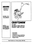
TILLER - - MODEL NUMBER 917.293470
DECALS
-
7
KEY
NO,
PART
NO.
DESCRIPTION
1
2
4
5
6
7
8
9
10
11
12
13
- -
176738
176736
137538
120431X
102180X
166138
167156
120075X
187984
171078
162215
163094
176753
Decal, Service CNTRL PNL
Decal, Belt Guard
Decal, Caution, Drive Contrdi
Decal, Hand Ptacement
Decal, Shift Indicator
Decal, Operation Intak
Decal, B & S Intak
Decal, Warning, Rotating Tines
Decal, Tlne, Shield, Counter Rotating Tines
Decal, Rewind Intek
Decal, Tlne, Shield, Warning Dora
Decal, Tine Depth Stake
Manual. Owner's (Eng/Span)
48
TILLER-- MODEL NUMBER 917.293470
ENGINE, BRIGGS & STRATTON - -.MODEL NUMBER 110402-0180-E1
51
61
1022
"
914A
_ +
415 _
_.
12
r_
718 -
1113 :',
16
<*
478
22+•+
i__ , -_%_
_
21 _"
2O
_" REQUIRES EPECIALTOOLS
TO INSTALL SEE REPAIR
INSTRUCTION MANUAL,
1016 LABEL
KIT
1058 OWNER'S
32
742
746
]
MANUAL
_
_._
27 +
f
49
,-.
+ ,ii +' i: +,
"-,,
46
Pi30;
TILLER - - MODEL NUMBER 917.293470
ENGINE, BRIGGS & STRA'rTON - - MODEL NUMBER 110402-0180-E1
276 i_h
TJ
276 _ i_
968
°
{:
P
I
[
,
I
_67
358 GASKET
: L
I
i
SET
875
423A
I Ir+_
I _ +_
|
5O
!
_+ !
++I
"+ °1
TILLER - - MODEL NUMBER 917.293470
ENGINE, BRIGGS & STRATFON - - MODEL NUMBER 110402-0180-E1
209A
r__
1054
427
334_
615 _
19o
190A <_
N
736 t_
883
51
TILLER-- MODELNUMBER
917.293470
ENGINE,
BRIGGS
& STRATTON
- - MODEL
NUMBER
110402-0180-E1
597
450
e09
450
I
/
7"
L/
5
592
65 _
I 1036 EMISSIONS LABEL
I
363_
305
1033 VALVE OVERHAUL KIT
868
1022
_i
01
52
TILLER - - MODEL NUMBER 917.293470
ENGINE, BRIGGS & STRA'I-rON - - MODEL NUMBER 110402-0180-E1
KEY
NO.
PART
NO.
1
2
3
5
7
11
ltA
12
13
15
16
18
20
21
22
23
24
25
693811
Cylinder Assembly
399269
Bushing/Seal Kit
299819
• Oil Seal
693643
Cylinder Head
273489 =+ Cylinder Head Gasket
692600
Breather Tube
693647
Breather Tube
692549
° Crankcase Gasket
691137
Screw (Cylinder Head)
94916
Oil Drain Plug
693797
Crankshaft
694466
Crankcase Cover
692550
° Oil Seal
281658
Oil Fill Cap
692551
Screw (Crankcase Cover)
692987
Flywheel
222698
Flywheel Key
690021
Piston Assembly (Standard)
694167
Piston Assembly (.010" O/S)
694168
Piston Assembly (.020" Q/S)
694169
Piston Assembly (.030" O/S)
499631
Ring Set (Standard)
692785
Ring Set (.010" O/S)
692786
Ring Set (.020" O/S)
692787
Ring Set (.030" O/S)
263190
Piston Pin Lock
499423
Piston Pin
499424
Connecting Rod
692562
Connecting Rod Dipper
94699
Screw (Connecting Rod)
499642
Exhaust Valve
499641
Intake Valve
691304
Valve Spring (Intake)
691304
Valve Spring (Exhaust)
93312
Valve Retainer
262679
Valve Tappet
Camshaft
693404
692555o+g¢lntake Gasket (2 Required)
891422
Rewind Starter Housing
498144
Pulley/Spring Assembly
498144
Pulley/S_ring Assembly
693449
StarterHope
391101
Starter Rope Gdp
94904
Screw (Rewind Starter)
94098
Screw (Throttle Valve
690024
Throttle Shaft
398185
Idle Spsed Kit
691242
a Float Hinge Pin
692567
Choke Valve
693628
Choke Shaft
493763
Main Jet
690032
Carburetor Kit
693749
_ Carburetor Spacer
26
27
28
29
30
32
33
34
35
36
40
45
46
51
55
56
57
58
60
65
95
97
98
104
108
109
117
121
122
DESCRIPTION
KEY
NO.
PART
NO.
DESCRIPTION
125
127
130
133
134
137
146
155
163
186
187
694112
Carburetor
223472
_ Welch Plug
691181
Throttle Valve
398187
Carburetor Float
398188
_ Needle Valve
693981 _1:1:Float Bowl Gasket
94388
Timilg Ksy
692556
Cylinde Her ed Plate
693458,+ _:l:AIr Cleaner Gasket
493496
Hose Connector
492790
Fuel Line (Cut to Required
Length
187A 692601
Fuel Line (Molded)
188 94644
Screw Control Bracket)
189 691295
Rocker Arm Ba
190 692127
Screw (Fuel Tank)
190A 94644
Screw (Fuel Tank)
209
693710
Governor Spring
209A 261306
Govemor Spring
219
693578
Governor Gear
220
221551
Washer (Governor Gear)
222
694253
Control Bracket
227 692573
Governor Lever
238
691300
Valve Cap
265
221535
Casing Clamp
267
692577
Screw (Casing Clamp)
276
271716 (_:_ Sealing Washer
281
694252
Control Panel
300
693593
Exhaust Muffler
304 693621
Housing-Slower
305 692608
Screw (Blower HOUsing)
306 693610
Cylinder Shield
307
690345
Screw (Cylinder Shield)
332
94877
Nut (Flywheel)
333
692605
Armature-Magneto
334
94731
Screw (Magneto Armature)
337
491055
Sparkplug
356
398808
Stop Wire
358
690031
Gasket Set
363
19069
Flywheel Puller
365
692568
Screw (Carburetor)
RPM Settings:Low Speed: 1900-2100
High Speed: 3000-3200
-g
:1:
+
Included in Gasket Set, Bef Humber 358.
Included in Carburetor Kit, Ref Number
121.
Included in Carburetor Gasket Set, Ref
Number 977,
Included in Value Overhaul Kit, Ref
Number 1033.
NOTE: All component dimensions given in U.S.
inches 1 inch = 25.4 mm
53
TILLER - - MODEL NUMBER 917.293470
ENGINE, BRIGGS & STRATTON - - MODEL NUMBER 110402-0180-E1
KEY
NO.
PART
NO.
383
415
423
423A
427
445
455
456
459
467
478
504
505
552
562
592
597
601
608
613
615
616
619
621
632
19374
693463
690349
94929
692575
690610
692591
281503
281505
493903
693709
495659
231082
692346
94852
94908
94943
95162
497830
94706
692576
692547
691108
396847
693408
633
635
663
676
677
689
692
708
717
718
736
741
742
746
798
693867 _.
805529
694593
393757
94896
263073
690572
691321
693462
230192
693560
263157
692564
692566
692559
DESCRIPTION
Spark Plug Wrench
Oil Fill Plug
Screw Air Cleaner Base)
Screw Ar Cleaner Base)
Nut (Control Bracket)
AiC Cartridge Filter
Flywheel Cup
Pawl FdcUco Plate
Ratchet Pawl
Air Cleaner Knob
Panel
Washer Set
Nut (Governor Control Lever)
Governor Crank Bushing
Bolt (Governor Control Lever)
Nut (Rewind Starter)
Screw (Pawf Fdollon Plate)
Hose Clamp
Rewind Starter
Screw (Muffler)
Governor Shaft Retainer
Governor Crank
Screw (Cytinder Head Plate)
Stop Switch
Spring/Link(Mechanical
Governor)
Washer (Choke Shaft)
Spark Plug Boot
Screw Control Panel)
Muffet Deflector
Screw (Muffler Deflector)
Friction Spdng
Detent Spring (Choke)
Washer (Throttle Shaft)
Air Cleaner Bracket
Locating Pin
Nut Ctip
TimingGear
Ring-Retaining
Gear-tdler
Screw (ROcker Arm)
KEY
NO.
pART
NO.
832
836
836A
843
851
868
875
883
914
693583
Muffler Guard
94896
Screw (Muffler Guard)
693624
Screw (Mounting)
694061
Lever Sleeve
493880
Sparkplug Terminal
498592 ,+ Valve Seal
693459
Air Cleaner Base
272309
Exhaust Gasket
94786
Screw (Rocker Cover 7/16"
Long)
692557
Screw (Rocker Cover 3/8"
Long)
493988
Fuel Tank Cap
692586
Shutoff Valve
693598
Screw Air Cleaner Bracket
273356
Pre.Ceaner F tsr
693460
Air Cleaner Cover
692587
Fuel Tank
493640
Float Bowl
690033
Carburetor Gasket Set
691892 -+ Cy,nder Head Plate Gasket
692592
Fan-Flywheel
690035
Label kit
693790 .+ Rocker Cover Gasket
499924
Rocker Cover
693517
Push Rod
691230
RockerArm
690034
Valve Overhaul Kit
691343
Push Rod Guide
695041
Emissions Label
692590
Screw (Flywheel)
692558
Nut Rocker Arm)
280275
Cabe Te
273700
Owner's Manual
692577
Screw (Panel)
121432-0036-E2Replacemant Engine
914A
957
958
961
967
968
972
975
977
993
1005
1019
1022
1023
1026
1029
1033
1034
1036
1044
1050
1054
1058
1113
----
DESCRIPTION
RPM Settings:Low Speed: 1900-2100
High Speed: 3000-3200
•
O
€
+
Included In Gasket Set, Ref Number 358.
Included in Carburetor Kit, Ref Number
121.
Included in Carburetor Gasket Set, Ref
Number 977.
included in Value Overhaul Kit, Ref
Number 1033.
NOTE: All component dimensions given In U.S,
inches 1 inch = 25.4 mm
54
55
Get it fixed, at your home or ours!
For repair of major brand appliances In your own home...
no matter who made it, no matter who sold it!
1-800-4-MY-HOME
s"
Anytime,day or night
(1-800-469-4663)
www.sesrs.com
To bring in products such as vacuums,
lawn equipment and electronics for repair, call for
the location of your nearest Sears Parts & Repair Center.
1-800-488-1222
A_,, day,_night
www.sears.com
For the replacement pads, accessories and owner's manuals
that you need to do-it-yourself, call Seers PartsDirsctSM!
1-800-366-PART 6am- 1_p.m.
CST,
(1-800-366-7278)
7 days a week
www.sears.com/partsdlrect
To purchase or inquire about a Sears Service Agreement:
1-800-827-6655
7 a.m.- 5 p.rn.CST,Mon.- Sat.
Para pedir servicto_e reparaclbna domictllo,
y para orden_ plezas con entrega a domlcJlio:
1-888-SU-HOGAR
_
(1-888-784-6427)
Au Canada pourservice en fran_ats:
1-877-LE-FOYE
R =_
(1-877.533-6937)
SEARS 1
HomeCentral ®
® RegisteredTrademark / T. Trademark of Sears, Roebuck andCo
_larca
Reolstrade/ VMMama de F_ibricade Seats. Roebuck and Co.
Seem, Roel_Jckand Co,
176753
Rev, 1 12,4.00
"
Printed in U.S.A.