1
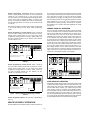
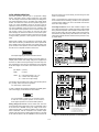
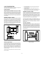
A Agilent E361xA 60W BENCH SERIES DC POWER SUPPLIES OPERATING AND SERVICE MANUAL FOR MODELS: Agilent E3614A Agilent E3615A Agilent E3616A Agilent E3617A For instruments with higher Serial Numbers than above, a change page may be included. Manual Part No. 5959-5310 July 2013 Edition 13 A CERTIFICATION Agilent Technologies certifies that this product met its published specifications at time of shipment from the factory. Agilent Technologies further certifies that its calibration measurements are traceable to the United States National Institute of Standards and Technology (formerly National Bureau of Standards), to the extent allowed by that organization's calibration facility, and to the calibration facilities of other International Standards Organization members. WARRANTY This Agilent Technologies hardware product is warranted against defects in material and workmanship for a period of 3 years from date of delivery. Agilent software and firmware products, which are designated by Agilent for use with a hardware product and when properly installed on that hardware product, are warranted not to fail to execute their programming instructions due to defects in material and workmanship for a period of 90 days from date of delivery. During the warranty period, either Agilent or Agilent Technologies will, at its option, either repair or replace products which prove to be defective. Agilent does not warrant that operation the software, firmware, or hardware shall be uninterrupted or error free. For warranty service, with the exception of warranty options, this product must be returned to the nearest service center designated by Agilent. Return to Englewood Colorado Service Center for repair in United States(1-800-258-5165). Customer shall prepay shipping charges by (and shall pay all duty and taxes) for products returned to Agilent for warranty service. Except for the products returned to Customer from another country, Agilent shall pay for return of products to Customer. Warranty services outside the country of initial purchase are included in Agilent's product price, only if Customer pays Agilent international prices (defined as destination local currency price, or U.S. or Geneva Export price). If Agilent is unable, within a reasonable time, to repair or replace any product to condition as warranted, the Customer shall be entitled to a refund of the purchase price upon return of the product to Agilent. The warranty period begins on the date of delivery or on the date of installation if installed by Agilent. LIMITATION OF WARRANTY The foregoing warranty shall not apply to defects resulting from improper or inadequate maintenance by the Customer, Customer-supplied software or interfacing, unauthorized modification or misuse, operation outside of the environmental specifications for the product, or improper site preparation and maintenance. TO THE EXTENT ALLOWED BY LOCAL LAW, NO OTHER WARRANTY IS EXPRESSED OR IMPLIED. AND AGILENT SPECIFICALLY DISCLAIMS THE IMPLIED WARRANTIES OF MERCHANTABILITY AND FITNESS FOR A PARTICULAR PURPOSE. For consumer transactions in Australia and New Zealand: The warranty terms contained in this statement, except to the extent lawfully permitted, do not exclude, restrict or modify and are in addition to the mandatory rights applicable to the sale of this product to you. EXCLUSIVE REMEDIES TO THE EXTENT ALLOWED BY LOCAL LAW, THE REMEDIES PROVIDED HEREIN ARE THE CUSTOMER'S SOLE AND EXCLUSIVE REMEDIES. AGILENT SHALL NOT BE LIABLE FOR ANY DIRECT, INDIRECT, SPECIAL, INCIDENTAL, OR CONSEQUENTIAL DAMAGES, WHETHER BASED ON CONTRACT, TORT, OR ANY OTHER LEGAL THEORY. ASSISTANCE The above statements apply only to the standard product warranty. Warranty options, extended support contacts, product maintenance agreements and customer assistance agreements are also available. Contact your nearest Agilent Technologies Sales and Service office for further information on Agilent's full line of Support Programs. SAFETY SUMMARY The following general safety precautions must be observed during all phases of operation, service, and repair of this instrument. Failure to comply with these precautions or with specific warnings elsewhere in this manual violates safety standards of design, manufacture, and intended use of the instrument. Agilent Technologies assumes no liability for the customer's failure to comply with these requirements. SAFETY SYMBOLS BEFORE APPLYING POWER. Verify that the product is set to match the available line voltage and that the correct fuse is installed. Instruction manual symbol; the product will be marked with this symbol when it is necessary for the user to refer to the instruction manual. ! GROUND THE INSTRUMENT. This product is a Safety Class I instrument (provided with a protective earth terminal). To minimize shock hazard, the instrument chassis and cabinet must be connected to an electrical ground. The instrument must be connected to the ac power supply mains through a three-conductor power cable, with the third wire firmly connected to an electrical ground(safety ground) at the power outlet. Any interruption of the protective(grounding) conductor or disconnection of the protective earth terminal will cause a potential shock hazard that could result in personal injury. If the instrument is to be energized via an external autotransformer for voltage reduction, be certain that the autotransformer common terminal is connected to the neutral(earthed pole) of the ac power lines (supply mains). or WARNING DO NOT OPERATE IN AN EXPLOSIVE ATMOSPHERE. Do not operate the instrument in the presence of flammable gases or fumes. CAUTION KEEP AWAY FROM LIVE CIRCUITS. Operating personnel must not remove instrument covers. Component replacement and internal adjustments must be made by qualified service personnel. Do not replace components with power cable connected. Under certain conditions, dangerous voltages may exist even with the power cable removed. To avoid injuries, always disconnect power, discharge circuits and remove external voltage sources before touching components. NOTE DO NOT SERVICE OR ADJUST ALONE. Do not attempt internal service or adjustment unless another person, capable of rendering first aid and resuscitation, is present. Indicate earth(ground) terminal. The WARNING sign denotes a hazard. It calls attention to a procedure, practice, or the like, which, if not correctly performed or adhered to, could result inpersonal injury. Do not proceed beyond a WARNING sign until the indicated conditions are fully understood and met. The CAUTION sign denotes a hazard. It calls attention to an operating procedure, or the like, which, if not correctly performed or adhered to, could result in damage to or destruction of part or all of the product. Do not proceed beyond CAUTION sign until the indicated conditions are fully understood and met. The NOTE sign denotes important information. It calls attention to a procedure, practice, condition or the like, which is essential to highlight. DO NOT SUBSTITUTE PARTS OR MODIFY INSTRUMENT. Because of the danger of introducing additional hazards, do not install substitute parts or perform any unauthorized modification to the instrument. Return the instrument to a Agilent Technologies Sales and Service Office for service and repair to ensure that safety features are maintained. Instruments that appear damaged or defective should be made inoperative and secured against unintended operation until they can be repaired by qualified service personnel. 1-2 DECLARATION OF CONFORMITY The Declaration of Conformity (DoC) for this instrument is available on the Agilent website. You can search the DoC by its product model or description at the web address below. http://regulations.corporate.agilent.com/DoC/search.htm Note If you are unable to search for the respective DoC, please contact your local Agilent representative. 1-3 Table of Contents SAFETY SUMMARY . . . . . . . . . . . . . . . . . . . . . . . . . . . . . . . . . . . . . . . . . . . . . . . . . . . . . . . . . . . . . . 1-2 GENERAL INFORMATION . . . . . . . . . . . . . . . . . . . . . . . . . . . . . . . . . . . . . . . . . . . . . . . . . . . . . . . . . 1-4 INTRODUCTION . . . . . . . . . . . . . . . . . . . . . . . . . . . . . . . . . . . . . . . . . . . . . . . . . . . . . . . . . . . . . . . . 1-4 SAFETY REQUIREMENTS . . . . . . . . . . . . . . . . . . . . . . . . . . . . . . . . . . . . . . . . . . . . . . . . . . . . . . . . 1-4 INSTRUMENT AND MANUAL IDENTIFICATION . . . . . . . . . . . . . . . . . . . . . . . . . . . . . . . . . . . . . . . 1-4 OPTIONS. . . . . . . . . . . . . . . . . . . . . . . . . . . . . . . . . . . . . . . . . . . . . . . . . . . . . . . . . . . . . . . . . . . . . . 1-4 ACCESSORY . . . . . . . . . . . . . . . . . . . . . . . . . . . . . . . . . . . . . . . . . . . . . . . . . . . . . . . . . . . . . . . . . . 1-4 DESCRIPTION . . . . . . . . . . . . . . . . . . . . . . . . . . . . . . . . . . . . . . . . . . . . . . . . . . . . . . . . . . . . . . . . . 1-4 SPECIFICATIONS . . . . . . . . . . . . . . . . . . . . . . . . . . . . . . . . . . . . . . . . . . . . . . . . . . . . . . . . . . . . . . . 1-5 INSTALLATION. . . . . . . . . . . . . . . . . . . . . . . . . . . . . . . . . . . . . . . . . . . . . . . . . . . . . . . . . . . . . . . . . . 1-6 INITIAL INSPECTION . . . . . . . . . . . . . . . . . . . . . . . . . . . . . . . . . . . . . . . . . . . . . . . . . . . . . . . . . . . . 1-6 Mechanical Check. . . . . . . . . . . . . . . . . . . . . . . . . . . . . . . . . . . . . . . . . . . . . . . . . . . . . . . . . . 1-6 Electrical Check . . . . . . . . . . . . . . . . . . . . . . . . . . . . . . . . . . . . . . . . . . . . . . . . . . . . . . . . . . . 1-6 INSTALLATION DATA. . . . . . . . . . . . . . . . . . . . . . . . . . . . . . . . . . . . . . . . . . . . . . . . . . . . . . . . . . . . 1-6 Location and Cooling . . . . . . . . . . . . . . . . . . . . . . . . . . . . . . . . . . . . . . . . . . . . . . . . . . . . . . . 1-6 Outline Diagram . . . . . . . . . . . . . . . . . . . . . . . . . . . . . . . . . . . . . . . . . . . . . . . . . . . . . . . . . . . 1-6 Rack Mounting . . . . . . . . . . . . . . . . . . . . . . . . . . . . . . . . . . . . . . . . . . . . . . . . . . . . . . . . . . . . 1-6 INPUT POWER REQUIREMENTS . . . . . . . . . . . . . . . . . . . . . . . . . . . . . . . . . . . . . . . . . . . . . . . . . . 1-6 Line Voltage Option Conversion . . . . . . . . . . . . . . . . . . . . . . . . . . . . . . . . . . . . . . . . . . . . . . . 1-6 Power Cord . . . . . . . . . . . . . . . . . . . . . . . . . . . . . . . . . . . . . . . . . . . . . . . . . . . . . . . . . . . . . . . 1-7 OPERATING INSTRUCTIONS . . . . . . . . . . . . . . . . . . . . . . . . . . . . . . . . . . . . . . . . . . . . . . . . . . . . . . 1-7 INTRODUCTION . . . . . . . . . . . . . . . . . . . . . . . . . . . . . . . . . . . . . . . . . . . . . . . . . . . . . . . . . . . . . . . . 1-7 TURN-ON CHECKOUT PROCEDURE . . . . . . . . . . . . . . . . . . . . . . . . . . . . . . . . . . . . . . . . . . . . . . . 1-7 OPERATING MODES . . . . . . . . . . . . . . . . . . . . . . . . . . . . . . . . . . . . . . . . . . . . . . . . . . . . . . . . . . . . . 1-8 LOCAL OPERATING MODE . . . . . . . . . . . . . . . . . . . . . . . . . . . . . . . . . . . . . . . . . . . . . . . . . . . . . . . 1-8 Constant Voltage Operaton. . . . . . . . . . . . . . . . . . . . . . . . . . . . . . . . . . . . . . . . . . . . . . . . . . . 1-8 Constant Current Operation . . . . . . . . . . . . . . . . . . . . . . . . . . . . . . . . . . . . . . . . . . . . . . . . . . 1-8 Overvoltage Protection (OVP). . . . . . . . . . . . . . . . . . . . . . . . . . . . . . . . . . . . . . . . . . . . . . . . . 1-8 CONNECTING LOADS . . . . . . . . . . . . . . . . . . . . . . . . . . . . . . . . . . . . . . . . . . . . . . . . . . . . . . . . . . . 1-8 OPERATION BEYOND RATED OUTPUT. . . . . . . . . . . . . . . . . . . . . . . . . . . . . . . . . . . . . . . . . . . . . 1-8 REMOTE OPERATING MODES . . . . . . . . . . . . . . . . . . . . . . . . . . . . . . . . . . . . . . . . . . . . . . . . . . . . 1-9 Remote Voltage Sensing . . . . . . . . . . . . . . . . . . . . . . . . . . . . . . . . . . . . . . . . . . . . . . . . . . . . 1-9 Remote Analog Voltage Programming . . . . . . . . . . . . . . . . . . . . . . . . . . . . . . . . . . . . . . . . . . 1-9 MULTIPLE-SUPPLY OPERATION . . . . . . . . . . . . . . . . . . . . . . . . . . . . . . . . . . . . . . . . . . . . . . . . . . 1-10 NORMAL PARALLEL OPERATION . . . . . . . . . . . . . . . . . . . . . . . . . . . . . . . . . . . . . . . . . . . . . . . . 1-10 AUTO-PARALLEL OPERATION . . . . . . . . . . . . . . . . . . . . . . . . . . . . . . . . . . . . . . . . . . . . . . . . . . . 1-10 NORMAL SERIES OPERATION . . . . . . . . . . . . . . . . . . . . . . . . . . . . . . . . . . . . . . . . . . . . . . . . . . . 1-11 AUTO-SERIES OPERATION . . . . . . . . . . . . . . . . . . . . . . . . . . . . . . . . . . . . . . . . . . . . . . . . . . . . . 1-12 AUTO-TRACKING OPERATON . . . . . . . . . . . . . . . . . . . . . . . . . . . . . . . . . . . . . . . . . . . . . . . . . . . 1-13 LOAD CONSIDERATIONS . . . . . . . . . . . . . . . . . . . . . . . . . . . . . . . . . . . . . . . . . . . . . . . . . . . . . . . . 1-14 PULSE LOADING . . . . . . . . . . . . . . . . . . . . . . . . . . . . . . . . . . . . . . . . . . . . . . . . . . . . . . . . . . . . . . 1-14 REVERSE CURRENT LOADING . . . . . . . . . . . . . . . . . . . . . . . . . . . . . . . . . . . . . . . . . . . . . . . . . . 1-14 OUTPUT CAPACITANCE . . . . . . . . . . . . . . . . . . . . . . . . . . . . . . . . . . . . . . . . . . . . . . . . . . . . . . . . 1-14 REVERSE VOLTAGE LOADING. . . . . . . . . . . . . . . . . . . . . . . . . . . . . . . . . . . . . . . . . . . . . . . . . . . 1-14 BATTERY CHARGING . . . . . . . . . . . . . . . . . . . . . . . . . . . . . . . . . . . . . . . . . . . . . . . . . . . . . . . . . . 1-14 1-4 GENERAL INFORMATION OPTIONS Options 0EM, 0E3 and 0E9 determine which line voltage is selected at the factory. The standard unit is configured for 115 Vac ± 10%. For information about changing the line voltage setting, see paragraph "INPUT POWER REQUIREMENTS", page 1-6. 0EM: Input power, 115 Vac ± 10%, 47-63 Hz 0E3: Input power, 230 Vac ± 10%, 47-63 Hz 0E9: Input power, 100 Vac ± 10%, 47-63 Hz 0L2: One additional manual INTRODUCTION This manual describes all models in the Agilent E361xA 60W Bench Power Supply family and unless stated otherwise, the information in this manual applies to all models. SAFETY REQUIREMENTS This product is a Safety Class I instrument, which means that it is provided with a protective earth ground terminal. This terminal must be connected to an ac source that has a 3-wire ground receptacle. Review the instrument rear panel and this manual for safety markings and instructions before operating the instrument. Refer to the Safety Summary page at the beginning of this manual for a summary of general safety information. Specific safety information is located at the appropriate places in this manual. ACCESSORY The accessory listed below may be ordered from your local Agilent Technologies Sales Office either with the power supply or separately. (Refer to the list at the rear of the manual for address.) Agilent Part No. Description 5063-9240 Rack Kit for mounting one or two 3 1/2" high supply in a standard 19" rack This power supply is designed to comply with the following safety and EMC(Electromagnetic Compatibility) requirements IEC 348: Safety Requirements for Electronic Measuring Apparatus IEC 1010-1/EN 61010: Safety Requirements for Electrical Equipment for Measurement, Control, and Laboratory Use CSA C22.2 No.231: Safety Requirements for Electrical and Electronic Measuring and Test Equipment UL 1244: Electrical and Electronic Measuring and Testing Equipment. EMC Directive 89/336/EEC: Council Directive entitled Approximation of the Laws of the Member States relating to Electromagnetic Compatibility EN 55011(1991) Group 1, Class B/CISPR 11: Limits and Methods of Radio Interference Characteristics of Industrial, Scientific, and Medical(ISM) Radio-Frequency Equipment EN 50082-1(1991) / IEC 801-2(1991): Electrostatic Discharge Requirements IEC 801-3(1984): Radiated Electromagnetic Field Requirements IEC 801-4(1988): Electrical Fast Transient/Burst Requirements ICES/NMB-001 This ISM device complies with Canadian ICES-001. Cet appareil ISM est conforme à la norme NMB-001 du Canada. The rack mount kit is needed for rack mounting of all models in the Agilent E361xA power supply because these supplies have molded feet. DESCRIPTION This power supply is suitable for either bench or rack mounted operation. It is a compact, well-regulated, Constant Voltage/Constant Current supply that will furnish full rated output voltage at the maximum rated output current or can be continuously adjusted throughout the output range. The output can be adjusted both locally from the front panel and remotely by changing the settings of the rear panel switches (See paragraph "REMOTE OPERATING MODES", page 1-9). The models in this family offer up to 60 watts of output power, with voltage up to 60 volts and current up to 6 amps as shown in Table 1. The front panel VOLTAGE control can be used to establish the voltage limit when the supply is used as a constant current source and the CURRENT control can be used to establish the output current limit when the supply is used as a constant voltage source. The supply will automatically cross over from constant voltage to constant current operation and vice versa if the output current or voltage exceeds these preset limits. INSTRUMENT AND MANUAL IDENTIFICATION The front panel includes an autoranging (E3614A singlerange) digital voltmeter and a single-range digital ammeter. Two 3 1/2 digit voltage and current displays accurately show the output voltage and current respectively. The output ratings for each model are shown in the Specifications and Operating Characteristics Table. A serial number identifies your power supply. The serial number encodes the country of manufacture, the date of the latest significant design change, and a unique sequential number. As an illustration, a serial number beginning with KR306 denotes a power supply built in 1993 (3=1 993, 4=1994, etc), 6th week manufacture in Malaysia (MY). The remaining digits of the serial number are a unique, five-digit number assigned sequentially. The OVP/CC SET switch is used to check the OVP trip voltage and current control set value. When pressing this switch, the voltage display indicates the OVP trip voltage and the current display indicates the current control set value. If a yellow Change Sheet is supplied with this manual, its purpose is to explain any differences between your instrument and the instrument described in this manual. The change sheet may also contain information for correcting errors in the manual. The power supply has both front and rear output terminals. Either the positive or negative output terminal may be 1-5 grounded or the power supply can be operated floating at up to a maximum of 240 Volts off ground. Total output voltage to ground must not exceed 240 Vdc. LINE FUSE Line Voltage 100/115 Vac 230 Vac Fuse 2.0 AT 1.0 AT SPECIFICATIONS Detailed specifications for the power supply are given in Table 1. All specifications are at front terminals with a resistive load, and local sensing unless otherwise stated. Operating characteristics provide useful, but non-warranted information in the form of the nominal performance. Agilent Part No. 2110-1393 2110-1346 Table 1. Specifications and Operating Characteristics *AC INPUT *STABILITY (OUTPUT DRIFT) An internal switch permits operation from 100, 115, or 230 Vac lines. 100 Vac ± 10%, 47-63 Hz, 163 VA, 125 W 115 Vac ± 10%, 47-63 Hz, 163 VA, 125 W 230 Vac ± 10%, 47-63 Hz, 163 VA, 125 W Maximum change in output for an 8 hours following a 30 minute warm-up under constant line, load and ambient temperature. Constant Voltage: Less than 0.1% plus 5 mV Constant Current: Less than 0.1% plus 10 mA DC OUTPUT Less than 50 μsec for output recovery to within 15 mV following a change in output current from full load to half load, or vice versa. LOAD TRANSIENT RESPONSE TIME Voltage and current can be programmed via front panel control or remote analog control over the following ranges; E3614A: 0 - 8 V, 0 - 6 A E3615A: 0 - 20 V, 0 - 3 A E3616A: 0 - 35 V, 0 - 1.7 A E3617A: 0 - 60 V, 0 - 1 A METER ACCURACY: ±(0.5% of output + 2 counts) at 25oC ± 5oC METER (PROGRAMMING) RESOLUTION Voltage: E3614A E3615A E3616A E3617A Current: E3614A E3615A E3616A E3617A *OUTPUT TERMINALS The output terminals are provided on the front and rear panel. They are isolated from the chassis and either the positive or negative terminal may be connected to the ground terminal. LOAD REGULATION Constant Voltage - Less than 0.01% plus 2 mV for a full load to no load change in output current. Constant Current - Less than 0.01% plus 250 μA for a zero to maximum change in output voltage. 10 mV 10 mV (0 to 20 V), 100 mV (above 20 V) 10 mV (0 to 20 V), 100 mV (above 20 V) 10 mV (0 to 20 V), 100 mV (above 20 V) 10 mA 10 mA 1 mA 1 mA *OVERLOAD PROTECTION A continuously acting constant current circuit protects the power supply for all overloads including a direct short placed across the terminals in constant voltage operation. The constant voltage circuit limits the output voltage in the constant current mode of operation. LINE REGULATION Constant Voltage - Less than 0.01% plus 2 mV for any line voltage change within the input rating. Constant Current - Less than 0.01% plus 250 μA for any line voltage change within the input rating. *OVERVOLTAGE PROTECTION Trip voltage adjustable via front panel control. E3614A E3615A E3616A E3617A Range: 2.5-10 V 2.5-23 V 2.5-39 V 5-65 V Margin: Minimum setting above output voltage to avoid false tripping: 4% of output + 2 V for all models PARD (Ripple and Noise) Constant Voltage: Less than 200 μV rms and 1 mV p-p (20 Hz-20 MHz). Constant Current: E3614A: Less than 5 mA rms E3615A: Less than 2 mA rms E3616A: Less than 500 μA rms E3617A: Less than 500 μA rms *REMOTE ANALOG VOLTAGE PROGRAMMING (25 ± 5oC) per degree C at 40oC-55oC. Remotely varied voltage from 0 to 10 V provides zero to maximum rated output voltage or current. Voltage: Linearity 0.5% Current: Linearity 0.5% The programming inputs are protected against input voltages up to ±40 V. *TEMPERATURE COEFFICIENT REMOTE SENSING OPERATING TEMPERATURE RANGE 0 to 40oC for full rated output. Maximum current is derated 1% Maximum change in output per oC after a 30-minute warm-up. Constant Voltage: Less than 0.02% plus 500 μV. Constant Current: E3614A: Less than 0.02% plus 3 mA E3615A: Less than 0.02% plus 1.5 mA E3616A: Less than 0.02% plus 1 mA E3617A: Less than 0.02% plus 0.5 mA Meets load-regulation specification when correcting for load-lead drops of up to 0.5 V per lead with sense wire resistance of less than 0.5 ohms per sense lead and lead lengths of less than 5 meters. 1-6 Table 1. Specifications and Operating Characteristics (Cont’d) *REMOTE PROGRAMMING SPEED DC ISOLATION Maximum time required for output voltage to change from initial value to within a tolerance band (0.1%) of the newly programmed value following the onset of a step change in the programming input voltage. Full load No load Up: E3614A: 3 msec 2 msec E3615A: 9 msec 6 msec E3616A: 85 msec 85 msec E3617A: 200 msec 200 msec Down: E3614A: 7 msec 1.6 sec E3615A: 13 msec 2.2 sec E3616A: 65 msec 1.8 sec E3617A: 200 msec 3.2 sec ± 240 Vdc maximum between either output terminal and earth ground including the output voltage. INSTALLATION instructions. *COOLING: Convection cooling is employed. *WEIGHT: 12.1 lbs/5.5 Kg net, 14.9 lbs/6.75 Kg shipping. * Operating Characteristics INITIAL INSPECTION Before shipment, this instrument was inspected and found to be free of mechanical and electrical defects. As soon as the instrument is unpacked, inspect for any damage that may have occurred in transit. Save all packing materials until the inspection is completed. If damage is found, a claim should be filed with the carrier. The Agilent Technologies Sales and Service office should be notified. Mechanical Check This check should confirm that there are no broken knobs or connectors, that the cabinet and panel surfaces are free of dents and scratches, and that the meter is not scratched or cracked. Electrical Check The instrument should be checked against its electrical specifications. Paragraph "TURN-ON CHECKOUT PROCEDURE" contains a brief checkout procedure and "PERFORMANCE TEST" in section SERVICE INFORMATION includes an instrument performance check to verify proper instrument operation. Figure 1. Outline Diagram INPUT POWER REQUIREMENTS The instrument is shipped ready for bench operation. It is necessary only to connect the instrument to a source of power and it is ready for operation. This power supply may be operated from nominal 100, 115, or 230 Vac 47-63 Hertz power source. A label on the rear panel shows the nominal input voltage set for the unit at the factory. If necessary, you can convert the supply to another nominal input voltage by following the instructions below Location and Cooling Line Voltage Option Conversion INSTALLATION DATA Line voltage conversion is accomplished by adjusting two components: the line select switch and the rear panel fuse F1. To convert the supply from one line voltage option to another, proceed as follows: This instrument is air cooled. Sufficient space should be allowed so that a free flow of cooling air can reach the sides and rear of the instrument when it is in operation. It should be used in an area where the ambient temperature does not exceed 40oC. Maximum current is derated 1% per oC at 40oC-55oC. a. Disconnect power cord. b. Turn off the supply and remove the top cover by lifting the cover upwards after taking it off from both sides of the chassis by inserting a flat-blade screwdriver into the gap on the lower rear portion of the cover. c. Set two sections of the line voltage selector switch on the PC board for the desired line voltage (see Figure 2). d. Check the rating of the fuse F1 installed in the rear panel fuse holder and replace with the correct fuse if necessary. For 100 and 115 V operation, use a time delay blow 2 A fuse and for 230 V use a time delay 1 A fuse. Outline Diagram Figure 1 is a outline diagram showing the dimensions of the instrument. Rack Mounting This instrument may be rack mounted in a standard 19-inch rack panel either by itself or alongside a similar unit. Please see ACCESSORY, page 1-4, for available rack mounting accessories. Each rack-mounting kit includes complete installation 1-7 e. Replace the cover and mark the supply clearly with a tag or label indicating the correct line voltage and fuse that is in use. 4. DISPLAY OVP/CC SET Switch: Pressing this switch causes the VOLTS display to show voltage setting for overvoltage shutdown (trip voltage) and the AMPS display to show the current control set value. Setting values are either front panel settings or remote voltage programmed settings. 5. OVP Adjust Screwdriver Control: While pressing the DISPLAY OVP/CC SET switch, rotating the control clock-wise with a small, flat-blade screwdriver increases the setting for overvoltage shutdown. 6. VOLTS Display: Digital display of actual output voltage, or OVP shutdown setting. 7. AMPS Display: Digital display of actual output current, or output-current setting. 8. CV LED Indicator: Output voltage is regulated when lighted. This means the power supply is operating in the constant voltage mode. 9. CC LED Indicator: Output current is regulated when lighted. This means the power supply is operating in the constant current mode. 10. OVP LED Indicator: Output is shutdown by the occurrence of an overvoltage when lighted. Removing the cause of overvoltage and turning the power off, then on, resets the power supply. Figure 2. Line Voltage Selector (set for 115 Vac) Power Cord To protect operating personnel, the instrument should be grounded. This instrument is equipped with a three conductor power cord. The third conductor is the ground conductor and when the power cord is plugged into an appropriate receptacle, the supply is grounded. The power supply was shipped with a power cord for the type of outlet used at your location. If the appropriate cord was not included, contact your nearest Agilent Sales Office to obtain the correct cord. TURN-ON CHECKOUT PROCEDURE The following checkout procedure describes the use of the front panel controls and indicators illustrated in Figure 3 and ensures that the supply is operational: OPERATING INSTRUCTIONS LOCAL MASTER _ + + _ + _ INTRODUCTION This section explains the operating controls and indicators and provides information on many operating modes possible with your instrument. The front panel controls and indicators are illustrated in Figure 3. M/S 1 M/S 2 SLAVE CV CC SENSE +S OUT -S CV CC VREF A1 A2 A3 A4 A5 REMOTE Figure 4. Switch Settings of Rear-Panel Control for TurnOn Checkout a. Disconnect power cord. b. Check that the rear-panel switch settings are as shown in Figure 4. c. Check that the rear panel label indicates that the supply is set to match your input line voltage (If not, refer to "Line Voltage Option Conversion".). d. Check that the fuse on the rear panel is correct for your line voltage. e. Connect the power cord and push the LINE switch to ON. f. While pressing OVP/CC SET switch, verify that the OVP shutdown is set above 8.0, 20.0, 35.0, or 60.0 Vdc for E3614A, E3615A, E3616A, or E3617A respectively. If not, turn up OVP Adjust with a small flat-blade screwdriver. g. Turn VOLTAGE control fully counter clockwise to ensure that the output of VOLTS display decreases to 0 Vdc, then fully clockwise to ensure that output voltage increases to the maximum output voltage. h. While pressing OVP/CC SET switch, turn the CURRENT control fully counter clockwise and then fully clockwise to ensure Figure 3. Front-Panel Controls and Indicators 1. LINE Switch: Pressing this switch turns the supply on, or off. 2. VOLTAGE Control: Clockwise rotation increases output voltage. 3. CURRENT Control: Clockwise rotation increases output current. 1-8 that the current limit value can be set from zero to maximum rated value. False OVP shutdowns may occur if you set the OVP shutdown too close to the supply's operating voltage. Set the OVP shutdown voltage 4% of output +2.0 V or more above the output voltage to avoid false shutdowns from load-induced transients. OPERATING MODES The setting of the rear panel switch determines the operating modes of the power supply. The local operating mode is set so the power supply senses the output voltage directly at the output terminals (local sensing) for operation using the front panel controls (local programming). Other operating modes are: remote voltage sensing and remote programming of output voltage and current using external voltages. Adjusting OVP. Follow this procedure to adjust the OVP shutdown voltage. a. With the VOLTAGE control fully counter clockwise, turn on the power supply. b. While depressing DISPLAY OVP/CC SET switch, adjust the OVP Adjust control to the desired OVP shutdown using a small, flat-blade screwdriver. c. Follow the procedure for CC or CV operaton to set the output voltage and current LOCAL OPERATING MODE The power supply is shipped from the factory configured in the local operating mode. Local operating mode requires the switch settings of the rear panel, as shown in Figure 4. The power supply provides constant voltage(CV) or constant current(CC) output. Resetting OVP. If OVP shutdown occurs, reset the supply by turning power off. Wait one or more seconds, and turn power on again. If OVP shutdown continue to occur, check the connections to the load and sense terminals, and check the OVP limit setting.. Constant Voltage Operaton To set up a power supply for constant voltage operation, proceed as follows: a. Turn on the power supply and adjust 10-turn VOLTAGE control for desired output voltage (output terminals open). b. While depressing DISPLAY OVP/CC SET switch, adjust 10turn CURRENT control for the desired current limit. c. With power off connect the load to the output terminals. d. Turn on the power supply. Verify that CV LED is lighted. During actual operation, if a load change causes the current limit to be exceeded, the power supply will automatically cross over to constant current mode and the output voltage will drop proportionately. Strong electrostatic discharge to power supply can make OVP trip and eventually crowbar the output, which can effectively protect output loads from the hazardous ESD current. CONNECTING LOADS The output of the supply is isolated from earth ground. Either output terminal may be grounded or the output can be floated up to 240 volts off ground. Total output voltage to ground must not exceed 240 Vdc. Constant Current Operation To set up a power supply for constant current operation, proceed as follows: Each load should be connected to the power supply output terminals using separate pairs of connecting wires. This will minimize mutual coupling effects between loads and will retain full advantage of the low output impedance of the power supply. Each pair of connecting wires should be as short as possible and twisted or shielded to reduce noise pick-up. (If a shield is used, connect one end to the power supply ground terminal and leave the other end unconnected.) a. Turn on power supply. b. While depressing DISPLAY OVP/CC SET switch, adjust CURRENT control for the desired output current. c. Turn up the VOLTAGE control to the desired voltage limit. d. With power off connect the load to the output terminal. e. Turn on power supply and then verify that CC LED is lighted. (If CV LED is lighted, choose a higher voltage limit. A voltage setting that is greater than the current setting multiplied by the load resistance in ohms is required for CC operation.) During actual operation, if a load change causes the voltage limit to be exceeded, the power supply will automatically cross over to constant voltage operation at the preset voltage limit and output current will drop proportionately. If load considerations require that the output power distribution terminals be remotely located from the power supply, then the power supply output terminals should be connected to the remote distribution terminals via a pair of twisted or shielded wires and each load separately connected to the remote distribution terminals. For this case, remote sensing should be used (See paragraph "Remote Voltage Sensing"). Overvoltage Protection (OVP) Adjustable overvoltage protection guards your load against overvoltage. When the voltage at the output terminals increases (or is increased by an external source) to the OVP shutdown voltage as set by the OVP ADJUST control, the supply's OVP circuit disables the output causing the output voltage and current to drop to zero. During OVP shutdown the OVP LED lights. OPERATION BEYOND RATED OUTPUT The output controls can adjust the voltage or current to values up to 5% over the rated output. Although the supply can be operated in the 5% overrange region without being damaged, it can not be guaranteed to meet all of its performance specifications in this region. 1-9 REMOTE OPERATING MODES leads. Ground the shield at the power supply end only. Do not use the shield as one of the sensing conductors. Remote operating modes discussed below are remote voltage sensing and remote voltage programming. You can set up the unit for remote operating modes by changing the settings of the rear panel switch and connecting the leads from the rear panel terminals to the load or the external voltage. Solid conductors of 0.75 Stability. When the supply is connected for remote sensing, it is possible for the impedance of the load wires and the capacitance of the load to form a filter, which will become part of the supply's CV feedback loop. The extra phase shift created by this filter can degrade the supply's stability and can result in poor transient response performance or loop stability. In extreme cases, it can cause oscillations. Keep the leads as short as possible and twist the leads of the load to eliminate the load lead inductance and keep the load capacitance as small as possible.The load leads should be of the largest diameter practical, heavy enough to limit the voltage drop in each lead to 0.5 volts. to 1.5 mm2 can be connected to the rear panel terminals by simply push fitting. Thinner wires or conductors are inserted into the connection space after depressing the orange opening lever. Turn off the supply while making changes to rear panel switch settings or connections. This avoids the possibility of damage to the load and OVP shutdown from unintended output. The sense leads are part of the supply's programming feedback control loop. Accidental open-connections of sense or load leads during remote sensing operation have various unwanted effects. Provide secure, permanent connections-especially for the sense leads. Remote Voltage Sensing Remote voltage sensing is used to maintain good regulation at the load and reduce the degradation of regulation that would occur due to the voltage drop in the leads between the power supply and the load. By connecting the supply for remote voltage sensing, voltage is sensed at the load rather than at the supply's output terminals. This will allow the supply to automatically compensate for the voltage drop in the load leads and improve regulation. During remote sensing setup, it is strongly recommended to power off (by presssing power ON/OFF button) the power supply to avoid undesirable damage to the load or the power supply. l When the supply is connected for remote sensing, the OVP circuit senses the voltage at the sense leads and not the main output terminals. LOCAL MASTER Remote voltage sensing compensates for a voltage drop of up to 0.5 V in each load, and there may be up to a 0.1 V drop between the output terminal and the internal sensing resistor, at which point the OVP circuit is connected. Therefore, the voltage sensed by the OVP circuit could be as much as 1.1 V more than the voltage being regulated at the load. It may be necessary to re-adjust the OVP trip voltage when using remote sensing. M/S 1 M/S 2 CV CC SLAVE _ + SENSE +S OUT + -S _ CV + CC _ VREF A1 A2 A3 A4 A5 REMOTE + LOAD _ NOTE: Twist sense leads and load leads CV Regulation. Notice that any voltage drop in the sense leads adds directly to the CV load regulation. In order to maintain the specified performance, keep the sense lead resistance to 0.5 ohms per lead or less. Figure 5. Remote Voltage Sensing Remote Analog Voltage Programming Remote analog voltage programming permits control of the regulated output voltage or current by means of a remotely varied voltage. The programming (external) voltage should not exceed 10 volts. The stability of the programming voltages directly affects the stability of the output. The voltage control on the front panel is disabled during remote analog programming. Remote Sensing Connections. Remote sensing requires changing settings of the rear panel switch and connecting the load leads from + and - output terminals to the load and connecting the sense leads from the +S and -S terminals to the load as shown in Figure 5. Observe polarity when connecting the sensing leads to the load. The supply includes clamp circuits to prevent it from supplying more than about 120% of rated output voltage or current when the remote programming voltage is greater than 10 Vdc. Do not intentionally operate the supply above 100% rated output. Limit your programming voltage to 10 Vdc. Output Noise. Any noise picked up on the sense leads will appear at the supply's output voltage and may degrade CV load regulation. Twist the sense leads to minimize the pickup of external noise and run them parallel and close to the load leads. In noisy environments, it may be necessary to shield the sense 1-10 Remote Programming Connections. Remote programming requires changing settings of the switch and connecting external voltages to + and - terminals of "CV" or "CC" on the rear panel. Any noise picked up on the programming leads will appear on the supply's output and may degrade regulation. To reduce noise pick-up, use a twisted or shielded pair of wires for programming, with the shield grounded at one end only. Do not use the shield as a conductor. put current while normal series and auto-series provides increased output voltage. Auto-tracking provides single control of output voltage of more than one supply. You can set up the unit for multiplesupply operation by changing the settings of the rear panel switch and connecting the leads from the rear panel terminals to the load. Solid conductors of 0.75 to 1.5 mm2 can be connected to the rear panel terminals by simply push fitting. Thinner wires or conductors are inserted into the connection space after depressing the orange opening lever. Notice that it is possible to operate a power supply simultaneously in the remote sensing and the remote analog programming modes. NORMAL PARALLEL OPERATION Two or more power supplies being capable of CV/CC automatic cross over operation can be connected in parallel to obtain a total output current greater than that available from one power supply. The total output current is the sum of the output currents of the individual power supplies. The output of each power supply can be set separately. The output voltage controls of one power supply should be set to the desired output voltage; the other power supply should be set for a slightly higher output voltage. The supply with the higher output voltage setting will deliver its constant current output, and drop its output voltage until it equals the output of the other supply, and the other supply will remain in constant voltage operation and only deliver that fraction of its rated output current which is necessary to fulfill the total load demand. Figure 8 shows the rear panel switch settings and terminal connections for normal parallel operation of two supplies. Remote Programming, Constant Voltage. Figure 6 shows the rear panel switch settings and terminal connections for remotevoltage control of output voltage. A 1 Vdc change in the remote programming voltage produces a change in output voltage (voltage gain) as follows: E3614A: 0.8 Vdc, E3615A: 2 Vdc, E3616A: 3.5 Vdc, E3617A: 6 Vdc LOCAL MASTER M/S 1 M/S 2 CV CC SLAVE _ + SENSE OUT +S + -S _ _ + CV CC VREF A1 A2 A3 A4 A5 REMOTE NOTE: POWER SUPPLY See the supplementary Manual, if you are not using Figure 6. Remote Voltage Programming, Constant Voltage M/S 1 M/S 2 SLAVE Remote Programming, Constant Current. Figure 7 shows the rear panel switch settings and terminal connections for remotevoltage control of output current. A 1 Vdc change in the remote programming voltage produces a change in output current (current gain) as follows: E3614A: 0.6 Adc, E3615A: 0.3 Adc, E3616A: 0.17 Adc, E3617A: 0.1 Adc LOCAL MASTER LOCAL MASTER isolated programming voltage source. _ + + _ CC SENSE REMOTE OUT +S + -S _ + _ CC VREF A1 A2 A3 A4 A5 CV LOAD POWER SUPPLY LOCAL MASTER M/S 1 M/S 2 SLAVE _ + CV _ + CV CC REMOTE + SENSE +S _ OUT + -S CV _ + _ CC VREF A1 A2 A3 A4 A5 Figure 8. Normal Parallel Operation of Two Supplies AUTO-PARALLEL OPERATION M/S 1 M/S 2 SLAVE CV CC SENSE +S OUT -S CV CC VREF A1 A2 A3 A4 Auto-parallel operation permits equal current sharing under all load conditions, and allows complete control of output current from one master supply. The control unit is called the master; the controlled units are called slaves. Normally, only supplies having the same model number should be connected for auto-parallel operation, since the supplies must have the same voltage drop across the current monitoring resistor at full current rating. The output current of each slave is approximately equal to the master's. Figure 9 and Figure 10 show the rear panel switch settings and terminal connections for auto-parallel operation of two supplies and three supplies. A5 REMOTE NOTE: See the supplementary Manual, if you are not using isolated programming voltage source. Figure 7. Remote Voltage Programming, Constant Current Remote Programming Speed. See the table of Specifications, page 1-5. MULTIPLE-SUPPLY OPERATION Normal parallel and auto-parallel operation provides increased out- 1-11 Setting Voltage and Current. Turn the slave unit's CURRENT control fully clockwise. Adjust the master unit's controls to set the desired output voltage and current. The master supply operates in a completely normal fashion and may be set up for either constant voltage or constant current operation as required. Verify that the slave is in CV operation. gramming according to the remote-programming instructions. MASTER POWER SUPPLY For auto-parallel operation of two supplies, the combined output voltage is the same as the master unit's voltage setting, and the combined output current is two times the master unit's current. In general, for two supplies, the auto-parallel output current(Io) is M/S 1 M/S 2 CV SLAVE CC _ + LOCAL MASTER SENSE +S OUT -S M/S 2 CV SLAVE CC _ + LOCAL MASTER M/S 1 SENSE OUT +S -S M/S 1 M/S 2 SLAVE CV CC SENSE REMOTE OUT +S + -S _ + M/S 1 M/S 2 SLAVE CV CC + SENSE REMOTE +S _ OUT + -S CV _ + SENSE OUT +S -S _ + _ CC VREF A1 A2 A3 A4 A5 CV REMOTE Series operation of two or more power supplies can be accomplished up to the output isolation rating of any one supply to obtain a higher voltage than that available from a single supply. Series connected supplies can be operated with one load across both supplies or with a separate load for each supply. These power supplies have a reverse polarity diode connected across the output terminals so that if operated in series with other supplies, damage will not occur if the load is short-circuited or if one supply is turned on separately from its series partners. When this connection is used, the output voltage is the sum of the voltages of the individual supplies. Each of the individual supplies must be adjusted in order to obtain the total output voltage. Figure 11 shows the rear panel switch settings and terminal connections for normal series operation of two supplies. _ LOAD LOCAL CC + NORMAL SERIES OPERATION SLAVE POWER SUPPLY MASTER CC VREF A1 A2 A3 A4 A5 Figure 10. Auto-Parallel Operation of Three Supplies CC VREF A1 A2 A3 A4 A5 CV CV SLAVE MASTER POWER SUPPLY _ M/S 2 _ + _ CV _ + LOCAL MASTER M/S 1 + REMOTE SLAVE POWER SUPPLY Proportional currents from auto-paralleled units require equal load-lead voltage drops. Connect each supply to the load using separate pairs of wire with length chosen to provide equal voltage drops from pair to pair. If this is not feasible, connect each supply to a pair of distribution terminals using equal- voltage-drop wire pairs, and then connect the distribution terminals to the load with a single pair of leads. + CC VREF A1 A2 A3 A4 A5 CV REMOTE SLAVE POWER SUPPLY LOCAL _ + _ LOAD Io = Im + Is = 2Im where Im = master unit's output current Is = slave unit's output current MASTER + _ CC VREF A1 A2 A3 A4 A5 POWER SUPPLY Figure 9. Auto-Parallel Operation of Two Supplies LOCAL MASTER Overvoltage Protection. Adjust the desired OVP shutdown limit using the master unit's OVP Adjust control. Set the slave units' OVP limits above the master's. When a master-unit shuts down, the master programs the slave units to zero voltage output. If a slave unit shuts down, it shuts only itself down. If the required current is great enough, the master will switch from CV to CC operation. M/S 1 M/S 2 SLAVE CV CC _ + SENSE REMOTE OUT +S + -S _ + _ CC VREF A1 A2 A3 A4 A5 CV LOAD POWER SUPPLY LOCAL MASTER + Remote Sensing. To remote sense with auto-parallel operation, connect remote-sense leads only to the master unit according to the remote-sensing instructions. Remote Analog Voltage Programming. To remote program with auto-parallel operation, set up only the master unit for remote pro- M/S 1 M/S 2 SLAVE CV CC REMOTE SENSE +S _ OUT + -S CV _ + _ CC VREF A1 A2 A3 A4 A5 Figure 11. Normal Series Operation of Two Supplies 1-12 AUTO-SERIES OPERATION above the master unit's current setting to avoid having the slave switch to CC operation. Auto-series operation permits equal or proportional voltage sharing, and allows control of output voltage from one master unit. The voltage of the slaves is determined by the setting of the front panel VOLTAGE control on the master and voltage divider resistor. The master unit must be the most positive supply of the series. The output CURRENT controls of all series units are operative and the current limit is equal to the lowest setting. If any output CURRENT controls are set too low, automatic cross over to constant current operation will occur and the output voltage will drop. Figure 12 and Figure 13 show the rear panel switch settings and terminal connections for Auto-series operation of two supplies and three supplies. This mode can also give ±voltage tracking operation of two supplies with two separate loads. When in CC operation the combined output current is the same as the master unit's current setting, and when in CV operation the combined output voltage is the sum of the master unit's and the slave unit's output voltages. Overvoltage Protection. Set the OVP shutdown voltage in each unit so that it shuts down at a voltage higher than its output voltage during auto-series operation. When a master unit shuts down, it programs any slave units to zero output. When a slave unit shuts down, it shuts down only itself (and any slaves below it in the stack). The master (and all slaves above the shut-down slave) continues to supply output voltage. Mixed model numbers may be employed in auto-series combination without restriction, provided that each slave is specified as being capable of auto-series operation. If the master supply is set up for constant current operation, then the master-slave combination will act as a composite constant current source. MASTER POWER SUPPLY LOCAL MASTER M/S 1 M/S 2 SLAVE CV CC _ + SENSE OUT +S REMOTE _ + -S CV + _ CC VREF A1 A2 A3 A4 A5 LOAD R1 R2 SLAVE POWER SUPPLY Total output voltage to ground must not exceed 240 Vdc. LOCAL MASTER Determining Resistors. External resistors control the fraction (or multiple) of the master unit's voltage setting that is supplied from the slave unit. Notice that the percentage of the total output voltage contributed by each supply is independent of the magnitude of the total voltage. For two units in auto-series the ratio of R1 to R2 is M/S 1 M/S 2 SLAVE CV CC _ + SENSE OUT +S REMOTE _ + -S CV + _ CC VREF A1 A2 A3 A4 A5 Figure 12. Auto-Series Operation of Two Supplies (R1+R2)/R1 = (Vo/Vm) R2/R1 = (Vs/Vm) MASTER POWER SUPPLY Where M/S 1 For example, using the E3617A as a slave unit and putting R2=50 kΩ (1/4 watt), then from the above equations, R1 = R2(Vm/Vs) = 50(Vm/Vs) kΩ M/S 2 + LOCAL MASTER Vo = auto-series voltage = Vs + Vm Vm = master unit's output voltage Vs = slave unit's output voltage CV SLAVE CC SENSE +S _ OUT + -S CV _ + _ CC VREF A1 A2 A3 A4 A5 REMOTE LOAD R1 SLAVE POWER SUPPLY(S1) + LOCAL MASTER _ + R2 _ + _ In order to maintain the temperature coefficient and stability performance of the supply, choose stable, low noise resistors. M/S 1 M/S 2 CV SLAVE CC SENSE +S OUT -S CV CC VREF A1 A2 A3 A4 A5 REMOTE R3 It is recommended to connect a 0.1 μF capacitor in parallel with R2 in two supplies operation or R2 and R4 in three supplies operation to ensure the stable operation. SLAVE POWER SUPPLY(S2) Setting Voltage and Current. Use the master unit's controls to set the desired output voltage and current. The VOLTAGE control of the slave unit is disabled. Turning the voltage control of the master unit will result in a continuous variation of the output of the series combination, with the contribution of the master's output voltage to that of the slave's voltage always remaining in the ratio of the external resistors. Set the CURRENT control of slave unit M/S 1 M/S 2 SLAVE + LOCAL MASTER CV CC SENSE +S OUT _ + -S CV R4 _ + _ CC VREF A1 A2 A3 A4 A5 REMOTE R2 R2 R4 ) Vo=Vm(1+ + R1 R1 R3 Where Vo = Auto-Series voltage = Vm + Vs1 + Vs2 Vm = master unit's output voltage Vs1 = slave(S1) unit's output voltage Vs2 = slave(S2) unit's output voltage Figure 13. Auto-Series Operation of Three Supplies 1-13 Remote Sensing. To remote sense with auto-series operation, set SENSE switch of the master unit and set SENSE switch of the slave unit to remote. Remote Analog Programming. To simultaneously remote program both units' output voltages, set up only the master unit for remote voltage programming according to the remote programming instructions. To vary the fraction of the output voltage contribution by the slave unit, connect a variable resistor in place of R2 in two units operation. To independently remote program each unit's output current setting, set up each unit for remote control of output current according to the instructions under "Remote Programming, Constant Current" paragraph. Remote Analog Voltage Programming. To remote analog program with auto-series operation, connect program (external) voltages to the "CV" or "CC"" terminal of the master unit and set "CV" or "CC" switch of the master unit to remote. AUTO-TRACKING OPERATON Auto-tracking operation of power supplies is similar to auto-series operation except that the master and slave supplies have the same output polarity with respect to a common bus or ground. This operation is useful where simultaneous turn-up, turn-down or proportional control of all power supplies is required. MASTER POWER SUPPLY LOCAL MASTER M/S 1 M/S 2 SLAVE Figure 14 and Figure 15 show two and three supplies connected in auto-tracking with their negative output terminals connected together as a common or ground point. For two units in autotracking a fraction R2/(R1+R2) of the output of the master supply is provided as one of the inputs to the comparison amplifier of the slave supply, thus controlling the slave's output. The master supply in an auto-tracking operation must be the positive supply having the largest output voltage. Turn-up and turn-down of the power supplies are controlled by the master supply. In order to maintain the temperature coefficient and stability specifications of the power supply, the external resistor should be stable, low noise, low temperature. CV CC _ + SENSE OUT +S REMOTE + -S _ + _ CC VREF A1 A2 A3 A4 A5 CV LOAD R1 R2 LOAD SLAVE POWER SUPPLY LOCAL MASTER M/S 1 M/S 2 SLAVE CV CC _ + SENSE OUT +S REMOTE + -S CV _ + _ CC VREF A1 A2 A3 A4 A5 Figure 14. Auto-Tracking Operation of Two Supplies Determining Resistors. External resistors control the fraction of the master unit's voltage that is supplied from the slave unit. For two units in auto-tracking the ratio R1 and R2 is MASTER POWER SUPPLY R2/(R1+R2 = (Vs/Vm) Where Vm = master output voltage Vs = slave output voltage M/S 1 M/S 2 + LOCAL MASTER CV SLAVE CC SENSE +S _ OUT + -S CV _ + _ CC VREF A1 A2 A3 A4 A5 REMOTE LOAD Setting Voltage and Current. Use the master unit's VOLTAGE control to set the output voltage from both units. When the master is in CV operation, the master's output voltage(Vm) is the same as its voltage setting, and the slave's output voltage for two units operation is Vm(R2/(R1+R2)). The VOLTAGE control of the slave unit is disabled. Set the CURRENT controls of master and slave units above the required currents to assure CV operation of master and slave units. M/S 1 M/S 2 + LOCAL MASTER It is recommended to connect a 0.1 μF capacitor in parallel with R2 in two supplies operation or R2 and R4 in three supplies operation to ensure the stable operation. CV SLAVE CC SENSE +S M/S 2 -S CV CC VREF A1 A2 A3 A4 A5 CV SLAVE R2 Vs1 = Vm R1+ R2 R4 Vs2 = Vs1 R3+ R4 CC R3 LOAD + LOCAL MASTER M/S 1 OUT R2 _ + _ + _ REMOTE SLAVE POWER SUPPLY(S2) Overvoltage Protection. Set the OVP shutdown voltage in each unit so that it shuts down at a voltage higher than its output voltage during auto-tracking operation. When a master unit shuts down, it programs any slave units to zero output. When a slave unit shuts down, it shuts down only itself. R1 LOAD SLAVE POWER SUPPLY(S1) SENSE +S OUT R4 _ + _ + _ -S CV CC VREF A1 A2 A3 A4 A5 REMOTE Where Vm = masters unit's output voltage Vs1 = slave(S1) unit's output voltage Vs2 = slave(S2) unit's output voltage Figure 15. Auto-Tracking Operation of Three Supplies Remote Sensing. To include remote sensing with auto-tracking operation independently, set up each unit for remote sensing according to the remote-sensing instructions under previous paragraph. 1-14 LOAD CONSIDERATIONS a. The output impedance of the power supply decreases with increasing frequency. b. The recovery time of the output voltage is longer for load resistance changes. c. A large surge current causing a high power dissipation in the load occurs when the load resistance is reduced rapidly. This section provides information on operating your supply with various types of loads connected to its output. PULSE LOADING The power supply will automatically cross over from constantvoltage to constant current operation in response to an increase (over the preset limit) in the output current. Although the preset limit may be set higher than the average output current, high peak currents (as occur in pulse loading) may exceed the preset current limit and cause cross over to occur. If this cross over limiting is not desired, set the preset limit for the peak requirement and not the average. REVERSE VOLTAGE LOADING A diode is connected across the output terminals with reverse polarity. This diode protects the output electrolytic capacitors and the series regulator transistors from the effects of a reverse voltage applied across the output terminals. For example, in series operation of two supplies, if the AC is removed from one supply, the diode prevents damage to the unenergized supply which would otherwise result from a reverse polarity voltage. REVERSE CURRENT LOADING An active load connected to the power supply may actually deliver a reverse current to the power supply during a portion of its operating cycle. An external source can not be allowed to pump current into the supply without loss of regulation and possible damage to the output capacitor of the power supply. To avoid these effects, it is necessary to preload the supply with a dummy load resistor so that the power supply delivers current through the entire operating cycle of the load devices. Since series regulator transistors cannot withstand reverse voltage, another diode is connected across the series transistor. This diode protects the series regulators in parallel or auto-parallel operation if one supply of the parallel combination is turned on before the other. BATTERY CHARGING The power supply's OVP circuit contains a crowbar SCR, which effectively shorts the output of the supply whenever the OVP trips. If an external voltage source such as a battery is connected across the output, and OVP inadvertently triggered, the SCR will continuously sink a large current from the source; possibly damaging the supply. To avoid this a diode must be connected in series with the output as shown in Figure 17. Figure 16. Reverse Current Loading Solution Figure 17. Recommended Protection Circuit for Battery Charging OUTPUT CAPACITANCE An internal capacitor, connected across the output terminals of the power supply, helps to supply high-current pulses of short duration during constant voltage operation. Any capacitance added externally will improve the pulse current capability, but will decrease the safety provided by the current limiting circuit. A high-current pulse may damage load components before the average output current is large enough to cause the current limiting circuit to operate. The effect of the output capacitor during constant current operation are as follows: 1-15 www.agilent.com Contact us To obtain service, warranty or technical support assistance, contact us at the following phone numbers: United States: (tel) 800 829 4444 (fax) 800 829 4433 Canada: (tel) 877 894 4414 (fax) 800 746 4866 China: (tel) 800 810 0189 (fax) 800 820 2816 Europe: (tel) 31 20 547 2111 Japan: (tel) (81) 426 56 7832 (fax) (81) 426 56 7840 Korea: (tel) (080) 769 0800 (fax) (080) 769 0900 Latin America: (tel) (305) 269 7500 Taiwan: (tel) 0800 047 866 (fax) 0800 286 331 Other Asia Pacific Countries: (tel) (65) 6375 8100 (fax) (65) 6755 0042 Or visit Agilent worlwide Web at: www.agilent.com/find/assist Product specifications and descriptions in this document are subject to change without notice. © Agilent Technologies, Inc. 2002–2013 Printed in Malaysia Thirteenth Edition, July 12, 2013 5959-5310 Agilent Technologies