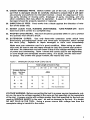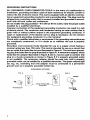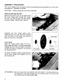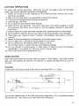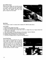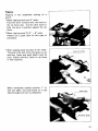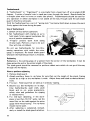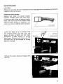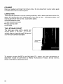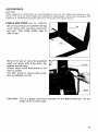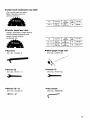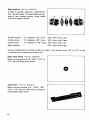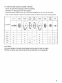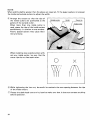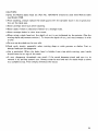
1
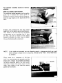
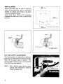
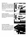
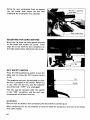
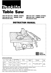
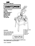
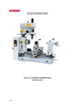
Table Saw
210 mm (8-114") MODEL 2708
INSTRUCTION MANUAL
SPEC I F ICATIONS
5/8"
Cutting capacities
Blade
diameter
Arbor hole
I
210"
(8-1/4")
1
N o load speed
I
4,500 R/min.
1
64 mm
(2-1/2")
Table size
45"
9 0"
I
41 mm
(1-5/8")
Dimensions ( L x W x
HI
460 m m x 660 mm x 375 mm
(18-1/8') x 126") x (14-3/4")
(W x L)
1
I
1
660 mm x 460 mm
(26") x ( 1 8-1/8")
Net weight
17 kg (37.5 Ibs)
~~
Manufacturer reserves the right t o change specifications o f parts and accessories wlthout notice.
Note: Specifications o f parts and accessories may differ f r o m country t o country.
BEFORE CONNECTING YOUR TOOL
TO A POWER SOURCE
Be sure you have read all
GENERAL POWER TOOL SAFETY RULES
GENERAL SAFETY PRECAUTIONS
1. KNOW YOUR POWER TOOL. Read the owner’s manual carefully. Learn the
tools applications and limitations, as well as the specific potential hazards
peculiar to it.
2. KEEP GUARDS IN PLACE and in working order.
3. REMOVE ADJUSTING KEYS AND WRENCHES. Form habit of checking to see
that keys and adjusting wrenches are removed from tool before turning it on.
4. KEEP WORK AREA CLEAN. Cluttered areas and benches invite accidents.
5. DON’T USE IN DANGEROUS ENVIRONMENT. Don’t use power tools in damp
or wet locations, or expose them to rain. Keep work area well lighted.
6. KEEP CHILDREN AWAY. All visitors should be kept safe distance from work
area.
7. MAKE WORKSHOP CHILD PROOF with padlocks, master switches, or by
removing starter keys.
8. DON’T FORCE TOOL. It will do the job better and safer at the rate for which it
was designed.
9. USE RIGHT TOOL. Don’t force tool or attachment to do a job for which it was
designed. Don’t use tool for purpose not intended; for example, don’t use circular saw for cutting tree limbs or logs.
10. WEAR PROPER APPAREL.
No loose clothing, gloves, neckties, rings,
bracelets, or other jewelry to get caught in moving parts. Nonslip footwear is
recommended. Wear protective hair covering to contain long hair.
11. ALWAYS USE SAFETY GLASSES. Also use face or dust mask if cutting operation is dusty. Everyday eyeglasses only have impact resistant lenses, they
are NOT safety glasses.
12. SECURE WORK. Use clamps or a vise to hold work when practical. It’s safer
than using your hand and it frees both hands to operate tool.
13. DON’T OVERREACH. Keep proper footing and balance at all times.
14. MAINTAIN TOOLS WITH CARE. Keep tools sharp and clean for best and
safest performance. Follow instructions for lubricating and changing accessories.
15. DISCONNECT TOOLS before servicing; when changing accessories such as
blades or adjusting guides.
16. REDUCE THE RISK OF UNINTENTIONAL STARTING. Make sure switch is in off
position before plugging in.
17. USE RECOMMENDED ACCESSORIES. Consult the owner’s manual for recommended accessories. The use of improper accessories may cause risk of
injury to persons.
18. NEVER STAND ON TOOL. Serious injury could occur if the tool is tipped or if
the cutting tool is accidentally contacted.
2
19. CHECK DAMAGED PARTS. Before further use of the tool, a guard or other
part that is damaged should be carefully checked to ensure that it will operate properly and perform its intended function check for alignment of moving parts, binding of moving parts, breakage of parts, mounting, and any
other conditions that may affect its operation. A guard or other part that is
damaged should be properly repaired or replaced.
20. DIRECTION OF FEED. Feed works into a blade against the direction of rotation of the blade only.
-
21. NEVER LEAVE TOOL RUNNING UNATTENDED. TURN POWER OFF.
leave tool until it comes to a complete stop.
Don’t
22. PROPER GROUNDING. This tool should be grounded while in use to protect
the operator from electric shock.
23. EXTENSION CORDS. Use only three-wire extension cords which have
three-prong grounding-type plugs and three-pole receptacles which accept
the tool’s plug. Replace or repair damaged or worn cord immediately.
Make sure your extension cord is in good condition. When using an extension cord, be sure to use one heavy enough to carry the current your product
will draw. An undersized cord will cause a drop in line voltage resulting in loss
of power and overheating. Table 1 shows the correct size to use depending
on cord length and nameplate ampere rating. If in doubt, use the next heavier gauge. The smaller the gauge number, the heavier the cord.
1rable 1. MINIMUM 3AUGE FOR CORD SETS
~~
I
Total Length of Cord in Feet
Ampere Rating
Not More
Than
More
Than
0
-
6
18
16
16
14
6
10
18
16
14
12
10
-
12
16
16
14
12
12
- 16
14
12
Not recommended
VOLTAGE WARNING: Before connecting the tool to a power source (receptacle, outlet, etc.) be sure the voltage supplied is the same as that specified on the nameplate
of the tool. A power source with voltage greater than that specified for the tool can
result in SERIOUS INJURY to the user as well as damage to the tool. If in doubt,
DO NOT PLUG IN THE TOOL. Using a power source with voltage less than the
nameplate rating is harmful to the motor.
-
3
GROU N DING INSTRUCTI0NS
ALL GROUNDED, CORD-CONNECTED TOOLS: In the event of a malfunction or
breakdown, grounding provides a path of least resistance for electric current t o
reduce the risk of electric shock. This tool is equipped w i t h an electric cord having an equipment-grounding conductor and a grounding plug. The plug must be
plugged into a matching outlet that is properly installed and grounded in accordance w i t h all local codes and ordinances.
Do not modify the plug provided - if it will not fii the outlet, have the proper outlet
installed by a qualified electrician.
Improper connection of the equipment-grounding conductor can result in a risk
of electric shock. The conductor w i t h insulation having an outer surface that is
green w i t h or without yellow stripes is the equipment-grounding conductor. If
repair or replacement of the electric cord or plug is necessary, do not connect
the equipment-grounding conductor t o a live terminal.
Check w i t h a qualified electrician or serviceman if the grounding instructions are
not completely understood, or if in doubt as t o whether the tool is properly
grounded.
Grounded, cord-connected tools intended for use on a supply circuit having a
nominal rating less than 150 volts: This tool is intended for use on a circuit that
has an outlet that looks like the one illustrated in Figure A. The tool has a grounding plug that looks like the plug illustrated in Figure A. A temporary adapter, which
looks like the adapter illustrated in Figure B and C, may be used to connect this
plug t o a 2-pole receptacle as shown in Figure B if a properly grounded outlet
is not available. The temporary adapter should be used only until a properly
grounded outlet can be installed by a qualified electrician. The green-colored rigid
ear, lug, etc. extending from the adapter must be connected t o a permanent
ground such as a properly grounded outlet box.
GROUNDING METHODS
FIG. A
FIG. B
FIG. C
-Cover of GroundedOutlet Box
Grounding Pin
4
Grounding
Means
ADDITIONAL SAFETY RULES FOR TABLE SAW
1. ALWAYS use guard, spreader and anti-kickback fingers on all "thru-sawing"
operations. Thru-sawing operations are those when the blade cuts completely through the work piece as in ripping or cross cutting.
2. ALWAYS hold the work firmly against the miter gage or fence.
3. ALWAYS use a push stick for ripping narrow stock. Refer t o ripping applications in instruction manual where push stick is covered in detail.
4. NEVER perform any operation "free-hand" which means using your hands
t o support or guide the work piece. Always use either the fence or the miter
gauge t o position and guide the work.
5. NEVER stand or have any part of your body in line w i t h the path of the saw
blade.
6. NEVER reach behind or over the cutting tool with either hand for any reason.
7. MOVE the rip fence out of the way when cross cutting.
8. NEVER use the fence as a cut-off gauge when cross cutting.
9. NEVER attempt t o free a stalled saw blade without first turning the saw OFF.
IO. PROVIDE adequate support t o the rear and sides of the saw table for wide
or long workpieces.
11. AVOID KICKBACKS (work thrown back toward you) by keeping blade sharp,
keeping rip fence parallel t o the saw blade, keeping spreader and antikickback fingers and guard in place and operating, by not releasing work
before it is pushed all the way past the saw blade, and by not ripping work
that is twisted or warped or does not have a straight edge t o guide along
the fence.
12. AVOID awkward operations and hand positions where a sudden slip could
cause your hand t o move into the cutting tool.
13. Attach this tool w i t h screws either t o the optional stand or t o a steady stand
or bench w i t h good chip ejection.
14. Cutting wood w i t h concrete or sand on it, or containing old nails, not only
dulls the saw blade; the blade may be damaged and even break, causing
a serious injury. Clean all stock of nails and adhering material beforehand.
15. Keep your hands away from the line of cut. Be especially careful w i t h bevel
cuts.
SAVE THESE INSTRUCTIONS.
5
ASSEMBLY PROCEDURE
The tool is shipped from the factory with the saw blade and safety guide not in the installed condition. Assemble as follows.
CAUTION
Always unplug the tool before assembly.
INSTALLING SAW BLADE
Remove the center cover on the table. Grip
the outer flange with wrench 22; loosen
the hex nut with wrench 19 and remove
the outer flange. (See arrows in photo).
Assemble the inner flange, blade, outer
flange and hex nut onto the arbor, making
sure the teeth of the blade are pointing
down a t the front of the table.
CAUTIONS:
Keep the flange surface clean of dirt or
other adhering matter; it could cause blade
slippage. Be sure that the blade is installed
so that the teeth are aligned in the cutting
(turning) direction.
Outer flange
--1
____ k---
Hex nut
Inner flange
,
..- ,
Saw blade
To secure the blade in place, attach wrench
22 to outer flange, then tighten hex nut
with wrench 19.
ATTENTION:
6
Be sure to grip hex nut carefully with the wrench. A serious injury can
be sustained, if your grip should slip, the wrench come off the nut, and
your hand strike the sharp blade edges.
The spreader installing location is factoryadjusted.
INSTALLING BLADE GUARD
The antikick devicehpreader on the safety
guide fits in between the safety guide installation portion and the retainer plate behind the saw blade on the back side of the
table.
Tighten only temporarily the hex socket
head bolt on the safety guide installing portion. Check to be sure that the saw blade
and spreader are on a straight line. If they
are not, use one or more of the adjust
washers provided on either side to obtain
the saw bladehpreader alignment.
NOTE : If the blade and spreader are not aligned properly, a dangerous pinch can result
when contact i s made with the materials. MAKE SURE THEY ARE PROPERLY
ALIGNED.
There must be a clearance of 12.7 mm
(1/2") or less between the spreader and the
blade teeth. Adjust the spreader accordingly before securing tightly the hex socket
head bolt. Attach the center cover on the
table, then check to see that the safety
guide works smooth.
7
INSTALLATION
Secure the table saw so that it will not
move during operation. Bolt or screw the
cabinet to a bench (see 4 hole's in the base)
or secure legs with screws.
Leave more than 30 cm (12") clearance
between the table and a wall to allow chip
ejection.
9.62"
1244.3 mm)
7
I 15 26"
l ( 3 8 7 6 mm)
13.14"
(333.8 mml
Hole diameter 5/16" 18 mml
1
1
CUTTING DEPTH ADJUSTMENT
The cutting depth is obtained by raising or
lowering the blade with the elevating knob;
Move left to lower, right to raise it. The
cutting depth indicator tells you the depth
of cut by the arrow pointer.
NOTE: Use a shallow depth setting when
cutting thin materials in order to
obtain a cleaner cut.
8
FOR BEVEL CUTS
Raise the lock lever for bevel cuts to
release it, then swing the blade with the
elevating knob until it reaches the desired
angle from zero to 45 degrees. The bevel is
indicated by the arrow pointer. After the
desired angle setting i s reached, then lock
the lock lever by pressing down firmly t o
secure in place.
WARNING: The lock lever must be secured very firmly or operation can be very dangerous.
STOPPER ADJUSTMENT
Loosen the stopper hex socket head bolt
and align the arrow pointer to zero and 45
degrees. Then slide the stopper and secure
the stopper in place carefully with the hex
socket head bolt.
RIP FENCE ADJUSTMENT
Adjust the rip fence whenever it moves
only with difficulty, sticks, or i s too loose.
Leave the ruler-attaching hex bolt and
underplate hex bolt in the semi-secured
condition. Then install the rip fence on
table and secure lock knob when the rip
fence is parallel with the blade. Now secure
the ruler-attaching hex bolt carefully.
9
Bring the ruler underplate flush up against
the rail inside, then fasten the hex bolt
attaching the underplate very securely.
d
\
Hex bolt -attaching
under d a t e
Ruler under date
I
I
ADJUSTING FOR ZERO SETTING
Bring the rip fence up flush against the side
of the blade and loosen the screw. Then
align the arrow with the zero indication on
the table scale before tightening the screw.
KEY SAFETY SWITCH
Press the ON pushbotton switch to put the
table saw on; press the OFF button to put
it off.
This machine can only be switched on after
the key i s pressed in the switch. When not
in use, take off the key and the machine
should be both "OFF" and unplugged.
The key can be removed with the switch
in the "ON" condition, and the tool may
be switched off without the key.
WARNING:
Be sure that the blade is not contacting the wood before switching on.
When switching off, do not attempt to stop the blade by pressing on the side of the blade
with some object.
10
CUTTING OPERATIONS
To assure safe cutting operations, familiarize yourself thoroughly with the following
safety rules and the cautions indicated a t the beginning.
1. switch on the saw only after making sure that nothing (wood, material, etc.) is contacting the saw blade.
2. Wait until the blade attains top speed before feeding the material.
3. Feed as slow as possible when cutting hard material.
4. Avoid abrupt, fast feeds.
5. Do not bend or twist material while feeding.
6. Never perform any operation "free-hand" using only your hands to support or guide
the workpiece. Use either the rip fence or the miter gauge to position or guide work
a t all times.
7. Always replace the blade guard with spreader after removing them for some reason.
8. Do not stand or have any part of your body in line with the path of the saw blade.
9. Never place your fingers or hand in the path of the sawblade, dado head or other cutting tool.
10. Switch off saw immediately and disconnect if the blade stops or stalls.
11. Do not reach over or behind the moving blade for any reason.
12. Do not remove cut-off material while the saw i s running.
Do not hold, touch or remove free end until blade has stopped.
13. Do not attempt to remove scraps or small pieces of wood by hand from between
guard/blade. First, switch off, then use a stick to remove them.
14. Never wear gloves when operating the tool.
WORK HELPERS
Push sticks, push blocks or auxiliary fence are types of "work helpers."Use them to make
safe, sure cuts without the need for the operator to contact the blade with any part of
the bodv.
Push Stick
A push stick can be easily made from a piece of plywood 3/4" to 1" thick.
(38mml
Cut out the hatched area on the stick and smooth edges with a file. H dimension should
be less than 1/2" (12.7 mm) so as to be thinner than workpiece.
11
Push Block
Use a 3/4" piece of plywood.
h 12'
W
IC
Handle should be in center of plywood piece. Fasten with glue and wood screws as shown.
Small piece (3/8"x 5/16" x 2") of wood must always be glued to plywood t o keep saw
blade from dulling if operator cuts into push block by mistake. (Never use nails in push
block .)
Auxiliary Fence
Make auxiliary fence from 3/8" and 3/4"
plywood pieces.
I
1-1 /2"
Faceledge
parallel
Fasten with glue and wood screw.
Wood Facing (Rip Fence)
A wood facing should be used for operations when blade comes close to fence.
Wood facing for rip fence should be same
size as fence.
Make sure bottom of facing is flush with
table surface.
12
Auxiliary Wood Facing (Miter Gauge)
To prevent a long board from wobbling, fit
the miter gauge with an auxiliary fence
board. Fasten with boltdnuts after drilling
holes, but fasteners must not protrude
from the face board,
I
Featherboard
The diagram shown illustrates dimensions
for making a typical featherboard. It should
be made from a straight piece of wood
thats free of knots or cracks.
24
7
- Kerf should be
about 114" apart
I
Miter Gauge
Use the miter gauge for the 4 types of cutting shown below.
I
I
CROSS C U T T I N G
MITERING
BEVEL CUTTING
COMPOUND M I T E R I N G ( A N G L E S )
CAUT IONS
1. Remove the rip fence from the table.
2. Secure the knob on miter gauge carefully.
3. Avoid creep of workpiece and gauge by firm workholding arrangement, especially
when cutting a t an angle.
4. When cutting long or large workpieces, always use a work support in side.
13
Use of Miter Gauge
Slide the miter gauge into the thick grooves
in the table. Loosen the knob on the gauge
and align to desired angle (0 to 60'). Bring
stock flush up against fence and feed
gently forward into the blade.
Rip Fence
The rip fence is used for ripping, bevel ripping and rabbeting operations.
CAUTIONS
1. Remove miter gauge from table.
2. Secure the adjusting knob tightly on the fence.
3. Always use a push block or stick when there is a danger that your fingers (hand) will
come close to the blade.
4. Use a work support in back whenever cutting long or large workpieces.
5. Fence should be parallel with the blade a t all times.
6 . Spreader should be parallel with the saw blade.
7. I s the anti-kickback device in good working operation?
Use of Rip Fence
The rip fence permits repetitive cuts of the
same width or parallel cuts, as desired.
Loosen the lock knob on the rip fence and
insert the rail slot for it in the table. Then
align the arrow on the rip fence with the
scale on the table in terms of the desired
cutting width. Now tighten the lock knob
on the rip fence to hold it in place.
14
Ripping
Ripping i s the lengthwise cutting of a
board.
*When ripping stock over 6” wide:
Feed the work forward with the hand on
the rip fence side. Use the other hand t o
hold the work in position against the rip
fence.
*When ripping stock 2-1/2” - 6” wide:
Always use a push stick for this type of
workpiece.
*When ripping stock less than 2-1/2” wide:
The push stick will strike the guard, so an
auxiliary fence and push block must be
used. Clamp auxiliary fence to rip fence
in two locations.
When workpiece reaches position 1” inside the table, rest push block on it and
feed through until cut is completed.
15
Featherboards
A "featherboard" or "fingerboard" is a jig made from a board cut off a t an angle of 60
degrees. A series of parallel cuts i s made part way through the board. Board should be
a straight piece with no knots or cracks (see photo). Featherboards should be used for
any operation in which workpiece i s not sawed all the way through (and the saw blade
guard i s therefore removed.).
Hold the featherboard as a sort of "spring stick" horizontal hold down to press the work
firmly against the fence during the pass.
Use of featherboard
1. Switch off tool before operation.
2. Set featherboard with clamps so as to
hold stock firmly against workpiece. Be
sure of positive attachment.
3. "Fingers" prevent work from being
thrown back. Perform a trial to be sure
they will stop a kickback.
"C clamps'
Feafherboard
Do not use featherboards for non-thrusawing operations with which the miter
gauge is employed. Re-install blade guard
whenever the featherboard work is finished.
Rabbeting
Rabbeting i s the cutting away of a section from the corner of the workpiece. It can be
done across the end or the entire length of the stock.
The blade guard should be removed to perform rabbet cuts which do not go all the way
through the workpiece.
How to perform rabbeting
1. Remove blade guard.
2. Attach auxiliary fence to rip fence for cuts that run the length of the stock. Facing
should be as high as the workpiece i s wide. Adjust fence and blade to desired dimensions.
3. First cut: Hold board flat on table as in ordinary ripping.
4. Second cut: Set workpiece on i t s edge.
(Use featherboards, push stick, push
block and so on, using precautions,
safety rules and guidelines for ripping
or related work.)
5. For end-type rabbeting, if the workpiece i s less than 10-1/2" wide, rest the
wood flat on the table against the miter
gauge (with wood facing). The rip fence
should not be used.
6.After rabbeting i s completed, immediately re-install the blade guard as before.
16
Rabett
MAINTENANCE
CAUTION :
Always be sure that the tool i s switched off and unplugged before attempting to perform
inspection and maintenance.
Replacing carbon brushes
Remove and check the carbon brushes
regularly. Replace when they wear down
to the limit mark. Keep the carbon brushes
clean and free to slip in the holders. Both
carbon brushes should be replaced a t the
same time. Use only Makita carbon brushes.
Lower saw blade as far as possible with
the elevating knob; free lock lever and
secure at point a t which you can insert
screwdriver through window of cutting
/
Limit mark
Screwdriver
Remove the carbon brush and replace with
new one.
17
CLEANING
Clean out sawdust and chips from time to time. Do not allow them to enter safety guide
or inside where there are moving parts.
LUBR ICAT ION
Take keep the table saw in tip-top running condition, and to assure maximum service life,
grease the moving parts and rotating parts from time to time. Lubrication places: and
rotating parts from time to time. Lubrication places:
0 Around elevation screw
0 Frame window and holes
Frame turning shaft
0 Link holes
TOOL STORAGE POCKET
The table saw comes with a special tool
storage pocket in the base. It i s a convenient place to keep the small fittings and
so on that are standard equipped.
To maintain product SAFETY and RELIABILITY, repairs, any other maintenance or
adjustment should be performed by Makita Authorized or Factory Service Centers,
always using Makita replacement parts.
18
ACCESSORIES
CAUTION :
These accessories or attachments are recommended for use w i t h your Makita tool specified in this
manual. The use of any other accessories or attachments might present a risk of injury to persons. The
accessories or attachments should be used only in t h e proper and intended manner
.TABLE SAW STAND (Part No. 122251-6)
Set the stays below and assemble the legs
inside. Secure with cup square neck bolts
and nuts. Then attach rubber caps to
back of legs.
NOWset the saw on top of the assembled
stand and secure with 4 hex bolts, flat
washers and hex nuts.
Always secure stand with screws to the
floor or surface.
Use 3/8" screws to secure (same procedure as indicated on p. 8).
CAUTION: This i s a special stand built precisely for this Makita table saw. Do not
attach or set on other types.
19
.HOLDER SET COMPONENTS
(Part No. 191452-7)
Convenient to attach for holding large
materials (either side and/or front and
back).
They are attached by clamps to the back
of the table and secured with panhead
screws.
NOTE:
Never attempt to move the table saw by
gripping these holders. Lift the table
itself.
.SUB-TABLE SET
NOTE :
A table saw stand (optional accessory) i s necessary for installing the sub-tables.
Sub-table ( R )
Part No. 122405-5
Sub-table (L)
Part No. 122406-3
20
Sub table IL)
Sub table R
w Chisel tooth combination saw blade
For rip and cross-cut work.
Most frequently used for
general carpentry.
No.
diy!2e,
Diameter
k:ft
518’’
210-7
,
~
(15,88mml
~
~
Part No.
30
792281-7
~
)
Warbide-tipped saw blade
Fastest, smoothest, longer sawing
without blade sharpening cuts
wood, drywall, plastic,
hardwood, etc.
792377-4
m Rip fence
(Part No. 122284- 1)
m Wrench 22
(Part No. 781 0 1 1 - 1 )
HWrench 10-13
(Part No 781 2 0 2 - 4 )
Miter gauge (Angle rule)
(Part No. 122219-2)
-
Wrench 19
(Part No. 781010-3)
m Hex wrench
(Part No. 7 8 3 2 0 3 - 8 )
21
Dado head set (Part No. 191543-4)
A dado is cutting a rabbet or a wide groove
into the workpiece. The dado head set consists of two outside cutters, three inside
cutters and paper washers.
1/8"
1/16" 1/8"
1/
a
Outside cutters : 6" diameter, 118" thick, 518" arbor hole, 2 pcs.
Inside cutters : 6" diameter, 118" thick, 5/8" arbor hole, 2 pcs.
Inside cutter
: 6" diameter, 1/16" thick, 5/8" arbor hole, 1 pc.
Paper washers
:
518" arbor hole, 6 pcs.
Various combinations of these cutters are used to cut grooves from 118" to 1/2" for use
in making joints, tenoning, grooving, etc.
Dado outer flange (Part No. 224263-6)
When cutting groove 5/16", 3/8". 7/16" or
1/2", use this dado outer flange.
I
Table insert (Part No. 342787-1)
When cutting grooves 1/4", 5/16", 318".
7/16", 112" use this table insert instead of
the standard table insert.
22
I
To install the dado head set, proceed as follows:
1 Turn the tool off and unplug it before installing.
2 Remove the blade guard with the spreader.
3 Install the dado head s e t with the teeth pointing down a t the front of the table.
4,
Use the chart below to select the proper cutters to obtain the various cutting widths.
I
I
1
1
I
I
I
CAUTION :
The outer flange or the dado outer flange must be used for each cut width.
The hex nut alone must not be used to secure the dado on to the spindle.
23
NOTE :
When widths slightly greater than the above are required, fit the paper washers in between
the inside and outside cutters to adjust the width.
@Arrange the cutters so that the tips of
the inside cutters are positioned a t the
gullets of the outside cutter.
When more than one inside cutter is
used, space the tips of the inside cutters
equidistantly in relation to one another.
Poorly spaced cutters may cause vibration and noise.
When ins slling twooutside cutters without any inside cutter, be sure that the
cutter tips do not face each other.
@While tightening the hex nut, be careful to maintain the even spacing between the tips
of the inside cutters.
0Rotate the dado head one turn by hand to make sure that it does not contact anything
before operation.
24
CAUTION :
.Only the Makita dado head set (Part No. 191543-4) should be used with Makita table
saw Model 2708.
.After dadoing, always replace the blade guard with the spreader back in i t s original position on the table saw.
0 Never attempt bevel cuts when dadoing.
0
0
0
0
Never dado if there is vibration (flutter) or a strange noise.
Never attempt dados in other than wood.
When using a dado head set, the depth of cut is not indicated by the pointer. (See the
cutting depth adjustment section.) To know the depth of cut, you must measure it with
a ruler.
Do not use the dado s e t for cut-offs.
Feed work slowly, especially when cutting deep or wide grooves or dados. Fast or
abrupt feeds can be dangerous.
*Use a pushstick. When the dado head i s hidden from view while cutting, your hands
should never be on top of the stock.
* A very dangerous throwback can result if the wood becomes stuck and you try to
remove it by pulling toward you. Always stop the tool and wait for dado head to come
to a complete stop. Then simply withdraw the wood.
25
Jan
210 mm (8-1/4")
TABLE SAW
Model 2708
26
~
26 --'I38 US
Note: The switch, noise suppressor and other part configurations
may differ from country to country.
21
Jan.-28'88
MODEL 2708
'LiM
AtD
DESCRIPTION
1
2
1
1
1
4
2
2
1
1
1
1
1
1
16
17
18
19
20
21
22
1
1
1
1
1
4
2
1
4
1
1
1
1
1
1
1
1
1
1
1
1
1
1
1
1
1
23
24
25
26
27
28
29
30
31
32
33
34
35
36
37
38
39
40
41
43
44
45
1
1
1
-
$ED
Pan Head Screw M4xB
+ Hex. Bolt M5x65 (With Washer1
Ball Bearing 62OOLB
Motor Housing
P
~ a W
Pan Head Screw M5x40 (With Washed
Brush Holder Cap
Carbon Brush
InsuIatmn Washer
FIELD ASSEMBLY
Screw Bar M12
Baffle Plat.
Spring Pin 5- 16
ARMATURE ASSEMBLY
iWith Item 3. 10. 15. 17 - 191
Knob 45
Fan 92
0"St Seal 15
Ball Bearing 6202LLB
Gear Housing
Pan Head Screw M5x25 iWith Washer1
Hex. Socket Haad Bolt M 6 x l 4 With Wsoherl
Pressure Plate
Adjust Washer
Blade Guard
Woodruff Key 5
Her. Nut M10
Flat Washer 10
Spring Washer 10
Her. Nut M10-6
Hex. Nut M10-6
Lwer 80
Hex. Socket Head Boll MlOx35
Frame
Link
TBnOlO" Spring 1 3
Flat Washer 12
Hex. Bolt M10
Helical Gear 45
Retaining Ring 5-20
Needle Bearing 1015
Pin 10
Feed Nut
Spring Pin 5-16
46
47
49
50
51
52
53
54
55
56
57
58
59
BO
61
63
64
85
66
67
94
1
1
1
1
1
1
1
1
1
2
1
1
1
1
2
1
1
2
4
1
1
4
2
4
6
1
1
2
1
1
1
1
2
2
1
2
2
1
2
1
2
2
1
-
-
68
69
70
71
72
73
74
75
76
77
78
79
81
82
83
85
88
89
90
91
92
93
Note: The switch and other p a n specifications may differ from country to country.
28
DESCRIPTION
MAC UE
-
MACHINE
1
2
3
4
5
6
7
8
10
11
12
13
14
15
'LiM
Sleeve 9
Flat W a h r 9
Flat Washer 4 0
Ball Bearing BZOICLB
Splndle
I""., Rat* 810
Pin 8
Gear Houshg C o v n
Pointer A
Pan Head Screw M5xB W i t h Washdrl
Bhds Cover
Inner Flange 55
Outer Flange 55
Hex. Nut M12
Pan Heed Screw M 6 x l 6
Table in-n
Table
Pan Head Screw M B x l 4 W i t h Washer1
Pan Head Screw M B x l 4 With Washdrl
Front Plate
Cord
+ Hex. Bolt M6x14 W i t h Washer1
Hex. Nu1 M6
cap 20
Pan Heed Screw M8x25 W i t h Warhsrl
BO60
Strain Relid
Self Tapping Flange Screw PT4rlB
Switch
Cord Guard
Cord
Lock OW Switch Button
stopper Plat*
Hex. Socket Head Bolt MBxlO
Name Piate
Pan Head Screw M3x35 W n h Washarl
Flat Washer 6
Bearing Box
Pan Head Screw M 5 r l B W i t h Washdrl
Compression Spring 24
Retainer
Pan Head Screw M5x30
Flat Washer 9
US
9
MAKITA LIMITEDONE YEAR WARRANTY
Warranty Policy
Every Makita tool is thoroughly inspected and tested before leaving the factory. It is warranted to
be free of defects from workmanship and materials for the period of ONE YEAR from the date of
original purchase. Should any trouble develop during this one-year period, return the COMPLETE
tool, freight prepaid, to one of Makita’s Factory or Authorized Service Centers. If inspection shows
the trouble is caused by defective workmanship or material, Makita will repair (or at our option,
replace) without charge.
This Warranty does not apply where:
repairs have been made or attempted by others:
repairs are required because of normal wear and tear:
The tool has been abused, misused or improperly maintained;
alterations have been made to the tool.
IN NO EVENT SHALL MAKITA BE LIABLE FOR ANY INDIRECT, INCIDENTAL OR CONSEQUENTIAL DAMAGES FROM THE SALE OR USE OF THE PRODUCT. THIS DISCLAIMER
APPLIES BOTH DURING AND AFTER THE TERM OF THIS WARRANTY.
MAKITA DISCLAIMS LIABILITY FOR ANY IMPLIED WARRANTIES, INCLUDING IMPLIED
WARRANTIES OF “MERCHANTABILITY” AND “FITNESS FOR A SPECIFIC PURPOSE,”
AFTER THE ONE-YEAR TERM OF THIS WARRANTY.
This Warranty gives you specific legal rights, and you may also have other rights which vary from
state to state. Some states do not allow the exclusion or limitation of incidental or consequential
damages, so the above limitation or exclusion may not apply to you. Some states do not allow
limitation on how long an implied warranty lasts, so the above limitation may not apply to you.
Makita Corporation of America
2650 Buford Hwy., Buford, GA 30518
MCA - 8/95
883343F065
PRINTED IN U.S.A.
1998-8-CR