1
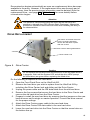
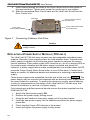
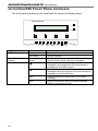
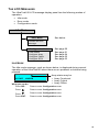
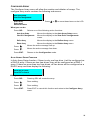
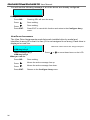
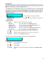
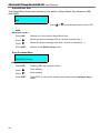
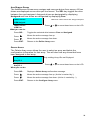
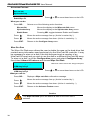
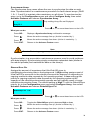
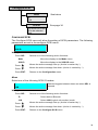
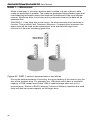
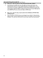
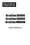
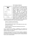
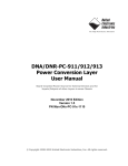
ULTRATRAK100 TX4
AND
ULTRATRAK100 TX8
USER MANUAL
COPYRIGHT
© 2001, Promise Technology, Inc.
Copyright by Promise Technology, Inc. (Promise Technology). No part of this
manual may be reproduced or transmitted in any form without the expressed,
written permission of Promise Technology.
TRADEMARKS
Promise, and the Promise logo are registered in U.S. Patent and Trademark
Office.
All other product names mentioned herein may be trademarks or registered
trademarks of their respective companies.
IMPORTANT DATA PROTECTION INFORMATION
You should back up all data before installing any drive controller or storage
peripheral. Promise Technology is not responsible for any loss of data resulting
from the use, disuse or misuse of this or any other Promise Technology product.
NOTICE
Although Promise Technology has attempted to ensure the accuracy of the
content of this manual, it is possible that this document may contain technical
inaccuracies, typographical, or other errors. Promise Technology assumes no
liability for any error in this publication, and for damages, whether direct, indirect,
incidental, consequential or otherwise, that may result from such error, including,
but not limited to loss of data or profits.
Promise Technology provides this publication “as is” without warranty of any kind,
either express or implied, including, but not limited to implied warranties of
merchantability or fitness for a particular purpose.
The published information in the manual is subject to change without notice.
Promise Technology reserves the right to make changes in the product design,
layout, and driver revisions without notification to its users.
RADIO FREQUENCY INTERFERENCE STATEMENT
This equipment has been tested and found to comply with the limits for a Class B
digital device, pursuant to Part 15 of the FCC Rules. These limits are designed to
provide reasonable protection against harmful interference in a residential
installation. This equipment generates, uses and can radiate radio frequency
energy, and, if not installed and used in accordance with the instruction may
cause harmful interference to radio communications. However, there is no
guarantee that interference will not occur in a particular installation. If this
equipment does cause harmful interference to radio or television reception, which
can be determined by turning the equipment off and on, the user is encouraged to
try to correct the interference by one or more of the following measures:
-
Reorient or relocate the receiving antenna.
-
Increase the separation between the equipment and receiver.
-
Connect the equipment into an outlet on a circuit different from that to which
the receiver is connected.
-
Consult Promise Technology, Inc. or an experienced radio/TV technician for
help.
This device complies with Part 5 of the FCC Rules. Operation is subject to the
following conditions: (1) This device may not cause harmful interference, and (2)
this device must accept any interference received, including interference that may
cause undesired operation.
NOTE: Only digital device equipment CERTIFIED CLASS B should be attached to
this equipment and that must have shielded cables.
TABLE OF CONTENTS
Introduction .................................................................................................................. 1
Architectural Description......................................................................................... 1
Features and Benefits ............................................................................................ 2
Getting Started ............................................................................................................. 3
Unpack UltraTrak100.............................................................................................. 3
Install Hard Drives .................................................................................................. 3
Connecting the SCSI Cables.................................................................................. 5
SCSI Cable Connection and Termination ............................................................ 5
Daisy Chaining Multiple Arrays............................................................................ 6
Daisy Chaining with Other SCSI Devices ............................................................ 6
Connect Power Cable and Switch Power On ......................................................... 7
Main Power Switch .............................................................................................. 7
Assign a SCSI ID.................................................................................................... 7
Configure the UltraTrak100 .................................................................................... 8
How to Automatically Create an Array ................................................................. 8
How to Manually Create an Array ........................................................................ 8
Gigabyte Boundary.............................................................................................. 9
Choosing Stripe Block Size ............................................................................... 10
Choosing a RAID Level ..................................................................................... 10
Partition and Format the Array ............................................................................. 12
Maintenance............................................................................................................... 13
Drive Status Indicators ......................................................................................... 13
Meaning of Status Indicators ............................................................................. 13
Critical & Offline Arrays ........................................................................................ 13
Rebuilding/Synchronizing Fault Tolerant Arrays................................................... 14
When a Disk Drive Fails ....................................................................................... 14
Replacing a Disk Drive Module ............................................................................ 14
Drive Replacement ............................................................................................... 15
Replacing a Power Supply Module (TX8 only) ..................................................... 16
UltraTrak100 Front Panel Interface ............................................................................ 18
The LCD Messages.............................................................................................. 19
Idle Mode........................................................................................................... 19
Configuration Menu ........................................................................................... 20
View Status Menu.............................................................................................. 21
Configure Array ................................................................................................. 24
Configure Array ................................................................................................. 25
Configure Cache................................................................................................ 32
Configure SCSI.................................................................................................. 33
Contacting Promise Support ...................................................................................... 35
Technical Support Services.................................................................................. 35
Limited Warranty ........................................................................................................ 37
Disclaimer of Other Warranties ............................................................................ 37
Returning Product For Repair (USA & Canada)......................................................... 39
Your Responsibilities ............................................................................................ 40
Appendix A - Technology Background ....................................................................... 41
Introduction to RAID ............................................................................................. 41
RAID 0 – Striping.................................................................................................. 41
RAID 1 – Mirroring................................................................................................ 42
RAID 0+1 – Striping/Mirror ................................................................................... 43
RAID 3 – Block Striping with Parity Drive ............................................................. 44
RAID 5 – Block and Parity Striping ....................................................................... 45
JBOD (Spanning) ................................................................................................. 46
Appendix B - Frequently Asked Questions................................................................. 47
INTRODUCTION
Thank you for purchasing Promise Technology’s UltraTrak100 TX4 or
UltraTrak100 TX8 external disk array system.
UltraTrak100 provides data storage solutions for applications where fault tolerance
and data redundancy are required. The failure of any single drive will not affect
data integrity or accessibility of the data. A defective drive may be replaced
without interruption of data availability to the host computer. A hot spare drive will
automatically replace a failed drive, securing the fault tolerant integrity of the
array. The self-contained hardware-based array provides maximum performance
in a compact external chassis.
The UltraTrak100 TX4 is an external disk array with an expandable capacity of up
to four individual disk drives. The UltraTrak100 TX8 is an external disk array with
an expandable capacity of up to eight individual disk drives.
The standard LVD SCSI interface provides compatibility with any system that
utilizes a SCSI interface. No vendor unique commands are required for the
operation of the disk array. Data transfer rates of up to 80 MB/sec are supported
via the SCSI interface.
ARCHITECTURAL DESCRIPTION
The UltraTrak100 disk array consists of either four (TX4) or eight (TX8) disk drive
bays, an enclosure with back plane, and the array controller. Multiple fans provide
redundancy to ensure continued usage during component failure. The array
controller is hardware based and controls all array functions transparently to the
host system. It appears to the system as a standard SCSI drive, and therefore
does not require any special software drivers.
Attention
The electronic components within the UltraTrak100 disk array are
sensitive to damage from ESD (Electro-Static Discharge). Appropriate
precautions should be observed at all times when handling the array or
its subassemblies.
1
UltraTrak100 TX4 and UltraTrak100 TX8 User Manual
FEATURES AND BENEFITS
Feature
Maximum fault tolerance
Supports RAID levels 0, 1, 3, 5,
0+1, and JBOD
Emulates standard SCSI-3 drive
to host
Supports asynchronous and
synchronous transfer mode
Tagged command queuing up to
32 commands
Front panel LCD and LED
indicators
Hot swap feature
Hot-spare drive
Automatic background data
reconstruction when a drive is
replaced
Redundant fans
Redundant Power Supply
(TX8 only)
2
Benefit
Ensures uninterrupted data availability
Allows system to be tuned for maximum performance
Compatible with all SCSI-3 or SCSI-2/LVD host adapters.
No special operating system drivers used
Up to 80MB/sec data transfer rates on the SCSI Bus
Maximum performance in Multi-Threaded Operating
Systems
Easy setup and quick response to problems, ensuring
maximum up time and manageability
Allows a defective drive to be replaced without
interrupting data accessibility to the host system
Maintains full fault tolerant integrity by automatically
rebuilding the data from a failed drive to an installed hot
spare drive
Array is quickly back on-line with minimal user
intervention
Load sharing and full operation even with a failed fan
Load sharing and uninterrupted operation with failure of
one power supply
GETTING STARTED
Caution
To prevent serious damage to the UltraTrak100 be sure that the voltageselect switch on the back of the power supply is set to your local voltage
(see Figure 2 on page 5).
Getting started with the UltraTrak100 consist of the following steps:
1.
2.
3.
4.
5.
6.
7.
Unpack UltraTrak100 storage subsystem (page 3).
Install Hard Drives (page 3)
Connecting the SCSI Cables (page 5).
Connect Power Cable and Switch Power On (page 7).
Assign a SCSI ID (page 7).
Configure the UltraTrak100 (page 8).
Partition and Format the Array (page 12).
UNPACK ULTRATRAK100
Open the UltraTrak100 box and carefully remove the UltraTrak100 unit and
accessories from the box. Be sure to remove the packing foam from within the
UltraTrak100 door. The UltraTrak100 and accessories include the following items:
•
•
•
•
UltraTrak100 unit
UltraTrak100 User Manual
Two drive-carrier keys
Terminator
• External LVD SCSI cable
• Power cord
• Screw sets for hard drives
Caution
The front panel door of the UltraTrak100 has foam inside it to prevent
damage during shipping. Remove this packing foam and retain for future
use.
INSTALL HARD DRIVES
Before using, the UltraTrak100 must first be populated with IDE hard drives. The
UltraTrak100 can support up to four hard drives in any of the configurations listed
below.
RAID
Configuration
RAID 0
RAID 1
RAID 3
RAID 5
RAID 0+1
JBOD (Spanning)
Number of Hard Drives
Minimum
Max (TX4)
Max (TX8)
2
4
8
2
4
8
3
4
8
3
4
8
4
4
8
1
4
8
You may mix manufacturer type and drive size – however, best performance is
achieved when you populate the array with identical models.
3
UltraTrak100 TX4 and UltraTrak100 TX8 User Manual
Before installing a new hard drive, be sure the jumpers on the new hard drives are
set for single or master operation. Consult the drive manual for the proper
settings.
Install new hard drives into the UltraTrak100 by doing the following:
1.
2.
3.
4.
5.
6.
7.
8.
Open the Front Panel Door on the UltraTrak100.
Unlock the Drive Carrier Latching Mechanism and remove an unused Drive
Carrier (see Figure 1 on page 4) from the UltraTrak100. (Begin at the top
and work down.)
Attach the Drive Carrier power cable to the hard drive (see Figure 7 on page
16).
Attach the Drive Carrier IDE data cable to the hard drive (see Figure 7 on
page 16).
Lower the hard drive into the Drive Carrier so that the screw holes on the
bottom line up.
Insert screws through the holes in the Drive Carrier and into the bottom of
the hard drive. Tighten each screw; be careful not to over tighten (see Figure
6 on page 15).
Slide the assembled Drive Carrier back into the UltraTrak100 and lock the
Drive Carrier lock.
Repeat steps 2 through 8 until all of the new hard drives are installed.
Drive Carrier Lock
Front Panel Door
Drive Carrier Latching Mechanism
Drive Carrier Assembly
Pulled part way out
Hinges out toward Front Panel Door
Figure 1. UltraTrak100 Disk Drive Access (TX4 Shown)
Note
The Drive Carrier Latching Mechanism must be locked or the disk drive
will not power up.
4
CONNECTING THE SCSI CABLES
Installation of the UltraTrak100 disk array is very similar to the installation of a
standard SCSI drive. The SCSI connector accepts the standard 68-pin LVD SCSI
connector used on most LVD SCSI devices. Refer to your system and/or SCSI
host adapter manual for additional installation procedures that may apply to your
system or host adapter.
SCSI-IN
SCSI Connector Input
COM-1
SCSI-OUT
/TERM
SCSI Connector
Output/Terminator
Power Switch
I
O
115
Voltage Select Switch
Figure 2. Back of UltraTrak100 TX4 (see Figure 8 for TX8)
Caution
To prevent possible damage to the array or system, ensure that system
power is OFF before connecting the cables.
SCSI CABLE CONNECTION AND TERMINATION
Two 68-pin wide SCSI connectors are provided on the back of the enclosure for
connecting the array to the system. These connectors are used in one of two
ways:
•
If the UltraTrak100 disk array is the only external SCSI device, or is the last
external device in a daisy-chained configuration, connect the incoming cable
5
UltraTrak100 TX4 and UltraTrak100 TX8 User Manual
(the one which is attached to the SCSI adapter) to the top connector, and
place an LVD SCSI active terminator on the other connector. An LVD SCSI
active terminator is included with UltraTrak100 disk array unit.
• If the array is to be placed in the middle of a daisy-chained configuration,
connect the incoming cable (the one which is attached to the SCSI adapter)
to the top connector and connect the outgoing cable (the one which
continues on to other devices) to the other connector. In this case, no
terminator is required at the array, but the last device in the daisy chain must
be terminated.
Correct SCSI termination procedures require that the first and last devices on the
SCSI bus be terminated. If the first or last device is not terminated, or if devices
other than the first and last are terminated, erratic SCSI bus performance will
occur. Typically, the system or host adapter is the first device and is already
terminated. When installing the UltraTrak100 disk array on a SCSI bus with other
devices, make sure the above rules are observed with all devices on the SCSI
bus. Consult your system and/or host adapter manual for additional information on
correct termination procedure.
Caution
Improper system operation will occur if the SCSI termination is incorrect.
Active termination and SCSI-3 compliant cables must be used. A SCSI-3
compliant cable is included with the UltraTrak100.
DAISY CHAINING MULTIPLE ARRAYS
Use a standard 68-pin SCSI-3 cable assembly to attach the array to the SCSI
chain. Attach each cable to the individual units to be connected on the SCSI bus.
Ensure that each device has a unique SCSI ID and that only the first and last
devices are terminated.
Terminator
Computer or
Workstation
UltraTrak100 TX4
UltraTrak100 TX4
UltraTrak100 TX4
Figure 3. Daisy Chaining Several UltraTrak100s Together
DAISY CHAINING WITH OTHER SCSI DEVICES
This procedure is essentially the same as the procedure outlined above for
multiple arrays. Refer to the manual associated with the other device or devices
for additional information that may be pertinent to that unit. Ensure that each
6
device has a unique SCSI ID and that only the first and last devices are
terminated. (See SCSI Cable Connection and Termination on page 5).
Terminator
SCSI ID
WIDE SCSI
COM2
Another SCSI
Device
Computer or
Workstation
UltraTrak100 TX4
UltraTrak100 TX4
Figure 4. Daisy Chaining UltraTrak100 with Other SCSI Devices
CONNECT POWER CABLE AND SWITCH POWER ON
The UltraTrak100 TX4 disk array includes a single power supply; The
UltraTrak100 TX8 includes two replaceable power supply modules. Both systems
will operate on either 115 volts AC or 230 volts AC. Ensure that the switch on the
back of each power supply is set to your local voltage. (See Figure 2 for the TX4;
see Figure 8 for the TX8.)
Caution
To prevent serious damage to the UltraTrak100 be sure that the voltageselect switch on the back of the power supply is set to your local voltage.
M AIN POWER SWITCH
The power switch is located on the back of cabinet. Switch the UltraTrak100
power on by pressing the portion of this switch marked “I”. Switch the power off by
pressing the portion of this switch marked “O”.
ASSIGN A SCSI ID
Each device on a SCSI chain must have a unique ID. Do the following to assign
the SCSI ID:
1.
From the Idle mode display, enter the Configuration menu by pressing the
SEL button. (See page 20 for more details.)
2.
At the Configuration menu, use the
button to select Configure SCSI,
and then press the SEL button. (See page 33 for more details.)
3.
At the Configure SCSI menu, use the
button to select the SCSI ID, and
then press the SEL button. (See page 34 for more details.)
4.
At the SCSI ID menu, use the
and
button to select the SCSI ID
number, and then press the SEL button. (See page 34 for more details.)
Press the EXIT button until you return to the Idle mode. (See page 19 for
more details.)
5.
7
UltraTrak100 TX4 and UltraTrak100 TX8 User Manual
CONFIGURE THE ULTRATRAK100
The configuration procedures for both the UltraTrak100 TX4 and UltraTrak100
TX8 are exactly the same. The following procedures provide the basic steps
needed to create an array and get your UltraTrak100 running quickly. Before
beginning, you need to decide if you will create an array using the automatic setup
features or if you will create the array manually. Both procedures are provided, but
you can only use one of them.
You may want UltraTrak100 to create the array for you if you do not have a good
technical understanding of various RAID technologies.
HOW TO AUTOMATICALLY CREATE AN ARRAY
1.
2.
3.
4.
Ensure that the UltraTrak100 power is off.
Install the disk drives into the UltraTrak100 and lock the Drive Carrier lever.
Switch the power on and wait for the UltraTrak100 to initialize.
Press the SEL button on the front panel.
5.
6.
Press
button once to select Configure Array, then press SEL.
Array Setup should be selected, press SEL.
If the message “*No Free Disk” appears, it means that an array has already
been configured. If you wish to re-create a new array, then you need to first
delete array before you can proceed. (See page 29, “Delete Array”, for more
details.)
With RAID Level selected, press SEL.
7.
and
button to select the proper RAID level for your array,
Use the
press SEL to choose the selected RAID level. See Choosing a RAID Level
on page 10 for help in choosing the proper RAID level.
9. Press SEL to create the array or press EXIT to cancel.
10. If you elected to create the array then you should see the message “Array
has been created.”
11. Switch the UltraTrak100 power off – wait 30 seconds and switch the power
back on.
You have successfully created an array automatically. If haven’t already done so,
you need to select a SCSI ID before you can begin using the UltraTrak100.
8.
HOW TO MANUALLY CREATE AN ARRAY
1.
2.
3.
4.
8
Ensure that the UltraTrak100 power is off.
Install the disk drives into the UltraTrak100 and lock Drive Carrier lever.
Switch the power on and about one minute for the UltraTrak100 to initialize.
Press the SEL button on the front panel.
5.
Press
6.
7.
Press
button twice to select Define Array, then press SEL.
With RAID Level selected, press SEL.
8.
Use the
and
button to select the proper RAID level for your array,
press SEL to choose the selected RAID level. See Choosing a RAID Level
on page 10 for help in choosing the proper RAID level.
button once to select Configure Array, then press SEL.
Note
If you wish to make a RAID 0+1 array using 4, 6, or 8 drives you need to
choose RAID 1 (mirroring) and then follow the steps below to create the
array.
9.
Press SEL to assign Stripe Block Size. 64KB is the optimum value for most
applications. Choosing the proper Stripe Block Size facilitates efficient data
flow. You might want to choose a different value if you know the size of the
cache buffer in your hard drives or the average data block size of the data
you retrieve. See Choosing Stripe Block Size on page 10 for more
information.
button to choose the GB Boundary feature. Press SEL to toggle
10. Press
between GB Boundary ON and GB Boundary OFF. The size of the array is
always restricted by the size of the lowest capacity disk drive. GB Boundary
ON (recommended) causes the size of the array to be rounded down to the
nearest whole gigabyte. GB Boundary OFF does not round off the size of
the array. (For example: Enabled—1.6GB = 1GB; Disabled—1.6GB =
1.6GB.) See Gigabyte Boundary below for more information.
Note
The Gigabyte Boundary feature is only available for RAID levels 1, 0+1,
3, and 5.
11. Press
button to choose the Add/Remove Drives feature then press SEL.
12. Use the
and
button to select each drive. Press SEL to toggle between
adding or removing a drive. Press EXIT when done.
13. Press SEL to Save Changes
14. Press SEL to create the array or press EXIT to cancel.
15. If you pressed SEL to create the array then you should see the message
“Array has been created.”
16. Switch the UltraTrak100 power off – wait 5 seconds and switch the power
back on.
You have successfully created an array manually. If haven’t already done so, you
need to select a SCSI ID before you can begin using the UltraTrak100.
GIGABYTE BOUNDARY
The Gigabyte Boundary feature is designed for fault tolerant arrays (RAID 1, 0+1,
3 and 5) in which a drive has failed and the user cannot replace the drive with the
same capacity or larger. Instead, the Gigabyte Boundary feature permits the
installation of a replacement drive that is slightly smaller (within 1 gigabyte) than
the remaining working drive (for example, a 20.5 GB drive would be rounded down
to 20 GB). This can be helpful in the event that a drive fails and an exact
replacement model is no longer available. Without this feature enabled,
UltraTrak100 will NOT permit the use of a replacement drive that is slightly smaller
than the remaining working drive.
9
UltraTrak100 TX4 and UltraTrak100 TX8 User Manual
For the Gigabyte Boundary feature to work, the Gigabyte Boundary feature must
be set to ON when the original array is created. When enabled, the Gigabyte
Boundary feature rounds the drive capacity of all drives to the common whole GB
drive size. For example, with the Gigabyte Boundary feature enabled, the
remaining working drives can be 20.5 GB and the replacement drive can be 20.3,
since all are rounded down to 20GB. This permits the smaller drive to be used.
Please note that users will lose a small amount of available storage capacity from
each drives in order to arrive at a common drive size.
CHOOSING STRIPE BLOCK SIZE
There are two issues to consider when selecting the Stripe Block Size.
First, you should choose a Stripe Block Size equal-to or smaller than the smallest
cache buffer found on any array disk drive. Selecting a larger value slows the
array down because disk drives with smaller cache buffers need more time for
multiple accesses to fill their buffers.
Secondly, if your data retrieval consists of fixed data blocks, such as with some
database or video applications – then you should choose that size as your Stripe
Block Size.
CHOOSING A RAID LEVEL
There are several issues to consider when choosing the RAID Level for your
UltraTrak100 array. Appendix A - Technology Background on page 41 gives
some technical insight regarding each RAID choice and the following discussion
summarizes some advantages, disadvantages and applications for each choice.
RAID 0
Advantages
Implements a striped disk array, the data is
broken down into blocks and each block is
written to a separate disk drive
I/O performance is greatly improved by
spreading the I/O load across many
channels and drives
Disadvantages
Not a "True" RAID because it is not faulttolerant
The failure of just one drive will result in all
data in an array being lost
Should not be used in mission critical
environments
No parity calculation overhead is involved
Recommended Applications for RAID 0
•
•
•
Image Editing
Pre-Press Applications
Any application requiring high bandwidth
RAID 1
Advantages
Simplest RAID storage subsystem design
Can increase read performance by
processing data requests in parallel since
the same data resides on two different
drives
10
Disadvantages
High disk overhead - uses only 50% of
total capacity
Recommended Applications for RAID 1
•
•
•
•
Accounting
Payroll
Financial
Any application requiring very high availability
RAID 3
Advantages
High Read data transfer rate
Disk failure has an insignificant impact on
throughput
Disadvantages
Parity drive can become bottleneck if a lot
of writes are occurring
Recommended Applications for RAID 3
•
•
•
Image Editing
Prepress Applications
Any application requiring high throughput
RAID 5
Characteristics/Advantages
High Read data transaction rate
Medium Write data transaction rate
Disadvantages
Disk failure has a medium impact on
throughput
Good aggregate transfer rate
Recommended Applications for RAID 5
•
•
•
•
File and Application servers
WWW, E-mail, and News servers
Intranet servers
Most versatile RAID level
RAID 0+1
Characteristics/Advantages
Implemented as a mirrored array whose
segments are RAID 0 arrays
Disadvantages
High disk overhead - uses only 50% of
total capacity
High I/O rates are achieved thanks to
multiple stripe segments
Recommended Applications for RAID 0+1
•
•
•
Imaging applications
Database servers
General fileserver
11
UltraTrak100 TX4 and UltraTrak100 TX8 User Manual
JBOD
Characteristics/Advantages
Uses 100% capacity of all hard drives
Disadvantages
The failure of just one drive will result in all
data in an array being lost
Should not be used in mission critical
environments
Recommended Applications for JBOD
•
•
File archiving
General fileserver
HOT SPARE DRIVE(S)
A good precaution to protecting your array integrity in the event of drive failure is
maintaining a hot spare drive. A hot spare is a drive that is connected to the array
system, but is not assigned as a member of the array. In the event of the failure of
a drive within a functioning fault tolerant array, the hot spare is activated as a
member of the array. The spare drive effectively takes the place of the failed drive
and the RAID system immediately begins to rebuild data on the drive. When the
rebuild is complete, the array is returned to fault tolerant status. Once the failed
drive is replaced, the new drive is automatically recognized as a hot spare in the
event of a subsequent drive fault.
PARTITION AND FORMAT THE ARRAY
Like any other type of fixed disk media in your system, a RAID array must also be
partitioned and formatted before use. Use the same method of partitioning and
formatting on an array as you would any other fixed disk.
Depending on the operating system you use, there may or may not be various
capacity limitations applicable for the different types of partitions.
12
MAINTENANCE
DRIVE STATUS INDICATORS
As shown in the figure below, each drive has three status LEDs.
Figure 5. Location of Drive Status Indicators (TX4 shown)
MEANING OF STATUS INDICATORS
Indicator
Power
Status
Disk
Color
Off
Green
Green
Amber
Red
Off
Green
Meaning
No disk drive power – power off or no disk installed.
Disk power on.
Normal
Data is being rebuilt to this drive
Failed
No drive installed or the drive has failed
This will blink on and off to indicate disk activity
CRITICAL & OFFLINE ARRAYS
A fault tolerant array goes "critical" when a drive is removed or fails. Due to the
fault tolerance of the array, the data is still available and online. However, once
the array goes critical, the array has lost its fault tolerance, and performance may
be adversely affected. If the fault was caused by a drive that was removed, the
drive should be replaced by another drive, either identical or larger, in order for the
RAID system to rebuild and restore optimal configuration.
13
UltraTrak100 TX4 and UltraTrak100 TX8 User Manual
A non-fault tolerant array goes "offline" when a drive is removed or fails. Since the
array is not fault tolerant, the data stored in the array is no longer accessible. If the
drive was removed, then it should be replaced to restore accessibility to the array.
If the drive failed, then the entire array must be deleted and re-initialized since all
data is considered lost.
REBUILDING/SYNCHRONIZING FAULT TOLERANT ARRAYS
Though a critical array can continue storage operations, it no longer offers fault
tolerance and should be addressed as soon as possible by replacing the missing
or failed drive(s).
Rebuild takes a replacement drive, assigns it to the array, and then writes the
redundancy data to it. Once the rebuild process is complete, the array status is
upgraded from “critical” to “functional” and fault tolerance is restored.
Synchronization is a preventative maintenance measure used to avoid problems
with data integrity. Synchronizing simply recalculates redundant data (similar to
the rebuild process) and matches the data on the drive(s).
To synchronize the array, go to the Configuration menu and select Configure
Array; then select Advance Features and choose Synchronize Array.
WHEN A DISK DRIVE FAILS
The UltraTrak100 provides both audible and visual indicators alerting you of a
drive failure. The following occur when a disk drive fails or goes offline:
•
•
•
•
•
Continuously produces short beeps every two seconds when a drive fails.
Continuously produces long beeps every 15 seconds when a drive is offline.
The Array LED on the front panel is yellow.
The disk drive Status LED (inside front panel door) is red.
The LCD displays a status message about the failure.
REPLACING A DISK DRIVE MODULE
UltraTrak100 disk drive modules should not be removed unless it has been
determined that a drive in the array has failed.
Generally, a disk drive that is a member of a fault tolerant array may be replaced
at any time without affecting the availability of data to the system. Depending on
the RAID type, drive removed, and type of access, performance may be reduced
until the drive is replaced.
Disk drives may be replaced while UltraTrak100 is running; special circuitry is
designed into the UltraTrak100 that protects the components and notifies the
processor.
Only a failed drive should be removed from the array. Removing any other drive
may cause the array to become unavailable. The replacement drive must be of
equal capacity or larger than the failed drive.
In arrays where a hot spare is already installed, the hot spare automatically
replaces the failed drive. When the failed drive is replaced, the new drive becomes
the new hot spare.
14
Reconstruction begins automatically as soon as a replacement drive becomes
available to the array. However, if the replacement drive was formerly part of
another array, then the previous array information must be deleted (from the
replacement drive – see page 29, “Delete Array”, for more details) before
reconstruction begins.
Attention
The electronic components within the UltraTrak100 disk array are
sensitive to damage from ESD (Electro-Static Discharge). Appropriate
precautions should be observed at all times when handling the array or
its subassemblies.
DRIVE REPLACEMENT
The bottom of the disk drive sets
into the mounting assembly.
Secure the disk drive in place
with four screws.
Drive Carrier Latching Mechanism
4 screws
Drive Carrier Lock
Figure 6. Drive Carrier
Caution
Do not replace the bad drive while reconstruction of the hot spare drive is
in progress. Wait until the System LED and all the drive LEDs (except
the failed drive) are green before replacing the failed drive.
Do the following to replace an IDE hard drive:
1.
2.
3.
4.
5.
6.
7.
8.
Open the Front Panel Door on the UltraTrak100.
Remove the hard drive you wish to replace from the UltraTrak100 by
unlocking the Drive Carrier lock and sliding out the Drive Carrier.
Unplug the power cable and the IDE data cable from the old hard drive.
Remove the four screws that secure the hard drive to the Drive Carrier and
remove the old hard drive from the Drive Carrier.
Prepare to install the new hard drive by ensuring that the jumpers on the new
hard drive are set for single or master operation. Consult the drive manual
for the proper settings.
Attach the Drive Carrier power cable to the new hard drive.
Attach the Drive Carrier IDE data cable to the new hard drive.
Lower the new hard drive into the Drive Carrier so that the screw holes on
the bottom line up.
15
UltraTrak100 TX4 and UltraTrak100 TX8 User Manual
9.
Insert screws through the holes in the Drive Carrier and into the bottom of
the new hard drive. Tighten each screw; be careful not to over tighten.
10. Slide the assembled Drive Carrier back into the UltraTrak100 and lock the
Drive Carrier lock.
Disk Drive
Connect Power Cable to
the Disk Drive
Connect Drive Data Cable
to the Disk Drive
Drive Carrier
Latching Mechanism
Figure 7. Connecting Cables to Disk Drive
Caution
Only qualified service personnel should remove and replace a power
supply module.
REPLACING A POWER SUPPLY MODULE (TX8 ONLY)
The UltraTrak100 TX8 disk array contains two hot-swappable redundant power
supplies. Normally, these supplies share the load between them. However each
power supply is capable of providing the power needed to maintain the array’s
normal operation. Each power supply LED should be on. An off or blinking LED on
the power supply indicates that the power supply has failed and should be
replaced. A power supply failure is also accompanied by an audible alarm (NOTE:
press the Power Supply Alarm Reset button to turn off the alarm). Contact your
dealer or reseller for additional details and assistance in obtaining a replacement
supply.
These power supplies are accessible from the rear of the unit (see Figure 8). The
power supply may be removed and replaced with an identical power supply while
the array remains in operation. To protect the electronic circuits, special sensing
circuitry is incorporated into the design of the UltraTrak100 TX8 disk array that
detects the insertion or removal of a power supply.
Only trained and qualified personnel should remove the power supplies from the
UltraTrak100 TX8.
1.
2.
3.
4.
5.
6.
16
Switch the failed power supply Off.
Remove the power supply locking screw.
Using the pull handle on the power supply pull it from the chassis.
Insert the new power supply into the chassis and switch the power supply
power On.
Check that the Power LED indicator is illuminated.
Insert and tighten the power supply locking screw.
Caution
Risk of electrical shock. When either power supply module is removed
from the chassis, AC power is accessible at the circuitry in the power
supply chassis. Only trained and qualified personnel should remove the
power supplies.
SC S I-IN
SCSI C onnector Input
C OM -1
SC S I-OU T
/TER M
SCSI C onnector
Output/Term inator
P o w e r S u p p ly M o d u le 1
O
I
115
Power Supply Switch
I
O
Power Switch
O
I
P o w e r S u p p ly M o d u le 2
Power Supply
Alarm R eset
115
Power Select Switch
Figure 8. Back of UltraTrak100 TX8
17
UltraTrak100 TX4 and UltraTrak100 TX8 User Manual
ULTRATRAK100 FRONT PANEL INTERFACE
The front panel interface for the UltraTrak100 consist of following items:
UltraTrak100 TX4
ARRAY
SCSI BUS
SEL
Type of Interface
LED Indicators
Liquid Crystal
Display
Control Buttons
Name
Array
SCSI Bus
Message Display
Panel
SEL
EXIT
18
EXIT
Comments
Activity Indicator
Activity Indicator
This is a 24-character by 2-row LCD that displays
various setup, status, and error messages.
Pressing this button scrolls any available
messages up through the LCD and activates a
message for the Select button.
Pressing this button scrolls any available
messages down through the LCD and activates a
message for the Select button.
Pressing this button selects the LCD’s active
message.
Pressing this button exits the active message
display to the previous level.
THE LCD MESSAGES
The UltraTrak100 LCD message display panel has the following modes of
operation:
•
•
•
Idle mode
Error mode
Configuration mode
Idle Mode
Error Mode
See below
Provides an error
message
Configuration Mode
See page 20
View Status
Configure Array
Configure Cache
Configure SCSI
See page 21
See page 24
See page 32
See page 33
IDLE MODE
The Idle mode message, such as shown below, is displayed during normal
operation of the UltraTrak100 when there are no problems or buttons being
pressed:
Array Functional
30°C/86°F
4500RPM
Array status may be:
! Array Functional
! Array Critical
! Array Offline
What you can do:
Press SEL:
Press to enter Configuration menu.
Press
:
Press to enter Configuration menu.
Press
:
Press to enter Configuration menu.
Press EXIT:
Press to enter Configuration menu.
19
UltraTrak100 TX4 and UltraTrak100 TX8 User Manual
The first line of the Idle mode menu will display one of the following status
messages:
• Array Functional
The array is fully operational, and no problems are
present.
• Array Critical
The array is operational, but has lost its fault tolerance.
For RAID array levels 1, 3 and, 5 the array contains a
failed drive. The user should identify and replace the
failed drive.
• Array Offline
The array is no longer operational. The array must be
rebuilt from the last tape backup or other device. For
RAID levels 1, 3, and 5, at least two or more drives in
the array have failed. For a RAID 0 array, at least one
drive has failed. The user should identify and replace
the failed drives.
The second line of the Idle mode menu can also provides the following error
information:
• Fan Error
Fan speed is <2000RPM or >5500RPM
• Array Rebuilding xx%
At least one array is rebuilding
• Array Synchronizing xx%
At least one array doing synchronize
CONFIGURATION MENU
In Configuration mode you may view the status of the UltraTrak100 system and
configure both UltraTrak100 hardware and arrays. The main configuration menu
allows the user to select the following menus:
View Status
Configure Array
Configure Cache
Configure SCSI
What you can do:
Press SEL:
Press
to move these items on the LCD.
Selects one of the following active functions:
View Status
Moves the display to the View Status menu.
Configure Array
Moves the display to the Configure Array menu.
Configure Cache
Moves the display to the Configure Cache menu.
Configure SCSI
Moves the display to the Configure SCSI menu.
Press
:
Moves the active message line up. (Active is marked by *.)
Press
:
Moves the active message line down. (Active is marked by *.)
Press EXIT:
20
or
Returns to the Idle mode.
View Status
View Controller Info
See page 22
Memory Size
Hardware Rev
Firmware Rev
View Cache Stats
See page 22
Cache Memory Size
Cache Block Size
Cache Read Hit
Cache Write Hit
View Array Information
See page 23
Array x Size
RAID x Status
View Enclosure
See page 23
Temperature
Fan 1 Status
Fan 2 Status
Fan 3 Status
Fan 4 Status
VIEW STATUS MENU
The View Status menu allows the user to select the information he wishes to view
with the following menu:
View Controller Info.
View Cache Stats
View Array Information
View Enclosure
What you can do:
Press SEL:
Press
or
to move these items on the LCD.
Selects one of the following active functions:
View Controller Info.
Moves the display to the View Controller Info menu.
View Cache Stats
Moves the display to the View Cache Stats menu.
View Array Information
Moves the display to the View Array Information menu.
View Enclosure
Moves the display to the View Enclosure menu.
Press
:
Moves the active message line up. (Active is marked by *.)
Press
:
Moves the active message line down. (Active is marked by *.)
Press EXIT:
Returns to the Configuration mode.
21
UltraTrak100 TX4 and UltraTrak100 TX8 User Manual
VIEW CONTROLLER INFORMATION
The View Controller Information mode displays UltraTrak100 firmware revision,
memory size, and hardware revision:
Memory Size: 16 MB
Where the values shown are simply examples.
Hardware Rev: PDC20265
Firmware Rev: V1.00 B00
Press
or
to move these items on the LCD.
What you can do:
Press SEL:
Does nothing.
Press
:
Moves the active message line up.
Press
:
Moves the active message line down.
Press EXIT:
Returns to the Configuration mode.
VIEW CACHE STATS
The View Cache Stats mode displays the cache memory size, cache block size,
the cache read hit percentage rate and the cache write hit percentage rate.
Cache Mem Size: 7 MB
Where the values shown are simply examples.
Cache Blk Size: 16 KB
Cache Read Hit : 10%
Cache Write Hit : 15%
What you can do:
or
Press SEL:
Does nothing.
Press
:
Moves the active message line up.
Press
:
Moves the active message line down.
Press EXIT:
22
Press
Returns to the Configuration mode.
to move these items on the LCD.
VIEW ARRAY INFORMATION
The View Array Information mode displays the array ID, array size, RAID level and
array status (Functional, Critical, Offline, Rebuilding and Synchronizing). If these
modes of display require more than 2 lines to display information the up and down
keys will be used to scroll the display.
The Array ID may be 1, 2, 3, or 4
Array: 0 Size: 12GB
Where the values shown are simply examples.
RAID 0 Functional
RAID 0
RAID 1
RAID 3
RAID 5
RAID 0+1
What you can do:
Functional
Critical
Rebuilding x%
Offline
Synchronizing x%
Array is Functioning properly
The array is in a degraded mode
Array is rebuilding – x% done
Array is down
Array is synchronizing – x% done
Press SEL:
Does nothing.
Press
:
Moves the active message line up.
Press
:
Moves the active message line down.
Press EXIT:
Returns to the View Status mode.
VIEW ENCLOSURE
The View Enclosure menu displays the following information:
Temperature: 30°C/86°F
FAN 1
Where the values shown are simply examples.
: 5009 RPM
FAN 2
: 4782 RPM
FAN 3
: 4896 RPM
FAN 4
: 4983 RPM
What you can do:
Press SEL:
Press
or
Does nothing.
Press
:
Moves the active message line up.
Press
:
Moves the active message line down.
Press EXIT:
to move these items on the LCD.
Returns to the Configuration mode.
23
UltraTrak100 TX4 and UltraTrak100 TX8 User Manual
C o nfig u re Array
Auto Array S etup
See page 25
Create/Cancel
V iew D rive Assignm ents
See page 26
Provides a list of
installed disk drives.
See page 27
D efine Array
RAID Level
Stripe Block Size
GB Boundary
Add/Rem ove Drives
Save Changes
D elete Array
See page 29
Provides a list of
assigned arrays.
Advanced Features
W ipeout Disk
Synchronize Array
Disable Buzzer
Rebuild/Sync Pri.
Provides a list of
installed disk drives.
Provides a list of
assigned arrays.
See page 30
See page 31
24
CONFIGURE ARRAY
The Configure Array menu will allow the creation and deletion of arrays. The
configure array menu contains the following sub menus:
Auto Array Setup
View Drive Assignments
Define Array
Delete Array
Advanced Feature
What you can do:
Press SEL:
Press
or
to move these items on the LCD.
Selects one of the following active functions:
Auto Array Setup
Moves the display to the Auto Array Setup menu.
View Drive Assignments
Moves the display to the View Drive Assignments
menu.
Define Array
Moves the display to the Define Array menu.
Delete Array
Moves the display to the Delete Array menu.
Press
:
Moves the active message line up.
Press
:
Moves the active message line down.
Press EXIT:
Returns to the Configuration mode.
AUTO ARRAY SETUP FUNCTION
In Auto Array Setup function, if there is only one free drive, it will be configured as
a RAID 0 array. If there are two free drives, they will be configured as a RAID 1
array. If there are more than two free drives, all free drives will be configured as a
RAID 5 array and then display the following:
Press SEL to Create
Press EXIT to Cancel
What you can do:
Press SEL:
Pressing SEL will create the array.
Press
:
Does nothing.
Press
:
Does nothing.
Press EXIT:
Press EXIT to cancel this function and return to the Configure Array
menu.
25
UltraTrak100 TX4 and UltraTrak100 TX8 User Manual
You will see the following message if all of the drives are already configured:
No Free Disk
What you can do:
Press SEL:
Pressing SEL will save the array.
Press
:
Does nothing.
Press
:
Does nothing.
Press EXIT:
Press EXIT to cancel this function and return to the Configure Array
menu.
VIEW DRIVE ASSIGNMENTS
The View Drive Assignments mode lists each installed drive by model and
identifies its array ID or that it is free (if it is not assigned to an array). Each drive is
displayed on one line.
1 MAXTOR Asng In Ary 1
Where the values shown are simply examples.
2 IBM Asng In Ary 2
3 MAXTOR Asng In Ary 3
4 IBM Asng In Ary 4
What you can do:
or
Press SEL:
Does nothing.
Press
:
Moves the active message line up.
Press
:
Moves the active message line down.
Press EXIT:
26
Press
to move these items on the LCD.
Returns to the Configure Array menu.
DEFINE ARRAY
The Define Array menu defines array parameters for the selected array. An array
number is selected by using the up/down key to select the array number field. The
SEL key is then used to select array number 1-4.
The parameter to be configured, RAID Level or Stripe Block size, is then selected
with up/down keys. Once the parameter is selected, the value is selected with the
up/down keys and then set by hitting the SEL key. If the Exit key is hit instead of
the SEL key the parameter value is not modified and the user may then select a
different parameter.
RAID Level
Stripe Block Size
"
GB Boundary ON
Add/Remove Drives
Save Changes
What you can do:
Press SEL:
This feature is not available in RAID 1.
Press
or
to move these items on the LCD.
Selects one of the following active functions:
RAID Level
Moves the display to the RAID Level menu.
Stripe Block Size
Moves the display to the Stripe Block Size menu.
GB Boundary ON
Toggles between ON and OFF.
Add/Remove Drives
Moves the display to the Add/Remove Drives menu.
Save Changes
Moves the display to the Save Changes menu.
Press
:
Moves the active message line up. (Active is marked by *.)
Press
:
Moves the active message line down. (Active is marked by *.)
Press EXIT:
Returns to the Configure Array menu.
You will see the following message if the array is already defined:
No Free Disk
What you can do:
Press SEL:
Pressing SEL will save the array.
Press
:
Does nothing.
Press
:
Does nothing.
Press EXIT:
Press EXIT to cancel this function and return to the Configure Array
menu.
27
UltraTrak100 TX4 and UltraTrak100 TX8 User Manual
STRIPE BLOCK SIZE
The Stripe Block Size menu allows you to select a Stripe Block Size between 4KB
and 64KB:
4KB
8KB
16KB
Press
or
to move these items on the LCD.
…
64KB
What you can do:
Press SEL:
Selects one of the active Stripe Block Size:
Press
:
Moves the active message line up. (Active is marked by *.)
Press
:
Moves the active message line down. (Active is marked by *.)
Press EXIT:
Returns to the Define Array menu.
SAVE CHANGES MENU
Press SEL to Create
Press EXIT to Cancel
What you can do:
Press SEL:
Press
:
Does nothing.
Press
:
Does nothing.
Press EXIT:
28
Pressing SEL will create the array.
Press EXIT to cancel this function and return to the Configure Array
menu.
ADD/REMOVE DRIVES
The Add/Remove Drives menu assigns and removes drives from arrays. All free
drives are displayed as one drive per line format. The SEL key toggles the drive
between free and assigned. Assigned drives are designated by displaying
Assigned and free drives are designated by displaying Free.
1 MAXTOR Free
Where the values shown are simply examples.
2 IBM Assigned
3 MAXTOR Free
4 IBM Free
What you can do:
Press SEL:
Press
or
Toggles the selected drive between Free and Assigned.
Press
:
Moves the active message line up.
Press
:
Moves the active message line down.
Press EXIT:
to move these items on the LCD.
Returns to the Define Array menu.
DELETE ARRAY
The Delete Array menu allows the user to select an array and delete the
configuration information for that array. This will also free any drives that have
been assigned to that array.
Array ID: 1
Only existing Array IDs are Displayed.
Array ID: 2
Array ID: 3
Array ID: 4
What you can do:
Press SEL:
Press
or
to move these items on the LCD.
Displays a Delete Array confirmation message.
Press
:
Moves the active message line up. (Active is marked by *.)
Press
:
Moves the active message line down. (Active is marked by *.)
Press EXIT:
Returns to the Configure Array menu.
29
UltraTrak100 TX4 and UltraTrak100 TX8 User Manual
ADVANCED FEATURE
Wipe out disk
Synchronize Array
Disable Buzzer
Rebuild/Sync Pri.
What you can do:
Press SEL:
Press
or
to move these items on the LCD.
Selects one of the following active functions:
Wipe out disk
Moves the display to the Wipe out disk menu.
Synchronize Array
Moves the display to the Synchronize Array menu.
Disable Buzzer
Pressing SEL toggles between Enable and Disable
Press
:
Moves the active message line up. (Active is marked by *.)
Press
:
Moves the active message line down. (Active is marked by *.)
Press EXIT:
Returns to the Configure Array menu.
WIPE OUT DISK
The Wipe Out Disk menu allows the user to delete the area on the hard drive that
contains array information used exclusively by the UltraTrak100 controller. It may
be necessary to wipe out a disk if the disk was previously a member of an
UltraTrak100 array and you wish to use the disk in a different UltraTrak100 array.
To wipe out a disk, go to the Configuration menu and select Configure Array;
then select Advance Features and choose Wipe Out Disk.
1 MAXTOR Asng In Ary 1
Where the values shown are simply examples.
2 IBM Asng In Ary 2
3 MAXTOR Asng In Ary 3
4 IBM Asng In Ary 4
What you can do:
Press SEL:
Press
or
to move these items on the LCD.
Displays a Wipe out disk confirmation message.
Press
:
Moves the active message line up. (Active is marked by *.)
Press
:
Moves the active message line down. (Active is marked by *.)
Press EXIT:
Returns to the Advance Feature menu.
Caution
The Wipe Out Disk option will delete all data on the drive that is
selected.
30
SYNCHRONIZE ARRAY
The Synchronize Array menu allows the user to synchronize the data on each
drive. Synchronization is a maintenance procedure for fault tolerant arrays (RAID
1, 0+1, 3 and 5) to maintain data consistency on all drives. To synchronize the
array, go to the Configuration menu and select Configure Array; then select
Advance Features and choose Synchronize Array.
Array ID: 1
Only existing Array IDs are Displayed.
Array ID: 2
Press
or
to move these items on the LCD.
What you can do:
Press SEL:
Displays a Synchronize Array confirmation message.
Press
:
Moves the active message line up. (Active is marked by *.)
Press
:
Moves the active message line down. (Active is marked by *.)
Press EXIT:
Returns to the Advance Feature menu.
Note
Promise Technology suggests synchronizing an array once a month.
Synchronization is a preventative maintenance measure used to avoid problems
with data integrity. Synchronizing simply recalculates redundant data (similar to
the rebuild process) and matches the data on the drive(s).
REBUILD/SYNC PRI.
Assigns the amount of importance that UltraTrak100 gives to
rebuilding/synchronizing data in the background. A High setting assigns most of
UltraTrak100’s resources to the rebuild process at the expense of responding to
ongoing read/write data requests by the operating system. A Low setting gives
priority to ongoing read/write data requests by the operating system at the
expense of the rebuild/synchronization process and will typically result in longer
rebuild/synchronization times. The default setting is High. To set the Rebuild/Sync
priority, go to the Configuration menu and select Configure Array; then select
Advance Features and choose Rebuild/Sync Pri.
Rebuild/Sync Pri. Low
Press
or
to move these items on the LCD.
What you can do:
Press SEL:
Toggles the Rebuild/Sync priority between High or Low
Press
:
Moves the active message line up. (Active is marked by *.)
Press
:
Moves the active message line down. (Active is marked by *.)
Press EXIT:
Returns to the Advance Feature menu.
31
UltraTrak100 TX4 and UltraTrak100 TX8 User Manual
Configure Cache
Write Cache
See below
Write Back
Write Thru
CONFIGURE CACHE
The Configure Cache menu will allow the setting of cache parameters. The
following parameter is set in the Configure Cache menu:
Write Cache
What you can do:
Press SEL:
Write Cache
Selects one of the following active functions:
Moves the display to the Write Cache menu.
Press
:
Moves the active message line up. (Active is marked by *.)
Press
:
Moves the active message line down. (Active is marked by *.)
Press EXIT:
Returns to the Configuration menu.
WRITE CACHE
Setting the Write Cache to Write Back improves performance, because a write to
the high-speed cache is faster than to disk. Data normally written to disk is first
written into the UltraTrak100’s cache, allowing the system CPU to continue with
other tasks while the UltraTrak100 handles writing data from it’s cache to the
array. However, write-back cache data is lost with a system power outage or other
event where the data has not yet been saved to disk. Setting the Write Cache to
Write Thru forces UltraTrak100 to immediately save all writes to the drive.
Write Back
Write Thru
What you can do:
Press SEL:
Write Back
Write Thru
Select function and return to Configure Cache menu.
Select function and return to Configure Cache menu.
Press
:
Moves the active message line up. (Active is marked by *.)
Press
:
Moves the active message line down. (Active is marked by *.)
Press EXIT:
32
Selects one of the following active functions:
Returns to the Configuration menu.
Configure SCSI
See below
Mode
ID
LUN
SCSI ID
See page 34
List SCSI IDs 0 thru
15 to be selected
from.
CONFIGURE SCSI
The Configure SCSI menu will allow the setting of SCSI parameters. The following
parameters are set in the configure SCSI menu:
Mode
SCSI ID
What you can do:
Press SEL:
Selects one of the following active functions:
Mode
Move the display to the Mode menu.
SCSI ID
Move the display to the SCSI ID menu.
Press
:
Moves the active message line up. (Active is marked by *.)
Press
:
Moves the active message line down. (Active is marked by *.)
Press EXIT:
Returns to the Configuration menu.
MODE
Select one of the following SCSI ID modes:
ID
Selected
LUN
Selected toggles between these two when SEL is
pressed.
What you can do:
Press SEL:
ID
Selects one of the following active functions:
Select device ID mode.
LUN
Select LUN (logical unit number) mode.
Press
:
Moves the active message line up. (Active is marked by *.)
Press
:
Moves the active message line down. (Active is marked by *.)
Press EXIT:
Returns to the Configure SCSI menu.
33
UltraTrak100 TX4 and UltraTrak100 TX8 User Manual
When using ID mode, if you have multiple arrays within an UltraTrak100 unit, each
array will use a separate SCSI ID. When using LUN mode, each UltraTrak100 unit
will use a single SCSI ID, with the first array being LUN 0, the second array being
LUN1, etc. Enable Multiple LUN support in your SCSI adapter if you choose LUN
mode. In most cases it is preferable to use ID mode.
SCSI ID
Select a SCSI ID between 0 and 15:
0
1
Selected
2
…
15
What you can do:
Press SEL:
Press
or
to move these items on the LCD.
Selects one of the following active functions:
from a list of numbers
between 1 and 15.
Selects the SCSI ID – The word Selected appears next
to the selected ID.
Press
:
Moves the active message line up. (Active is marked by *.)
Press
:
Moves the active message line down. (Active is marked by *.)
Press EXIT:
Returns to the Configure SCSI menu.
Note
If you have multiple arrays and are using ID mode, be aware that each
array will use a SCSI ID. If, for example, you have created two separate
arrays and have selected SCSI ID 4, array 1 would have SCSI ID 4 and
array 2 would have SCSI ID 5.
34
CONTACTING PROMISE SUPPORT
Promise Technical Support provides several support options for Promise users to
access information and updates. We encourage you to use one of our electronic
services, which provide product information updates for the most efficient service
and support.
If you decide to contact us, please have the following information available:
•
•
•
Product model and serial number
A description of the problem / situation
System configuration information, including: motherboard and CPU type,
hard drive model(s), IDE/ATAPI drives & devices, and other controllers.
TECHNICAL SUPPORT SERVICES
Promise OnlineTM Web Site
http://www.promise.com
(technical documents, drivers, utilities, etc.)
USA Tech Support Center
E-mail Support
[email protected]
Fax Technical Support
(408) 452-9163
Attention: Technical Support
Phone Technical Support
(408) 452-1180
7:30-5:00pm M-F Pacific Standard Time
If you wish to write us for support:
Promise Technology, Inc.
Attn: Technical Support
1460 Koll Circle, Suite A
San Jose, CA 95112 USA
European Tech Support
E-mail Support
[email protected]
Fax Technical Support
+31 (0)40 256 94 63
Attention: Technical Support
Phone Technical Support
+31 (0)40 256 94 61
8:30-5:00pm The Netherlands Time
If you wish to write us for support:
Promise Technology Europe B.V.
Attn: Technical Support
1 European Business Centre, Unit 1.25
Luchthavenweg 81
5657 EA Eindhoven, The Netherlands
35
UltraTrak100 TX4 and UltraTrak100 TX8 User Manual
Pacific Rim Sales Office
E-mail Support
[email protected]
Fax Technical Support
+886 3 578 23 90
Attention: Technical Support
Phone Technical Support
+886 3 578 23 95
9:00-5:30pm Taiwan Time
If you wish to write us for support:
Promise Technology, Inc.
Attn: Technical Support
2F, No. 30, Industry E. Rd. IX,
Science-Based Industrial Park,
Hsin-Chu, Taiwan, R.O.C.
China Office
36
E-mail Support
[email protected]
Fax Technical Support
+86 (0) 10 6872 3940
Attention: Technical Support
Phone Technical Support
+86 (0) 10 6872 3942
9:00-6:00pm China Time
If you wish to write us for support:
Promise Technology China
Attn: Technical Support
Room 3217, No. 15, Bai Shi Qiao Road
Hai Dian District Beijing 100081
P.R. China
LIMITED WARRANTY
Promise Technology, Inc. (Promise Technology) warrants that for two (2) years
from the time of the delivery of the product to the original end user:
a.
the product will conform to Promise Technology’s specifications;
b.
the product will be free from defects in material and workmanship under
normal use and service.
This warranty:
a.
applies only to products which are new and in cartons on the date of
purchase;
b.
is not transferable;
c.
is valid only when accompanied by a copy of the original purchase
invoice.
This warranty shall not apply to defects resulting from:
a.
improper or inadequate maintenance, or unauthorized modification(s),
performed by the end user;
b.
operation outside the environmental specifications for the product;
c.
accident, misuse, negligence, misapplication, abuse, natural or personal
disaster, or maintenance by anyone other than a Promise Technology or
a Promise Technology-authorized service center.
DISCLAIMER OF OTHER WARRANTIES
This warranty covers only parts and labor, and excludes coverage on software
items as expressly set above.
Except as expressly set forth above, Promise Technology disclaims any
warranties, expressed or implied, by statute or otherwise, regarding the product,
including, without limitation, any warranties for fitness for any purpose, quality,
merchantability, non-infringement, or otherwise. Promise Technology makes no
warranty or representation concerning the suitability of any product for use with
any other item. You assume full responsibility for selecting products and for
ensuring that the products selected are compatible and appropriate for use with
other goods with which they will be used.
Promise Technology does not warrant that any product is free from errors or that it
will interface without problems with your computer system. It is your responsibility
to back up or otherwise save important data before installing any product and
continue to back up your important data regularly.
Promise Technology’s sole responsibility with respect to any product is to do one
of the following:
a.
replace the product with a conforming unit of the same or superior
product;
b.
repair the product;
c.
recover the product and refund the purchase price for the product.
Promise Technology shall not be liable for the cost of procuring substitute goods,
services, lost profits, unrealized savings, equipment damage, costs of recovering,
37
UltraTrak100 TX4 and UltraTrak100 TX8 User Manual
reprogramming, or reproducing of programs or data stored in or used with the
products, or for any other general, special, consequential, indirect, incidental, or
punitive damages, whether in contract, tort, or otherwise, notwithstanding the
failure of the essential purpose of the foregoing remedy and regardless of whether
Promise Technology has been advised of the possibility of such damages.
Promise Technology is not an insurer. If you desire insurance against such
damage, you must obtain insurance from another party.
38
RETURNING PRODUCT FOR REPAIR (USA & CANADA)
If you suspect a product is not working properly, or if you have any questions
about your product, contact our Technical Support Department through one of our
technical services. You may reach our Technical Support Department as follows:
• Call us at (408) 452-1180
• E-mail us at [email protected]
However, before contacting Technical Support we ask that you first visit our
Technical Support web page at http://support.promise.com for the latest product
information and updates.
Please provide the following information when contacting Technical Support:
• Product model and serial number (required);
• Return shipping address
• Daytime phone number
• Description of the problem
• Copy of the original purchase invoice
The technician will assist you in determining whether the product requires repair. If
the product needs repair, the Technical Support Department will issue an RMA
(Return Merchandise Authorization) number.
Return only the specific product covered by the warranty (do not ship cables,
manuals, diskettes, etc.), with a copy of your proof of purchase to:
PROMISE TECHNOLOGY, INC.
Customer Service Dept.
Attn.: RMA # __________
1460 Koll Circle
San Jose, CA 95112
You must follow the packaging guidelines for returning products:
• Use the original shipping carton and packaging
• Include a summary of the product’s problem(s)
• Write an attention line on the box with the RMA number
• Include a copy of proof of purchase
You are responsible for the cost of insurance and shipment of the product to
Promise Technology. Note that damage incurred due to improper transport or
packaging is not covered under the Limited Warranty.
When repairing returned product(s), Promise Technology may replace defective
parts with new or reconditioned parts, or replace the entire unit with a new or
reconditioned unit. In the event of a replacement, the replacement unit will be
under warranty for the remainder of the original warranty term from purchase date,
or 30 days, whichever is longer.
Promise Technology will pay for standard return shipping charges only. You will
be required to pay for any additional shipping options (such as express shipping).
39
UltraTrak100 TX4 and UltraTrak100 TX8 User Manual
YOUR RESPONSIBILITIES
You are responsible for determining whether the product is appropriate for your
use and will interface with your equipment without malfunction or damage. You
are also responsible for backing up your data before installing any product and for
regularly backing up your data after installing the product. Promise Technology is
not liable for any damage to equipment or data loss resulting from the use of any
product.
40
APPENDIX A - TECHNOLOGY BACKGROUND
INTRODUCTION TO RAID
RAID (Redundant Array of Independent Disks) allows multiple hard drives to be
combined together to form one large logical drive or “array.” As far as the
operating system is concerned, the array represents a single storage device, and
treats it as such. The RAID software and/or controller handles all of the individual
drives on its own. The benefits of a RAID can include: higher data transfer rates
for increased server performance, increased overall storage capacity for a single
drive designation (such as, C, D, E, etc.), data redundancy/fault tolerance for
ensuring continuous system operation in the event of a hard drive failure.
Different types of arrays use different organizational models and have varying
benefits. The following outline breaks down the properties for each type of RAID
array:
RAID 0 – STRIPING
When a disk array is striped, the read and write blocks of data are interleaved
between the sectors of multiple drives (see Figure A1). Performance is increased,
since the workload is balanced between drives (or "members") that form the array.
Identical drives are recommended for performance as well as data storage
efficiency. The disk array's data capacity is equal to the number of drive members
multiplied by the smallest array member's capacity.
For example, one 1GB and three 1.2GB drives will form a 4GB (4 x 1GB) disk
array instead of 4.6 GB. The stripe block size value can be set logically from 4KB,
8KB, 16KB, 32KB, and 64KB. This selection will directly affect performance.
Larger block sizes are better for random disk access (like email, POS, or web
servers), while smaller sizes are better for sequential access.
RAID 0 (Striping)
Figure A1. RAID 0 striping interleaves data across multiple drives
41
UltraTrak100 TX4 and UltraTrak100 TX8 User Manual
RAID 1 – MIRRORING
When a disk array is mirrored, identical data is written to a pair of drives, while
reads are performed in parallel. The reads are performed using elevator seek and
load balancing techniques where the workload is distributed in the most efficient
manner. Whichever drive is not busy and is positioned closer to the data will be
accessed first.
With RAID 1, if one drive fails or has errors, the other mirrored drive continues to
function. This is called Fault Tolerance. Moreover, if a spare drive is present, the
spare drive will be used as the replacement drive and data will begin to be
mirrored to it from the remaining good drive.
Figure A2. RAID 1 mirrors identical data to two drives
Due to the data redundancy of mirroring, the drive capacity of the array is only the
size of the smallest drive. For example, two 1GB drives which have a combined
capacity of 2GB instead would have 1GB of usable storage when set up in a
mirrored array. Similar to RAID 0 striping, if drives of different capacities are used,
there will also be unused capacity on the larger drive.
42
RAID 0+1 – STRIPING/MIRROR
Striping/mirroring combines both of the previous array types. It can increase
performance by reading and writing data in parallel while protecting data with
duplication. At least four drives are needed for RAID0+1 to be installed. With a
four-drive disk array, drive pairs are striped together with one pair mirroring the
first pair. The data capacity is similar to a standard mirroring array, with half of the
total storage capacity dedicated for redundancy. An added plus for using RAID
0+1 is that, in many situations, such an array offers double fault tolerance. Double
fault tolerance may allow your data array to continue to operate depending on
which two drives fail.
Figure A3. RAID 0+1 striping and mirroring of two drive pairs
43
UltraTrak100 TX4 and UltraTrak100 TX8 User Manual
RAID 3 – BLOCK STRIPING WITH PARITY DRIVE
RAID level 3 organizes data across the physical drives of the array, and stores
parity information on to a drive dedicated to this purpose. This organization allows
increased performance by accessing multiple drives simultaneously for each
operation, as well as fault tolerance by providing parity data. In the event of a hard
drive failure, data can be re-calculated by the RAID system based on the
remaining drive data and the parity information.
The adjustable block size of the RAID 3 array allows for performance tuning based
on the typical I/O request sizes for your system. The block size must be set at the
time it is created and cannot be adjusted dynamically. Generally, RAID Level 3
tends to exhibit lower random write performance due to the heavy workload going
to the dedicated parity drive for parity recalculation for each I/O.
The capacity of a RAID 3 array is the smallest drive size multiplied by the number
of drives less one. Hence, a RAID 3 array with (4) 1.0 GB hard drives will have a
capacity of 3.0GB. An array with (2) 1.2GB hard drives and (1) 1.0GB hard drive
will have a capacity of 2.0GB.
Figure A4. RAID 3 multiple drives stripe data w/ one dedicated parity drive
44
RAID 5 – BLOCK AND PARITY STRIPING
RAID 5 is similar to RAID 3 as described above except that the parity data is
rotated across the physical drives along with the block data. Having the parity data
striped across all the physical drives in this manner removes the random write
performance bottleneck of RAID 3. The total capacity of a RAID 5 array is
calculated the same as a RAID 3 array.
Figure A5. RAID 5 stripes all drives with data and parity information
45
UltraTrak100 TX4 and UltraTrak100 TX8 User Manual
JBOD (SPANNING)
In a Spanning array, the disk array capacity is equal to the sum of all drives, even
if the drives are of different capacities. Spanning stores data onto a drive until it is
completely filled then proceeds to store data on to the next drive in the array.
There are no performance or fault tolerance array features in this type of array.
When a disk member fails, the entire array is offline.
Figure A6: Spanning uses full capacity of drives
46
Appendix B - Frequently Asked Questions
This section lists frequently asked questions involving pre-installation, drive
issues, installation, and post-installation.
Q.
What kind of hard drives can I use for an UltraTrak100 array?
A.
You can use any Ultra ATA/100, Ultra ATA/33/66, or EIDE hard drive(s) to
create arrays on the UltraTrak100. You should use matching drives for
multiple-drive arrays to maximize capacity usage as well as performance.
Ultra ATA/100 drives are recommended for highest performance.
Q.
Can I add a drive to an UltraTrak100 RAID array via hot-swap and
dynamically adjust the array size/configuration?
A.
No. The UltraTrak100 does not support dynamically adjustable RAID
size/configurations.
Q.
Can I take a set of drives that make up an array created on one
UltraTrak100 and move it to another UltraTrak100?
A.
Yes. All UltraTrak100’s read the arrays the same way. Once the drives are all
connected, you must restart the system for it to recognize the newly-inserted
array configuration.
Q.
Can I take a drive used in an UltraTrak100 array and access it directly
with a different controller, such as the one integrated on the
motherboard?
A.
Yes, but only under certain configurations. The following array configurations
will allow the drive(s) to be accessed individually on another controller: mirror
(RAID 1), or single drive striped (RAID 0). Multiple drives striped will not
work.
Q.
How can I be sure that write-back cache has flushed before I reboot
after partitioning and formatting an array?
A.
A cache flush is always triggered immediately following any write from the int
13h BIOS. This level of array support is what FDISK and FORMAT use to
access the drive from MSDOS. With no delay in the write operation, there is
no cached data waiting to be written. If you are running from Windows
NT/2000 or other operating systems, as usual, make sure to shut down
Windows properly so that the operating system can trigger and flush the
cache as necessary. NOTE: powering off before a proper shutdown is
complete may result in the loss of unwritten data in the cache, possibly
causing problems in a subsequent boot or access to the data that was
unwritten.
47
UltraTrak100 TX4 and UltraTrak100 TX8 User Manual
48
Q.
Why can’t I see the drives on the UltraTrak100 under FDISK?
A.
If you have not created an array, the physical drive(s) attached to the
UltraTrak100 card will not be recognized by the operating system. The
UltraTrak100 controller is dedicated to RAID array management and does
not provide any means of addressing individual hard drives through the int
13h interface used by FDISK. In order to access drives on the UltraTrak100
from MSDOS at all, you must first create a RAID array.
Q.
Why can’t I see the array I just created in the Windows NT/2000 Disk
Administrator?
A.
Since Windows NT/2000 does not yet support any method of dynamically
adding and/or removing logical devices to/from the system, you must restart
Windows. The next boot will show the new array under Disk Administrator.