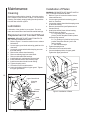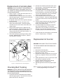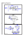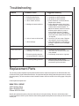
1
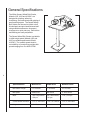
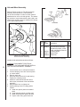
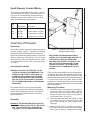
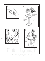
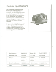
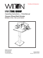
This Manual is Bookmarked Operating Instructions — Parts Manual Square Wheel Belt Grinder Models: 4103, 4106, and 4126AC WHM TOOL GROUP 2420 Vantage Drive Elgin, Illinois 60123 Ph.: 800-274-6848 www.wmhtoolgroup.com Part No. 5507796 Revision C2 09/04 Copyright © WMH Tool Group Table of Contents Cover Page .........................................................................................................................................1 General Specifications ......................................................................................................................... 4 Operating Precautions ......................................................................................................................... 5 Setup and Operation............................................................................................................................7 Maintenance ...................................................................................................................................... 10 Wiring Diagrams ................................................................................................................................ 12 Replacement Parts ............................................................................................................................ 13 Troubleshooting ................................................................................................................................. 13 Accessories ....................................................................................................................................... 17 3 General Specifications The Wilton Square Wheel Belt Grinder, Models 4103, 4106 and 4126AC, are designed for grinding, deburring, chamfering, and internal/external grinding of small and large parts. The Square Wheel Belt Grinder can be used to polish or buff finished parts and grind small internal radii using available accessories. Accessory changeover is quick and easy. Belt tension and tracking are easily adjustable. The Square Wheel Belt Grinder is available in either single speed (Models 4103 and 4106) or variable speed model (Model 4126AC). The variable speed model is controlled by an inverter that provides belt speeds ranging from 0 to 6000 SFPM. 4 Specifications Model 4103 Model 4106 Model 4126AC Belt Width & Length 2 x 72 Inches 2 x 72 Inches 2 x 72 inches Belt Speed 4600 SFPM 4600 SFPM 0 - 6000 SFPM Motor 1 HP, Single Phase, 1750 rpm 2 HP, Three Phase, 1750 rpm 1 HP, 1,750 rpm Contact Wheel Diameters 1-1/2, 3, & 8 inches 1-1/2, 3, & 8 inches 1-1/2, 3, & 8 inches Weight 115-125 pounds 120 pounds 120 pounds - Misuse of this machine can cause serious injury. - For safety, machine must be set up, used and serviced properly. - Read, understand and follow instructions in the operator’s and parts manual which was shipped with your machine. When setting up machine: - Always avoid using machine in damp or poorly lighted work areas. - Always be sure machine is securely anchored to the floor. - Always keep machine guards in place. - Always put start switch in OFF position before plugging in machine. When using machine: - Never operate with machine guards missing. - Always wear safety glasses with side shields (See ANSI Z87.1) - Never wear loose clothing or jewelry. - Never overreach you may slip and fall into the machine. - Never leave machine running while you are away from it. - Always shut off the machine when not in use. When servicing machine: - Always unplug machine from electrical power while servicing. - Always follow instructions in operators and parts manual when changing accessory tools or parts. - Never modify the machine without consulting Wilton Corporation. You — the stationary power tool user— hold the key to safety. Read and follow these simple rules for best results and full benefits from your machine. Used properly, Wilton’s machinery is among the best in design and safety. However, any machine used improperly can be rendered inefficient and unsafe. It is absolutely mandatory that those who use our products be properly trained in how to use them correctly. They should read and understand the Operators and Parts Manual as well as all labels affixed to the machine. Failure in following all of these warnings can cause serious injuries. Machinery general safety warnings 1. Always wear protective eye wear when operating machinery. Eye wear shall be impact resistant, protective safety glasses with side shields which comply with ANSI Z87.1 specifications. Use of eye wear which does not comply with ANSI Z87.1 specifications could result in severe injury from breakage of eye protection. 2. Wear proper apparel. No loose clothing or jewelry which can get caught in moving parts. Rubber soled footwear is recommended for best footing. 3. Do not overreach. Failure to maintain proper working position can cause you to fall into the machine or cause your clothing to get caught pulling you into the machine. 4. Keep guards in place and in proper working order. Do not operate the machine with guards removed. 5. Avoid dangerous working environments. Do not use stationary machine tools in wet or damp locations. Keep work areas clean and well lit. 6. Avoid accidental starts by being sure the start switch is OFF before plugging in the machine. 7. Never leave the machine running while unattended. Machine shall be shut off whenever it is not in operation. 8. Disconnect electrical power before servicing. Whenever changing accessories or general maintenance is done on the machine, electrical power to the machine must be disconnected before work is done. 9. Maintain all machine tools with care. Follow all maintenance instructions for lubricating and the changing of accessories. No attempt shall be made to modify or have makeshift repairs done to the machine. This not only voids the warranty but also renders the machine unsafe. 10. Machinery must be anchored to the floor. 11. Secure work. Use clamps or a vise to hold work, when practical. It is safer than using your hands and it frees both hands to operate the machine. 12. Never brush away chips while the machine is in operation. 13. Keep work area clean. Cluttered areas invite accidents. 14. Remove adjusting keys and wrenches before turning machine on. 15. Use the right tool. Don’t force a tool or attachment to do a job it was not designed for. 16. Use only recommended accessories and follow manufacturers instructions pertaining to them. 5 17. Keep hands in sight and clear of all moving parts and cutting surfaces. 18. All visitors should be kept at a safe distance from the work area. Make workshop completely General Electrical Cautions This machine should be grounded in accordance with the National Electrical Code and local codes and ordinances. This work should be done by a qualified electrician. The machine should be grounded to protect the user from electrical shock. safe by using padlocks, master switches, or by removing starter keys. 19. Know the tool you are using—its application, limitations, and potential hazards. Wire sizes Caution: for circuits which are far away from the electrical service box, the wire size must be increased in order to deliver ample voltage to the motor. To minimize power losses and to prevent motor overheating and burnout, the use of wire sizes for branch circuits or electrical extension cords according to the following table is recommended: Conductor Length AWG (American wire gauge) Number 240 Volt Lines 120 Volt Lines 0 - 50 Feet 50 - 100 Feet Over 100 Feet No. 14 No. 14 No. 14 No. 14 No. 12 No. 8 Safety requirements for abrasive grinding machines 6 Abrasive grinding can be hazardous to operators and bystanders. Grinding sparks, chips and dust particles thrown off by the grinding disc can cause serious injury by contact or inhalation. To avoid such injuries you must comply with the following safety requirements: 1. Always wear protective eyewear when operating machinery. Eye wear shall be impact resistant, protective safety glasses with side shields which comply with ANSI Z87.1. Use of eye wear which does not comply with ANSI Z87.1 specifications could result in severe injury from breakage of eye protection. See Figure A, below. 2. Wear leather safety gloves, arm guards, leather aprons and safety shoes. 3. A dust collection system is recommended, Operator shall also wear a dust mask at all times. See Figure B, below. 4. Additional precautions may be necessary for grinding materials which are flammable or have other hazardous properties. You should always consult the manufacturer of such materials for instructions on grinding and handling. 5. Do not force or jamb the workpiece into the grinding disc. 6. Before grinding, always allow the motor to come up to operating speed, then check the grinding disc for wobble, runout, or any unbalanced A B 7. 8. 9. 10. 11. 12. condition. If the disc is not operating accurately and smoothly, immediately stop the motor and make repairs before attempting any grinding operations. Abrasive discs must be stored in a controlled environment area. Relative humidity should be 35% to 50% and the temperature should be between 60 and 80 degrees Fahrenheit. Failure to do so could cause premature disc failure. Examine the face of the grinding disc carefully. Excessive grinding which wears down to the backing material can tear the disc. Never use a disc which shows backing, nicks or cuts on the surface or edge or damage due to creasing or poor handling. When installing a new disc, be certain the disc is accurately centered on the drive wheel. Failure to do so could cause a serious unbalanced condition. Always present the workpiece to the wheel while resting the workpiece firmly on the table. Failure to do so could result in damage to the workpiece or throwing of the workpiece off the wheel. Safety shoes which comply with ANSI Z41.1 shall be worn. See Figure C. Personal hearing protection such as ear plugs or ear muffs shall be used to protect against the effect of noise exposure. See Figure D: C D Introduction This manual includes operating and maintenance instructions for the Wilton Model 4103, 4106 and 4126AC Square Wheel Belt Grinder. The manual also includes parts listings and illustrations of replaceable parts. Refer to Figures 1 and 2 for key features of the Square Wheel Belt Grinder. Setup and Operation The Square Wheel Belt Grinder can be mounted on a work bench or an optional pedestal. The grinder should be secured to the work bench or pedestal using the four holes in the base of the grinder. (Refer to Assembly of Pedestal for machines that are to be pedestal-mounted.) Installation of Work Rest The work rest mounts on the left side of the head casting. Attach the work rest using the socket head cap screw provided with the machine. The slot in the work rest has a lip against which the cap screw is tightened. Place the hole at the end of the slot over the cap screw. Then slide the rest inward until the work rest is in position in front of the contact wheel. Tighten the cap screw. Belt Tension Lever Motor Belt Tracking Adjustment Upper Guard Inverter Belt Tracking Adjustment Upper Guard ON/OFF Switch Motor 7 Work Rest Switch Contact Wheel Work Rest Contact Wheel Pedestal Pedestal Figure 1: Square Wheel Grinder Features (single speed) Figure 2: Square Wheel Grinder Features (variable speed) Vacuum Connection Operating Controls NOTE: A variety of vacuum system options are available. (Refer to Accessories section.) Model 4103/4106 The ON/OFF switch for the Model 4103/4106 grinder is located in a switch box mounted on the drive motor. The grinder uses a front mounted vacuum system. Refer to Fgure 3. Install the vacuum system components as follows: 1. Slide the support bracket into the channel secured to belt grinder base. Install one knob in the belt grinder base to secure the support bracket. NOTE: Refer to vacuum scoop exploded view, Figure 11 when installing channel. 2. Slide the ducted scoop onto the support bracket. Install remaining knob in the support bracket to secure the scoop. 3. Connect hose to exhaust duct and secure with a clamp. Model 4126AC NOTE: Refer to Figure 4. Use only the inverter controls defined in the following procedures. The inverter is pre-programmed at the factory and requires no further programming.The controls for the Model 4126AC grinder are located on the inverter. The ON/OFF switch is located on the left side of the inverter. Start the grinder by setting the ON/OFF switch to ON. Press the FWD RUN pushbutton on the inverter and set the speed using the up/down arrow keys (to the right of the speed display). Press the up arrow to increase speed; press the down arrow to reduce speed. The display on the inverter shows drive motor speed in revolutions per minute. Press the STOP button on the inverter to stop the grinder. Then set the ON/OFF switch to OFF. STOP Button Up FWD (Forward) Button On/Off Switch Speed Display (RPM) 8 Clamping Knob Support Bracket Scoop Clamping Knob Figure 3: Vacuum Connection Electrical Connection Refer to the Wiring Diagram section for wiring information. Connection to electrical power should be made by a qualified electrician. Observe local electrical codes when connecting the machine. Figure 4: Operating Controls (Model 4126AC) Down Typical Uses for the Square Wheel Belt Grinder Flat or angular stock — Platen setting is the perfect angle for high speed, precision, flat and level grinding of tools, knives, plastics, and other materials. The platen allows working to very close tolerances. An adjustable work rest is standard on all models. Shaping — For grinding and finishing cylindrical shapes. The yoke surface conforms to the shape of the surface to produce an even, smooth finish without the danger of scarring. Excellent for tool post applications. Roughing — Serrated contact wheel is used for removing heavy stock, cleaning up a weld or snagging a casting. This durable 8-inch diameter wheel is used extensively for hollow grinding and profiling knives and other culinary tools. It is standard equipment on all models. Contouring — Grind difficult, hard to reach areas with the 3-inch by 2-inch or 11/2 inch by 2-inch diameter contact wheels. Contours and shapes unique parts like propellers and metal furniture. OPTIONAL FEATURES 9 Internal contouring — The air-cushioned dead head is for use on very small radius grinding. When connected to a source of shop air (80-90 psi), the belt rides on a cushion of air to decrease head and belt wear. The dead head is easy to use, and adapts to any of the available radius tips. Internal contouring with small wheel — This small wheel accessory is designed for hard to reach places. Includes 5/8-inch, 70 durometer contact wheel. Available contact wheels are 1/2-inch, 3/4inch, and 1-inch. Polishing — The buffing pad is perfect for satin finish or high gloss polishing. The fine, close stitched burring pads are ideal for metal and plastic Finishing — The nylon reinforced, silicone carbide wheel is perfect for polishing and deburring. It applies a high luster finish on rough surfaces and is excellent for steel, iron, or aluminum. Maintenance Installation of Platen Cleaning WARNING: BE SURE TO SET ON/OFF SWITCH OFF TO AVOID PERSONAL INJURY. 1. Refer to Figure 6. Lower the tension lever to release belt tension. 2. Loosen upper guard knob and swing guard back for clearance. 3. Loosen the contact wheel shaft clamping screw on the head casting. 4. Remove contact wheel (see Replacement of Contact Wheel). 5. Install pivot shaft of platen in head casting. Position platen as desired. A. For grinding flat or angular work pieces, position the platen with the platen surface facing outward. B. For grinding of cylindrical work pieces, position the platen with the “yoke” side facing outward. C. Set at desired angle. 6. Tighten clamping screw. 7. Lift tension lever to set belt tension. 8. Lower and adjust position of upper guard. Tighten the upper guard knob. Shutoff the machine before cleaning. Keep the exterior of the machine clean and free of chips. Use a brush for cleaning. Periodically empty grinding dust and particles from the dust collection system. Lubrication Lubrication of the grinder is not required. The drive motor and contact wheel are fitted with sealed bearings. Replacement of Contact Wheel WARNING: BE SURE TO SET ON/OFF SWITCH TO OFF TO AVOID PERSONAL INJURY. 1. Refer to Figure 5. Lower the tension lever to release belt tension. 2. Loosen upper guard knob and swing guard back for clearance. 3. Loosen the contact wheel shaft clamping screw on the head casting. 4. Remove the contact wheel assembly. 5. Remove retaining rings from wheel shaft. 6. Remove shaft and wheel bearings. 7. Install bearings in replacement contact wheel. 8. Install shaft and secure with retaining rings. 9. Install contact wheel shaft in head casting. 10. Tighten clamping screw. 11. Lift tension lever to set belt tension. 12. Lower and adjust position of upper guard. Tighten the upper guard knob. 10 Tension Lever Platen Clamping Screw Pivot Shaft Upper Guard Upper Guard Knob Clamping Screw Contact Wheel Head Casting Figure 5: Replacement of Contact Wheel Work Rest Figure 6: Installation of Platen Replacement of Grinding Belt WARNING: DO NOT OPERATE THE MACHINE WITH THE SIDE PANEL OPEN. DISCONNECT ELECTRICAL POWER TO THE MACHINE BEFORE PERFORMING ANY MAINTENANCE. 1. Refer to Figure 7. Lower the belt tension lever to release tension on the belt. 2. Loosen the knob on the left side of the machine and raise upper guard. Turn the knob on the side panel and lower the side panel. 3. If required, loosen work rest to provide clearance for belt removal. 4. Remove the belt from the drive wheel, idler wheel, and contact wheel. Install the replacement belt over the drive wheel, idler wheel, and contact wheel. 5. Raise the belt tension lever to tighten the belt against the wheels. Tighten the belt until it is just taut. A moderate tension will provide faster cutting, longer belt life, and better tracking. Do not over-tension the belt. 6. Check belt tracking by spinning the drive wheel by hand. Adjust tracking if required. (Refer to Checking Belt Tracking.) Idler Wheel Upper Guard Grinding Belt 2. Spin the drive wheel by hand and check tracking of the belt. If the belt tracks either right or left, adjustment is required. 3. Use an Allen wrench to change the alignment of the idler wheel. Turn the idler adjustment screw clockwise to cause the belt to track right. Turn the idler adjustment screw counterclockwise to cause the belt to track left. 4. Close side panel and secure by turning the knob on the panel. Lower the upper belt guard and secure with the knob on the left side of the grinder. 5. Connect electrical power and start the grinder. Check belt tracking (the belt should be centered on the contact wheel. 6. If required, adjust belt tracking to center the belt on the contact wheel. Turn the idler adjustment screw clockwise to move the belt to the right. Turn the idler adjustment screw counterclockwise to move the belt to the left. 7. If the belt does not track properly, increase belt tension. Repeat steps 1 through 6. Replacement of Inverter WARNING: DISCONNECT ELECTRICAL POWER TO THE MACHINE BEFORE PERFORMING ANY MAINTENANCE. Drive Wheel Contact Wheel Side Panel Figure 7: Replacement of Grinding Belt Checking Belt Tracking WARNING: DO NOT OPERATE THE MACHINE WITH THE SIDE PANEL OPEN. DISCONNECT ELECTRICAL POWER TO THE MACHINE BEFORE PERFORMING ANY MAINTENANCE. 1. Loosen the knob on the left side of the machine and raise upper guard. Turn the knob on the side panel and lower the side panel. 1. Disconnect electrical power. 2. Remove access panel on front of inverter. Disconnect inverter wiring. 3. Remove four screws (1) and four nuts (6) from inverter (2). Separate inverter (2) from mount (4). 4. Install replacement inverter (2) and secure with four screws (1) and four nuts (6). 5. Connect electrical wiring (refer to Wiring Diagram section for connections). 6. Start belt grinder and check for proper operation. NOTE: Inverter is pre-programmed at the factory, further programming is not required. 11 Wiring Diagrams Model 4103 12 Model 4106 Model 4126AC Troubleshooting Problem Probable Cause Suggested Remedy Poor Tracking 1. 2. 3. 4. 1. 2. 3. 4. Improper belt splice. Excessive belt tension. Insufficient belt tension. Worn contact surfaces. Check belt for irregular seam or shape. Set tension so belt is just taut. Set tension so belt is just taut. Check elastomer on contact wheels. Replace worn wheels. Check alignment of drive wheel and contact wheels. The drive pulley and contact wheel must be aligned. To adjust drive wheel, loosen set screws and move drive wheel in or out on motor shaft as required. To adjust contact wheel, loosen shaft clamping screw and move contact wheel in or out as required. Check for 1/16-inch crown. Replace drive wheel if crown is not present. Check all bearings for overheating or damage. Replace worn or damaged bearings. Set tension so belt is just taut. 5. Misaligned contact surfaces. 5. 6. Lack of crown on drive wheel. 6. 7. Worn bearings. 7. Slack Belt 1. Insufficient belt tension. 1. Contact Wheel Wear 1. Excessive belt tension. 2. Grinding in one area on belt. 1. Set tension so belt is just taut. 2. Use entire work surface of belt when ever possible. 3. Periodically clean interior of grinder. 3. Excessive grinding deposits on belt and debris in machine. Short Belt Life 1. Excessive grinding pressure. 1. Allow the belt to do the cutting. Excessive pressure dulls the belt and removes the grit from the belt. Replacement Parts This section provides exploded view illustrations that show the replacement parts for the Wilton Models 4103, 4106 and 4126AC Square Wheel Belt Grinder. Also provided are parts listings that show part number, description and quantity. The item numbers on the illustration relate to the item number in the facing page of the parts listing. Order replacement parts from: WMH TOOL GROUP 2420 Vantage Drive Elgin, Illinois 60123 Phone: 800-274-6848 Identify the replacement part by the part number shown in the parts listing. Be sure to include the model number and serial number of your machine when ordering replacement parts to assure that you will receive the correct part. 13 14 Exploded View - Square Wheel Belt Grinder 45 Parts List - Square Wheel Belt Grinder Ref. Part No. Number 1 9 10 11 5510944 5510943 5510942 5044590 5044610 9049821 5507582 9100331 9074011 9074081 5510946 5510947 5510948 5053231 9074381 9112811 12 13 14 15 16 17 18 19 20 21 22 23 24 25 26 27 28 29 5044400 5044410 5044370 9128441 5049990 9129881 9055361 9129861 5046571 9055381 9010271 5044651 9133041 5046560 9133191 9129561 9059811 5053301 2 3 3A 4 5 6 7 8 Description Contact Wheel Assy, 10 x 2 Serrat, 90 Duro Contact Wheel Assy, 8 x 2 Smooth, 50 Duro Contact Wheel Assy, 8 x 2 Serrated, 50 Duro Contact Wheel Assy, 1-1/2 x 2 Contact Wheel Assy, 3 x 2 Screw, Flat Head Cap Idler Wheel Bearing Retaining Ring, Internal Retaining Ring, External Contact Wheel, 8 x 2 Serrated, 50 Duro Contact Wheel, 8 x 2 Smooth, 50 Duro Contact Wheel, 10 x 2 Serrated, 90 Duro Shaft, 8 x 10 Wheel Retaining Ring, External Abrasive Belt, 2 x 72, 50 Grit (Standard optional grit below) (10 piece minimum order) Platen Casting Work Rest Casting Head Casting Screw, Socket Head Cap 3/8-16 x 1 Screw, Work Rest Machine Screw, Socket Head Cap 3/8-16 x 5/8 Flat Washer, Nylon 1/2 I.D. x 1 O.D. Scr, Socket Head Cap, Fll Thrd, 3/8-24 x 3 Bearing, Idler Housing Flat Washer, Nylon, 3/8 O-Ring, 1/2 Cap, Idler Housing Pin Set Screw, Socket Head 1/4-20 x 1/4 Lever, Tension Set Screw, Nylon Tipped 5/16-18 x 3/4 Locknut, Hex, 3/8-24 Roll Pin, 3/16 x 1-1/2 Shaft, Idler Pulley Ref. Part No. Number Qty. 30 1 1 1 1 1 2 1 2 2 2 1 1 1 1 1 31 5541241 5644231 9066821 32 33 34 35 36 37 38 39 40 41 42 43 44 45 46 47 48 49 9066831 5508076 9070361 9070781 9128671 9114320 5044511 9054541 5630451 5077041 9070381 5630061 5507583 5055311 9070371 5044630 9057461 5046600 5046540 5541030 1 1 1 1 1 1 2 1 1 1 2 1 1 1 1 1 1 1 1 Description Switch (Model 4103 only) Manual Motor Starter (Model 4106 only) Motor & Switch, 1 HP, Single Phase (Model 4103) Motor, 2 HP, 3 Phase (Model 4106) Motor, 1 HP, 3-Phase (Model 4126AC only) Knob, Hand Nut, Allen, 5/16-18 Bolt, Hex Head, w/Nylock 3/8-16 x 3/4 Key, 3/16 x 3/16 x 1-1/4 Pulley, Drive Set Screw, Socket Head 5/16-18 x 1/2 Screw, Socket Head Hex 5/16-18 x 1-1/2 Lock Washer, 5/16 Latch, Cam Nut, Hex, 5/16-18 Washer, Nylon 5/16 Door Knob, Hand Guard Flap Assembly Washer, Flat 0.26 x 0.63 x 0.06 Tracking Leader Assembly Casting, Idler Housing Main Frame Assembly Qty. 1 1 1 1 1 1 1 1 4 1 1 2 1 2 1 1 2 1 1 1 1 1 1 1 15 Parts List - Inverter Ref. Part No. Number Description 1 2 3 4 5 16 5550874 Screw, Socket head Cap, 10-32NF x 3/8 5507817 inverter (1ph, 120V, 50/60Hz) 5507818 Inverter (3ph, 220V, 50/60Hz) 5511447 Inverter (3ph, 440V, 50/60Hz) 9128571 Screw, Hex Head 1/2-13 x 1 5515215 Mount, Inverter 9119481 Terminal, Full Closed Qty. 7 1 1 1 1 Ref. Part No. Number Description 6 7 9 10 12 13 14 5508073 5507934 9119721 9117401 9085061 9119071 5628371 Nut, Lock, 10-32 Nylock Box, Switch Spade, Female 16-14AWG Switch, Toggle Dial, ON-OFF Grip, Cord Lock Washer, 1/2 Qty. 4 1 4 1 1 2 1 Accessories Belt Grinder Pedestal The optional pedestal enables the Square Wheel Belt Grinder to be mounted in a free standing configuration rather than on a work bench. The grinder is secured to the pedestal using the four holes in the base of the grinder (refer to page 22). Dust Collection Systems A dust collection system is available as an option (refer to page 24 for additional coverage). The dust collection system can be used in two configurations: as a machine base (Figure 9) or as a stand- alone system (Figure 8). Figure 8: Stand-Alone Dust Collection System In the stand-alone configuration, the dust collection system is placed next to the grinding machine, and the dust collection hose connected to the inlet duct. It may also be placed between two grinding machines, making use of the inlet ducts on both sides of the dust collection system. Another option is to use the dust collection system as a base for the Model 4103 grinding machine in lieu of placing the machine on a bench or on the pedestal. The second inlet duct on the side of the system is available for connecting another grinding machine. In areas with limited space, this may be the most desirable option. 17 The dust collection system features a chip drawer into which grinding debris is collected. The dust collection system has a filter at the rear to filter out remaining grinding debris. The system has a removable top that provides access for cleaning and maintenance. The system is controlled by an ON/OFF toggle switch on the motor at the rear of the machine. Figure 9: Dust Collection System Used as Grinder Base Exploded View - Vacuum Scoop A vacuum scoop connects the machine to the vacuum system. The mounting provisions for the scoop are shown in the exploded view below. 15 7 14 13 10 1 12 10 12 11 2 10 9 3 4 8 7 6 5 18 Ref. Part No. Number Description 1 2 3 4 5 6 7 5053531 Scoop Assembly 5052471 Adapter, Hose 5053601 Reducer, 4 x 3 in. (Woodworkers) 5053611 Reducer, 4 x 3 in. (Metal Workers) 5507534 Clamp, Hose 3 in. 5507533 Hose, 3 x 5 in. 9128241 Screw, HH Cap 9070361 Knob Qty. 1 1 1 1 1 1 3 2 Ref. Part No. Number Description 8 9 10 11 12 13 14 15 5053571 9032961 9055411 5053581 9057391 9056411 9062111 9146801 Rail Lock Nut, Nylon Insert Washer, Nylon Channel Washer, Flat Nut, Hex Jam Screw, SHCS (5/16-18 X 3/4) Screw, SHCS Low Head (5/16-18 X 1 1/2) Figure 11: Vacuum Scoop Exploded View Qty. 1 4 8 1 2 3 2 2 Air Cushioned Dead Head Assembly 8 Refer to Figures 10 and 11. The air-cushioned dead head is for use on very small radius grinding. When connected to a source of shop air (80-90 psi), the belt rides on a cushion of air to decrease head and belt wear. The dead head is easy to use, and adapts to any of the available radius tips. 1 Install the dead head assembly as follows: WARNING: DISCONNECT ELECTRICAL POWER TO THE MACHINE BEFORE INSTALLING THE DEAD HEAD ASSEMBLY. 1. Lower tension lever to release belt tension. 2. Loosen clamping screw and remove platen or contact wheel. 3. Insert the shaft of the dead head assembly in head casting. Position dead head assembly with the tip parallel with the machine base. Tighten the clamping screw. 4. Install the belt under the dead head contact wheel and over the dead head tip. 5. Lift the tension lever to tighten the belt. 6. Check belt tracking. 7. Connect pressurized air supply (80-90 psi). 8. Check operation of the dead head assembly. 6 7 4 5 3 Ref. Part No. Number Figure 10: Internal Contouring with Air Cushioned Dead Head 2 1 5044960 2 3 4 5044970 5044991 5045011 5045031 5045051 5045071 5 5044610 6 7 5045101 9062441 8 9049761 Description Air Cushion Dead Head Assembly (Note 1) Casting, Dead Head Tip, Dead Head, 3/16 R x 2 Tip, Dead Head, 1/4 R x 2 Tip, Dead Head, 5/16 R x 2 Tip, Dead Head, 3/8 R x 2 Fitting, Flareless Compression, 1/4 x 1/8 Contact Wheel Assembly 3x2 Spacer Screw, Socket Head Cap 10-32 x 1/2 Screw, Socket Head Flare Qty. 1 1 1 1 1 1 1 1 1 2 1 Note 1: Includes 3/8 R x 2 dead head tip 5045051. Other tips available at additional cost. Figure 11: Air Cushioned Dead Head Assembly Parts Breakdown 19 Hub and Wheel Assembly Refer to Figures 12 and 13. The hub and wheel assembly Small Diameter Contact Wheels can be used to adapt a number of other optional attachments for use on the belt grinder. The assembly consists of a pre-balanced hub shaft, collar, and V-belt and a special wrench to enable quick change of the optional attachments. V-Belt Collar Hub Shaft 1 Ref. Part No. Number Figure 12: Polishing with Hub and Wheel Assembly Install the hub and wheel assembly as follows: 20 WARNING: DISCONNECT ELECTRICAL POWER TO THE MACHINE BEFORE INSTALLING THE HUB AND WHEEL ASSEMBLY. 1. Lower tension lever to release belt tension. 2. Loosen clamping screw and remove platen or contact wheel. 3. Remove work rest. 3. Insert the shaft of the hub in head casting. Tighten the clamping screw. 4. Install the V-belt around the idler wheel, drive wheel, and wheel of hub and wheel assembly. 5. Raise tension lever to tighten belt. 6. Install polishing wheel or buffing pad as follows: A. Install one spacer plate on threaded shaft. B. Install polishing wheel or buffing pad. C. Install second spacer plate and collar. D. Tighten collar using special wrench. 1 5054920 2 3 4 5045141 5058071 5044620 4 Description Hub and Wheel Assembly (Includes Hub Shaft, V-Belt, Collar, and Special Wrench) Polishing Wheel Spacer Plate Buffer Pad Figure 13: Hub and Wheel Assembly Qty. 1 1 2 1 Small Diameter Contact Wheels Small diameter contact wheels are useful for grinding or contouring difficult, hard to reach areas (refer to Figure 15). The small diameter contact wheels are available in several sizes. Refer to Figure 14 for a listing of small diameter contact wheels. Dia. (In.) Part Number Description 1/2 5057871 Contact Wheel, 70 Duro 5/8 5057881 Contact Wheel, 70 Duro 3/4 5057891 Contact Wheel, 70 Duro 1 5057901 Contact Wheel, 70 Duro Figure 14: Small Diameter Contact Wheels. Assembly of Pedestal Unpacking The grinding machine pedestal is shipped separately from the grinding machine. Transport the shipping containers to the installation site before unpacking. Unpack the pedestal and grinding machine. Locate and open the plastic bag containing four 5/16-18 socket head cap screws. Verify that that there are two screws 1-inch long and two screws 1-3/4 inches long (Figure 16, View A). Securing the Pedestal WARNING: BOLTING THE PEDESTAL TO THE FLOOR IS STRONGLY RECOMMENDED. THE PEDESTAL IS BOLTED TO THE FLOOR TO ELIMINATE THE POSSIBILITY OF TIP-OVER WHILE THE MACHINE IS BEING OPERATED. FAILURE TO DO SO CAN RESULT IN INJURY TO THE OPERATOR AND/OR OTHER NEARBY PERSONNEL. The pedestal has four mounting holes in its base. Use these mounting holes to secure the pedestal to the floor before installing the grinder. Shims should be used to level the pedestal before the attaching bolts are tightened. Assembly WARNING: THE MACHINE MOUNTING PLATE IS NOT CENTERED ON THE LEG OF THE PEDESTAL. THIS OFFSET EVENLY DISTRIBUTES THE WEIGHT OF THE GRINDING MACHINE. Figure 15: Contouring Using Small Diameter Contact Wheel MAKE SURE THE GRINDING MACHINE IS CORRECTLY POSITIONED AND SECURED TO THE PEDESTAL BEFORE LEAVING THE MACHINE UNATTENDED. FAILURE TO CORRECTLY POSITION AND SECURE THE MACHINE COULD RESULT IN THE MACHINE TIPPING OVER, CAUSING INJURY TO PERSONNEL. There are four mounting holes in the mounting plate on the pedestal. The holes on the motor side of the machine are approximately 20 inches apart. The holes on the belt-guard side of the machine are located approximately ½-inch from the corners of the plate. When correctly installed, all four screw holes in the machine base plate and belt guard will align with the holes in the mounting plate of the pedestal. Mounting Procedure A. Using two people or a hoisting device, lift the grinding machine and set it on the pedestal. Align all four screw holes in the machine base plate and belt guard with the holes in the mounting plate of the pedestal (Figure 16, View B). B. Open the grinding belt guard door (Figure 16, View C). Install two 5/16-18 x 1-inch long screws in the base of the grinding belt guard. Install screws finger-tight. C. Install the two 5/16-18 x 1-3/4-inch long screws in the screw holes on the motor side of the machine base (Figure 16, View D). Tighten all four screws. 21 B A Belt Guard Holes Approximately 1/2-inch from corners 2 3 Motor Side Holes 20 inches apart C 1 D 3 Install two 1inch long screws 22 2 Ref. No. 1 2 3 Part Number 5248081 9062121 5511051 Install two 1 3/4-inch screws Description Pedestal Socket Head Cap Screw (5/16-18 x 1) Socket Head Cap Screw (5/16-18 x 1 3/4) Figure 16: Assembly of Grinding Machine and Pedestal Qty. 1 2 2 Dust Collection System (Optional) Installation Transport the shipping container to the installation site. Unpack the dust collection system and check for damage. Contact the carrier if damage is found. Open the installation kit (refer to Optional Accessories in the parts listing for installation kits). Install cover and debris collection drawer if removed. Slip a hose clamp over the 3-inch vacuum hose. Slip the hose on the inlet duct(s). Move the clamp over the duct to secure the hose. Filter Check for accumulation of debris. Replace the filter at intervals that you determine are appropriate for your shop environment and machine utilization. Drawer Seal Check the drawer seal periodically and replace if damaged or missing. Keep the seal in good condition to help maintain collection system efficiency. Repeat the procedure to connect the hose to the other duct on the grinding machine. Electrical Connection ON/OFF switch on motor at rear of dust collection system Removable cover – remove for interior cleaning/access to impeller Refer to the Dust Collection System Wiring Diagram for wiring information. Connection to electrical power should be made by a qualified electrician. Observe local electrical codes when connecting the machine. Second Inlet Duct on this side Operation The dust collection system motor is started by setting the toggle switch on the motor to the ON position. Set the switch to OFF to shut down the dust collection system. Maintenance 23 WARNING: · MAKE SURE YOU DISCONNECT ELECTRICAL POWER TO THE DUST COLLECTION SYSTEM BEFORE PERFORMING MAINTENANCE. FAILURE TO DO SO MAY RESULT INJURY TO THE OPERATOR AND/OR MAINTENANCE PERSONNEL. · DO NOT OPERATE THE DUST COLLECTION SYSTEM WITH THE COVER REMOVED. INJURY TO FINGERS AND HANDS FROM THE FAN BLADES, AND INGESTION OF LOOSE FITTING CLOTHING INTO THE AIR INLET WITH RESULTANT INJURY IS ALSO POSSIBLE. Cleaning Periodically dispose of accumulated chips and debris from the chip drawer. Use a brush to loosen debris from internal surfaces. Use a vacuum cleaner to clean up the loosened debris. Outlet filter at rear removes fine debris from outlet air stream Inlet Duct – Connect 3 inch hose - secure with clamp Chip Drawer Pull to Open Figure 17: Dust Collector Assembled View Disassembly Disassembly of the dust collection system is required only to replace the motor or the fan components. The motor switch, if failed, can be replaced without removal of the motor. 1. Remove chip drawer (2) and cover (4) from base (1). 2. Remove the filter cover (5) and filter (6). Replace filter if required. 3. Remove five nuts (10) and lock washers (11) from studs at rear of base (1). 4. Remove four nuts (12) and lock washers (13) from screws (14). Remove screws (14) from inside fan housings. Separate motor support panel (9) (with fan and motor still attached) from base (1). 5. Remove five nuts (17), lock washers (18) and screws (19) that secure the fan housings together. 6. Using a flat bladed tool, separate the outer fan housing (16) from the inner fan housing (24). 7. Using an Allen wrench, loosen set screw (22). Remove fan (21) from shaft of motor (25). Remove key (23) from motor shaft. 8. Use a flat-bladed screwdriver to hold flat head screws (28) (in inner fan housing). Remove four nuts (26) and lock washers (27) from the flat head screws (28) in motor mounting lugs. Assembly 24 Assembly is the reverse of disassembly. Observe the following during assembly: 1. Assemble motor (25) and inner fan housing (24) on rear panel; make sure fan duct is facing downward. 2. Make sure guard strap (20) is installed in the recesses in fan duct. 3. Mate fan housings (16 and 24). Turn fan (21) by hand to check for rubbing. Adjust fan as required. 4. Use a spare screw or a Phillips screwdriver to align screw holes in outer fan housing (16), spacer (15), and in the internal panel of base (1). 5. With the screw holes aligned, install the support panel (9) on the five studs at the rear of base (1). 6. Connect electrical power and check operation of the dust collection system. Exploded View – Model 5511885 Dust Collection System 15 14 16 21 22 26 24 28 27 19 20 12 9 23 13 18 28 27 17 11 25 10 5 44 6 25 REAR VIEW 7 8 11 2 2 FRONT VIEW 33 Parts List – Model 5511885 Dust Collection System Ref. No. 1 2 3 4 5 6 7 8 9 10 11 12 13 14 15 16 17 18 Part Number 5514731 5514732 5514733 5514734 5514735 5514779 5514736 5514737 5514738 5514739 5514740 5514741 5514742 5514743 5514744 5514745 5514746 5514747 Description Base Drawer, Chip Seal, Tape (5-feet long) Cover Cover, Filter Filter Panel, Rear Foam Panel, Side Foam Panel, Motor Support Nut, Hex Washer, Lock Nut, Hex Washer, Lock Screw, Hex Head Spacer Housing, Outer Fan Nut, Hex Washer, Lock Qty 1 1 1 1 1 2 1 5 5 4 4 4 1 1 5 5 Ref. No. 19 20 21 22 23 24 25 26 27 28 Part Number 5514748 5514749 5514750 5514751 5514752 5514753 5514754 5514755 5514756 5514757 Qty 5 1 1 1 1 1 1 4 1 1 Connection Kits: Refer to Wilton catalog for appropriate connection kit for your grinding machine or contact Wilton for assistance. Wiring Information - Dust Collection System 26 Description Screw, Hex Head Strap, Guard Fan Screw, Set Key Housing, Inner Fan Motor Screw, Hex Head Seal, Tape 5-feet long Switch, Motor 27 WMH TOOL GROUP 2420 Vantage Drive Elgin, Illinois 60123 Phone: 800-274-6848