1
Operator's Manual
4 x 36" Belt
SANDER
8" Disc
Model No.
351.21 5200
CAUTION:
Read and follow
all Safety Rules and Operating
Instructions before First Use
of this Product. Keep this
manual with tool.
Sears, Roebuck and Co., Hoffman Estates, IL 60179 U.S.A.
_II_W.
$ Ba rS.CO _cr
a_s
man
23738.01 Draft (06/16/05)
• Proper electrical receptaale should be available for tool.
Three-prong plug should be plugged directly into properly
grounded, three-prong receptacle.
Warranty .........................................
Safety Rules ......................................
2
2
Unpacking .......................................
Assembly ......................................
Installation ......................................
3
3-4
4-5
Operation ......................................
Maintenance .....................................
6-8
9
Troubleshooting ...................................
Parts [llustrationand List ........................
9
10-13
Espafiol ......................................
14-23
• Extension cords should have a groundingprong and me three
wires of the extension cord shouldbe of the correctgauge.
• Keep visitors at a safe distance from work area.
• Keep children out of workplace. Make workshop shildproof.
Use padlocks, master switches or remove switch keys to
prevent any unintentional use of power tools.
TOOL SHOULD BE MAINTAINED
• Always unplug tool prior to inspection.
• Consult manual for specific maintaining and adjusting
procedures.
• Keep tool lubricated and clean for safest operation.
• Remove adjusting tools. Form habit of checking to see that
adjusting tools are removed before switching machine on.
ONE-YEAR
FULL WARRANTY
ON CRAFTSMAN
TOOL
• Keep all parts in working order. Check to determine that the
guard or other parts will operate properly and perform their
intended function.
I_thLsCraftsman tool fails due to a defect in matedal or
workmanship within one year from the date of pumhase CALL
t-80O-4-MY-HOME® TO ARRANGE FOR FREE REPAIR.
• Check for damaged parts. Check for alignment of moving
parts, binding, breakage, mounting and any other condition
that may affect a tool's operation.
• A guard or other part that is damaged should be properly
repaired or replaced. Do not perform makeshift repairs.
(Usa parts list provided to order replacement parts.)
If this tool is used for commercial or rents1 purposes, this warranty will apply for only ninety days from the date of purchase.
This warranty applies only while this tool is in the United
States.
This warranty gives you specific legal rights and you may also
have other dghts, which vary, from state to state.
KNOW HOWTO
Sears, Roebuck and Co., Dept. 817WA, Hoffman Estates,
IL 60179
• Use right teal for job. Do not force tool or attachment to do
a job for which it was not designed.
• Disconnect tool when changing belt or abrasive disc.
• Avoid accidental start-up. Make sure that the tool is in the
"OFF" position before plugging in.
WARNING: For your own safety, read all af the instructions
and precautions before operating tool.
• Do not force tool. It will work most efficiently at the rate for
which it was designed.
CAUTION: Always follow proper operating procedures as
defined in this manual even if you are familiar with use of this
or similar tools. Remember that being careless for even a
fraction of a second can result in severe personal Injury.
BE PREPARED
• Keep hands away from moving parts and sanding surfaces.
• Never leave tool running unattanded.Tum the power off
and do not leave tool until it comes to a complete stop.
• Do not overreach. Keep proper footing and balance.
FOR JOB
• Never stand on tool. Serious injury could occur if tool is
tipped or ff belt or disc are unintentionatly contacted.
• Wear proper apparel, Do not wear loose clothing, gloves,
neckties, rings, bracelets or other jewelry which may get
caught in moving parts of machine.
• Know your tool Learn the tool's opera, on, application and
specific limitations.
• Wear protective hair c=Overingto contain long hair.
• Wear safety shoes with non-slip soles.
• Use recommended accessories (rarer to page 13). Use of
improper accessories may cause risk of injury to persons.
• Handle the workpiece correctly. Protect hands from possible injury.
• Wear safety glasses complying with United States ANSI
Z87.1. Everyday glasses have only impact resistant lenses.
They are NOT safety glasses.
• Turn machine off if it jams. Belt jams when it digs too
deeply into workpiecs. (Motor force keeps it stuck in the
• Wear face mask or dust mask if operation is dusty.
work.)
• Be alert and think clearly. Never operate power tools when
tired, intoxicated or when taking medications that cause
Support workpieee with miter gauge, belt platen or work
table.
drowsiness.
• Maintain '/_" maximum clearance between table and sanding belt or disc.
PREPARE WORK AREA FOR JOB
• Keep work area clean. Cluttered work areas (nvfteaco_denfs.
CAUTION: Think safety! Safety is a combination of operator
common sense and alertness at all times when tool is being
used.
• Do not use power tools in dangerous environments. Do not
use power tools in damp or wet locations. Do not expose
power tools to rain.
• Work area should be properly lighted.
© Sears, Roebuck and Co.
USE TOOL
WARNING: Do not attempt to operate tool until it is oomplete)y assembled according to the instructions.
2
•
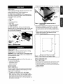
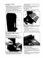
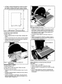
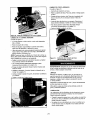
Press one foot onto each comer
of the base of the sander.
Refer to Figure 1,
Check for shipping damage. If damage has occurred, a claim
must be filled with carrier. Check for completeness,
Immediately report missing parts to dealer.
The sander comes assembled as one unit. Additional parts
which need to be fastened to sander, should be located and
accounted for before assembling.
A Sander
Mounting
Brackets
B Work Stop
C Table
D
E
F
G
Dust Collection Bag
Bag Clamp
Miter Gauge Assembly
Handle with Washer
Figure 2 - In_rl Mounting Brackets into Slots of
Sander Base
•
Not Shown: Abrasive Disc, Knob (2), Foot (4), Mounting
Bracket (4), M6 x 16 Socket Head Bolt (2). M6 x 16 Hex Head
Bolt (4), M6 Look Washer (2), M6 Flat Washer (6), M6 Hex
Nut (4). 3 and 5mm Hsx Wrench.
Sander
can be installed
(see Recommended
lock washers
ed).
•
A
on a workbench
Accessories,
and hex nuts and mounting
Figure 3 shows the base dimensions,
brackets
mounting
required space to allow for table assembly
assembly in horizontal position.
C
or a tool stand
page 13) usir_g bolts,
(includ-
holes and
and belt
-'It
7"
Figure 1 - Unpacking Sander
24"
Refer to Figures 2 - 6.
I_
CAUTION: Do not attempt assembly if parts are missing.
Use this manual to order replacement parts.
!2"
WARNING: Do not operate machine until completely assembled. Do not operate machine until you have completely read
and understood this manual.
TOOLS
18"
Figure 3 - Base Dimension and Required Space
NEEDED
While assembling or adjusting your belt and disc sander, you
will need the following tools:
• 3 and 5ram Rex Wrenches
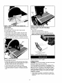
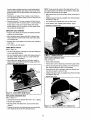
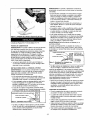
ATTACH ABRASIVE
• Combination Square
• Peel protective paper from the beck of the abrasive disc.
• Phillips Screwdriver
• Center the abrasive disc onto the aluminum disc and press
on firmly and evenly.
MOUNT
DISC.
Refer to Figure 4, page 4.
• Remove disc cover by loosening and removing four screws.
SANDER
• Replace disc cover.
Refer to Figures 2 and 3.
Choose a suitable location to mount the sander,The sander
must be installed in a place with ample lighting and correct
power supply. To install sander:
• The sander must be bolted to a firm, level surface.
• Make sure there is plenty of room for moving the workpiece.There must be enough room that neither operators
nor bystanders will have to stand in line with the wood
whila using the tool. Allow room so that belt assembly can
be positioned horizontally,
3
I
!
Figure 4 - Remove Cover and Attach Abrasive Disc
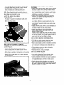
Figure 6 - Using Table with Belt
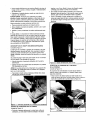
ATTACH TABLE
ATTACH
Refer to Figure 5 and 6.
The included table is used with both the disc and belt.
Refer to Figure 7,
•
Place clamp over bag sleeve.
To use the table with the disc:
•
Slide sleeve with clamp over the dust port.
• Position table on disc guard and attach using two knobs.
DUST
COLLECTION
BAG
Secure in position by tightening clamp handle. Do not
force handle. Rotate the handle to increase the clamp size.
• Thread locking handle through tal_e and into disc guard.
• Using a combination square, set the table perpendicular
to the disc, and secure in position.If necessary, set pointer
at 0°.
_gure 7 - Attach Dust Collection Bag
Figure 5 - Using Table with Disc
Refer to Figures 8, 9 and 10, page 5,
To use the table with the belt:
POWER SOURCE
• Position table between belt housing and disc guard. Place
the right side table slot over the stud located on the rear of
disc guard. Secure left aide of table using knob.
WARNING: Do not connect sander to the power source until
all assembly steps have been completed.
The motor is designed for operation on the voltage and frequency specified. Normal loads will be handled safely on voltages not more than 10% above or below specified voltage,
Running the unit on voltages which are not within range may
cause overheating and motor bum-out, Heavy loads require
that voltage at motor termlnals be no less than the voltage
specified on nameplate.
• Power supply to the motor is controlled by s single pole
locking rocker switch. Remove the key to prevent unauthorized use.
• Thread locking handle through table into bracket.
• Using a combination square, set the table perpendicular
to the belt and secure in position, If necessary, set pointer
at 0°,
4
GROUNDING
INSTRUCTIONS
grounded wire system,
WARNING: Improper oonnsction of equipment grounding
conductor can result in the risk of electrical shock. Equipment
should be grounded while in use to protect operator from
electrical shock.
• Many cover plate screws, water pipes and outlet boxes are
not propedy grounded. To ensure proper ground, grounding
• means must be tested by a qualified electrician.
EXTENSION
• Check with a qualified electrician if grounding instructions
are not understood or if in doubt as to whether the tool is
properly grounded.
• This tool is equipped with an approved 3-conductor cord
rated at 150V and a 3-prong grounding type plug (Figure 8)
for your protection against shock hazards.
• Grounding plug should be plugged directly into a properiy
installed and grounded 3-prong grounding-type recaptacle,
as shown (Figure 8).
Properly Grounded Outlet_
Grounding Prong...
CORDS
• The use of any extension cord will cause ,some drop in
voltage and loss of power.
• Wires of the extension cord must be of sufficient size to
carry the current and maintain adequate voltage.
• Use the table to determine the minimum wire size (A.W.G.)
extension cord.
• Use only 3-wire extansion cords having 3-prong grounc_ng
type plugs and 3-pole receptacles which acoapt the tool
plug.
• If the extension cord is worn, cut, or damaged in any way,
replace it immediately.
_'_
Extension Cord Length
Wire Size ...................................
A.W.G.
Up to 25 tl .......................................
25 to 50 ft .......................................
3-Prong Plug
Figure 8 - 3-Prong Receptacle
18
16
NOTE: Using extension cords'over 50 ft. long is not
recommended.
Do not remove or alter grounding prong in any manner. In
the event of a malfunction or breakdown, grounding provides a path of least resistance for electrical shock.
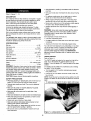
MOTOR
WARNING:
Do not permit fingers to touch the terminals of
plug when instaUing or removing from outlet.
The sander is assembled with motor and wiring installed. The
electrical widng schematic is shown in Figure 9.
• Plug must be plugged into matching outlet that is properly
installed and grounded in accordance with all local codes
and ordinances. Do not modify plug provided. If it will not fit
in outlet, have proper outlet installed by a qualified electrician.
MOTOR SPECIFICATIONS:
Horsepower (Maximum Developed) ....................
Voltage ........................................
Amp ...........................................
Hertz ..........................................
•
Inspect tool cords periodically, and if damaged, have
repaired by an authorized service facility.
Phase .......................................
RPM .........................................
• Green (or green and yellow) conductor in cord is the
grounding wire. if repair or replacement of the electric cord
or plug is necessary, do not connect the green (or green
and yellow) wire to a live terminal,
ELECTRICAL
CONNECTIONS
Motor and wires are instafied as shown in wiring schematic
(See Figure 10). Motor is assembled with approved,
3-conductor cord to be used at 120 volts.
This work should be performed by a qualified
Switch
A temporary 3,-prong to 2-prong grounding adapter (see
Figure 9) is available for connecting plugs to a two pole outlet
If It is propedy grounded.
•
Grounding Lug
Adapter...._
Make Sure This
W'_J.I-- Is Connected
"_,"'_11
To A Known
Figure 10 -Wiring
3-ProngPlu_._(_!
i.
_
2-Prong
Receptacle
(A 3-prong
Canada.)
to 2-prong
grounding
by local and nationaL] codes
to 2-prong
Where
grounding
permitted,
adapter
unless
• Remove the key to prevent unauthorized use.
and ord_nancas.
adapter is not permitted
the rigid green
tab or terminal
in
on
the side of the adapter must be securely connected
to a
permanent
electrical ground such as a properly grounded
water pipe, a properly
grounded
Motor
The power lines are inserled directly onto the switch. The
green ground line must remain securely fastened to the frame
to properly protect against electdcal shook. The power supply
to the motor is controlled by a single pole locking rocker switch.
:igure 9 - 2-Prong Receptacle with Adapter
permitted
_-- -_Schamati_
Ground
_'_-
Do net use a 3-prong
Single
1700
WARNING: An electrical connections must be performed by
a qualified electrician. Make sure tool is oft and disconnected
from power source while motor is mounted, connected, reconnected or anytime wiring is inspected.
• Where a 2-prong wall receptacle is encountered, it must be
replaced with a properly grounded 3-prong receptacle
installed in accordance with National Electdc Code and
local codes and ordinances.
WARNING:
electrician.
1
120
4.0
60
outlet box or a propedy
5
* Avoid kickback by sanding in accordance with the directional arrows.
Refer to Figures 11 - 38.
DESCRIPTION
The Graftaman Belt and Disc Bander is constructed of rugged
die cast aluminum and cast iron providing stabilityand vibration-free operation. The belt and disc are used to sand,
deburr, bevel and grind workpieces of wood and plastic.
The belt housing can be pivoted from vertical to
hodz.ontal for sanding large, straight workpisoes. The idler
drum permits the sanding of contoured shapes and finishes•
The disc can be used to sand or bevel surfaces.
Built in dust collection system collects dust from the belt and
disc and exhausts the dust into an included 30--micron collection bag.
The adjustable miter gauge is used on the work table for guiding the workplace at a desired angle while sanding. Work stop
included for sanding long pieces on the belt.
SPECIFICATIONS
Belt alze ....................................
4 x 36"
Belt platen area ...............................
5 x 9"
Bait speed ................................
Disc diameter ....................................
1100 FPM
8"
Disc speed ...............................
Table dimenalons ..............................
2200 RPM
6 x 9"
Table tilts ...................................
0 to 45°
Dust port diameter ................................
Base dimensions ............................
2"
12 x 17"
Switch .............................
Weight ......................................
SP, Locking rocker
551be
WARNING: Operation of any power tool can result in toralgn
objects being thrown into the eyes, which can result in severe
eye damage. Always wear safety goggles complying with
United States ANSf Z87.1 (shown on package) before commencing power tool operation. Safety goggtes are avaltable at
Sears retail stores or catalog.
CAUTION;
SAFETY
Always observe falio,Mmg safety precautions.
PRECAUTIONS
• Whenever adjusting or reptacing any parts on the tool, turn
switch OFF and remove the plug from power source.
• Keep your hands diear of abrasive belt, disc and all moving
part_.
• For optimum performance, do not stall motor or reduce
speed. Do not ferns the work into the abrasive.
• Always support workpiece with table or work stop when
sanding with belt and with table when sanding with disc.
• Never push a sharp comer ot the workpisoe rapidly against
the bert or disc. Abrasive backing may tear.
• Replace abrasives when they become loaded (glazed) or
frayed.
WARNING: Some dust created by power sar_ding, sawing,
grindiog, drilling and other construction activities contains
chemicals known to cause cancer, birth defects or other
reproductive harm•
Some examples of these chemicals are:
• Lead from lead-based paints.
• Crystalline silica from bricks and cement and other masonP/products.
• Arsenic and chromium from chemically-trsatad
lumber.
Your risk from these exposures vary, depending on how often
you do this type of work. To reduce your'exposure to these
chemicals: work in a well ventilated area and work with
approved salety equipment. Always wear MSHA/NIOSH
approved, properly fittiog face mask or respirator when using
such tools.
ON/OFF SWITCH
Refer to Figure 11.
The ON/OFF switch is located on the upperfront right of the
base.To turn the sander ON, puff the switch to the up
position. To turn the sander OFF, push the switch to the down
position.
The sander can be locked from unauthorized use by locking
the switch. To lock the switch:
* Turn the switch to OFF position and disconnect sander
from power source.
• PuE{the key out, The switch cannot be turned on with the
key removed.
NOTE: Should the key be removed from the switch at the ON
position, the switch can be turned of_but cannot be turned on
again.
* To replace key, slide key into the slot on switch until it snaps.
• Recheck table handle and bolts.They must be tightened
securely.
• Make sure all guards are properly attached. All guards
should be securely fastened.
• Make sure all moving parts are free and clear of any
interference.
• Make sure all fasteners are tight and have not vibrated loose.
• With power disconnected, test operation by hand for clearance and adjust it necessary.
• Always wear eye protection or face shield.
• Make sure abrasive belt always tracks properly. Correct
tracking gives optimum performance.
• After tumthg switch on, always allow belt and disc to come
up to full speed before sanding or grinding.
• Be sure disc turns counterclockwise. Abrasive belt must
travel downward.
11- Locking
Switch in OFF Position
ADJUSTING
BELTTRACKING
RefertoFigure 12,
• Quickly turn the sWitch ON and OFF to check the traskJng.
Be]t should ride centered on idler and drive drums. Adjust
tracking nut as needed to center belt on drums.
• If belt moves to the left, turn tracking nut to the right, If belt
moves to the right, turn tracking nut to the left.
• Quickly turn switch ON and OFF again, if belt moves to one
side, continue adjusting tracking nut as needed to center
belt on drums.
• Adjustable positive stops are provided for both horizontal
and vertical positions.
NOTE: The horizontal limit stop is located on top of the base
and the vertical limit stop Is located beneath belt cover.
ADJUSTING
TABLE ANGLE
Refer to Figure 14.
• To adjust table angle, loosen handle, tilt table to desired
position, then secure by tightening handle.
Tracking Nut
Figure 14 -TableTitts
Tension Lever
/
HORIZONTAL
Down to 45_
BELT SANDING
WITH WORK STOP
Refer to Figure 15.
• Remove table from belt assembly.
• Tilt beti assembly from vertical to horizontal position and
secure in position.
• Mount work stop to belt assembly using the two bolts.
• idler drum can be used as a contact drum to sand surfaces.
Figure 12- Adjusting BeltTracldng
ADJUSTING
BELT ASSEMBLY
POSITION
Refer to Figure 13.
Sanding belt assembly can be adjusted from vertical to
horizontal position, or any angle in between.
• Loosen socket head bolt that is threaded into pivot bracket.
Bolt is accessed through belt cover (see Figure 13).
Figure 15 - Attaching the Work Stop
ABRASIVE BELT SANDING
• Finishing flat surfaces: Hold work,piece firmly with both
hands; keep fingers away from abrasive belt.
Use table to position and secure work being sanded. Keep
end butted against table and move work evenly across
abrasive belt.
Figure 13 - Loosen Bolt to Tilt Belt Assembly
• Tilt belt assembly to desired position. Secure belt assembly
position by tightening socket head bolt in pivot bracket.
•
Finishing long pieces: Use belt in horizontal
position with
work stop. Apply only enough pressure to allow abrasive
belt to remove material.
Use work stop to position and secure work being sanded.
Keep end butted against work stop and move work evenly
across abrasive belt, Use extra caution when finishing very
thin pieces.
• Finishing curved edges: Finish outside curves on flat portion of abrasive bell Finish inside curves on idler drum portion of abrasive belt.
• Finishing sod grain: It is more convenient to finish ends of
long workpiecss wild the abrasive belt in a vertical position.
Position table on belt side of sander. Move work evenly
across abrasive belt. For accuracy, use miter gauge. Table
may be tilted for beveled work.
NOTE: There may be an arrow on the inside of the belt.The
arrow should point in the direction of belt travel to ensure that
the splice in the belt will not come apart.
• Slide new belt over the drive and idler drums; center belt on
drums.'
• Additional abrasive belts are available (See Recommended
Accessories, page 13).
• Push tension lever towards drive drum to tension belt.
• Check tracking. See "Adjusting Belt Tracking", page 7.
• Assemble in reverse order,
ABRASIVE DISC SANDING
• Abrasive
surfaces
•
disc sanding is well suited for fitlishing
and convex edges.
Move workpiece
across
Hold workplace firmly
from abrasive disc.
small fiat
down side (left) of abrasive
with both hands;
disc.
keep fingers
away
• Abrasive disc moves fastest and removes more material at
outer edge.
• For accuracy, use miter gauge,
USING
MITER
GAUGE
Refer to Figure 16.
• Use the miter gauge for secudng the work and holding the
proper angle while sanding.
• Use a combination square to adjust miter gauge square to
belt (disc). Pointer should be at zero. Loosen screw and
reposition pointer if necessary.
• After setting miter gauge square to belt (disc), adjust to
desired angle by repositioning the miter gauge ssale and
locking it into place with knob.
REPLACING ABRASIVE
Refer to Figure 18.
DISC
• Remove table assembly.
• Remove disc cover by loosening and removing four screws.
• Remove old abrasive disc by peeling it from the aluminum
disc, Removing aluminum disc is not necessary.
Pointer
• Clean aluminum disc if necessary. Select the desired abrasive disc and apply to aluminum disc.
• Additional abrasive discs are available (See Recommended
Accessories, page 13).
Replace disc cover.
Figure 16 - Setting Miter Gauge Square
REPLACING
ABRASIVE
Refer to Figure
17.
BELT
• Sanding
belt should
be replaced
when worn, torn, or glazed.
•
Remove
table assembly.
•
Remove pointer,
deflecteL
•
Release belt tension by pushing tension lever toward
drum. Slide old belt off the drive and idler drums.
then slide cover up and out from
dust
Figure 18 idler
LUBRICATION
The shielded ball bearings in this tool are permanently
lubricated at the factory.They require no further lubrication.
WARNING: Make certain that the unit is disconnected from
power source before attempting to service or remove any
component.
• When operation seems stiff, a fightcoat of paste wax
applied to the table will make it easier to feed the work
while finishing.
CLEANING
• Do not apply wax to the belt platen. Belt could pick up wax
and deposit it on wheels causing belt to slip.
Keep machine and workshop clean. Do not allow sawdust to
accumulate on the tool Keep the drums clean. Dirt on drums
will cause poor tracking and beti slippage. Periodically empty
the dust collection bag.
KEEP TOOL IN REPAIR
• If power cord is worn, cut, or damaged in any way, have it
replaced immediately.
Be certain motor is kept clean and is fraquentiy vacuumed
free of dust.
• Replace worn abrasives when needed.
• Replace any damaged or missing parts. Use parts list to
order parts.
Use soap and water to clean painted parts, rubber parts and
plastic guards.
Any attempt to repair motor may create a hazard unless
repair is done by a qualified service technician. Repair
service is available at your nearest Sears store,
SYMPTOM
Motor willnot start
POSSIBLE
CORRECTIVE
CAUSE(S)
1. Low voltage
;2. Open circuit in motor or loose
ACTION
1. Check power line for proper voltage
2. Inspect all lead connections on motor for loose or
open connection
3. Replace switch
4, Replace capacitor
connections
3. Defective switch
4. Defective capacitor
,,lotor will not start;
fuses blown or circuit
1. Short cimuit in line cord or plug
1. Inspect line cord or plug for damaged
shorted wires
breakers
2. Short
2. Inspect al! lead connections
on motor for loose or
shorted terminals
or worn insulation on wires
are tripped
ci_uitin
motor orloose
ccnne_on$
3, lncorrectfuses
or slmuit braake_
in
3. Install correct fuses
insulation
and
or circuit breakers
power[ine
Motor fails to develop full 1, Power line overloaded with lights,
appliances and other motors
)ower (power output of
motor decreases ra.pidly 2. Undersize wires or circuits too long
with decrease in voltage ;3. General overloading of power
at motor terminals)
company's facilities
1. Reduce the load on the power line
Motor overheats
Motor overloaded
Reduce
victor stalls (resulting in
blown fuses or tripped
circuit breakers)
1. Short circuit in motor or loose
connections
1, Inspect connections in motor for loose or shorted
terminals or worn insulatipn on lead wires
2. Correct the low line voltage conditions
3. Install correct fuses or circuit breakers
2. Low voltage
3. Incorrect fuses or cimuit breakers in
power line
4. Motor overload
2. Increase wire sizes, or reduce length of wiring
3. Request a voltage check from the power company
load on motor
4. Reduce load on motor
Machine slows down
while operating
Applying too much pressure to workplace
Abrasive belt runs off top
wheel
Not tracking properly
See operation "Adjusting Belt Tracking"
Dust collection
not working
1, Dust collection
1. Empty dust collection bag
2. Replace belt
3. Raplaoe impeller
bag full
2. Belt loose or broken
3. impeller
loose
or broken
9
:Ease up on pressure
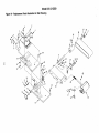
Model
351.215200
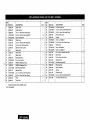
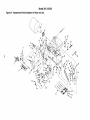
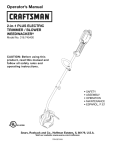
Figure 19 - Replacement Parts Illustration for Belt Housing
2
37
//,
4
/
36
35
4
34
11
/
18
43
?
t
26
15,_
39
KEY
NO. PART NO.
If.
DESCRIPTION
QTY,
KEY
NO.
PART NO.
DESCRIPTION
STD840508
STD870516
5-0.8mm Hsx Nut*
5-0.8 x 16ram Socket Head Bolt*
1
2
QTY.
1
23682.00
Side Cover
1
2
23683,00
Dust Deflector
1
23
24
3
08686.00
4-0,7 x 15ram Pan Head Screw
1
26
STD863510
5-0.8 x 10mm Pan Head Screw*
1
23694.00
Platen with Label
1
4
STD870510
5-0.8 x 10ram Socket Head Bolt*
12
26
5
8TD851005
5ram Fiat Washer"
5
27
23695.00
Pointer
1
6
7
23684.00
05374.00
Dust Cover
5-0.8 x 15ram Socket Head Bolt
1
2
28
STD852005
5ram Lock Washer*
1
2g
STD863508
5-0,8 x 8mm Pan Head Screw"
1
5-0,8 x 8mm Flat Head Bolt
1
30
31
23696.00
8TD851006
Work Stop
6ram Flat Washer*
1
2
32
STD852006
6mm Lock Washer*
2
33
34
05376,00
23697.00
6-1.0x15mm Socket Head Bolt
Drive Drum
2
1
5
01833.00
9
i 23685,00
Belt Cover with Labels
1
10
11
N/A
23681.00
Base Plate
Drive Shaft:
1
1
12
N/A
Base Cover
1
Horizontal Stop
8-1.0ram Hex Nut*
1
1
35
01044.00
6-1,0 x 8mm Set Sersw
2
36
20613,00
Abrasive belt
1_
3AMI-50 Retaining Ring
35M|-32 Retaining Ring
1
2
37
STD315505
Ball Bearing 6O00ZZ*
1
38
23698,00
Bearing Plate
1
23699.80
23700.00
23701.00
Idler AssemblY
Spring
Tension Lever
1
1
1
13
14
23689.00
i STD840812
15
16
23690,00
18366,00
17
STD315525
Ball Bearing 6002ZZ*
2
18
19
23691.00
STD670625
Vertical Stop
6-1.0 x 25mm Socket Head Bolt*
1
1
39
40
41
20
03856.00
5-0,8 x 12ram Flat Head Screw
8
42
8TD870620
6-1,0 x 20ram Socket Head Bolt*
1
21
23692.00
Pivot
1
43
05153,00
6-1.0mm Fiber Hex Nut
1
22
23693.00
Pivot Stop
2
Standard hardware item available locally.
N/A Not available.
Model
351.215200
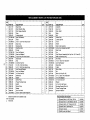
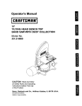
Figure 20 - Replacement Parts Illustration for Motor and Disc
3
3O
33
48
46
51
KEY
NO. PA_TNO.
1
22121.00
2
22122,01
3
23721.00
4
23653,00
5
23654.00
6
STD851006
7
23722.00
8
STD863612
9
23723,00
10
20591.00
11
23734.00
12
23658.00
13
STD851005
14
STD852005
15
STD863508
16
23724.00
17
23669,00
18
STD840506
19
07202.00
20
08685.00
21
05156,00
22
STD852004
23
STD640407
24
23660,00
25
23661,00
26
23725.00
27
23662.00
28
16060.00
29
23663.00
30
23749.00
31
23666.00
32
STD870510
DESCRIPTION
Bag Clamp
Dust Collection Bag
Miter Gauge Assembly
Knob
Locking Handle
6ram Flat Washer*
Table
5-0,8 x 12mm Pan Head Screw*
Disc Cover
Abrasive Disc
Aluminum Disc
Pointer
5mm Flat Washer*
5mm Lock Washer*
5-0,8 x Bmm Pan Head Screw*
Disc Guard
Stud
5-0.8mm Hex Nut*
8-1,25 x 10ram Set Screw
4-0.7 x 15mm Pan Head Screw
4ram Serrated Washer
4mm LockWasher*
4-0.Tram Hex Nut*
Switch Box
Gasket
Switch Plate
Thread Forming Screw
Switch
Driven Pulley
Gasket
Line Cord Hook
5-0.8 x 10mm Socket Head Bolt*
Standard hardware Item available locally.
N/A Not available,
&
Not shown.
QTY,
1
1
1
2
1
1
1
7
1
1
1
1
7
3
1
1
1
1
5
2
2
8
2
1
1
1
3
1
1
1
2
4
KEY
NO.
33
34
35
36
37
38
39
4O
41
42
43
44
45
46
47
46
49
50
51
52
53
54
55
56
57
56
59
60
61
62
&
PART NO.
23750.00
16921.00
23665,00
,N/A
23668.00
23669.00
23670,00
23671.00
23672.00
23726.00
STD870508
23728.00
123729.00
23730.00
16254,00
:23731.00
STD863410
STD651004
23732.00
23676.00
23677.00
23676,00
23733.00
STD836025
STD851010
STD841015
23664.00
01043.00
23744.00
22512.00
23736.01
DESCRIPTION
Capacitor
Line Cord
Strain Relief
Body
Bolt
Rubber Pad
2.5ram Split Pin
Foot A
Foot B
Dust Chute Assembly
5-0.8 x 6ram Socket Head Bolt*
Dust Chute
Fan
Dust Collector Assembly (incl. Key Nos. 13.32 and 45)
3BMI-26 Retalnln_l Ring
Fan Pulley
4-0.7 x 10turn Pan Head Bolt*
4ram Flat Washer*
Base Plate
V-Belt
Motor Pulley
Nut
Motor (incl. Key No. :33)
10-1.5 x 25mrn He× Head Bolt*
10ram Flat Washer*
10-1.5mm Hex Nut*
Wrench
6-1.0 x 6mm Set Screw
Mounting Bracket {Set of 4)
Thread Forming Screw
Operator's Manual
QTY.
I
I
I
I
1
1
I
2
2
I
5
I
I
I
I
I
6
6
I
I
I
I
I
2
2
2
I
I
I
I
I
Recommended Accessories
&
Abrasive Belts 4 x 36" {Fine) 120 Grit
Abrasive Belts 4 × 36" {Medium) 80 Grit
9-28394
£,-28395
A
Abrasive Belt 4 x 36" {Coarse) 50 Grit
Abrasive Disc 8" Assorted Grit
Abrasive Cleaner
9-28396
9-26316
9-28000
A
Multi-PurposeTool Stand
9-22224
LIJADORA CON RECOLECTOR
DE POLVO
•
Use ura oubierta
cabello largo.
•
Use zapatos de segufidad con suelas antideslizantes.
•
Use galas de segurldad qua cumplan con le norma ANSI
Z87.1 de los Estedos Unidos. Los anteojos comunes tienen
Correa de 4 x 36"
Disco de 8"
protectors
p_.r_ el cabello, pars sujet_r el
lentes qua s61o son resistentes
de seguridad.
Modelos No.
351.215200
PRECAUCION:
Lea y siga testes las reglas de
seguridad e instrucciones de operaci6n antes de
utilizer este producto per pdmera vez. Mantenga
este manual junto con la herramienta.
al impasto. NO son anteojos
•
Use ur_ rn_scara pars la cars ouRa m_scara corltra e] po[vo,
sial utilizer la herramiante se produce touche polvo.
•
Est_ alerts y pier_se claramente. Nunca opera herramientas
msc&nicas cuando est@ ca.nsade, intoxicado o bajo la influerlcia de meciicaci6n que produzca somnolencia.
PREPARE EL AREA DETRABAJO
REAU7_AR
PARA LATAREA A
• Mantenga el &rea de trabajo limpia. Las _,reasde trabajo
desordenadas atrasn aocidentss.
• No use herramientas mec_nicas en ambientes peligrosos. No
use herramiantas mec_.rYicas en lugares ht_medse o mojades.
No exponga tes herramientas mec_nicas ata Iluvia.
Ingl6.s .........................................
Ilustraci6n y Lists de Partes ......................
Garant(a ......
"..................................
Reglas de Seguridad ...........................
Desempaque ....................................
Montaje ......................................
Instalaci6n ....................................
Operaci6n ....................................
Mantenimianto ................................
Identifisaci6n de Problamas .........................
2-g
10-13
14
14-15
15
15-17
17-18
18-21
21-22
23
• El &rea de trabajo dabs ester iluminade adecuademente.
•
Dsbe haber disponible una toms de cements adecuade pars
la herramiante. El enchufe de tres puntas debe snohufarse
dffectamente aun receptdoulo pars tres puntas puestoa
tierra correctemente.
•
Los oorOones de extensi6n deben tener una punts de conexi6n a tierra y los tres alambres del cord6n de extensi6n
deben ser del calibre correcto.
•
Mantenga a los visitantes a una distancia prudente del drea
de trabap.
•
Mantanga a los nifios fuera del lugar de trabajo. Hags que
su taller sea a prueba de niSos. Use cand_dos, interruptores
maestros y remueva las Uaves del arrancador pars impedir
cualquier use involuntario de las herramiantes mec_,nioss.
GARANT|A COMPLETA DE UN A_IO PARA HERRAMIENTA
CRAFTSMAN
SE DEBE
Si esta herramienta Craftsman tellers per cause de detectos en el
material o en la mane de obra en un lapse de un a_o a partir de
la tachs de ¢ompra, LLAME a 1-800-4-MY-HOME® PAPA
SOLICITAR LA REPARACION GRATUITA DEL PRODUCTO.
Siesta herramienta se usa pars fines comerciales o de alquiler,
esta gamntia es v_lida ,',nicamente per noventa dies a partir de
la feoha de compra.
Esta gamntia aplloa L_nicamente si la herramienta
en los Estados Unidos.
Desenehufe siempre
•
Consults el manual pars informarse sobre los proceciimientos
de mantenimianto y ajuste espec_ficos.
•
Mantenga la hermmienta lubdsade y limpia de mode qua
funcione de la manera m&s segura.
•
Retire las herramientas de a.juste. Desa.rrolle el hdbito de
vedficar qua haya_ side retirades las herramientas de ajuste
antes de encender la re&quirts.
•
Mantenga redes las partes ti_tas para funcionar. Revise el
protector u otras plazas pare determinar si funcionan oorrectamanta y hacen el trabajo que deben haoer.
•
Revise qua no hays partes dafiadas. Verifique el alineamiento
de las p_rtes m6viles, sl hay atascamiento, refutes y montaje o
eualquier otra condici6n qua pudier_ afe_tar el funcionamianto
de le herramienta.
•
Si hay une proteoni6n o eualquier otra parts decade, _stas
deber_n repararse oorreetamente o ser reemplazades. No
hags reparaoiones provisionales (valgase de la list_ de
partes incluida pars solicitor partes de repuesto).
puede usted tener otros dereehos qua vaffen de estado a estado.
Sears, Roebuck and Co., Dept. 617WA, Hoffman
60179
Estates,
IL
ADVERTENCIA:
Pare su propia seguridad, lea redes las
ir_stnJosianes y las precauciores antes de odemr la herrarnienta.
PRECAUCION:
Siempre siga los procsdimientos de operaci6n
correctos, tel come se ctefinen en este manual, sun cuando
est6 farniliarizado con el use de _.sta o de otras hemarnientas
EL OPERADOR
DEBE
LA HERRAMIENTA
eimilares. Recuerde qua desouidarse aunque e61o sea per
una fracci6n de segundo puede ocasionade graves lesiones.
•
EL OPERADOR DEBE ESTAR PREPARADO PARA
ELTRABAJO
*
A LA HERRAMIENTA
•
se encuentra
Esta garant{a le otorga detaches legales especffic, os y tambi6n
DAR MANTENIMIENTO
la herrarnienta antes de inspeceionafla.
SABER
COMO
USAR
Use la herramienta corrects pars cede trabajo. No fueros la
herramiant_ o el accesorio ni los use pars une tar_
qua no fueron diseSados.
•
Usa ropa apropiada. No use rope holgada, guantes, corbatas,
anillos, pulsems ni otras joy'as qua puedan atasc_rse an las
plazas m6vites de la re&quirts.
14
Desconecte la herramienta
disoo abrasive.
pars la
euando carnbie le correa o el
•
Evite que la herramienta se encienda accidentalmente.
Asag,3rese que el interrupter de la herramienta esti en la
poaici_q OFF (apagado)
•
No fuerce la herramienta.
ciente a ia velocidad
Funoionar_
en la forms m_is eft-
\
pare la cu_,l sa disafi6.
• Mantenga [asmanes alejadasde laspartes moviblesy de
tas superficies lijantes.
•
A
\
c
antes de enchufada.
Nunca deje desatendida una herramianta en funcionarniento.
Desoon_ctela y no abandons el lugar hasta que se hays
detenide per complete.
• No trate de alcanzar demasiado
equilibrade.
_
Is)as. Mant6n{:jase firme y
E
F
!Figure 1 -Desempaque
de la Lijadora
i
•
Nunca sa pare sabre la herramienta. Se pueden producir
lesiones graves sJ la herramienta se vuelca o se toca accJderr
talmente ta correa o el disco.
• Oonozca su herramienta. Aprenda a manejar la herramienta,
su aplicaci6n y limitaciones espec[fices.
Consults
•
PRECAUCION:
faltan. V_gasa
•
Use los accesorios recomendedos
Si se usan accesorios incorrectos,
_esionar e alguien.
(consulte la p_,gins 13).
puede sufrii- lesiones o
•
No opera la mAquina haste qlJe eat4 completamente armada. No opera la m&quina haste que haya leido y
entendido totalmente este manual.
Maneje la pieza de traba)o en forms correcta. Prot4jase las
manes de posibles qesiones.
HERRAMIENTAS
NECESARIAS
penetm muy profundamente en lapJeza de tmba)o (Isfuerza
del motor la malhtiene trabada en la pieza de traba)o).
Cuando arme e ajuste la lijadora de disco y correa, necesitar_
Soporte la plaza de trabajc; con la guia de ingletes, la platina
•
Uaves hexagonales
de la correa o la mesa de traba)o.
•
Escuadra de combinaci6n
Mantenga un eapacio libra m_Lximo de V,,/' entre la mesa y la
eorrea o e[ diSCo abrasive.
•
Destomi[lador
PRECAUCION:
iPiense
en la saguridad!
La saguddad
ias herramientae
es una
MONTAJE
¢ombinaci6n de[ sentido comL_ndel operador y un estade de
alerts permanente ad usar ]a herramienta.
ADVERTENCIA:
No trate de operar la herramienta
hays side completamente
Consults
armada seg,',n las instnJcciones.
de 3 y 5 mm
Phillips
LIJADORA
las Figures 2 y 3, en las p&ginas 15 y 16.
La lijadora se debe empernar a one superficie
firms y nivelada.
• Asegdresa qua hays eut]ciente espacio pare mover
trabajo. Deber_ haber suf_iente espacio de manera
operadores ni dem&s personas tengen qua situarse
la pieza de trabajo mientras sa usa le herramienta.
qua haya suficiente espacio pare poner en posici6n
eloonjuntode laoorrea,
Cortsutte la Figure 1.
Verifique qua no hayan ocurrido dares
DE t!
siguientes:
Elija un tugar adecuado para inatalar La lijadora. La lijadora debe
instalarsa en un lugar qua cuents con suficiente iluminaci6n y
una fuente de alimentaci6n adecuada, pare instalar Le lijedora:
basra qua
•
durante el env[o. Si hay
da6os, se deber_ presenter un reclamo a la ¢ompafia de trans.
porte. Verifique que eat6 complete. Arise inmediatamente al
di_tribuidor _i faltan partes.
Lijadora
la pieza de
qua ni )as
detri_ de
Permits
horizontal
•
La lijadora se puede inetalar en un banco de trabajo o una
plataforme pare herramientas (consults La secci6n Acce$orios
Recomendados, en la pagiPa 13) usando pemos, arandelas
de saguridad y tuercas hexagonales y soportes de montaje
(inoluye).
•
Optima una pete en cada sequins de la base de la lijadora.
La lijadora viene montada come una unidad. Es necesario
}ocalizar y tamer en ouenta las piezas adicionales que deben
asegurarse a Is IJjadora antes de armada:
A
No intents hacer el montaje si hay partes que
de ests manu_J pare solicitar partss de repueste.
ADVERTENCIA:
• Apague lam_quina slse atasca.La comma se atasca cuando
•
las Figuras 2-6.
B Tope de seguridad
C Mesa
D Balsa de recoleo¢i6n de polvo
E Abrazadera
de la balsa
F Conjunto de la gu[a de ingletes
G Manilla con arandela
No sa muestra: Disco abrasive, Pedlla (2), Base (4), Sol)oRe de
mc,ntaje(4), Pemo de cabeza hexagonal de M6 x 16 (4), Pemo
de cabeze hueca de M6 x 16 (2), Arandela de saguridad de M6
(2), Aradela plane de M6 (6), Tuerca hexagonal de M6 (4) y Lleve
hexagonal de 3 y 5 mm.
SopoFtes
/
;igura
15
2-
de Montaje
Inserte los Soportes de Montaje en las Renuras
de la Base de la Lijadora
• La Rgura 3 muestra i_s dimensiones de la base, los oriflclos
de montaje y el espaoio necesado pare colocar el conjunto
de la mesa y el conjuntode la cortes en posici6n horizontal.
Perilta
L
24"
12" --.,,_
Figure 5 - Uso de la Mesa con el Disco
Pare utilizer la mesa con le correa:
f
_=
Figure 3 - Espaeio Necesario y Dimensiones
FIJACION
Consulte
•
DEL
de la Base
mesa sobre el pemo pdeicnero ubicado en ta parte posterior
de la protecciSn del disco. Asegure e[ lado izquierdo de ta
mesa haciendo uso de ta pedna.
DISCO ABRASIVO
la Figure 4.
Retire la cubierta
tomillos.
del disco. Pare eeto, afloje y extraiga
• Retire el recubdmiento
•
• Coicque La mesa entre el alojamiento de la correa y le protecci6n del disco. Coloque ta ranura en el lado derecho de la
18"
Coicque
de ta porte posterior
•
Enrosque
soporta.
*
Usando una escuadra de combinaci6n, coloque ta mesa en
poslci6n perpendicular
ala cortes y fOela en esa posici6n. Si
es necesario, aJuste el indicader a 0 °,
cuatro
del disco abrasive.
el disco abrasivo en el centro del disco de aluminio y
presibnelo
con tirmeza
la manija de fijaci6n a tray,s de la mesa en el
y de forms pareja.
Vuelva a instatar la cubierta del disco.
Figure 6 - Uso de le Mesa con la Correa
INSTALACION
DE POLVO
Figure 4 - Extraooi6n de la Cubierta y Fijacibn del
Disco Abrasivo
INSTALAC|ON
DE LA BOLSA
DE RECOLECCION
Consulte la Figure 7 en la p_gina 1T.
DE LA MESA
Consulte tas F'iguras 5 y 6.
•
Coloque la abrazadera
El mesa incluido sa utilize con ambes, el disco y Lacorrea.
•
De.slice la mange con Laabrazadera
de] polvo.
•
Fije en eu lugar apretande
Para utilizar la mesa con et disco:
•
Coloque la mesa en la protecc_6n del disco y fije con las dos
periUes.
• Enresque la manija de fijacibn
protecoi6n del disco.
a tray,s
sobre la manga de La boise.
sobre el orificio de salide
la manilla de la abrazader_. No
fuerce ta manija. Gire la manilla para aumentar
la abrazadera.
de la mesa y had=a la
• Usando una escuadra de combinac_tbn, ooicque la mesa en
posici6n perpendicular al disco y fijela en esa posici6n. Si e_
nesesario, ajuste el indicador a 0 °.
16
el tamaSo de
ADVERTENCIA:
tomaconiante,
o el ecohufe.
AI conectar
o desoonectar
el enchufe del
no perrnita qua los dodos toquen los terminales
•
El anchufe debe conectar_e en el tomacorriente correspondiente qua haya sido instatado y conectado a tierra dabidareente, de acuerdo con todos los c_,digos y regulaeiones
locales. No reodifique el enchufe qua se incluye. Si no cabe
en el tomacorriente, solicite a un electricista caiificado que
instale un tomacorriente adecuado.
•
Revise periSdicamente los cordones de la herramienta y si
est&n daSados, 116velos a un cantro de servicio autorizado
pare qua los reparen.
•
El conductor verde (o verde y amarillo) del cord6n es el cabte
de oonexibn a tierra. Si es nacesatio reparar o reerepLazar
el corddn electrioo o el enchufe, no conecte el cable verde
(o verde y amadno) a un terminal cargado.
•
Si sa cuenta t_nicamente con un zbcaJo para dos elavijas,
_ste deber_ ser reemplazado con un zScalo pare tree clavijas
debidemente coneotado a tierra e instalado de acuerdo con
=igura 7 - Instalaci6n de la Boise de Re¢olecci6n de Polvo
las Normas pare Instalaciones El_ctric_s (National Electric
Code) y los ¢6digos y regulaciones locales.
Consulte las Figures 8,9 y 10 en las pdginas 17 y 18.
ADVERTENCIA:
Esta taree deber_ ser realizade por un
electricista caliticado.
FUENTE
Se puede user temporatreente
un adaptador de 3 puntas a 2
puntas con conexiSn e tJerra (vSa_e la Figure 9) para conectar
los enchufes a un toreacorriente bipolar que est_ correctamente
puesto a tJerra.
DE AUMENTACION
ADVERTENCIA:
No conecte la lijadom e la fuente de alimentaci6n haste haber cureplido todos los pesos del ensamblaje.
El motor ha sido dise£=ado pare funcionar al voltaje y lrecuencia
espec_ficados. Las cargas normales se pueden manejar sin
riesgos dentro de un intervalo de[ 10% resdecto al voltaje
Orejeta terminal de tierra \
Adaptador _
especificado. Si sa hate funeionar la unidad a un voltaje fuera
de eete intervalo, se puede rec_lentar y quemar el rector. Las
cargas pesadas exigen qua el voltaje en los terminales
motor no sea infedor al especificado.
•
Eoshufe de3 puntas _'_'
ADVERTENCIA:
equipo debe ester conectado a _erra mientras se usa pare
proteger al operador de un electrochoque.
tuberia de agL_ debidareente conectada a tierr_, un tomacorriente debidamente eonectado a tierra oun sistema de
cables debid_Lmente conectado a tierra.
Si no 0oreprende tas instruosionee de conexi6n a tierra o
tiene dudes en cuanto a eila herramienta est& correctamente
coneotada a tierra, consuffe a un eleotricista calificado.
• Muchos de los tomillos de la planoha de cubiert_, las 0Jbedas
de ague y las cajas de toreacorriente no est&n debidamente
conectados a tierra. Pare garantizar qua la conexiSn a tierr_
sea elective, un etectdeista calificado debe verificar los
medics de conexi6n a tierra.
• A fin de protegedo contra una desca_a el6ctrica, esta herrareienta esta equipada con un cable de tres conductores
aprobado y dasificado pare 150 V, as{ come con un enchufe
de tree clavijas 8po conexiSn a tierm (Figure 8).
•
para enchufe
de 2 puntas
(Este tipo de adaptadores no sa pen'niten an Cacad_.). Cuaodo
est6 permitido utilizer este tipo de adapt_dores, la lengSeta rigida
de _or verde o el terminal en el lade del adaptador deber&n
ester bien ¢onectados a una tierra perrnanente, como seda una
_Iconductor
a tierra del equipo, sa corm el riesgo de un electrochoque. El
•
una ,erra conosida
No utilice este tipo de adaptadores a menos qua est_ permitJdo por los cSdigos y regulaciones nadonales y locales.
A TIERRA
$i no sa conecta correctamente
''
-_"_k
Figura 9 - Reoept_culo con Adaptador para
Enchufe de 2 Puntas
pare evitar el uso no aut_rizado.
PARA LA CONEXION
'_'l_'j
del
La fuente de alimentaci_ del motor estd controlada por
un interruptor oscilante enclavado unipolar. Extraiga la 1lave
INSTRUCCIONES
=======_t_
AsegL_resa qua
L_t'_l - 6s'_ conectado a
El enchufe de conexiSn a tierm deber_ conectarse directamanta a un reoept&culo pare 3 ctavijas debidamente instalado
y oonectado a tierr_, tel como se muestra (Figura 8).
CORDONES DE EXTENSION
•
El uso de cualquier tipo de oord6n de extensi6n ocasionar_
una ca/de en el voltaje y una I_rdida de potencia.
• Los cables del cord6n de extensi6n deden tener el tamaSo
suflclente pare conducir la corriente adecuada y mantener
el vdtaje correcto.
•
Utilice _a table pare determiner el tamaSo m_nimo del alambre
(seg_n la norma AWG) dM cordSn de extensi6n.
•
Utilice L_lnicareente oordones de extensi6n trifilares qua tengan
enchufes tipo conexiSn a tierra de tree puntas y recapt&culsa
tdpolares qua acepten el enGhufe de la herrareienta.
'Figure 8 - Recept_culo pare 3 Pu_as
• No retire ni reodiflque en forma alguna la punta de conexi0n
a tierm. En caso de un maJfuncionareianto o una descorepostun, la conexibn a tierra proporoione una ruta de manor
resistencia pare la descarga el_ctfica.
•
Si e! cordSn de extensiSn est,. deegastado,
en cuaiquier forma, reempl&calo
17
roto o daSado
inmediatamente.
Longitud del ¢ord6n de extensi6n
TarnaF_odel alambre .........................
Norma AWG
Hasta 25 pies .......................................
18
25 a 50 pies ........................................
16
La gufa de ir_letes a_ustable ss utiliz_ en la mesa de traba}o
pare guiar la pieza de trabajo en el _.hgu_o daseade ¢uando se
lija. Ss incluye un tope de seguddad pare lijar piezas largas con
la cortes.
AVISO: No se recomienda utiliz_ar cordonss de extensidn de
ESPECIFICACIONES
m_s de 50 piss de largo.
Tamafio de la corrsa
MOTOR
_rea de la platina de la cortes
Velocidad
La lijadoraviene con el motor y el cableado instalados.La
Figure7 muestra el diagrama dsl cableadoeldctdeo,
ESPECIFICAC!ONES
Voltaje
1
2200 RPM
de la mesa ...........................
6 x 9"
0 a 45 °
2"
Dimensiones de la base .........................
60
Intsrruptor ...................
Monof,=_sico
RPM ............................................
B"
del disco ............................
Di&mstro del orificio de salide del polvo ..................
4.0
(Hz) .....................................
Fase .......................................
1100 PPM
In¢linacidn de Is mesa ............................
120
.........................................
Frscuencia
5 x 9"
de la _orrea .........................
Dimsnsionas
desarTollade) ....................
...........................................
Amperaje
4 x 36"
......................
Didmetro del disco ...................................
Velocldad
DEL MOTOR
Potencla en lip (m_ima
.............................
12 x 17"
Basculante enclavade unipolar
Peso ...........................................
1700
ADVERTENCIA:
El fun_ionamient0
55 Ibs
de todas las herramientas
CONEXIONES ELECTRICAS
ADVERTENC|A: Un slectdcista calificadodebe baser todas
tas conexionas el_ctdcas.Assg_rese que la herramientaest_
apagada y desconectadade ta fusnte de ensrgfa el_ctdca
mientras monte, conects o vuelva a conectarel motoro
mientras inspections e( cableado.
mec&nicas puede hacer que sean lanzados a los ojos cusrpos
extrafios, Io cual pusde lesionarlos gravemente. Siempre use
galas de seguddad que cumplan con los requisitos de la norms
estadounidense ANSI Z87.1 (se indies en el paquete) antes de
comenzar a user la herramienta met&nice. L.as galas de segundad se encuentran disponiblas a trav@s de las tJendas o el
El motor y los cables se instalantelly corns se muastra en el
diagrama de cableado (v@aseta Figure 10). El motor se instals
con ughcable de 3 conductoraspa.rafuncicoar a 120 voltios.
PRECAUCION:
cat_ogo
de Sears.
Tenga _iempre en cuenta tas sigulentes
precaLiCiotles.
PRECAUCIONES
Interruptor
DE SEGURIDAD
• Cuande ajusts o ¢ambis partas ds la herrarnienta, sismprs
APAGUE la unidad y desconecte sl enchufe de la tome de
cor_ente..
• Vueiva a reviser los pemos y la manilla de Is mesa. Deben
ester epretados on forrna segura.
alirnentacidn
--_-
-_-
• Asegt_rese que todas las protecciones est@n debidamsnte
instaladas. Todas las protscciones debsn ester firmemente
sujetadas.
Motor
FIgura 10 - Diagrams de Cablsade
Las Ifneas de energ{a eldctrica se insertan directamente
interruptor.
firmsmente
cidn contra
motor est_
unipolar.
•
• Asegt3rese que nade obstaculice
en el
La I(nea de conexibn a tierra verde debe perrnanscer
sujeta al bas_ldor pare ofrecsr Is adecuade protecun electrochoque. La fuente de alimentacidn del
controlada por un intsrruptor bassulante enclavador
ninguna
parte movible.
• AsegL'Jrese que todos los sujetadores se encuentren apretados
y no se hayan afiojade debido a la vibraci6n.
ExtraJga la Ilave par_ evitar el uso no autorizado.
•
Desconectando la potanoia, revise la operasidn son la roans
pare vedflcar sl aspacio Ubrs y ajustado de set necasade.
•
Siempre use protecciSn pare los ojos o pan la cam.
• AsegL'=rese que la correa abrasive est_ alineada
correcta-
rnents. Et alineamiento corrects propomiona e! rendimiento
6prims.
•
Consulte
las Figures 11-18.
DESCRIPC|ON
Dsspu_s de sncender la unidad, psrmita siempre que la
cortes o el disco alcance su plena velocidad de funcionamiento antes de comenzar a lijar o esmerilar.
• Aseg,',rese que el disco gire en el senOde de las manillas
del reloj. La correa abrasive debs avanzar hacia abajo.
La Lijadora de correa y disco de Craftsman est& construida de
aluminio fundido a presi6n y hierro fo_ade robusto pare propereisner estabilidad y un funcionamiento
libre de vibraciones. La
COrTesy el disco de di_.metm se utilizan pare lijar, quitar las
rebabas, biselar y esmefilar piezas de tmbajo grandes de
readers y pl_.stico.
•
Lijs de acuerdo con ]as fiechas de ciireccidn para evitar los
contragolpes.
•
Mantenga las manos alejadas de la correa abrasive, disco y
todas las partes o piezas en movimiento.
• A fin de Iograr un 6ptimo rendimiento, no detenga el motor
ni reduzca su velocidad. No fuerca Is, pieza de trabajo contra
la tija.
La caja de la correa puede pivot_rse de la posicibn vertical ala
horizontal pare lijar piezas de trabajo grandas y rsctas. El tambor
Ioco permits iijar fon'nas con contorno acabados. El disco se
pusde utilizar pare lijar o biselar 1as supsrficiss.
•
El sisteme recotector de polvo incorporado recoleota el polvo
provsniente de la corrsa y del desco y Io expulsa a usa boise de
recolsccidn de pofvs ds 30 micros.
18
Siempre soporLe la pisza de traba}o con la mesa de Is cortes
o el tope de seguridad ¢uando lije con la correa, y con Is
mesa del disco cuando tije con sl disco.
•
impulsor yen e! lose. Ajuste la tuerca de alineaciSn segL_n
convenga para centrar la correa en los tambores.
Nunca empuje r_pidamente una esquina afilada de la pieze de
trabajo centre la correa o el disco. [] papel o material abrasive
se puede romper.
•
Reemplace el material abrasive cuando
lustroso) o se deshi]acha.
• Si la correa se mueve hacia la izquierda, gire la tuerca de
alineaci6n hacia la derecha. Sila correa se musve haeia la
ss carga (as pone
derecha, gire la tuerca de alinsacibn hacia la izquisrda.
ADVERTENCIA:
Parte del polvo producido per el lijado
me_.nico, serrado, esmerilado, taladrado y otras tareas de constru¢¢i6n _ontiene sustancias qufmioas que pueden ocasionar
c_.nc.er, malformasiones
¢ong6nitas u otros da_os reproductivos.
Algunos
• Vuelva a encender y apagar rdpidamente la unidad. Si la
correa se mueve hacia un lade, con_nL_eajustando la tusrca
de alineaci6n seg,',n ¢onvenga pare centrar la correa en los
_mbores.
ejemplos de estas sustansias qufmicas son:
•
Plomo proveniente
•
Sili¢.e srietaJino proveniente
al de mamposterla.
• Ars_ni¢o
de.
de pin_ras
con base de plomo.
de laddllos, 0emento y otro materi-
y creme proveniente
de madera qufmicamente
trata-
El riesgo debido ala exposici6n de estas sustancias quimicas
depende de la frecuencia con la ¢ual malice este tipo de trabajo.
Para reduoir la exposicibn a estas sustancias quimicas: trabaje
Tuerca de alineaoi6n
en un &rea bien ventilade y utilice equipo de seguridad aprobado.
Cuando trabaje con este ripe de herramientas, utilice siempre
una m_,ssara pare la care o respirador adecuademente
ajustados, aprobados per MSHA!NIOSH.
INTERRUPTER
DE ON/OFF
(ENCENDIDO/APAGADO)
Consu]te la Figure 11.
Palanca de tensi6n
El interrupter de encendido y apagado se encuentra en la parte
delantera superior derecha del base. Pare encender la lijadora,
cambie la posici6n del intemJptor ala posici6n superior. Pare
/
apagar la lijadora, cambie la posisiSn del interrupter ala posicibn
inferior.
Ss puede bloquear el interrupter pare impedir el use no autorizado de la lijadora. Pare bloqusar el interrupter:
• Abra el interrupter
alimentaci6n.
•
y desconecte
la lijadora de ]a fuente de
Figure 12 - Ajuste de Alineaei6n
Extraiga la Ilavs. No ee puede Ilevar el interrdptor ala posisi6n
ON (enoendido) sin la llave.
AJUSTE DE LA POSICION DEL CON JUNTO
DE LA CORREA
AVI$O: Sise extrae la Ilave con e] interrupter en la posiciSn ON
(ensendiclo), se puede Ilevar 6ste ala posisibn OFF (apagado)
pete no ala de encendido.
•Para
de la Correa
Consulte
la Figure 13.
El conjunto de la correa lijadera se puede ajustar desde la
posici6n vertical ala horizontal, o a cualquier _J_gulo entre
estas dos posiciones.
volver a insertar la Iiave, deslicela a] interior de la ranura
del interrupter haste qua se acople.
• Aflojs el perno de cabeza
hueca que estd mscado en la
pieza de seporte de pivote. Se puede Iograr acceso al pemo a
tray,s de la cubierta de la correa (v6ase la Figure 13).
Figura11 - Interrupter Enclavadoen la Posici6n OFF
AJUSTE DE ALINEACION DE LA CORREA
Consulte la Figura 12.
• Encienda y apagus r&pidarnente la unidad pare verificar la
alineaeibn. La oorreadebe moverse oentrada en el tambor
Figure
19
13 - Afloje el Perno
la CoFFee
pare Incliner
el Conjunto
de
•
Incline el conjunto de la correa a la posici6n deseada. Apriete
el peme de cabeza hueoa en la pieza de soporfe de pivote
para fijar la posici6n del conjunto de la ¢orrea,
•
Se ha suministrado topes positives a}ustables
posiciones horizontal y vertical.
use DE LA CORREA ABRASIVA PARATRABAJOS
DE ACABADO
• Acabado de }as superficies planas: Sujete firmemente la piesa
de trabajo con las dos manes; mantanga los dedce alejados
de la correa abra.<wa.
pars las
AVISO: [] tope limitador horizontal se encuentra ubicado en la
parfe superior de la base y el tope limitador vertical se encuentra
ubicado debajo de la cubierta de la 0orrea.
Use lamesa pars situar y sujetar lapieza que se eat6 lijando.
Mantenga el extreme topado contra la mesa y mueva la pieza
uniforrnemente
a tray,s de la correa abrasiva.
• Acabado
AJUSTE
DEL ANGULO
Consulte
la Figura 14.
•
DE LA MESA
de las piezas fergas: Utilioe la correa en pesieibn
horizontal y con el tope de seguridad puesto. Aplique sdiamenteta presibn euficiente pars permitir que la correa
abras_a elimine el material
Pars ajustar el _.ngulo de la mesa, afloje la manilta, incline
la mesa a la po_ici6n deseada, luego apriete la manilla pars
fijar la mesa en esa posici6n.
Use el tope de seguridad pars situar y sujetar la pieza que
se est_ lijando. Mantenga el extreme topedo contra el tope
de seguridad y mueva ta pieza uniformemente a traves de la
cortes abrasiva Tenga mucho cuidado cuando acabe piezas
rnuy delgadas
Manilla
• Acabado
de hordes curves: Acabe lae curvas extedorea en la
parts plans de la correa abrasiva Acabe las curvas interferes
en la parte de1 tambor Ioco de la oorrea abraeiva
• Acabado
del contrahilo: Es m&s conveniente acabar los
extremes de las piezas de trabajo largas oon la correa
abrasiva en posicibn
vertical.
Coloque la mesa en el lade de la correa de la lijadora. Mueva
la pieza de trabajo uniformemente a tray,s de la correa abrasivs. pars mayor precialbn, use la gu[a de ingletes. La mesa se
puede inclinar pars hacer los trabajos
Use DEL DISCO
ACABADO
ABRASIVe
de biselado.
PARATRABAJOS
DE
•
El usu del disco abrasive pars lijar es ideal para acabar
superficies planas peque_as y hordes convexos.
•
Mueva la pieza de trabajo a traves del lade inferior (izquierdo)
del disco abrasive. Sujete firmemente la pieza de trabajo
con las dos manes; mantenga toe dedos alejados del disco
abrasive
Consulte la Figura 15,
•
•
•
El disco abrasive se mueve m_ts r_pido y elimina m&s
material en el borde externo.
•Para
Figura 14 - La Mesa Se Indiina Ha€is Abajo a 4$ =
PARA IIJAR
HORIZONTAL
CON LA CORREA
EN POSICION
Y ELTOPE
DE SEGURIDAD
INSTAl-ADO
Desmonte la mesa y el pemo prisionero de la cortes.
Incline el conjunto de la correa desclelaposici6n veriical a
mayor precisi6n,
use la gufa de ingletes.
la horizontal y frjelo en esa poalci6n.
•
•
Monte el tope de seguddad
los dos tomillos.
use
en el conjunto de la correa usando
DE LA GUIA DE INGLETES
Consulte
El tambor Ioco se puede utilizar come un tambor de contacto
pars lijar superficies.
I
Figura 15 - Instalaci6n de la Piet.a de Seguridad
2O
las Figura16
en la p_gina 21,
•
Use la gufa de ingletes para sujetar la pieza de trabajo y
mantener el _ngulo adecuado cuando lije una pieza.
•
Use una escuadra de combinaci6n pars ajustar la cuadratura
de la gu[a de ingletes con respecto a la correa (o al disco).
El indicador debe eetar en cem. Afloje el tornillo y eambie
la posici6n del indicador si es neoesario,
•
Despu6s de ouadrar la guia de ingletes con la cortes (o el
disco), cambie ta poalci6n dal indieador de angulo en la escala
de la gu[a de ingletes pars ajustar la guia al &ngufe deseado y
fijela en esa peeiciSn con la manilla.
CAMBIO
DEL DISCO ASRASIVO
Consults la Figure 18.
•
Desmonte
el conjunto de la mesa.
•
Retire la cubierta del disco. Para esto, atioje y extraiga quatro
tomillos.
•
E.ztraiga e! disco abrasive viejo. Para esto, desp6guelo del
disco de aluminio. No es necesario extraer el disco de
aluminio.
•
Limpie el disco de aluminio si es necesario. Seleccione el
disco abrasive deseade y m6ntelo en el disco de aluminio,
•
Hey discos abrasivos adicionales disponibles
Accesorios
Rsccmendados
(V6ase
en la pdgina 13).
Vuelva a instalar la cubierta del disco.
--igura 16 - Ajuste de Cuadratura de Is GLlia de Ingletes
CAMBIO
DE LA CORREA
Consults la Figura
ABRASIVA
!7.
•
La correa abrasiva se debe carnbiar cuando est', desgastada,
ro_ o vidriada`
•
Retire el conjunto de la mesa.
•
Retire el indicador, luego desrice Lacubierta hacia arnba y
hacia fuera del desviador (o deflector) de polvo.
•
Libere la tensiSn de Ja correa empujando la palanca de tensi6n
hacia, e[ tambor Ioco. De.lice la ¢orrea vieja y desm6ntela del
tambor impulsor y del tambor Ioco.
AVISO: Puede que hays una fiecha en el interior de Lacorrea. La
flecha debe apuntar hacia el recomdo de la correa pare asegurer
que el empalme en la cortes no se desprenda.
•
De_ice
:igura 18 -
la correa nueva sobre el tambor impulsor y el tambor
Extracci6n de la Cubierta del Disco
pare Reemplazar el Disco
Ioco; centre Is cortes en )os tambores.
•
Hay correas abrasivas adicionales disponibles
Accesorios Recomendados
en la p&gina _3).
(v_se
•
Empuje la palanca de tensi6n hacia el tambor impulsor pare
tsnsar la corrsa`
•
Vedtique la alineaci6n. Consulte
Cerrea" en la pdgina 19.
"Ajuste de Aiineecibn
•
Vuelva a instalar Is pisza de soporte, el desviador (o deflector)
ADVERTENCIA: Aseg,',rese
da de Isfuente de alimentaci6n
servicio o retirar oualquier
de La
de que la unidad est_ desconectaei6ctdca antes de tretar de dar
components.
LIMPIEZA
Mantenga ta mdquina y el taller limpios. No permits que el
aserdn se acumule en la herr'amienta. Mantenga I[mpios los
tambores. La tierra en los tambores har_ que la correa se
desalinee y resl::_e, Vac_e la boise de recolecciSn de polvo
en forms ped6dica.
y la oubierta.
• VLlelva a mo;'ttar en el orden i13ver_3.
Aseg,',rese de mantener limpio el motor y aspire frecuentemente
el poIvo acumulado en el motor.
Utilice jab6n y ague para limpiar partes pintadas, partes de
goma y protectores pl_.sticos.
LUBRICACION
Los rodareientos
de bola blindados
permanentemente
ninguna lubdcacibn
•
de esta herramienta
vienen
lubdoados de f&brica. No ser_ necesaria
adicional.
Cuando la operaci6n parece dure, si se le aplica una capa fine
de ceraa Is mesa, se facilitar_ la aJimentaci6n de la pieza de
trabajo durante el acabado.
•
No apSque la cere ala platina de la correa. Es posible que la
sorrea receja la cera y la deposite en las ruedas. Esto har_
que la correa resbale.
de polvo
21
MANTENGA
LA HERRAMIENTA
CONDICIONES
EN BUENAS
•
Si el cord6n de alimentaciSn estd descjastado, cortado o
dar_ado ell cualquier manera, ¢.Ambielo irtmediatamente.
•
Reemplace
s_a
_oe
los componentes abrasivos
•
Reemplace todas las partes que est@n da5adas o que falten,
VAIgase de la Iista de piezas incluida para solicitar piezas de
repuesto.
CuaJquier intento de reparar el motor puede constituir un peligro
a menos que sea realizado por un t6cnico profesionaJ. El servicio
de reparaciSn est_ disponible en su tienda Sears m_;scemana,
desgastados seg,',n
_,at] o,
22
SINTOMA
El motor
CAUSA(S) POSIBLE(S)
no arranca
MEDIDA
1. Voitaje bajo
2. Circuito
1. Verifique
abierto
oonexiones
El motor no arranca; los
fusibles est_n quemados
o los cortacircuitoe se
han disparado
en el motor o
CORRECTIVA
el voltaje correcto
2. Inepecoione
sueltas
de la I{nea de a[imentaci6n
todas lae conexiones
de conductores
en el motor para ver que no haya conexionee
sueltas o abiertas
3, Interruptor
defectuoso
3. Reemplace
el interruptor
4. Capacitor
defectuoso
4. Reemplace
el capacitor
el cord6n
1. Cortocircuito
alimentaciSn
en el cordSn de
o en el enchufe
1. Inspeccione
2. Cortocircuito
en el motor
2, Inspeccione
todas las conexiones
de conductores
en el motor para ver que no haya terminales sueltos
o cotlocircuitados
ni conductores
con el aislamiento
de afimentacidn
o el enchufe
para ver que el aislamiento
no est_ dat_ade y los
conductores no est_n cortocircuitados
o cone×iones
sueltas
desgastade
3. Fusibles o cortacircuitos incorrectos
en la Ifnea de alimentaciSn
3. Instale
fusibles
o cortacircuitos
correctos
1. La Ifnea de alimentaci6n est&
El motor no Iogra
deserrollar toda su
sobrecargada con luces, artefactos
el6ctdcos y otros motores
patencia (la potencia de
salida del motor disminuye 2. Cables demasiado cortos o
rdpidamente ouando
cortocircuitos demasiado largos
disminuye el voitaje en
3. Sobrecarga general de las instalaoiones
los terminales del motor)
de la compa6fa el@ctrica
1. Reduzca la carga en la linea de alimentaci6n
El motor se sobrecalienta Motor sobrecargado
Reduzca la carga de1motor
El motor se detiene
(y los
fusiblas se quaman o los
corLacircuitos
se aBren)
2. Use cables de mayor tamafio
Iongitud
3. Pida que ;a compaSla
1. Cortocircuito en el motor o conexiones
sueltas
1. Inspeccicoe
2. Voltaje bajo
3. Fueibles o cortacircuitoe
2. Corrija
incorrectoe
o cordone$
el#ctrica
tas oonexiones
verifique
en el motor
del motor
las condiciones
3. Inetale fusibles
de bajo voltaje
o eortacircuitos
correctos
4, Reduzca la carga del motor
La m&quina disminuye
la velocidad durante la
operaci6n
Se aplica demasiada presibn a la
3ieza de trabajo
Alivie la presibn
La correa abrasiva se
sale de la rueda superior
El alineamiento es inadecuado
Consulte la operaci6n "Ajuste de Alineaci6n
de la Correa"
El sistema recolector de
polvo no funeiona
1. La bolsa de recolecci6n de polvo est&
Ilena
1. Vacie Eabolsa de recolecci6n de polvo
2, La correa estd floja 0 rota
2. Cambie Is correa
3. El impulsor estd flojo o roto
3. Reemplace el impulsor
23
el voitaje
para ver
qua no haya terminalee eueltos o cortocircuitados
ni conductores
con e{ aielamiento desgaetado
en la linea de alimentaci6n
4, Sobrecarga
de menor
Your Home
For repair-in
your home-of
all major brand appliances,
lawn and garden equipment, or heating and cooling systems,
no matter who made it, no matter who sold it!
For the replacement
parts, accessories and
owner's manuals that you need to do-it-yourself.
For Sears professional
installation of home appliances
and items like garage door openers and water heaters.
1-800-4-MY-HOME
®
(1-800-469-4663)
Call anytime, clay or night (U.S.A. and Canada)
www.sears.com
www.sears.ca
Our Home
For repair of carry-in items like vacuums, lawn equipment,
and electronics, call or go on-line for the location of your nearest
Sears
Parts
& Repair
Center.
1-800-488-1222
Call anytime, day or night (U.S.A. only)
www.saars.com
To purchase a protection agreement (U.S.A.)
or maintenance agreement (Canada) on a product serviced by Sears:
1-800-827-6655
(U.S.A.)
Para pedir servicio de reparaciSn
a domicilio, y para ordenar piezas:
1-888-SU-HOGAR
1-800-361-6665
(Canada)
Au Canada pour service en fran_.ais:
1-800-LE-FOYER
Mc
_
(1-888-784-6427)
® Registered Trademark / TMTrademark / sw Service Mark of Sears, Roebuck and Co.
® Marca Registrada/ TM Marca de F_brica / SM Matca de Servicio de Sears, Roebuckand Co.
MC
Marque de commerce !
_113
Marque d_l:_s_e
de Sears, Roebuck and Co,
© Seam, Roebuck and Co.