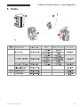
1
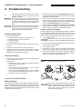
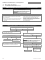
GWA
Gas-Fired Water Boilers
Control Supplement
Spark-Ignited Pilot System
Hazard definitions
Hazards that will cause severe personal injury,
death or substantial property damage.
Hazards that can cause severe personal injury,
death or substantial property damage.
Hazards that will or can cause minor personal
injury or property damage.
Special instructions on installation, operation or
maintenance that are important but not related to
personal injury or property damage.
INSTALLER — Read all instructions before
installing. Follow all instructions in proper order
to prevent personal injury or death.
• U.S. only — GWA boilers must have dampers
installed.
• Canada only — GWA boilers may have dampers
installed.
This supplement must only be used by a qualified
heating installer/service technician. Failure to
comply could result in severe personal injury, death
or substantial property damage.
Contents
Page
1 Boiler wiring ........................................................................ 2
2 Sequence of operation ........................................................ 2
3 Operating instructions ...................................................... 4-5
4 Troubleshooting ............................................................. 6-10
5 Parts ................................................................................ 11
USER — Please read the following. Failure to
comply could result in severe personal injury, death
or substantial property damage.
• Controls must only be installed and Control
Supplement used by your qualified heating
installer/service technician.
• Please see the User’s Information Manual for your
reference.
Failure to adhere to the guidelines on this page can
result in severe personal injury, death or substantial
property damage.
When calling or writing about the boiler— Please have
the boiler model number from the boiler rating label
and the CP number from the boiler jacket.
This control system is not offered for retrofit or conversion from standing pilot systems. The control system and instructions
are intended only for factory-packaged boilers. Any attempt to apply the system components to a boiler shipped for use with
a different control system will not be covered under boiler warranty and can cause severe personal injury, death or substantial
property damage.
Part Number 550-110-727/0402
2
Sequence of operation
Boiler must be electrically grounded as required by National
Electrical Code ANSI/NFPA 70-latest edition.
If rollout thermal fuse element wire as supplied with boiler must be
replaced, type 200 °C wire or equivalent must be used. If other original
wiring as supplied with boiler must be replaced, use only type 105 °C
wire or equivalent.
Wiring must be N.E.C. Class 1.
For your safety, turn off electrical power supply at service entrance
panel before making any electrical connections to avoid possible
electric shock hazard. Failure to do so can cause severe personal
injury or death.
Boiler wiring
“Operating Instructions” locations
4
5
4
Robertshaw
7200
White-Rodgers
36E or 36C
Page
Honeywell
VR8204/VR8304
GWA spark-ignited pilot — With gas valve:
Table 1
Damper must be in open position when appliance main burners are
operating. If damper is not in open position, flue products such as
carbon monoxide will escape into the house, causing severe personal
injury or death.
2. When damper is fully open, ignition control powers spark generator and opens
pilot valve.
1. See Table 1 for “Operating Instructions” page number locations. Raise room
thermostat to call for heat. Damper actuator will slowly open damper.
2
1
Canada — CSA C22.1 Canadian Electrical Code Part 1 and any other
national, provincial or local code requirements.
•
9. Set thermostat heat anticipator setting indicated in notes in wiring diagram. See
Figure 1 on page 3.
8. Return thermostat to normal setting.
7. Repeat Steps 1-6 several times to verify operation.
6. Boiler is now in the off cycle.
5. Thermostat is satisfied — pilot and main gas valves are closed. Damper will
close.
b. If power is interrupted, the control system shuts off pilot and main gas valves
and restarts at Step 1 when power is restored.
a. Ignition control monitors pilot flame current. If signal is lost, main valve is
closed, spark generator activated and sequence returns to Step 3.
4. During main burner operation:
If pilot and ignition control senses flame current — Main valve opens and
spark generator is turned off.
3. If pilot does not light within 15 seconds — Pilot valve is closed and spark
generator is turned off. The ignition control initiates a five-minute wait period. If
call for heat exists after five minutes, ignition sequence starts at Step 2.
U.S.A. — National Electrical Code and any other national, state or local
code requirements.
•
2. See wiring diagram on page 3. All wiring must be installed in accordance with:
1. Bring supply wiring to boiler. Must be 14 gauge or heavier.
GWA Gas-Fired Water Boilers – Control Supplement
Part Number 550-110-727/0402
Figure 1
Wiring diagram — Spark-ignited pilot system
GWA Gas-Fired Water Boilers – Control Supplement
Part Number 550-110-727/0402
3
GWA Gas-Fired Water Boilers – Control Supplement
3
Operating instructions
Gas valve — Honeywell VR8204 or VR8304 — White-Rodgers 36C or 36E
FOR YOUR SAFETY READ BEFORE OPERATING
If you do not follow these instructions exactly, a fire or explosion may result causing
property damage, personal injury or loss of life.
A. This appliance is equipped with an ignition
device which automatically lights the pilot. Do
not try to light the pilot by hand.
B. Before OPERATING, smell all around the
appliance area for gas. Be sure to smell next to
the floor because some gas is heavier than air
and will settle on the floor. See below.
C. Use only your hand to depress or move the selector arm. Never use tools.
If the selector arm will not depress or move by hand, don't try to repair it, call
a qualified service technician. Force or attempted repair may result in a fire
or explosion.
D. Do not use this appliance if any part has been under water. Immediately call
a qualified service technician to inspect the appliance and to replace any
part of the control system and any gas control, which has been under water.
WHAT TO DO IF YOU SMELL GAS
•
•
Do not try to light any appliance.
Do not touch any electric switch; do not use any phone in
your building.
•
•
Immediately call your gas supplier from a neighbor’s phone.
Follow the gas supplier’s instructions.
If you cannot reach your gas supplier, call the fire department.
OPERATING INSTRUCTIONS
1. Stop! Read the safety information above on this label. Vent damper operations below
apply only to GWA boilers. Find vent damper manufacturer and model on vent damper
nameplate.
2. Set the thermostat to lowest setting.
3. When equipped with Effikal vent damper Model RVGP, place service switch in Hold
Damper Open position.
4. Turn off all electrical power to the appliance.
5. When equipped with Johnson Controls vent damper Model M35, manually rotate damper
blade in direction of arrow to Open position indicated on damper assembly.
6. This appliance is equipped with an ignition device which automatically lights the pilot. Do
not try to light the pilot by hand.
to OFF. (Press down on White-Rodgers 36C valve
7. Turn gas control knob clockwise
knob to turn.)
8. When equipped with vent damper, verify damper blade is in full open position.
9. Wait five (5) minutes to clear out any gas. Then smell for gas, including near the floor. If you
smell gas, STOP! Follow “B” in the safety information above. If you don’t smell gas, go to
the next step.
to ON. (Press down on White-Rodgers 36C
10. Turn gas control knob counterclockwise
valve knob to turn.)
11. Turn on all electric power to the appliance.
12. When equipped with Effikal vent damper, place service switch in Automatic Operation
position.
13. Set thermostat to desired setting.
14. If the appliance will not operate, follow the instructions To Turn Off Gas To The Appliance
and call your service technician or gas supplier.
15. Replace front panel.
TO TURN OFF GAS TO THE APPLIANCE
1. Set the thermostat to lowest setting.
2. Turn off all electric power to the appliance if service is to
be performed.
3. Remove front panel.
4
to OFF. Do not
4. Turn gas control knob clockwise
force. (Press down on 36C valve knob to turn.)
5. Replace front panel.
Part Number 550-110-727/0402
GWA Gas-Fired Water Boilers – Control Supplement
3
Operating instructions
continued
Gas valve — Robertshaw 7200
FOR YOUR SAFETY READ BEFORE OPERATING
If you do not follow these instructions exactly, a fire or explosion may result causing
property damage, personal injury or loss of life.
A. This appliance is equipped with an ignition
device which automatically lights the pilot. Do
not try to light the pilot by hand.
B. Before OPERATING, smell all around the
appliance area for gas. Be sure to smell next to
the floor because some gas is heavier than air
and will settle on the floor. See below.
C. Use only your hand to depress or move the selector arm. Never use tools.
If the selector arm will not depress or move by hand, don't try to repair it, call
a qualified service technician. Force or attempted repair may result in a fire
or explosion.
D. Do not use this appliance if any part has been under water. Immediately call
a qualified service technician to inspect the appliance and to replace any
part of the control system and any gas control, which has been under water.
WHAT TO DO IF YOU SMELL GAS
•
•
Do not try to light any appliance.
Do not touch any electric switch; do not use any phone in
your building.
•
•
Immediately call your gas supplier from a neighbor’s phone.
Follow the gas supplier’s instructions.
If you cannot reach your gas supplier, call the fire department.
OPERATING INSTRUCTIONS
1. Stop! Read the safety information above on this label.
2. Set the thermostat to lowest setting.
7. Depress and move selector arm to OFF. Note: Selector
arm cannot be moved to OFF unless selector arm is
depressed slightly. Do not force.
3. When equipped with Effikal vent damper Model RVGP, place
service switch in Hold Damper Open position.
8. When equipped with vent damper, verify damper blade is in
full open position.
4. Turn off all electrical power to the appliance.
9. Wait five (5) minutes to clear out any gas. Then smell for
gas, including near the floor. If you smell gas, STOP! Follow
"B" in the safety information above. If you don't smell gas,
go to the next step.
5. When equipped with Johnson Controls vent damper Model
M35, manually rotate damper blade in direction of arrow to
Open position indicated on damper assembly.
6. This appliance is equipped with an ignition device which
automatically lights the pilot. Do not try to light the pilot by
hand.
10. Move selector arm to ON.
11. Turn on all electric power to the appliance.
12. When equipped with Effikal vent damper, place service
switch in Automatic Operation position.
13. Set thermostat to desired setting.
14. If the appliance will not operate, follow the instructions To
Turn Off Gas To The Appliance and call your service
technician or gas supplier.
15. Replace front panel.
TO TURN OFF GAS TO THE APPLIANCE
1. Set the thermostat to lowest setting.
2. Turn off all electric power to the appliance if service is to be
performed.
Part Number 550-110-727/0402
3. Remove front panel.
4. Depress and move selector arm to OFF. Do not force.
5. Replace front panel.
5
GWA Gas-Fired Water Boilers – Control Supplement
4
Troubleshooting
Label all wires prior to disconnection when servicing
controls. Wiring errors can cause improper and
dangerous operation.
Never jumper (bypass) rollout thermal fuse element
or any other device except for momentary testing as
outlined in “Troubleshooting” charts. Severe personal
injury, death or substantial property damage can
result.
Burner access panel must be in position during boiler
operation to prevent momentary flame rollout on
ignition of main flame. Severe personal injury or
substantial property damage will result.
Before troubleshooting:
1. Have the following items:
a. Voltmeter that can check 120 VAC and 24 VAC.
b. Microammeter with a scale range of 0-10.
c. Continuity checker.
d. U-tube manometer.
2. Check for 120 VAC (minimum 102 VAC to maximum 132 VAC)
to boiler.
3. Check for 24 VAC at secondary side of transformer.
4. Make sure thermostat is calling for heat and contacts (including
appropriate zone controls) are closed. Check for 24 VAC
between thermostat wire nuts and ground.
1. Move damper service switch to Hold Damper Open position.
Apply call for heat to boiler. Damper blade should then rotate to
open position and boiler will fire.
2. If step 1 does not open damper, manually rotate damper blade
to open position using wrench or pliers on flat shaft between
damper and actuator. Boiler will fire. Verify that damper service
switch is in Hold Damper Open position. (Figure 2)
3. Do not leave vent damper permanently in this position.
Replace actuator immediately. If vent damper is left in open
position, boiler will not operate at published efficiencies.
Johnson Controls vent damper
If troubleshooting chart recommends replacing actuator and actuator
is not immediately available, damper blade can be fixed in an open
position to allow boiler operation. Follow these instructions only in
case of no heat or damper actuator malfunction. See Figure 2.
1. Turn off power to boiler.
Failure to turn off power to boiler can result in severe
personal injury, death or substantial property damage.
2. See vent damper manufacturer’s instructions for procedure to
fix vent damper in open position.
3. Turn on power to boiler.
4. Using wrench or pliers on flat shaft section, manually rotate
damper blade until green light turns on. Boiler will fire. (Figure 2)
5. Do not leave vent damper permanently in this position. Replace
actuator immediately. If vent damper is left in open position,
boiler will not operate at published efficiencies.
Check the following:
1. Wire connectors to control module are securely plugged in at
module and originating control.
2. Gas pressures:
a. With boiler off — 13" w.c. maximum natural or propane gas
pressure upstream of gas valve.
b. With boiler on:
• 5" w.c. minimum natural gas pressure or 11" w.c. propane
gas pressure upstream of gas valve.
• 3.5" w.c. minimum natural gas pressure or 10" w.c. propane
gas pressure downstream tapping on gas valve — Can be
adjusted by regulator on gas valve.
Figure 2
Manually opening vent damper
In event of vent damper failure:
Effikal vent damper
If troubleshooting chart recommends replacing actuator and actuator
is not immediately available, damper blade can be fixed in an open
position to allow boiler operation. Manually turning blade can cause
actuator damage. Follow these instructions only in case of no heat
or damper actuator malfunction.
6
Verify proper operation after servicing. • See vent
damper manufacturer’s instructions packed with vent
damper for additional information. Failure to comply
could result in severe personal injury, death or
substantial property damage.
Part Number 550-110-727/0402
GWA Gas-Fired Water Boilers – Control Supplement
4
Troubleshooting
continued
CHART 1: No spark — System (boiler without vent damper) does not work
VISUALLY CHECK —
Is ground wire connected from GND (Burner) to ignition
control mounting screw, and ground wire connected from
transformer terminal C to case ground?
Correct by making connections.
Check for open thermostat, circulator relay(where used),
loose wire connections, defective spill switch or rollout
thermal fuse element, open LWCO or limit contacts.
DANGER
If LWCO, spill switch or rollout thermal fuse
element contacts are open, determine
cause and correct condition. Failure to do
so will cause severe personal injury, death
or substantial property damage.
Replace ignition control. Retest.
No
Yes
Is 24 VAC present across terminals 24V and 24V(GND)?
No
Yes Yes
Open thermostat contacts for 15 seconds. Close
thermostat contacts.
Is 24 VAC across terminals PV & MV/PV?
No
Yes
Turn OFF supply voltage.
Electrical shock hazard. Failure to turn off
power before proceeding could cause
severe personal injury or death.
Securely connect spark wire. Then turn ON supply voltage.
Retest.
Check spark wire.
Is it securely connected to spark transformer?
No
Yes
Is condition of spark wire good (not cut, brittle, burned or
cracked)?
Replace pilot assembly. Retest.
No
Yes
Is spark electrode ceramic cracked?
Is spark gap 0.125" and isolated in pilot gas stream?
No
Yes
Replace pilot assembly, turn ON
supply voltage. Operate system
several complete heat cycles.
Part Number 550-110-727/0402
Replace ignition
control. Retest.
No
Yes
Replace pilot assembly, turn ON supply voltage, operate
system several complete heat cycles.
7
GWA Gas-Fired Water Boilers – Control Supplement
4
Troubleshooting
continued
CHART 2: No spark — System (boiler with vent damper) does not work
Is damper harness securely plugged in at both ends?
Secure connections.
No
Check for loose wire connections or bad relay on
transformer.
Check for open thermostat, circulator relay (where used),
loose wire connections, defective spill switch or rollout
thermal fuse element, open LWCO or high limit contacts.
DANGER
If LWCO, spill switch or rollout thermal fuse
element contacts are open, determine cause
and correct condition. Failure to do so will
cause severe personal injury, death or
substantial property damage.
Check for out of round stack section.
Does motor rotate open?
No
Yes
Is 24 VAC present across transformer terminals C & Y?
No
Yes
Is 24 VAC present across terminal C and yellow wire on
between damper connector and rollout thermal fuse
element?
No
Yes
Is damper rotated open?
No
Yes
Is 24 VAC present across terminals PV and MV/PV?
Yes
No
Yes
Is spark present now?
Replace actuator. Retest.
No
Open thermostat contacts for 30 seconds. Damper will
rotate to closed position. Close thermostat contacts.
Damper will rotate to open position.
Is 24 VAC present across terminals PV and MV/PV?
No
Retest.
Turn OFF supply voltage.
Electrical shock hazard. Failure to turn off
power before proceeding could cause
severe personal injury or death.
Yes
Check continuity of each wire in wiring harness to damper.
Does continuity exist for each wire?
No
Yes
Securely connect and
turn ON supply
voltage. Retest.
Check spark wire.
Is it securely connected to
ignition control?
Yes
Replace damper wiring
harness. Retest.
Replace ignition
control. Retest.
Remove damper harness from
boiler wiring harness.
TEMPORARILY install jumper
between terminal 2 and
terminal 5 on damper plug in
boiler wiring harness. See
figure below. Does boiler fire?
No
1
2
3
4
5
6
No
Replace pilot
assembly.
Retest.
Yes
Is spark electrode
ceramic cracked?
No
Yes
Yes
Replace pilot
assembly.
Temporary
jumper
Is condition of spark wire good (not
brittle, burned or cracked)?
No
Yes
Is spark gap 0.125" and
located in pilot gas stream?
No
Yes
Replace damper
actuator. Retest.
Replace ignition
control. Retest.
Replace pilot
assembly.
Turn ON supply voltage and
operate system several complete
cycles.
Remove jumper after test.
Failure to remove jumper
could result in severe
personal injury or death.
8
Part Number 550-110-727/0402
GWA Gas-Fired Water Boilers – Control Supplement
4
Troubleshooting
continued
CHART 3: Pilot lights — Main valve will not come on (boiler with or without damper)
Does spark stay on for more than a few seconds after pilot is established?
No
Yes
Turn OFF supply voltage.
Is 24 VAC between terminals MV and MV/PV on
ignition control?
No
Electrical shock hazard. Failure to turn off
power before proceeding could cause severe
personal injury or death.
Yes
Replace ignition control.
Retest.
Make sure sense wire is not wrapped around any pipe or
accessories.
Is inlet gas pressure at least 5.0" w.c. and not over
13" w.c.?
No
Is sense wire securely attached to sense terminal
and pilot assembly?
Yes
No
Yes
Correct and retest.
Contact gas supplier to
correct.
Is sensing probe ceramic cracked?
No
Is main valve wiring secure at terminals?
No
Yes
Correct wiring. Retest.
Replace valve. Retest.
Replace pilot assembly.
Retest.
Is sense wire or sensing probe shorted out to metal
surface?
No
Check for continuity of sense wire and condition of
insulation.
NOT OK
Replace pilot assembly.
Retest.
Replace ignition control.
Retest.
Yes
Yes
Correct and retest.
OK
Does system have proper flame signal?
Set up microammeter to measure output current in flame sensor circuit as follows.
a. Detach sense lead from ignition control. Attach negative lead from microammeter to
sense terminal on ignition control.
b. Attach positive lead to sense wire from pilot assembly.
c. Disconnect main valve lead from terminal MV on ignition control.
d. Energize the system. Spark should ignite the pilot. As soon as pilot is burning,
microammeter should read at least 0.5 microamp for Honeywell S8620C, 0.1 microamp
for U.T. 1003-510
e. Is flame current signal less than the minimum specified in d above?
No
Yes
Check for proper gas pressure, clean pilot assembly, tight mechanical and electrical
connections. Also check for proper system grounding per following page.
Part Number 550-110-727/0402
9
GWA Gas-Fired Water Boilers – Control Supplement
4
Troubleshooting
continued
CHART 3: Pilot lights — Main valve will not come on — continued from previous page
Turn OFF supply voltage.
Electrical shock hazard. Failure to turn off
power before proceeding could cause
severe personal injury or death.
To check ignition system grounding (instruction for continuation of Chart 3)
Pilot assembly and ignition control must share common ground
with main burner. Nuisance shutdowns are often caused by
poor or erratic ground.
❏ Check for good metal-to-metal contact between pilot burner
bracket and main burner, and between main burner and
burner rest.
❏ Check ground lead from GND (Burner) terminal on ignition
control to ignition control mounting screw and from C on
transformer to transformer case ground. Make sure
connections are clean and tight. If wire is damaged or
deteriorated, replace with No. 18 gauge moisture-resistant,
thermoplastic insulated wire with
105 ˚C minimum rating.
CHART 4: Spark is present — Pilot will not light (boiler with or without damper)
Are pilot valve wiring connections CORRECT and securely fastened?
No
Connect securely to terminal PV on ignition control and
terminal TR on main gas valve.
Is pilot shutoff valve open?
No
Yes
Open pilot shutoff valve.
Contact gas supplier to
correct gas pressure.
Make sure pilot shutoff valve is open, 24 VAC is present to
pilot valve and pilot line is not kinked or obstructed. Check
for clean pilot orifice. If OK, replace pilot gas valve.
Yes
Is inlet gas pressure at least 5.0" w.c. and not over
14" w.c.?
No
Is gas present at pilot burner assembly?
Remove MV wire from ignition control. Use a
match taped to a long screwdriver or pilot
lighter rod and manually light pilot.
No
Yes
Is spark gap 0.125" and located in pilot gas stream?
No
Replace pilot assembly.
10
Yes
Yes
Block any draft around
boiler. Check for clean
pilot orifice.
Part Number 550-110-727/0402
GWA Gas-Fired Water Boilers – Control Supplement
5
Parts
Part Number 550-110-727/0402
11
GWA Gas-Fired Water Boilers – Control Supplement
W-T
8201 W. Calumet Rd.
Milwaukee, WI 53223
12
Part Number 550-110-727/0402