1
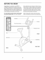
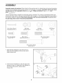
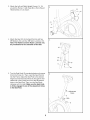
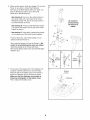
®
W
Sears Model No, 831,21600,1
Kmart Model No. WLEX1076.1
USER'S MANUAL
Serial No,
Write the serial number in the
space above for future reference.
Serial Number
Decal
QUESTIONS?
As a manufacturer, we are committed to providing complete
customer satisfaction. If you have
questions, PLEASE CONTACT
OUR CUSTOMER SERVICE
DEPARTMENT DIRECTLY.
SEARS CUSTOMERS:
1-800-4-MY-HOME ®
(1-800-469-4663)
KMART CUSTOMERS:
1-866-699-3756
Mon.-Fri., 6 a.m.-6 p.m. MST
_CAUTION
Read all precautions and instructions in this manual before using
this equipment. Keep this manual
for future reference.
www.weslo.com
new products, prizes,
fitness tips, and much more!
TABLE OF CONTENTS
IMPORTANT PRECAUTIONS
................................................................
BEFORE YOU BEGIN ......................................................................
ASSEMBLY ...............................................................................
HOW TO OPERATE THE EXERCISE CYCLE ....................................................
MAINTENANCE AND TROUBLESHOOTING
...................................................
CONDITIONING GUIDELINES ...............................................................
PART LIST ..............................................................................
EXPLODED DRAWING ....................................................................
ORDERING REPLACEMENT PARTS ..................................................
LIMITED WARRANTY ..............................................................
2
3
4
8
10
11
14
15
Back Cover
Back Cover
IMPORTANT PRECAUTIONS
_WARNING:
To reduce the risk of serious injury, read the following important precau-
tions before using the exercise cycle.
1. Read all instructions in this manual and all
warning decals on the exercise cycle before
using the exercise cycle. Use the exercise
cycle only as described in this manual.
2. It is the responsibility of the owner to ensure
that all users of the exercise cycle are adequately informed of all precautions.
The exercise cycle is intended for home use
only. Do not use the exercise cycle in
a commercial, rental, or institutic hal setting.
4.
Use the exercise cycle indoors on a level surface. Keep the exercise cycle away from
moisture and dust. Place a mat under the
exercise cycle to protect the floor. Make sure
that there is enough clearance around the
exercise cycle to mount, dismount, and use
the exercise cycle,
5. Inspect and properly tighten all parts regularly.
Replace any worn parts immediately.
6. Keep children under the age of 12 and pets
away from the exercise cycle at all times,
7. Wear appropriate clothes while exercising; do
not wear loose clothes that could become
A WARN ING:
caught on the exercise cycle. Always wear
athletic shoes for foot protection.
8. The exercise cycle should not be used by
persons weighing more than 250 pounds.
9. Always keep your back straight while using
the exercise cycle; do not arch your back.
10. If you feel pain or dizziness while exercising,
stop immediately and cool down.
11. The exercise cycle does not have a free
wheel; the pedals will continue to move until
the flywheel stops.
12. The pulse sensor is not a medical device.
Various factors, including the user's movement, may affect the accuracy of heart rate
readings. The pulse sensor is intended only
as an exercise aid in determining heart rate
trends in general.
13.The warning decal shown on page 3 has been
placed on the exercise cycle. If the decal is
missing or illegible, call the toll-free telephone number on the front cover of this manual and order a free replacement decal. Apply
the decal in the location shown.
Before beginning this or any exercise program, consult your physician. This
is especially important for persons over the age of 35 or persons with pre-existing health problems.
Read all instructions before using. ICON assumes no responsibility for personal injury or property
damage sustained by or through the use of this product.
BEFORE YOU BEGIN
Congratulations for selecting the new WESLO ®
PURSUIT 350 exercise cycle. Cycling is one of the
most effective exercises for increasing cardiovascular
fitness, building endurance, and toning the body. The
PURSUIT 350 exercise cycle offers a selection of features designed to let you enjoy this healthful exercise
in the convenience and privacy of your home.
after reading this manual, please see the front cover
of this manual. To help us assist you, note the product
model number and serial number before contacting
us. The model number is found on the front cover of
this manual. The serial number is found on a decal
attached to the exercise cycle (see the front cover of
this manual for the location of the decal).
For your benefit, read this manual carefully before
you use the exercise cycle. If you have questions
Before reading further, please review the drawing
below and familiarize yourself with the labeled parts.
Handlebar
• Misuse of this machine
may result in serious
injury.
• Read user's manual
prior to use and fogow
aU warnings and
instructions,
• DO not allow children
on or around machine.
Console
Thumb Pulse Sensor
° Pedals continue to
spin when you stop
pedaling.
• Spinning pedals can
cause injury.
• Reduce pedal speed
in a contromedmanner.
User weight must not
exceed 250 pounds,
Resistance Knob
, Replace label if
damaged, illegible, or
removed,
Seat
FRONT
Seat Knob
Pedal/Strap
RIGHT SIDE
REAR
ASSEMBLY
Assembly requires two persons. Place all parts of the exercise cycle in a cleared area and remove the packing
materials. Do not dispose of the packing materials until assembly is completed. Assembly requires the included tools and your own adjustable wrench _,
Phillips screwdriver
_
_,
and
pliers _.
Use the drawings below to identify the small parts used for assembly. The number in parentheses below each
drawing is the key number of the part, from the PART LIST on page 14. The number following the key number is
the quantity needed for assembly. Note: Some small parts may have been preassembled. If a part is not in
the parts bag, check to see if it has been preassembled.
l\
M4 x 25mm Round
Head Screw (41)-3
M6 x 15mm Button
Screw (46)-4
M8 Nylon
Locknut (10)-4
M8 Washer
(54)-4
M8 Split
Washer (42)-3
M8 x 20mm
Button Screw (34)-3
M8 x 55mm Button
Screw (30)-4
MIO x 60mm Button
Screw (33)-2
1. Slide the Rear Stabilizer (6) into the Frame (1).
Attach the Rear Stabilizer with four M8 x 55mm
Button Screws (30).
i
i
6
30
2. Orient the Front Stabilizer (2) with the large holes
facing the Frame (1). Attach the Front Stabilizer to
the Frame with two M10 x 60mm Button
Screws (33).
33
Large
Holes
--.
3. Attachthe LeftandRightUprightCovers(14,15)
aroundtheFrame(1)withthreeM4x 25mmRound
HeadScrews(41)asshown.
15
1
41
14_
4. AttachtheSeat(12)to theSeatPost(5)withfour
M8Washers(54)andfourM8NylonLocknuts(10).
Note: The Washers and the Nylon Locknuts may
be pre-attached to the underside of the Seat,
54
5. Turn the Seat Knob (9) counterclockwise and remove
it from the Frame (1). Then, insert the Seat Post (5)
into the Frame. Adjust the Seat Post to the desired
height and insert the Seat Knob (9) through the indicated hole in the Frame into one of the adjustment
holes in the Seat Post. Then, turn the Seat Knob
clockwise until it is tight. Make sure the Seat Knob
is firmly engaged in one of the adjustment holes
in the Seat Post,
Adjustment
Holes
6. WhileanotherpersonholdstheUpright(13)nearthe
Frame(1)asshown,connectthe Extension
Wire(52)tothe ReedSwitchWire(43).Next,connectthe Resistance
Cable(19)totheLower
Cable(45)inthefollowing
way:
• SeedrawingA. Pullupon themetalbracketon
theLowerCable(45),andinsertthetipof the
Resistance
Cable(19)intothewireclipinsideof
themetalbracketasshown.
• SeedrawingB. Firmlypullthe Resistance
Cable
(19)upwardandslideit intothetopofthemetal
bracketasshown.
• SeedrawingC.Usingpliers,squeezetheprongs
ontheupperendofthemetalbrackettogether.
PushtheWires(52,43)andtheCables(19,45)
downward
intotheFrame(1).
Next,inserttheUpright(13)intotheFrame(1).Be
carefulto avoid pinchingthe wiresandcables.
AttachtheUprighttotheFramewiththree
M8x 20mmButtonScrews(34)andthreeM8Split
Washers(42).
A
_
B
C
i-_
Metal
_Bracket
Metal_
Bracket _
19 _,_
i
7. TheConsole(16)requiresfour"AA"batteries(not
included);
alkalinebatteriesarerecommended.
Pressthetabonthebatterycoverandremoveit.
InsertfourbatteriesintotheConsoleasshown.
45
Battery
Make sure that the batteries are oriented as
shown by the diagram on the battery cover.
Then, reattach the battery cover.
j_
8. Whilea secondpersonholdstheConsole(16)near
the Upright(13),connecttheconsolewiretothe
Extension
Wire(52).Then,insertthewiresdownwardintothe Upright.
16
AttachtheConsole(16)to theUpright(13)withfour
M6x 15mmButtonScrews(46).Becarefulto
avoid pinchingthe wires.
52
Console
Wire
46
Be careful to
avoid pinching
the wires.
9. Identifythe LeftPedal(24),whichis markedwitha
"Left"sticker.Usingan adjustable
wrench,firmly
tightentheLeftPedalcounterclockwise into the left
arm of the Crank (21). Tighten the Right Pedal (not
shown) clockwise into the right arm of the Crank.
Important: Tighten both Pedals as firmly as possible. After using the exercise cycle for one
week, retighten the Pedals. For best performance,
keep the Pedals tightened.
Adjust a Pedal Strap (53) to the desired position,
and press the end of the Pedal Strap onto the tab on
the side of the Left Pedal (24). Adjust the other
Pedal Strap (not shown) in the same way.
21
24
/
10.Make sure that all parts are properly tightened before you use the exercise cycle, Note: After assembly is
completed, some extra parts may be left over. Place a mat beneath the exercise cycle to protect the floor.
7
HOW TO OPERATE THE EXERCISE CYCLE
HOW TO ADJUST THE SEAT POST
FEATURES OF THE CONSOLE
For effective exercise, the seat
should be at the
proper height. As
Seat
you pedal, there
should be a slight
bend in your knees
Seat Post
when the pedals
are in the lowest
position. To adjust
Hole\
the height of the
seat, first turn the
Seat Knob
seat knob counterclockwise and
remove it. Next,
slide the seat post upward or downward and align one
of the adjustment holes in the seat post with the indicated hole in the Frame. Insert the seat knob into the
frame and the seat post, and turn the seat knob clockwise until it is tight. Make sure that the seat knob is
inserted through one of the adjustment holes in
the seat post,
The easy-to-use console features seven displays that
provide instant exercise feedback during your workouts. The displays are described below:
HOW TO ADJUST THE PEDALING
To increase the
resistance of the
pedals, turn the
resistance knob
clockwise; to
decrease the resistance, turn the
knob counterclockwise. Important:
Stop turning the
knob when turning becomes difficult, or damage
may result,
RPM
SPEED
TARGET
TiME
PULSE
DISTANCE
SENSOR
/
RESISTANCE
Thumb Pulse Sensor
Speed--This display shows your pedaling speed, in
miles or kilometers per hour.
Time--This
Knob
display shows the elapsed time.
Distance--This display shows the distance you have
pedaled, in miles or kilometers per hour.
Calories--This display shows the approximate number
of calories you have burned.
Fat Calories--This display shows the approximate
number of fat calories you have burned (see Burning
Fat on page 11).
Pulse--This display shows your heart rate when you
use the thumb pulse sensor.
Scan--This display shows speed, time, distance, calories, fat calories, and pulse information in a repeating
cycle. Note: The pulse display will appear only when
you use the thumb pulse sensor.
HOWTOUSE
THE CONSOLE
Note: The console can show speed and distance in either miles or kilometers, The letters
Before using the console, make sure that batteries
are installed (see assembly step 7 on page 6). If there
is a sheet of clear plastic on the display, remove the
plastic.
"mph" or "km/h" will appear in the display to show
which unit of measurement is selected. To change
the unit of measurement, hold down the On/Reset
button for several seconds until the desired unit of
measurement appears in the display.
Follow the steps below to operate the console.
To reset the display, press the On/Reset button.
B
To pause the console, stop pedaling. When the
console is paused, the time will flash in the display. To continue your workout, simply resume
pedaling.
Turn on the console.
To turn on the
SCAN
FAT CALS,
console, press
the On/Reset
button or begin
pedaling. The
entire display
RPM SPEED
TiME
will light for a
moment; the
console will then be ready for use.
CALOR|ES
uZ.Ju
la
Measure your heart rate if desired.
To measure your
heart rate, stop
pedaling and
place your
thumb on the
DISTANCE
E!
Select one of the modes.
SCANFATCALS.
CALORIES
pulse sensor. Do
RPM SPEED
TIME
DISTANCE
not press too
hard, or the circulation in your thumb will be restricted and
your pulse will not be detected, After a few seconds, the heart-shaped indicator in the display will
flash steadily, two dashes will appear, and then
your heart rate will be shown. Hold your thumb on
the pulse sensor for about 15 seconds for the
most accurate reading.
When you turn
the power on,
Indicators
the scan disTCALS.CALOR|ES
play will be
selected automatically. One
indicator will
appear below
RPMSPEED T'ME DISTANCE
the word Scan
to show that the scan display is selected, and a
second indicator will show which information is
currently displayed.
If the displayed heart rate appears to be too high
or too low, or if your heart rate is not displayed, lift
your thumb off the pulse sensor for a few seconds. Then, place your thumb on the pulse sensor
as described above.
To select
SCAN
FAT CALS.
CALORIES
speed, time,
distance, calories, or fat calories information
for continuous
RPM SPEED
TiME
DISTANCE
display, press
the Display button repeatedly. The indicators will show which
display is selected. Make sure there is not an
indicator below the word Scan.
Make sure you are applying the proper amount of
pressure to the pulse sensor. Try the pulse sensor
several times until you become familiar with it.
Remember to sit still while measuring your heart
rate.
B
hen you are finished exercising, the console will turn off automatically.
If the pedals do not move for a few seconds, the
time will flash in the display and the console will
pause, tf the pedals do not move for a few minutes, the console will turn off and the display will
be reset.
As you pedal, the RPM meter on the left side of
the display will indicate your approximate pedaling pace in revolutions per minute (rpm). The
lowest bar on the RPM meter indicates a pedaling pace of 30 rpm. Additional bars will appear or
disappear in increments of 10 rpm as you change
your pedaling pace.
9
MAINTENANCE
AND TROUBLESHOOTING
Inspect and tighten all parts of the exercise cycle regularly. Replace any worn parts immediately.
Switch slightly closer to or away from the Magnet, and
then retighten the Screw. Turn the Crank for a
moment. Repeat until the console displays correct
feedback. When the Reed Switch is correctly adjusted, reattach the left side shield, the upright covers,
and the left pedal.
To clean the exercise cycle, use a damp cloth and a
small amount of mild detergent. Important: To avoid
damage to the console, keep liquids away from
the console and keep the console out of direct
sunlight.
HOW TO ADJUST THE BELT
BATTERY REPLACEMENT
If you can feel the pedals slip while you are pedaling,
even when the resistance is at the highest level, the
belt may need to be adjusted. See HOW TO ADJUST
THE REED SWITCH at the left and remove the left
pedal, the upright covers, and the left side shield.
If the console display becomes dim, the batteries
should be replaced; most console problems are the
result of low batteries. To replace the batteries, see
assembly step 7 on page 6.
To adjust the belt, you must also remove the right
pedal and the right side shield. Using an adjustable
wrench, turn the right pedal counterclockwise and
remove it. Then, remove the screws from the right
side shield. Note: One screw from the side shield is
shorter than the other screws. Make sure to note the
correct location of the short screw. Then, carefully
remove the right side shield.
HOW TO ADJUST THE REED SWITCH
If the console does not display correct feedback, the
reed switch should be adjusted. To adjust the reed
switch, the left pedal, the upright covers, and the left
side shield must be removed.
Using an adjustable wrench, turn the left pedal clockwise and remove it. Next, remove the screws from the
upright covers and the left side shield. Note: One
screw from the side shield is shorter than the other
screws. Make sure to note the correct location of the
short screw. Then, carefully remove the upright covers
and the left side shield.
Next, loosen, but do not remove, the M8 x 20mm
Bolt (23). Loosen the two M8 Nylon Locknuts (10),
one on each side of the Flywheel (37). Tighten the M6
Nylon Locknuts (32), one on each side of the
Flywheel, until the Belt (35) is properly tightened.
Then, tighten the M8 Nylon Locknuts (10) and the M8
x 20mm Bolt (23). Finally, reattach the side shields,
the upright covers, and the pedals.
Next, turn the resistance knob to the lowest setting.
With the left side shield removed, locate the Reed
Switch (43). Turn the Crank (21) until the Magnet (38)
is aligned with the Reed Switch. Loosen, but do not
remove, the M4 x 15mm Screw (47). Slide the Reed
10
CONDITIONING
GUIDELINES
The following guidelines will help you to plan your
exercise program. Remember that proper nutrition
and adequate rest are essential for successful results.
During the first few minutes of exercise, your body
uses easily accessible carbohydrate calories for energy. Only after the first few minutes of exercise does
your body begin to use stored fat calories for energy.
If your goal is to burn fat, adjust the intensity of your
exercise until your heart rate is near the lowest number in your training zone as you exercise. For maximum fat burning, adjust the intensity of your exercise
until your heart rate is near the middle number in your
training zone as you exercise.
WARNING: Before
beginning
this or any exercise program, consult your
physician. This is especially important for
persons over the age of 35 or persons with
pre-existing health problems.
Aerobic Exercise
The pulse sensc r is not a medical device.
Various factors may affect the accuracy of
heart rate readings. The pulse sensor is
intended only as an exercise aid in determining heart rate trends in general.
If your goal is to strengthen your cardiovascular system, your exercise must be "aerobic." Aerobic exercise is activity that requires large amounts of oxygen
for prolonged periods of time. This increases the
demand on the heart to pump blood to the muscles,
and on the lungs to oxygenate the blood. For aerobic
exercise, adjust the intensity of your exercise until
your heart rate is near the highest number in your
training zone.
EXERCISE INTENSITY
Whether your goal is to burn fat or to strengthen your
cardiovascular system, the key to achieving the
desired results is to exercise with the proper intensity.
The proper intensity level can be found by using your
heart rate as a guide. The chart below shows recommended heart rates for fat burning, maximum fat
burning, and cardiovascular (aerobic) exercise.
165 155 145
140 130 125
115
145 138 130
125
118 110
103
125 120 115 110 105 95
90
20
80
30
40
50
60
70
WORKOUT
GUIDELINES
Each workout should include the following three parts:
A warm-up, consisting of 5 to 10 minutes of stretching
and light exercise. A proper warm-up increases your
body temperature, heart rate, and circulation in preparation for exercise.
_
Training zone exercise, consisting of 20 to 30 minutes of exercising with your heart rate in your training
zone. (During the first few weeks of your exercise program, do not keep your heart rate in your training
zone for longer than 20 minutes.)
_)
A cool-down, with 5 to 10 minutes of stretching (see
page 12). This will increase the flexibility of your muscles and will help to prevent post-exercise problems.
To find the proper heart rate for you, first find your age
at the bottom of the chart (ages are rounded off to the
nearest ten years). Next, find the three numbers above
your age. The three numbers are your "training zone."
The lowest number is the recommended heart rate for
fat burning, the middle number is the recommended
heart rate for maximum fat burning, and the highest
number is the recommended heart rate for aerobic
exercise.
EXERClSEFREQUENCY
To maintain or improve your condition, plan three workouts each week, with at least one day of rest between
workouts. After a few months of regular exercise, you
may complete up to five workouts each week, if
desired. Remember, the key to success is make exercise a regular and enjoyable part of your everyday life.
Burning Fat
To burn fat effectively, you must exercise at a relatively low intensity level for a sustained period of time.
11
SUGGESTED
STRETCHES
The correct form for several basic stretches is shown at the right.
Move slowly as you stretch--never bounce.
1. Toe Touch Stretch
Stand with your knees bent slightly and slowly bend forward from
your hips. Allow your back and shoulders to relax as you reach
down toward your toes as far as possible. Hold for 15 counts, then
relax. Repeat 3 times. Stretches: Hamstrings, back of knees and
back.
2. Hamstring Stretch
Sit with one leg extended. Bring the sole of the opposite foot
toward you and rest it against the inner thigh of your extended leg.
Reach toward your toes as far as possible. Hold for 15 counts,
then relax. Repeat 3 times for each leg. Stretches: Hamstrings,
lower back and groin.
3. Calf/Achilles Stretch
With one leg in front of the other, reach forward and place your
hands against a wall. Keep your back leg straight and your back
foot flat on the floor. Bend your front leg, lean forward and move
your hips toward the wall. Hold for 15 counts, then relax. Repeat 3
times for each leg. To cause further stretching of the achilles tendons, bend your back leg as well. Stretches: Calves, achilles tendons and ankles.
4. Quadriceps Stretch
With one hand against a wall for balance, reach back and grasp
one foot with your other hand. Bring your heel as close to your buttocks as possible. Hold for 15 counts, then relax. Repeat 3 times
for each leg. Stretches: Quadriceps and hip muscles.
5. Inner Thigh Stretch
Sit with the soles of your feet together and your knees outward.
Pull your feet toward your groin area as far as possible. Hold for 15
counts, then relax. Repeat 3 times. Stretches: Quadriceps and hip
muscles.
12
NOTES
13
PART LIST
Key No. Qty,
1
2
3
4
5
6
7
8
9
10
11
12
13
14
15
16
17
18
19
20
21
22
23
24
25
26
27
28
29
1
1
1
2
1
1
2
2
1
7
1
1
1
1
1
1
1
1
1
1
1
1
1
1
2
1
1
2
1
SEARS MODEL NO. 831.21600.1; KMART MODEL NO. WLEX1076.1
Description
Key No. Qty,
Frame
Front Stabilizer
Left Side Shield Cover
Front Stabilizer Endcap
Seat Post
Rear Stabilizer
Handlebar Endcap
Rear Stabilizer Endcap
Seat Knob
M8 Nylon Locknut
C-Magnet
Seat
Upright
Left Upright Cover
Right Upright Cover
Console
Left Side Shield
Right Side Shield
Resistance Control/Cable
Seat Post Bushing
Crank/Pulley
Reed Switch Clamp
M8 x 20mm Bolt
Left Pedal
6200Z Bearing
Right Pedal
Resistance Knob
U-bracket
M6 Nut
30
31
32
33
34
35
36
37
38
39
40
41
42
43
44
45
46
47
48
49
50
51
52
53
54
55
#
#
4
2
2
2
3
1
1
1
1
1
2
8
3
1
1
1
4
3
1
1
1
1
1
2
4
1
1
2
R0706A
Description
M8 x 55mm Button Screw
Eyebolt
M6 Nylon Locknut
M10 x 60mm Button Screw
M8 x 20mm Button Screw
Belt
Right Side Shield Cover
Flywheel
Magnet
Flywheel Axle
M10 Small Washer
M4 x 25mm Round Head Screw
M8 Split Washer
Reed Switch/Wire
Crank Bearing Set
Lower Cable
M6 x 15mm Button Screw
M4 x 15mm Screw
Spring
M5 x 35mm Button Screw
M5 Curved Washer
M6 x 40mm Bolt
Extension Wire
Pedal Strap
M8 Washer
Bracket
User's Manual
Hex Key
Note: "#" indicates a non-illustrated part. Specifications are subject to change without notice. See the back cover
of this manual for information about ordering replacement parts.
14
EXPLODED DRAWING
SEARS MODEL NO. 831.21600.1; KMART MODEL NO. WLEX1076.1
7--_
36
53
38
42
>34
10
20 _
52
44
39
37
43
32
25
55
10
31
32
47
6
30
RO706A
15
ORDERING
REPLACEMENT
PARTS
To order replacement parts, please see the front cover of this manual. To help us assist you, be prepared to
provide the following information when contacting us:
• the MODEL NUMBER of the product (Sears Model No. 831.21600.1;
Kmart Model No. WLEX1076.1)
• the NAME of the product (WESLO PURSUIT 350 exercise cycle)
• the SERIAL NUMBER of the product (see the front cover of this manual)
• the KEY NUMBER and DESCRIPTION of the part(s) (see the PART LIST on page 14)
WESLO is a registered trademark of ICON IP, Inc.
LIMITED WARRANTY
ICON Health & Fitness, Inc. (ICON) warrants this product to be free from defects in workmanship and
material, under normal use and service conditions, for a period of ninety (90) days from the date of purchase. This warranty extends only to the original purchaser. ICON's obligation under this warranty is limited to replacing or repairing, at ICON's option, the product through one of its authorized service centers.
All repairs for which warranty claims are made must be pre-authorized by ICON. If the product is shipped
to a service center, freight charges to and from the service center will be the customer's responsibility. For
in-home service, the customer will be responsible for a minimal trip charge. This warranty does not extend
to any product or damage to a product caused by or attributable to freight damage, abuse, misuse,
improper or abnormal usage or repairs not provided by an ICON authorized service center; products used
for commercial or rental purposes; or products used as store display models. No other warranty beyond
that specifically set forth above is authorized by ICON.
ICON is not responsible or liable for indirect, special or consequential damages arising out of or in connection with the use or performance of the product or damages with respect to any economic loss, loss
of property, loss of revenues or profits, loss of enjoyment or use, costs of removal or installation or other
consequential damages of whatsoever nature. Some states do not allow the exclusion or limitation of incidental or consequential damages. Accordingly, the above limitation may not apply to you.
The warranty extended hereunder is in lieu of any and all other warranties and any implied warranties of
merchantability or fitness for a particular purpose is limited in its scope and duration to the terms set forth
herein. Some states do not allow limitations on how long an implied warranty lasts. Accordingly, the above
limitation may not apply to you.
This warranty gives you specific legal rights. You may also have other rights which vary from state to state.
ICON HEALTH & FITNESS, INC., 1500 S. 1000 W., LOGAN, UT 84321-9813
Part No. 244021 RO706A
Printed in China © 2006 ICON IP, Inc.