1
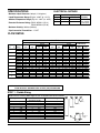
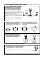
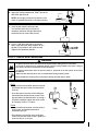
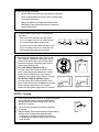
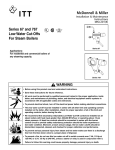
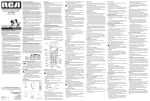
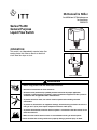
McDonnell & Miller
Installation & Maintenance
Instructions
MM-625
Series FS-250
General Purpose
Liquid Flow Switch
OPERATION
Model FS251-NEMA1
This control is an independently mounted water flow
sensing device that makes or breaks an electrical
circuit when flow stops or starts.
FLOW
Model FS254-NEMA4
! WARNING
CAUT
WARN
ING
ION
• Before using product, read and understand instructions.
• Save these instructions for future reference.
• All work must be performed by qualified personnel trained in the proper application,
installation, and maintenance of plumbing, steam and electrical equipment and/or systems in
accordance with all applicable codes and ordinances.
• To prevent electrical shock, turn off the electrical power before making electrical
connections.
• To prevent an electrical fire or equipment damage, electrical wiring insulation must have a
rating of 167˚F (75˚C) if the liquid’s temperature exceeds 180˚F (82˚C).
• To prevent electrocution, when the electrical power is connected to the flow switch, do not
touch the terminals.
• Make sure flow switch electrical cover is secured before turning on electric power.
Failure to follow this warning could cause property damage, personal injury or death.
SPECIFICATIONS
ELECTRICAL RATINGS
Maximum Liquid Pressure: 160 psi (11.3 kg/cm2)
Liquid Temperature Range (TL): 32 - 250˚F (0 - 121˚C)
Motor Switch Rating (Amperes)
Full Load Locked Rotor
Pilot Duty
7.4
44.4
125 VA at
120 or 240 VAC
3.7
22.2
50 or 60 cycles
Voltage
120 VAC
240 VAC
Ambient Temperature Range (TS): 32 - 120˚F (0 - 49˚C)
Electrical Enclosure Rating: FS251: NEMA 1 (IP 21)
FS254: NEMA 4 (IP 56)
Maximum Velocity: 10ft/sec (3M/sec)
Pipe Connection Thread Size: - 1" NPT
FLOW RATES
Series FS250
FLOW
Pipe Size
NPT
in.
1"
1-1/4"
1-1/2"
2"
2- 1/2"
3"
4"
5"
6"
NO FLOW
Velocity
Settings
Minimum
Maximum
Minimum
Maximum
Minimum
Maximum
Minimum
Maximum
Minimum
Maximum
Minimum
Maximum
Minimum
Maximum
Minimum
Maximum
Minimum
Maximum
Max. Flow Rate w/o
Paddle Damage
Velocity
gpm
lpm
fps
mps
gpm
lpm
fps
mps
gpm
lpm
5.8
12.6
6.7
19.1
8.4
25.3
12.9
31.5
17.9
43.2
26.2
54.9
42.0
75.6
54.6
109.4
67.7
131.1
22
48
25
72
32
96
49
119
68
164
99
208
159
286
207
414
256
496
2.15
4.67
1.43
4.07
1.32
3.97
1.24
3.02
1.20
2.89
1.13
2.36
1.05
1.89
0.87
1.75
0.75
1.44
0.66
1.42
0.43
1.24
0.40
1.21
0.38
0.92
0.37
0.88
0.34
0.72
0.32
0.58
0.27
0.53
0.23
0.44
5.1
11.9
6.0
18.0
7.0
24.1
11.2
30.2
14.5
40.0
20.2
49.8
33.7
68.0
46.7
98.4
60.2
123.5
19
45
23
68
26
91
42
114
55
151
76
188
128
257
177
372
228
467
1.89
4.41
1.28
3.83
1.10
3.78
1.08
2.90
0.97
2.68
0.87
2.14
0.84
1.70
0.75
1.57
0.66
1.36
0.58
1.35
0.39
1.17
0.33
1.15
0.33
0.88
0.30
0.82
0.26
0.65
0.26
0.52
0.23
0.48
0.20
0.41
27
102
47
178
63
242
105
397
149
564
230
871
397
1503
654
2475
900
3407
NOTE: DO NOT USE LIQUID FLOW SWITCHES ON SYSTEMS WITH
FLOW VELOCITY GREATER THAN 10 FEET (3M) PER SECOND.
STEP 1 - Paddle Sizing
Determine the correct paddle length for your installation from the chart below.
Pipe Size
in.
1
1-1/4
1-1/2
2
2-1/2
3
4
6
8+
(mm)
(25)
(32)
(40)
(50)
(65)
(80)
(100)
(150)
(200+)
Paddle
(Standard Length)
in.
(mm)
1
(25)
2
(51)
2
(51)
2
(51)
3
(76)
3
(76)
6
(152)
6
(152)
6
(152)
NOTE: All models include 4 paddles as shown.
2
Trim to Length
in.
1" (25mm)
(mm)
N/A
1-1/4
1-1/2
2" (51mm)
(32)
(38)
3" (76mm)
N/A
2-1/4
(57)
N/A
3-5/8
A
(92)
N/A
N/A
6" (152mm)
B
Required
Length
STEP 2 - Determine the Location of the Flow Switch
• The flow switch should be located in a horizontal
section of pipe where there is a straight horizontal
run of at least 5 pipe diameters on each side of the
flow switch. The flow switch may be installed in a
vertical pipe if the flow is in the upward direction.
1" PIPE
CONNECTION
• The flow switch must be installed in the upright
position as shown with arrow mark on side of casting
in the same direction as fluid will flow.
FLUID FLOW
• Some system conditions that require more than 5 pipe
diameters are high viscosity fluid and high fluid velocity.
5xD
MINIMUM
D
5xD
MINIMUM
D= PIPE DIAMETER
• The flow switch must be installed in the pump suction
piping when spring-loaded check valves and/or other
close coupled accessories are installed in the pump
discharge piping.
a. The flow switch must be installed in the pipe using
a threaded tee connection or welding fitting of
minimum length such as a half coupling. Use a
face or hex bushing to reduce the tee outlet to 1”
pipe thread if a reduced tee outlet thread size fitting
is not available.
1" (25mm)
FACE OR HEX.
BUSHING
1" (25mm)
1" (25mm)
1"
(25mm)
1"
(25mm)
Threaded
Pipe
11/4"
(32mm)
11/2"
(40mm)
2"
(50mm)
11/4"
(32mm)
11/2"
(40mm)
2"
(50mm)
11/4" (32mm)
11/2" (40mm)
2" (50mm)
21/2" (65mm)
3" (80mm)
Threaded
Pipe
11/4" (32mm)
11/2" (40mm)
2" (50mm)
21/2" (65mm)
3" (80mm)
2" (50mm)
21/2" (65mm)
3" (80mm)
4" (100mm)
6" (150mm)
1" MAX
(25mm)
2" (50mm)
21/2" (65mm)
3" (80mm)
4" (100mm)
6" (150mm)
Welded
Pipe
Threaded
Pipe
b. When installing brazed/soldered copper pipe,
size the threaded adapter to ensure the paddle
arm extends into the main run of the pipe.
1" MAX
(25mm)
Paddle Arm
CORRECT
INCORRECT
STEP 3 - Connecting the Flow Switch to Pipe
a. Insert the 8/32 x 5/16” screw through lock washer, flat washer
and paddle. Attach screw to the paddle arm and tighten
to a torque of approximately 12-16 lb•in (1.36-1.81 N•m).
FLOW
NOTE: If a paddle longer than 1" is used, the 1" paddle must be installed
between the longer paddle and the paddle arm with the longer paddle first
in line to the flow.
3
b. Apply pipe sealing compound or Teflon® tape to the
flow switch pipe threads.
Teflon®
FLOW
NOTE: Do not apply sealant to first threads as this
switch is grounded (earthed) via the pipe mounting.
c. Insert the flow switch into the pipe tee.
Turn the flow switch two (2) or three (3)
revolutions clockwise until tight. Do not put
excessive force on cover when turning.
FLOW
d. Place a 1 3/8” open end wrench on the hex
floats of the flow switch body to tighten to final
position. Final position is with arrow on body
aligned in the liquid flow direction.
FLOW
FLOW
STEP 4 - Electric Wire Connections
!
WARNING
• To prevent electrical shock, turn off the electrical power before making electrical connections.
• To prevent an electrical fire or equipment damage, electrical wiring insulation must have a rating of
167˚F (75˚C) if the liquid’s temperature exceeds 180˚F (82˚C).
• To prevent electrocution, when the electrical power is connected to the flow switch, do not touch
the terminals.
• Make sure flow switch electrical cover is secured before turning on electric power.
Failure to follow this warning could cause property damage, personal injury or death.
a. Cover Removal and Installation Procedure
FS251
• Using a flathead screwdriver, loosen but do not
remove the two cover screws and remove the
cover (A).
A
• Place the cover on the flow switch sliding the
slots behind the two loose cover screws. Push
the cover down into the flow switch and using a
flat blade screwdriver, tighten the cover screws
to a torque of 10 lb•in (1.13 N•m).
FS254
• Using a flathead screwdriver, unscrew the four
cover screws and remove the electrical
connection cover (B).
B
FLOW
FS251
FS254
• Place electrical connection cover on the flow
switch and insert four cover screws. Tighten the
screws to 10 lb•in (1.13 N•m).
4
b. Electrical Conduit Connection
•
Connect electric conduit to flow switch electrical enclosure.
•
Follow accepted electrical practices when installing fittings
and making connections.
•
Refer to and follow local codes and standards when
selecting the types of electrical fittings and conduit to
connect to flow switch.
c. Determine which switch action is required for the
flow switch.
• “Flow” means that the switch will close circuit
C.-N.O. and open circuit C.-N.C. when flow rate
is increased above setpoint of flow switch.
C.
N.O.
C.
N.O.
FLOW
• “No Flow” means that the switch will open circuit
C.-N.O. and close circuit C.-N.C. when flow rate
is decreased below setpoint of flow switch.
N.C.
NO FLOW
(Common
(Normally (Normally
open
(
(
closed
Flow
Closes
Circuit
2
Flow
Opens
Circuit
3
COMMON
NORMALLY
(
d. Based upon the mode of operation (“Flow” or “NoFlow”) required, complete the appropriate steps to
connect wires to flow switch. Use a Phillip’s head
screwdriver to loosen and tighten switch terminal
screws when attaching wires.
Common
1
OPEN
NORMALLY
CLOSED
For “Flow” Mode of Operation (Fig. 1)
If the flow switch will be used to actuate a signal,
alarm or other device when flow occurs, connect
the wire from that device to the “N.O.” contact.
Connect the “Hot” power supply wire to “C” terminal.
For “No Flow” Mode of Operation (Fig. 2)
If the flow switch will be used to actuate a signal,
alarm or other device when no flow occurs, connect
the wire from that device to the “N.C.” contact.
Connect the “Hot” power supply wire to “C” terminal.
N.C.
LOAD
LOAD
HOT
3
2
HOT
1
2
3
LINE
LINE
Fig. 1
1
Fig. 2
STEP 5 - Testing
a. Place cover on flow switch and turn on power. Initiate fluid
flow through the system. Observe the device being
activated by the flow switch to determine if device is
operating as required.
b. Turn off fluid flow to determine if device is operating
as required.
ON
OFF
c. Repeat initiating and turning off fluid flow several times to
test flow switch and device for proper operation.
- If operating as required, put system into service.
- If not operating as required, Flow Switch may need
to be adjusted.
5
McDonnell & Miller
STEP 6 - Adjustment
Adjustment is necessary only if required flow/no flow setpoints are above factory set minimum.
a. Turn off power. Remove electric enclosure cover.
b. Turn the adjusting screw clockwise to increase setpoint.
COMMON
NORMALLY
IMPORTANT: Do not attempt to lower flow switch
setpoint from original factory minimum setting.
Lowering (turning adjusting screw counterclockwise) the setpoint from original factory setting
may cause erratic flow switch operation.
OPEN
NORMALLY
CLOSED
Adjustment
Screw
c. Place cover on flow switch and turn on power.
d. Test the operation of the flow switch after each adjustment.
MAINTENANCE
FS254 Shown
TROUBLESHOOTING
Problem:
SCHEDULE:
• Inspect paddle annually. Turbulent or high
flow velocity conditions may require more
frequent inspection and/or replacement.
• Replace paddle if damaged or showing signs
of wear.
• Replace flow switch every 5 years or 100,000
cycles, whichever occurs first.
1. Flow Switch Does Not Operate
Solution:
a. Make sure power has been turned on to device
and flow switch.
b. Verify that flow rate is high enough for flow switch
to activate. Measure flow rate and match with
velocities shown in flow rate chart.
c. Check to see if paddle moves freely. Some system
piping disassembly may be required.
2. Flow Switch Operates Erratically
Solution:
a. Flow switch may be located in an area of high
turbulence causing paddles to flutter.
b. Adjustment screw may have been set below
original factory minimum setpoint. Verify that flow
rate is high enough for flow switch to activate.
Measure flow rate and match with velocities shown in
flow rate chart.
c. Check to see if paddle moves freely. Some system
piping disassembly may be required.
3. Flow Switch Does Not Deactivate
Solution:
a. Check to see if paddle moves freely. Some system
piping disassembly may be required.
b. Measure flow rate and match with velocities shown
in flow rate chart. Flow switch must prove flow
before it can indicate no flow.
ITT
8200 N. Austin Ave.
Morton Grove, IL 60053
tel: 847-966-3700
fax: 847-966-9052
www.mcdonnellmiller.com
©2007 ITT Corporation
Printed in U.S.A. 12-07 246838