1
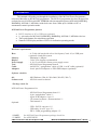
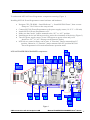
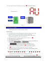
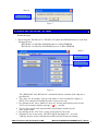
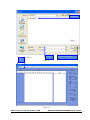
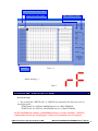
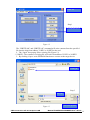
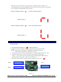
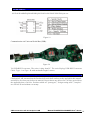
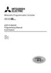
M35160 EEPROM ERASER/PROGRAMMER
Rev.2.0
M35160 ERASER/PROGRAMMER
User’s Guide
©Microcontroller-café & Checkpoint LAB
M35160 ERASER/PROGRAMMER User’s Guide
1
Table of contents
1. Introduction
3
2. Check list and requirements
3
3. Installing
4
4. Quick start
5
4.1 ERASE : PC mode
6
4.2 READ 080 / READ 160 : PC mode
8
4.3 WRITE 080 / WRITE 160 : PC mode
10
4.4 RDINC / WRINC : PC mode
12
4. 5 ERASE : AU mode
13
4.6 TEST READ (Blank check) : AU mode
14
4.7 WRITE TEST PATTERN : AU mode
15
4.8 JUMPER SETTING
15
5. Troubleshooting Guide
17
APPENDIX I
APPENDIX II : Warranty Statement
ABLE OF CONTENTS
18
18
©Microcontroller-café & Checkpoint LAB
M35160 ERASER/PROGRAMMER User’s Guide
2
Cte
1. Introduction
This manual will guide you through the installation of the M35160 Eraser/Programmer,
referenced hereafter as the M35160 programmer. The M35160 programmer has been designed for
on-board access 8/16 Kbit serial SPI EEPROM with incremental registers M35160;D160D0WQ;
D80D0WQ; M35080-3; M35080-6 with clock rates from 3 Mhz up to 10 Mhz via PC or
autonomous control operation mode.
M35160 Eraser/Programmer features
•
•
•
•
RS232 interface to PC or USB port (optional)
8 - pin socket for M35160; D160D0WQ; D80D0WQ ;M35080-3; M35080-6 devices
Three push buttons for stand alone operation
Numeric LED display and three LED’s for indication operating modes
2. Check list and requirements
Hardware requirements
- A 32-bit x86 based with a free Serial ports (Com1-10) or USB ports
(optional) a hard-disk system
- Minimum 16 Mbytes
- Color VGA display recommended
- A 10-15 volt/500 mA linear power supply source
- M35160 Eraser/Programmer board*
- An RS232C “straight-thru” cable or USB “A to B” cable (optional)*
- four 8-pins PCB adapters or ZIP8-DIP8 adapter (optional)*
Host
Memory
Display
Power supply
Tool
Cable
Adapters
Software checklist
OS
Software tool -
- MS-Windows (Win 98, Win 2000, Win XP; Win 7)
- M35160 control software*
* Package check list
M35160 Eraser/ Programmer kit:
- M35160 Eraser/Programmer board **
- 9-pin “straight-thru” cable **
- 8 pins PCB adapters: 4 pcs. **
- CD (control software , documentation) **
- This manual **
Optional:
- USB – RS232 converter ***
- USB cable “A to B” type ***
- ZIF8 – DIP8 programming adapter ***
**NOTE:
***NOTE:
See M35160 Eraser/Programmer package check list
See APPENDIX I
©Microcontroller-café & Checkpoint LAB
M35160 ERASER/PROGRAMMER User’s Guide
3
3. Installing
To understand M35160 Eraser/Programmer components meaning (Figure 1)
Installing M35160 Eraser/Programmer control software and hardware:
•
•
•
•
•
•
•
Navigate CPL CD-ROM : “Install Software” > “Install M35080 Eraser”, then execute
“Setup.exe” file. Follow to the setup wizard
Connect M35160 Eraser/Programmer to the power supply source (10-15 V >=500 mA)
Attach M35160 Eraser/Programmer to PC
Make sure that "mode" jumper mounted to the “PC” or “AU” position
Install target device into the target socket, notice the orientation of the device (Figure 3)
Turn ON power supply source, power LED appear to green colour and you'll
should see “PC” or “AU” message on the numeric display
M35160.exe control software can be start, if “Function” jumper mounted into PC
position. Otherwise, if “Function” jumper mounted into AU position M35160
Eraser/Programmer will remain autonomous operation mode
M35160 ERASER/PROGRAMMER components:
7
RST
2
3
4
5
6
8
9
LED
indicator
Beeper
Target
socket
P
C
A
U
RD
Led1
1
Serial
port
160
16
TST
15
080
Led3
13
14
Power
jack
Led2
12
10
WR
Figure 1
©Microcontroller-café & Checkpoint LAB
11
M35160 ERASER/PROGRAMMER User’s Guide
4
1 - Serial port: DE-9 (DB-9) connector (RS-232 standard)
2 - LED indicator: double digits (two single sections) numeric display
3 - Beeper: piezo buzzer
4 - Target socket: two straight PCB sockets (2.54 mm)
5 - PC: mode operation jumper. PC - personal computer mode
6 - AU: mode operation jumper: AU - autonomous operate
7 - RST: reset button for autonomous operate mode
8 - RD: READ/TEST button for autonomous operate mode
9 - Led1: control led (green color led)
10 - Power jack: DC power jack 2.1 mm
11 - WR: WRINC/ERASE button for autonomous operate mode
12 - Led2: program led (red color led)
13 - Led3: power/status led (green color led)
14 - 080: M35080 jumper. Select M35080-4; M35080-6 devices for autonomous operate mode
15 - TST: Self test mode: Select self test diagnostic mode
16 - 160: M35160 jumper. Select M3160; D160D0WQ; D80D0WQ devices for autonomous
operate mode
4. Quick start
Before connecting the power plug, make sure that the power supply source is DC and
power supply voltage matches the voltage rating of the M35160 Eraser/Programmer.
Select mode of operate Personal Computer or Autonomous by “Function” jumper:
AU mode
PC mode
Incorrect
Figure 2
NOTE: Personal Computer (PC) mode will active after Power On Reset only!
AU operation mode activation: mount jumper to AU position then press reset button
Left :
Autonomous mode, jumper mounted into AU position
Middle : Personal Computer mode, jumper mounted into PC position
Right : Incorrect installation
Jumper mounted to PC position, numeric display message: “ PC“ (Personal Computer)
Status message -->
©Microcontroller-café & Checkpoint LAB
M35160 ERASER/PROGRAMMER User’s Guide
5
AU mode jumper mounted. LED display message: “AU“ (Autonomous mode)
Status message -->
PIN # 1
PIN # 1
PIN # 1
Figure 3
4.1 ERASE : PC mode
Programming software resides in the host computer.
Practical steps:
1. Turn ON the M35160 Eraser/Programmer, insert jack plug into power jack
2. Install the target device into the target socket (M35160 marked)
Notice: 1-pin on the target socked and programming adapter "◙" marked,
which point towards pin 1 of the device (Figure 3)
3. Make sure that numeric display message matches to this one: “ PC“
4. Start "M35160.exe" control program
5. Select appropriate serial port
6. By pressing "ERASE - M35080" or "ERASE-M35160" button incremental area
bytes are erase according to the target device:
"ERASE-M35080" for M35080-3; M35080-6 devices
"ERASE-M35160" for M35160; D160D0WQ; D80D0WQ devices
7. Numeric display message will change to: “ P1“ i.e. pass one procedure,
waiting window will display progress bar and terminate button (Figure 7)
8. “ P2“ ”pass two” procedure follow after “pass one” procedure
9. Then numeric display will change one by one numbers of incremental registers
recovered to factory settings :
“ PC“
“ P1“
“ P2“
” 01”
” 02”………
” 15”
” 16”
“ PC“
The internal buzzer will duplicate every change by sound signal
10. In the end of erase procedure you’ll see on the numeric display message: “ PC“
©Microcontroller-café & Checkpoint LAB
M35160 ERASER/PROGRAMMER User’s Guide
6
And message window, as result on Figure 7
Select serial port
Step 5
Figure 4
Click ERASE button
Step 6
Figure 5
Progress bar
Step 7
Figure 6
©Microcontroller-café & Checkpoint LAB
M35160 ERASER/PROGRAMMER User’s Guide
7
Step 10
Positive result
Figure 7
4.2 READ 080 / READ 160 : PC mode
Practical steps:
1. By pressing the "READ 080" or "READ 160" button the EEPROM bytes are read from
the target device:
"READ 080” for M35080; D80D0WQ devices 8 Kbit EEPROM
"READ 160” for M35160; D160D0WQ devices 16 Kbit EEPROM
Step 4
Buffer view
Click READ button
Step 1
Figure 8
2.
3.
4.
5.
6.
The “READ 080” and “READ 160” command reads the contents of the chip into a
specified file
The “Save As” box popup. Type new file name or select existing file (Figure 9)
NOTE: The contents of existing file will re-write to new one
By clicking on the “Save“ button of “Save As” box the read function will execute.
You’ll see on numeric display message “ rF“ - read file
To view the content read, open the buffer edit dialogue window by the
“Edit” menu button
By clicking on the “File” then “ Open” menu select a file to edit
Edit data in case of necessary. The HEX/ASCII data buffer is 8 – bit wide.
TAB key may be used to switch between HEX and ASCII data for editing
©Microcontroller-café & Checkpoint LAB
M35160 ERASER/PROGRAMMER User’s Guide
8
Existing file
Step 3
Open
file
Step 5
New file
Save new or existing file
Figure 9
Figure 10
©Microcontroller-café & Checkpoint LAB
M35160 ERASER/PROGRAMMER User’s Guide
9
Return from buffer viewer / editor
Toggle between DEC to HEX
Status line
HEX / Character control
Figure 11
Status message -->
Step 3
4.3 WRITE 080 / WRITE 160 : PC mode
Practical steps:
1. By pressing the "WRITE 080" or "WRITE 160" button the file bytes are write to
the target device:
"WRITE 080” for M35080; D80D0WQ devices 8 Kbit EEPROM
"WRITE 160” for M35160; D160D0WQ devices 16 Kbit EEPROM
NOTE: EEPROM start address of EEPROM location is 32 DEC (20 HEX). "WRINC"
command must be use for changing first 32 bytes of incremental area (16 registers)
©Microcontroller-café & Checkpoint LAB
M35160 ERASER/PROGRAMMER User’s Guide 10
Buffer view
Step 1
Click WRITE button
Figure 12
The “WRITE 080” and “WRITE 160” command will write contents from the specified
file into the chip from address 32 DEC or 20 HEX to the end
2. The “Open” box popup. Select existing file (Figure 13)
***NOTE:: The contents of existing file will write from address 32 DEC or 20 HEX
3. By clicking “Open“ write EEPROM function are execute to the target device
Existing file
Step 3
Select file
Figure 13
©Microcontroller-café & Checkpoint LAB
Start write operation
M35160 ERASER/PROGRAMMER User’s Guide 11
You'll see on numeric display message “ LE“ - load EEPROM (from address 32 DEC)
Status message -->
Step 3
4.4 RDINC / WRINC : PC mode
Practical steps:
1. RDINC" button - read incremental area. This will read first sixteen bit incremental
registers from the device (M3508/M35160) into the file (Figure 9)
Buffer view
Click RDINC button
Click WRINC button
Figure 14
2. "WRINC" button – write incremental area. This will write first sixteen bit incremental
registers from the file (Figure 13) into the target device.
Figure 15
©Microcontroller-café & Checkpoint LAB
M35160 ERASER/PROGRAMMER User’s Guide 12
If the file size more than 32 bytes, you'll see warning window (Figure 15),
what telling that first 32 bytes ONLY from the file will copy into the incremental
area of the target M35080/M35160 memory.
Numeric display message “ ri“ - read incremental registers:
Status message -->
Numeric display message “ Li“ - write incremental registers:
Status message -->
4.5 ERASE : AU mode
Practical steps:
1. Re-mount mode jumper to “ AU“ position (Figure 2)
2. Make sure that “Function” jumper mounted to 160 or 080 position
NOTE: 160 position:M35080; D160D0WQ; D080D0WQ devices
080 position: M35080-3; M35080-6 devices
3. Turn ON the M35160 Eraser/Programmer, insert jack plug into power jack
4. Install the target device into the target socket (M35160 marked)
Notice: 1-pin on the target socked and programming adapter "◙" marked,
which point towards pin 1 of the device (Figure 3)
5. Make sure that numeric display message matches to this one: “ AU“
Step 6
Press RS button
Step 2
Function jumper
Step 7
Press WR button
Figure 16
©Microcontroller-café & Checkpoint LAB
M35160 ERASER/PROGRAMMER User’s Guide 13
6. Press “RS” button for initialization hardware before erase function
7. Press “WR” button to start erase procedure
8. Numeric display will change one by one numbers of incremental registers
recovered to factory settings already:
“ AU“
“ P1“
“ P2“
” 01”
” 02”………
” 15”
” 16”
“ --“
9. In the end of erase procedure you’ll see on the numeric display message: “ --“
Status message -->
4.6 TEST READ (Blank check) : AU mode start
Test read function will check first 32 byte page.
If the data equal to zeros the numeric display will return message: “ oo“ .
If the data is not equal to zeros the numeric display will return message: “ EE“
1. Mode jumper mounted to “ AU“ position (Figure 2)
2. “Function” jumper must be mounted to any position 160/TST/080
for test read (blank check) function
3. Press RS button
4. Press RD button
5. Check result message on the numeric display. “ oo“ : first 32 bytes is 0x00,
from now device is blank.
Press RD button
Step 4
Press RS button
Step 3
Function jumper
Step 2
Figure 17
©Microcontroller-café & Checkpoint LAB
M35160 ERASER/PROGRAMMER User’s Guide 14
Status message -->
4.7 WRITE TEST PATTERN : AU mode start
Write test pattern function will write test sequence into first 32 byte page. Each incremental
register will write automatically with 0xAA55 value (Figure 11).
1. Mode jumper mounted to “ AU“ position (Figure 2)
2. “Function” jumper must be mounted to TST position for write test pattern function
3. Press RS button
4. Press WR button
Press RS button
Step 3
Press WR button
Function jumper
Step 4
Step 1
Figure 18
4.8 JUMPER SETTINGS start
A master microcontroller and the five jumpers control the hardware settings of the M35160
Eraser/ Programmer. Autonomous operation mode settings see Table 1, Personal computer
mode settings see Table 2. Incorrect installation see Table 3
OPERATE MODE (AU)
JUMPER(s) SETTINGS
ERASE MODE M35160;
D160D0WQ/D80D0WQ
ERASE MODE M35080-3;
M35080-6
TEST MODE
AU ⁿ
PC ⁿ
160 ⁿ
TST ⁿ
080 ⁿ
Table 1
©Microcontroller-café & Checkpoint LAB
M35160 ERASER/PROGRAMMER User’s Guide 15
ⁿ AU: autonomous stand alone mode
ⁿ PC: personal computer mode
ⁿ 160: M35160/D160D0WQ/D80D0WQ device selection
ⁿ TST: test mode
Open, no jumper
Short, jumper mounted
Don't care
To configure M35160 Eraser/Programmer for usage with Personal Computer jumper must be
mounted to PC position. Rest positions don't care for this case.
OPERATE MODE (PC)
JUMPER(s) SETTINGS
ERASE MODE M35160;
D160D0WQ/D80D0WQ
ERASE MODE M35080-3;
M35080-6
TEST MODE
AU ⁿ
PC ⁿ
160 ⁿ
TST ⁿ
080 ⁿ
Table 2
OPERATE MODES
INCORRECT
JUMPER(s) SETTINGS
ERASE MODE M35160;
D160D0WQ/D80D0WQ
ERASE MODE M35080-3;
M35080-6
TEST MODE
AU ⁿ
PC ⁿ
160 ⁿ
TST ⁿ
080 ⁿ
Table 3
©Microcontroller-café & Checkpoint LAB
M35160 ERASER/PROGRAMMER User’s Guide 16
5 Troubleshooting Guide start
To avoid most comment problems to using the tool please follow to the recommendations:
NOTE: Save original data from M35160/D160D0WQ/D80D0WQ/M35080 to a file, before
making any changes . Use “READ 160” or "READ 080" function to save data to a binary file.
Before to make any changes, such as writing a lower value to the incremental registers of a
target memory make sure that incremental area erased, if no execute “WRINC” command.
---------------------------------------------------------------------------------------------------------------◆ Problem:
The Led3 is not ON.
◆ Reason:
DC cable is broken or wrong power supply (or wrong polarity) is used
◆ Solution:
Check cable and connect the DC power cable to the DC jack or check that the power
supply source is DC type 10-15 V, min. 500 mA
------------------------------------------------------------------------------------------------------------------◆ Problem:
Programmer do not recognize a serial port
Figure 19
◆ Reason:
Serial port dot not exist
◆ Solution:
Select appropriate serial port
------------------------------------------------------------------------------------------------------------------◆ Problem:
Led 2 endless blinking AU mode / PC mode
◆ Reason:
Target memory M3510/D160D0WQ/D080D0WQ/M35080 error (not erased)
◆ Solution:
Pay attention to first pin orientation target IC into the target socket,
short circuits on the programming adapter, then try again
------------------------------------------------------------------------------------------------------------------◆ Problem:
Numeric display message “ EE“
◆ Reason:
Target memory M3510/D160D0WQ/D080D0WQ/M35080 error (not erased)
◆ Solution:
Pay attention to first pin orientation target IC into the target socket,
short circuits on the programming adapter, then try again
©Microcontroller-café & Checkpoint LAB
M35160 ERASER/PROGRAMMER User’s Guide 17
APPENDIX I start
M35160/D160D0WQ/D080D0WQ/M35080V6/M35080VP/M35080 pin out:
Figure 19
Communication via Universal Serial Bus (USB):
Figure 20
Via USB-RS232 converter. The series-A plug: host PC. The series B-plug: USB-RS232 converter
Cable: Type - A to Type - B with maximum length 3 meters.
APPENDIX II : Warranty Statement start
Checkpoint LAB warrants that the Product delivered shall conform to the applicable this manual.
and shell be free from any defects in material. Report about any defects for a 45 days period from
the applicable date of invoice. Products which are "prototypes", "design testing units", "samples"
are sold AS IS and without a warranty.
©Microcontroller-café & Checkpoint LAB
M35160 ERASER/PROGRAMMER User’s Guide 18