1
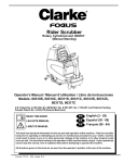
M A X I M I Z I N G
Y O U R
P E R F O R M A N C E
A T
S E A
Instruction Manual
M
A
N
U
A
L
Simrad RD68
Fixed DSC VHF Radio
III
RD68 VHF
© 2005 Simrad Ltd
The technical data, information and illustrations contained in this publication were to the best of our knowledge correct
at the time of going to print. We reserve the right to change specifications, equipment, installation and maintenance
instructions without notice as part of our policy of continuous development and improvement.
No part of this publication may be reproduced, stored in a retrieval system, or transmitted in any form, electronic or
otherwise without prior permission from Simrad Ltd.
No liability can be accepted for any inaccuracies or omissions in the publication, although every care has been taken
to make it as complete and accurate as possible.
IV
Part No. E03912 Issue 2.0 14-Feb-05 CR/MDL
Instruction Manual
1 GENERAL
1.1
1.2
1.3
1.4
Introduction ...........................................................................
Licensing ...............................................................................
Entering MMSI numbers .......................................................
Group ID MMSI ....................................................................
7
8
9
10
2 OPERATION
2.1
2.2
2.3
2.4
General ..................................................................................
Rotary controls ......................................................................
Backlighting ..........................................................................
Changing channels ................................................................
2.4.1 Standard International channels ..................................
2.4.2 Auxiliary & Private channels ......................................
2.5 Transmit power ......................................................................
2.6 Making a DSC call ................................................................
2.7 Making a Distress Alert call ................................................
2.8 Receiving a DSC call ............................................................
2.9 Dual Watch ............................................................................
2.10 Tri-Watch .............................................................................
2.11 Scan mode ............................................................................
2.11.1 Inhibiting channels from scan ...................................
2.12 Memory Scan ......................................................................
2.12.1 Add/remove channels from Memory Scan ...............
2.13 Priority & User channel select ............................................
2.13.1 Programming the User channel ................................
2.14 Viewing the call log .............................................................
11
11
12
12
12
13
14
14
17
19
20
21
22
22
23
24
25
25
26
3 MISCELLANEOUS FUNCTIONS
3.1
3.2
3.3
3.4
Adjusting the LCD contrast ...................................................
Entering position and time manually ....................................
Entering local time ................................................................
Viewing the directory ............................................................
3.4.1 Adding an entry to the directory .................................
3.4.2 Editing/deleting an entry .............................................
3.5 Disabling the key beep ..........................................................
3.6 Second country mode ............................................................
3.7 Speaker mute (handset models only) ....................................
27
28
30
31
32
33
35
36
36
4 INSTALLATION
4.1 VHF installation ....................................................................
4.2 Antenna installation ..............................................................
4.3 Electrical interference suppression ........................................
37
40
42
V
RD68 VHF
5 APPENDIX
5.1 Operating procedures .............................................................
5.1.1 Sending a Distress Alert ..............................................
5.1.2 Acknowledging and relaying a Distress Alert ............
5.1.3 Cancelling a Distress Alert .........................................
5.1.4 Alerting all vessels within range .................................
5.1.5 Calling a coast radio station ........................................
5.1.6 Making an intership call .............................................
5.2 NMEA sentences received .....................................................
5.3 Transmission range ................................................................
5.4 Channel frequencies ..............................................................
5.5 Troubleshooting .....................................................................
5.6 Accessories ............................................................................
5.7 Technical specifications .........................................................
5.8 Dimensions ............................................................................
5.9 Declaration of Conformity ....................................................
5.10 Service & Warranty .............................................................
VI
43
43
43
44
44
44
44
44
45
46
47
48
48
49
50
51
E03912 Issue 2.0
Instruction Manual
1 GENERAL
1.1 Introduction
The RD68 is a combined VHF radio and Class D Digital Selective Calling (DSC) unit. It supports the latest GMDSS requirements for non-SOLAS vessels from the International Maritime
Organization (IMO). This will enable you to make digitally
selected calls, which are quicker and simpler to make than traditional voice calls using channel 16. Should a distress situation
occur, with the RD68 you can quickly raise an alert, indicating
your identity, your position, and automatically establish distress
communication on the emergency voice channel.
The RD68 is robustly constructed using a pressure die-cast aluminum case for effective heat dissipation, ensuring maximum
transmission performance even after many hours’ constant use.
Thank you for choosing Simrad!
If you are pleased with your VHF, we hope you will be interested in our range of marine electronic equipment, which is manufactured to the same high standards as the RD68. Please contact
your nearest Simrad Agent for a catalog showing our increasing
range of high tech navigational instruments, GPS, Autopilots,
Radar, Fishfinders and VHF radio sets.
Simrad operates a policy of continual development and reserves
the right to alter and improve the specification of their products
without notice.
Fig 1.1 - RD68 combined VHF & DSC
E03912 Issue 2.0
7
RD68 VHF
1.2 Licensing
Note
Prior to use please check the national licensing requirements
for operators.
In the UK license applications and queries should be made to
the following authority:
Ship Radio Licencing
Radio Licencing Centre
The Post Office
PO Box 1495
Bristol BS99 3QS
Website: www.radiolicencecentre.co.uk/rlc
A set may only be operated by or under the supervision of the
holder of a Marine Radio Operator’s Certificate of Competence
and Authority to Operate. This is awarded on completion of the
Marine Short Range Certificate course administered by the Royal
Yachting Association:
Royal Yachting Association
RYA House
Ensign Way
Hamble
Southampton SO31 4YA
Website: www.rya.org.uk
Tel. 0845 345 0400
Holders of the Restricted Certificate of Competence in Radiotelephony (which covers MF/HF SSB, etc.) do not need a separate VHF certificate.
In all other countries, please contact your regional authority for
information.
Note
North American Users – To meet FCC (Federal Communications Commission) rules on Radio Frequency Exposure, it is
recommended that the VHF antenna is mounted at least 3 m
(10 ft) away from any area accessible to any personnel on board.
If this distance is achieved by vertical separation, the antenna
must be at least 5 m (16.5 ft) above deck. This guideline applies
only to antennas not exceeding 9dBi gain.
WARNING
Failure to observe these recommendations may
expose those within the MPE (maximum permitted exposure) radius of 3 m (10 ft) to RF absorption levels that exceed the FCC safe limits.
8
E03912 Issue 2.0
Instruction Manual
1.3 Entering MMSI numbers
At the time of issue of your vessel’s radio license, an MMSI
(Maritime Mobile Service Identifier) must be requested. This is
a nine-digit number which must be permanently entered into the
RD68 when the radio is first set up, otherwise the DSC functions cannot be accessed.
Note
If the boat or the RD68 are subsequently sold, the radio must be
returned to an authorized Simrad agent for the MMSI number
to be erased and the new owner’s MMSI number entered.
➞ For licensing details, please refer to section 1.2.
To enter the vessel’s MMSI number:
12:43
DSC
INT
T/W
Hi
Lite M/S
Scan
Rx
12:43
52o16N
001o23E
Rx
Rad
Menu
12:43
52o16N
001o23E
Rx
DSC
LCD
Posn
More
/continued
E03912 Issue 2.0
9
RD68 VHF
52o16N
001o23E
Rx
DSC
MMSI
Dir
More
12:44
Ships MMSI
*********
Group MMSI
000000000
DSC
Press this key to enter
the MMSI number
Press this key to enter
the Group ID
12:44
Enter the MMSI number
using the keypad.
Press E to enter
Note
Ships MMSI
002325___
DSC
If an error is made, press to move back and edit the number.
You will be asked to confirm the number. Re-enter the MMSI
and press E.
CAUTION
It is important that the MMSI entered is checked carefully, as it can only be entered once. To change the
MMSI number after it has been programmed, the unit
must be returned to an authorized Simrad Dealer to
erase the existing number.
1.4 Group ID MMSI
For boats that are part of a flotilla, racing fleet, or other group, a
Group ID MMSI number can also be entered while in the
MMSI entry screen by pressing softkey 4. Follow the procedure
described above to enter the Group MMSI. Unlike the vessel
MMSI number, this can be changed later by the user.
10
E03912 Issue 2.0
Instruction Manual
2 OPERATION
2.1 General
The RD68 VHF is very simple to operate, with the controls
falling into five groups:
1
SOFTKEY LABEL
SOFTKEY LABEL
SOFTKEY LABEL
SOFTKEY LABEL
SC1
SC2
SC3
SC4
2
3
4
Softkeys & labels
1. The rotary Volume (On/Off) & Squelch controls.
2. The alphanumeric keypad used to select the channel, MMSI
number, etc.
3. The dedicated controls, for commonly used functions such
as output power, Dual Watch, and channel 16 select, etc.
4. The four softkeys to the right of the display are multifunction keys whose function changes depending on which
menu is displayed. The label showing the current function for
each softkey appears on the right side of the display (see left).
5. There is also a Distress button under a sliding cover. This
must only be used in an emergency (see section 5.1).
The radio functions are split into two main modes:
• Radio mode allows access to the standard VHF radio functions, such as Tri-Watch, scanning, etc.
• DSC mode covers the digital selective calling functions.
These modes are toggled by pressing softkey 1 (labeled DSC or
RAD).
At any stage of the DSC mode menu structure, pressing the DSC
softkey will return to the DSC mode main menu. At any stage
of the DSC mode menu structure, pressing the C key will cancel any unconfirmed action, or step back one level in the menu
structure.
Note
Some menu options will only be displayed if the relevant information is available.
If the radio is receiving NMEA GPS data, the current Lat/Long
will be displayed when in DSC mode, and the time will be displayed in both Radio and DSC modes in 24-hour UTC (GMT)
format (the local time can also be entered).
2.2 Rotary controls
Switch the radio on by turning the VOLUME knob clockwise.
To increase the volume, turn the knob further clockwise. Turn
the knob fully counterclockwise to switch off.
The SQUELCH knob is used to adjust the receiver muting
threshold (squelch) level. To cut out weaker signals, increase
the squelch until the background interference noise disappears.
To receive weaker signals, decrease the squelch.
E03912 Issue 2.0
11
RD68 VHF
2.3 Backlighting ( )
12:40
INT
Hi
Lite
Rx
DSC
T/W
M/S
Scan
There are five levels of brightness – press and hold the key
to step through and release when the required level is shown.
2.4 Changing channels
2.4.1 Standard International channels
12:40
Enter the channel
number using the
numeric keypad
INT Pvt
Wx
Hi
Lite Aux
Rx Aux
12:41
If channel selection is
not confirmed within 2
seconds (by pressing E),
the radio will revert to
the original channel
Note
12
INT
Hi
Lite
Rx
DSC
T/W
M/S
Scan
To select channels, the RD68 will need to be in Radio mode. If
in DSC mode, press the RAD softkey before entering the channel number.
E03912 Issue 2.0
Instruction Manual
2.4.2 Auxiliary & Private channels
This function is used to select channels which are not part of
the standard International channel set, for example, channels M
and M2 in the UK, or the US Wx Weather channels.
Standard availability of channels includes M & M2 in the UK, or
one or more of L1–L3 or F1–F3 in Scandinavia (cf. section 5.3).
Note
STEP 1
To select an Auxiliary channel
press any numeric key –
To select a Weather or
Private channel, press the
relevant number key (e.g. 2 for
Private Ch2 or Weather Ch2 –
12:41
INT Pvt
Wx
Hi
Lite Aux
Rx Aux
12:41
INT Pvt
Wx
Hi
Lite Aux
Rx Aux
STEP 2 (Private)
Press Pvt to select
Private Ch2
STEP 2 (Weather)
Press Wx to select
Weather Ch2
12:42
INT Pvt
Wx
Hi
Lite Aux
Rx Aux
STEP 2 (Auxiliary)
Press Aux▲ or Aux▼ to
scroll through the available
Auxiliary channels &
press E to select
E03912 Issue 2.0
12:42
INT Pvt
Wx
Hi
Lite Aux
Rx Aux
13
RD68 VHF
2.5 Transmit power
This function allows toggling of the transmit power between
25W (Hi) and 1W (Lo) for short range transmissions, for example, when in a marina. This preserves battery power.
12:42
INT
Hi
Lite
Rx
DSC
T/W
M/S
Scan
12:42
INT
Lo
Lite
Rx
Note
DSC
T/W
M/S
Scan
Regulations restrict some channels, such as 15 and 17, to low
power only, in which case this key will have no effect.
2.6 Making a DSC call
Press the DSC softkey to enter DSC mode:
12:43
DSC
INT
T/W
Hi
Lite M/S
Scan
Rx
/continued
14
E03912 Issue 2.0
Instruction Manual
12:43
52o16N
001o23E
Rx
SELECTING CALL TYPE
Press Type to scroll through
the different types of calls
(see also p. 16):
Rad
Call
Menu
MANUAL ENTRY
To manually enter an MMSI
number (Routine call):
12:43
12:43
Routine to
Excalibur
Rx
Type
Dir
Ch26
Send
Routine to
________
Usekey to
correct any
mistakes
Rx
Use keypad to type in
MMSI number and press
E, then Send
12:43
All Ships
Safety
Rx
Type
Ch16
Send
12:43
Routine to
002325567
On Ch26
Press E to send
12:43
All Ships
Urgency
Rx
Type
12:43
Ch16
Send
Waiting for
acknowledge
Rx
Press Stop to
cancel call
12:44
Group call
009999999
Rx
Type
Ch26
Send
Select call type and
press Send to transmit
E03912 Issue 2.0
Stop
Only displayed if a Group
MMSI number has been
entered (see section 1.3)
/continued
15
RD68 VHF
12:44
52o16N
001o23E
Rx
MMSI DIRECTORY
Use the directory (see section 3.4) to select a commonly used MMSI:
Rad
Call
Menu
VOICE CHANNEL SELECTION
To specify which channel is to be
used in voice communication
12:44
Routine to
Excalibur
Rx
Type
Dir
Ch26
Send
Press Dir to scroll
through directory
entries
Press softkey 3 (ChXX) to
specify voice channel.
12:44
Routine to
Hbrmaster
Rx
Type
Dir
Ch26
Send
12:43
Routine to
Hbrmaster
On Ch26
Press E to send
12:45
Press Send
to transmit
call
Routine to
Excalibur
Rx
Type
Dir
Ch26
Send
Voice channel can only be
specified on Routine, Safety
and Group calls (simplex only).
Urgency and Distress calls
are set to Ch16.
When making a Routine call to
a coast station (MMSI begins
with “00”), the option
to select a voice channel
is not available.
12:45
12:43
Waiting for
acknowledge
Rx
Press Stop to
cancel call
16
Reply on channel
17
Rx
Stop
Chan
Press Chan to scroll through a
selection of pre-programmed
channels, or type in the channel
number and press E.
E03912 Issue 2.0
Instruction Manual
2.7 Making a Distress Alert call
WARNING
This call should only be made if the vessel is in a
genuine distress situation. It is an offense to send
a Distress Alert call if the vessel or crew are not in
grave and imminent danger (see section 5.1).
The DISTRESS button is located under a protective cover that
must be slid back before the button can be pressed. Press the
DISTRESS button to access the Distress Alert screen:
12:46
Distress Alert
52o16N 001o23E
12:46 UTC
Undefined
12:46
Distress Alert
52o16N 001o23E
12:46 UTC
Abandoning
Collision
Grounding
Piracy
Listing
M.O.B
Sinking
Fire
Adrift
Flooding
Pressto scroll
through distress categories
/continued
E03912 Issue 2.0
17
RD68 VHF
12:47
DISTRESS ALERT
Sending in
5 secs
To send the call, press and hold the DISTRESS key for five
seconds. A countdown to the transmission will be displayed.
Release the key at any time during this countdown to abort the
transmission and press C to return to the main menu.
The Distress Alert transmission contains the following data:
• The vessel’s MMSI
• The vessel’s position (either from the NMEA 0183 input, or
manually entered)
• The time (from NMEA or manual)
• The nature of the distress
Note
If the boat’s position and time are not being received via the
NMEA interface, then the display will allow this data to be
entered manually (refer to section 3.2 for more details).
After the Distress Alert has been sent, the RD68 will tune to
channel 16 and will automatically repeat the alert approximately
every four minutes, until either an acknowledgment is received
or C is pressed (it is not recommended that the Distress Alert is
cancelled manually by pressing C, unless you are requested to
do so by the rescue authorities).
While the Distress Alert remains active, an intermittent alarm
will continue to sound.
When an acknowledgment is received from the Rescue Coordination Center, this will automatically cancel the Distress
Alert transmission. The subsequent rescue co-ordination will be
performed using the voice working channel.
18
E03912 Issue 2.0
Instruction Manual
2.8 Receiving a DSC call
When a call is received, the RD68 will ring and the display will
show the call information.
Press Ack (for individual calls requesting acknowledgment
only) or OK to cancel and switch to the working channel. Press
Stop to cancel ring only.
Individual Routine call
Individual Routine call from
MMSI stored in directory
12:48
12:48
Ack
Individual
Routine
Stop
From 987654321
Ch06
Ack
Individual
Routine
Stop
From Excalibur
Ch06
All Ships Safety call
All Ships Urgency call
12:48
12:48
OK
All Ships
Safety
Stop
From 987654321
Ch16
OK
All Ships
Urgency
Stop
From 987654321
Ch16
Group call
Distress Alert call
12:50
12:50
OK
Group call
Routine
Stop
From Excalibur
Ch06
Distress
OK
Alert
From 987654321
Ch16
Press ▼ key for more
information
12:50
Sinking
23o47’N
001o35’E
12:50 UTC
E03912 Issue 2.0
OK
19
RD68 VHF
2.9 Dual Watch
Dual Watch allows the radio to scan between a selected working
channel and the priority channel (normally Ch16).
12:52
Select a working channel
INT
Hi
Lite
Rx
Press the D/W key
INT
Hi
Lite
Rx
DSC
T/W
M/S
Scan
12:52
DSC
T/W
M/S
Scan
12:52
12:52
INT DSC
Hi
Ch16
D/W
INT DSC
Hi
Ch16
D/W
The RD68 will monitor the working channel and the priority channel sequentially
Note
20
Normal VHF functions will not be available when in Dual Watch
mode. To change channel or transmit, press 16, D/W, or C to
exit Dual Watch. DSC functions can still be accessed by pressing DSC; however, sending a DSC call will automatically cancel Dual Watch.
E03912 Issue 2.0
Instruction Manual
2.10 Tri-Watch
Tri-Watch operates on the same principle as Dual Watch, but
this function scans between the working channel, priority channel, and the User channel. For more information on the User
channel and how it is specified, please refer to section 2.13.
12:53
Select a working channel
and press the T/W key
INT
Hi
Lite
Rx
DSC
T/W
M/S
Scan
12:53
INT DSC
Adv
Hi
Ch16
T/W
12:53
12:53
INT DSC
Adv
Hi
Ch16
T/W
INT DSC
Adv
Hi
Ch16
T/W
12:54
Pressing Adv will manually
advance the scan onto the next
channel in the sequence
Note
E03912 Issue 2.0
INT DSC
Adv
Hi
Ch16
T/W
As with Dual Watch, normal VHF functions will not be available
when in Tri-Watch mode. Exit Tri-Watch by pressing 16 or C.
21
RD68 VHF
2.11 Scan mode
The Scan function cycles the RD68 sequentially through each
enabled channel, pausing when a signal is detected.
12:54
INT
Hi
Lite
Rx
DSC
T/W
M/S
Scan
12:54
Press Adv to manually
advance to the next channel in
the scan sequence
Note
INT DSC
Hi
Lite Inh
Scan Adv
While in Scan mode, normal VHF functions are not available.
To exit Scan mode, press C or 16.
2.11.1 Inhibiting channels from scan
In some areas the Scan function may repeatedly lock on a channel at each cycle, for example, if it is transmitting a carrier signal. Rather than pressing Adv each cycle, selected channels
may be inhibited from the scan cycle.
1. While in Scan mode
2. In VHF mode
12:55
INT DSC
Scan
Inh Inh
Scan Adv
12:55
INT
Scan
Inh
Rx
DSC
T/W
M/S
Scan
Select channel to be
inhibited, then press and
hold Scan (double beep)
Press
and hold
22
E03912 Issue 2.0
Instruction Manual
To re-enable an inhibited channel into the scan cycle, repeat
sequence 2:
12:55
Select channel to be enabled
then press and hold Scan
(double beep)
INT
Scan
Ena
Rx
DSC
T/W
M/S
Scan
Press and
hold
2.12 Memory Scan
Like the Scan function, Memory Scan will cycle sequentially
through the channels, but only those which have been preselected.
➞ Refer to the next subsection 2.12.1 for more information on
preselecting Memory Scan channels.
12:55
INT DSC
T/W
Hi
Lite M/S
Scan
Rx
12:56
Press Adv to manually
advance to the next channel in
the Memory Scan sequence
Note
E03912 Issue 2.0
INT DSC
Hi
Lite Adv
M/S Del
While in Memory Scan mode, normal VHF functions are not
available. To exit Memory Scan mode, press C or 16.
23
RD68 VHF
2.12.1 Add/remove channels from
Memory Scan
To add a channel to the Memory Scan cycle:
12:57
Select the required
channel
INT
Hi
Lite
Rx
DSC
T/W
M/S
Scan
12:57
INT DSC
M/S T/W
Sel M/S
Rx Scan
Press and hold M/S
(double beep)
Press
and hold
To delete a pre-selected channel from the Memory Scan cycle:
1. While in Memory Scan mode
INT
M/S
Del
M/S
2. In VHF mode
12:57
12:57
DSC
INT DSC
M/S T/W
Del M/S
Rx Scan
Adv
Del
Select channel to be
deleted, then press and
hold M/S (double beep)
Press
and hold
24
E03912 Issue 2.0
Instruction Manual
2.13 Priority & User channel select
The priority channel (usually Ch16, depending on the configuration of the RD68) can be accessed immediately by pressing 16.
This will cancel any function currently in operation.
The User channel is a programmable priority channel which is
accessed by pressing 16 twice:
12:57
INT
Hi
Lite
Rx
DSC
T/W
M/S
Scan
Press 16 twice
12:58
INT
Hi
User
Rx
DSC
T/W
M/S
Scan
2.13.1 Programming the User channel
12:58
Select the required channel
Press and hold T/W
(double beep)
INT DSC
T/W
Hi
Lite M/S
Rx Scan
Press
and hold
12:58
INT
User
Sel
M/S
E03912 Issue 2.0
DSC
T/W
M/S
Scan
25
RD68 VHF
2.14 Viewing the call log
The last 16 incoming DSC calls are logged by the RD68 and
can be viewed later (this function will not be displayed if no
calls have been received).
12:58
52o16N
001o23E
Rx
Rad
Call
Log
Menu
12:58
The most recent
call is shown first
Individual
Routine
From
987654321
DSC
Back
12:59
All Ships
Safety
From
987654321
DSC
Back
Next
12:59
Press ▼ to view any
extra information
Distress
Alert
From
987654321
DSC
Back
Next
12:59
Sinking
23o47’N
001o35’E
12:50 UTC
26
DSC
Back
Next
E03912 Issue 2.0
Instruction Manual
3 MISCELLANEOUS FUNCTIONS
3.1 Adjusting the LCD contrast
13:00
52o16N
001o23E
Rx
Rad
Call
Log
Menu
13:00
52o16N
001o23E
Rx
Press ▲ and ▼ keys to
adjust contrast:
max = +7
min = –8
DSC
LCD
Posn
More
13:00
Contrast
+2
DSC
Rx
Press DSC to return to
main menu or C to cancel
E03912 Issue 2.0
27
RD68 VHF
3.2 Entering position and time manually
The boat’s position and the time (transmitted as part of a Distress Alert call) would normally be given by an interfaced GPS.
If this is not available, the information can be manually entered:
If no GPS information is
being received, the clock is not
shown and the display shows
“No position available”
No position Rad
available Call
Log
Menu
Rx
No position
available
Rx
DSC
LCD
Posn
More
99o99
999o99
88:88 UTC
DSC
Posn
UTC
Enter Lat and Long
using the keypad
-o--+
---o--+
88:88 UTC
DSC
Press N or S for
Latitude
52o16
---o--+
88:88 UTC
UTC
13:02
N
S
/continued
28
E03912 Issue 2.0
Instruction Manual
Press E or W for Longitude
reference from meridian
52o16N
001o23
88:88 UTC
Press E (Enter) key to confirm
position and select time
52o16N
001o23E
-:-- UTC
Enter UTC time
(24-hour format)
using keypad and
press E to confirm
E
W
DSC
Posn
52o16N
001o23E
13:02 UTC
52o16N
001o23E
13:02 UTC
DSC
Posn
UTC
Note
The display will now show the manual Lat and Long when in
DSC mode, but the clock display will not be shown (this is only
available if NMEA position and time data is being received).
Note
This option will not be available if position and time data is
being received via the NMEA input.
If this option is used, the
RD68 will request that
the position and time be
updated regularly
E03912 Issue 2.0
POSITION
IS OVER
4 HOURS
OLD
Rad
Posn
29
RD68 VHF
3.3 Entering local time
When a GPS is connected to the RD68 via the NMEA interface,
the display will show the UTC (GMT) time in the top righthand corner. This can be changed to the local time if required:
13:03
52o16N
150o23E
Rx
Rad
Call
Log
Menu
13:03
52o16N
150o23E
Rx
DSC
LCD
Posn
More
13:03
52o16N
150o23E
Rx
DSC
MMSI
Dir
More
13:03
52o16N
150o23E
Rx
DSC
Beep
Time
13:03
Use arrow keys to
adjust to local time and
press DSC to return to
main menu
Adjust
local time
DSC
Rx
/continued
30
E03912 Issue 2.0
Instruction Manual
18:03
The display will now
show local time
52o16N
150o23E
Rx
Rad
Call
Log
Menu
3.4 Viewing the directory
The directory allows up to 16 MMSI numbers to be stored in
the RD68’s memory. These can then be recalled when making
an Individual Routine call:
18:03
52o16N
150o23E
Rx
Rad
Call
Log
Menu
18:04
52o16N
150o23E
Rx
DSC
LCD
Posn
More
18:04
52o16N
150o23E
Rx
DSC
MMSI
Dir
More
18:04
The main directory
screen shows the number of directory entries
Directory
Used 04/16
DSC
View
Add
/continued
E03912 Issue 2.0
31
RD68 VHF
18:04
Directory
01
Excalibur
002321167
DSC
Next
Edit
18:04
Directory
02
Saucy Sue
002320588
DSC
Back
Next
Edit
3.4.1 Adding an entry to the directory
18:05
Directory
Used 04/16
Enter name using the keypad (10 chars max) -
DSC
View
Add
18:05
Name:
_________
DSC
Press E to confirm name -
18:06
Enter MMSI number, then
press E to save entry to directory
32
Name:
Sea Mist
MMSI:
________
DSC
E03912 Issue 2.0
Instruction Manual
3.4.2 Editing/deleting an entry
To edit an existing entry:
18:06
The main directory
screen shows the
number of entries
Directory
Used 05/16
DSC
View
Add
18:06
Directory
01
Excalibur
002321167
DSC
Next
Edit
18:06
Directory
01
Excalibur
002321167
DSC
Del
Edit MMSI number
18:06
Re-enter the MMSI
using the keypad.
Press E to enter
Name:
Excalibur
MMSI:
00 ______
DSC
Edit Name
18:06
Re-enter the name
using the keypad.
Press E to enter
E03912 Issue 2.0
Name:
Ba _______
MMSI:
002321167
DSC
33
RD68 VHF
To delete an entry from the directory:
18:06
Directory
Used 05/16
DSC
View
Add
18:07
Directory
01
Excalibur
002321167
DSC
Next
Edit
18:07
Directory
01
Excalibur
002321167
DSC
Del
18:07
Directory
Delete ?
Excalibur
002321167
34
DSC
No
Yes
E03912 Issue 2.0
Instruction Manual
3.5 Disabling the key beep
All key presses on the RD68 are normally confirmed by a
“beep” – this feature can be disabled:
18:07
52o16N
150o23E
Rx
Rad
Call
Log
Menu
18:07
52o16N
150o23E
Rx
DSC
LCD
Posn
More
18:07
52o16N
150o23E
Rx
DSC
MMSI
Dir
More
18:07
52o16N
150o23E
Rx
DSC
Beep
Time
To re-enable the key beep, repeat the above key sequence.
Note
E03912 Issue 2.0
The key beep will be disabled on all first level functions. Second
level functions which are accessed by pressing and holding a
key (e.g. setting the User channel or adding a channel to the
Memory Scan cycle) will still be audibly confirmed by a double
beep – this cannot be disabled.
35
RD68 VHF
3.6 Second country mode
In countries where it is permitted, the RD68 can operate on a
secondary set of channels, such as the USA channels:
Radio switched off
Press and hold
18:07
Turn radio on
USA DSC
M/S T/W
Sel M/S
Rx Scan
Note
Channel sets available will depend on programming. Please
enquire with your national licensing authority for details of
permitted channel sets in your country (see also section 5.4).
Note
The radio will revert to the International channel set when it is
switched off.
3.7 Speaker mute (handset models only)
On radios fitted with a handset, lifting the handset from the cradle will normally mute the loudspeaker. However, this can be
disabled, so that the loudspeaker will remain on when the handset is lifted, and incoming transmissions will be heard both in
the handset earpiece and the loudspeaker.
Press and
hold
Radio switched off
Turn radio on
To restore speaker muting, repeat the above procedure.
36
E03912 Issue 2.0
Instruction Manual
4 INSTALLATION
4.1 VHF installation
The radio should be sited so that engine noise and vibration or
other background noise do not make it difficult for the operator
to hear.
Although the RD68 radio is waterproof when flush mounted, it
is recommended that it is not installed where it will be exposed
to continuous direct sunlight, as this will eventually damage the
LCD display.
As microphones and loudspeakers contain powerful magnets,
the radio should not be installed within 1 m (3 ft 3 in) of any
compasses, whether magnetic or electronic.
The fins on the back of the case act as a heatsink to dissipate
heat generated by the set when in use, which maintains the high
efficiency of the radio. The free circulation of air is essential –
when mounting the radio in an enclosed space, ensure that the
space is vented.
Desktop mounting
Overhead mounting
Fig 4.1 - Standard mounting options
88 mm (3.5 in)
The VHF is supplied with a reversible mounting bracket. This
can be used to mount the VHF on the chart table or on an overhead bulkhead (Fig 4.1). The bracket is fixed in place using four
No. 10 x 3/4 in screws (supplied). Before installing, ensure that
there is at least 88 mm (3.5 in) vertical clearance and 100 mm
(3.9 in) horizontal clearance behind the bracket to allow the
radio to fit (Fig 4.2).
100 mm (3.9 in)
Fig 4.2 - Minimum clearance required
E03912 Issue 2.0
37
RD68 VHF
The radio is fixed to the bracket using a simple clamp arrangement. The peg on the left side of the radio is slotted into the
hole in the bracket. The clamp on the right side of the radio can
then be slid into the slotted aperture on the bracket and tightened to hold the radio firmly in place (Fig 4.3). The rake angle
of the radio can be adjusted by slackening the clamp.
3
1
2
1. Fit locating peg (left side) into hole in bracket
2. Slide locking clamp (right) into slot in bracket
3. Tighten clamp
Fig 4.3 - Fixing the VHF to the bracket
An alternative mounting method is to use the flush mounting kit
(FMB1000:BK, supplied separately). This allows the radio to
be neatly installed inside a bulkhead, so that only the fascia of
the radio is visible.
➞ For more details of this and other accessories available,
please refer to section 5.6.
38
E03912 Issue 2.0
Instruction Manual
The RD68 has five electrical connections – the handset/fistmike
socket is on the front panel below the LCD display (Fig 4.4A).
The other four are situated on the back of the case: the antenna
socket is on the left (Fig 4.4B); DC power is supplied to the set
via a two-core flying lead (Fig 4.4C); the NMEA input connections (Fig 4.4D) allow a GPS to be interfaced, below which is a
3.5 mm jack socket for an optional extension speaker (Fig 4.4E)
– this is covered by a weather plug when not in use.
C - 12V DC
A - Handset / Fistmike
D - NMEA
E - Extension
speaker
B - Antenna
Fig 4.4 - External connections
The VHF requires a 12 V DC supply to operate and is supplied
with a power lead which incorporates an in-line 7.5 Amp fuse.
This lead should be connected to the vessel’s power supply,
keeping the cable runs as short as possible. Although the radio
draws very little current when receiving, a heavier current is
drawn when transmitting, which may result in a voltage drop if
long cable runs of inadequate core diameter are used. If the supplied power lead is not long enough, an extension of up to 3 m
(10 ft) can be made using at least 2.5 mm2 (13 AWG) wire.
The red wire is positive and black is negative. If polarity is
accidentally reversed, the set is protected, but the fuse will blow.
Ensure that it is replaced with a fuse of the correct 7.5Amp rating. The radio is designed to be easily removable for storage or
security, so leave an adequate length of cable to ease disconnection. The flying lead from the rear of the radio can then be
plugged into the power supply lead. Note, that the configuration
of the plug prevents incorrect connection.
E03912 Issue 2.0
39
RD68 VHF
The antenna is connected to the radio using a standard PL259type connector as fitted to most marine antennas. If fitting to an
existing antenna, check that the contacts are not corroded before
connecting, as this will affect the quality of the signal. Ensure
that the retaining collar of the antenna plug is securely tightened
to prevent accidental disconnection.
For NMEA interfacing to an external navigation source (e.g. a
GPS, Loran or chartplotter) the RD68 is supplied with a 1 m
cable assembly which plugs into the lead at the back of the
radio. The other end is connected to the navigator as follows:
Wire color
Red
Blue
Navigator connections:
NMEA OUT Data (+)
NMEA OUT Common (-)
Red Data Out
Blue Common
Fig 4.5 - Linking to navigation source
Note
If the navigator does not have a dedicated NMEA common terminal, the blue wire should be connected to the 0 V terminal of
the navigator.
The extension speaker socket takes a standard 3.5 mm jack plug.
The speaker used must have a minimum impedance of 8 Ω.
4.2 Antenna installation
The most important factor in the performance of the radio will
be the quality and positioning of the antenna. Most recorded
problems with VHF radios are related to poor antenna siting,
faulty cabling, poor quality cable joints, and low voltage supply.
Even a VHF as highly advanced as the RD68 cannot compensate for these factors. Therefore, when replacing an existing
VHF installation, it is important that the antenna is thoroughly
checked for any faults or damage before use.
As the range of VHF signals are governed by line of sight (see
section 5.3), the antenna should be placed as high as possible,
while remaining clear of any metallic objects that could influence the resonance of the antenna.
40
E03912 Issue 2.0
Instruction Manual
The most popular antennas for marine use are 1 m (3 ft 3 in)
long. On sailboats these are usually mounted on the masthead,
where the length of the antenna keeps it clear from the navigation lights and windvanes, etc. This type of antenna can also be
mounted on the cockpit roof or garage of power boats.
Longer whip antennas are recommended for larger boats – these
radiate the same total power as smaller antennas, but concentrate it into a narrower beam, which is advantageous on a tall
mast at extreme range where concentrating the available power
into a narrow horizontal beam becomes more important.
However, if the antenna is not vertical when transmitting, the
beam will be angled either too high or too low (Fig 4.6).
Fig 4.6 - Effect of heel on range of longer whip antennas
Here the wider beam of the shorter antenna will be more universally effective, although the signal will be weaker (Fig 4.7).
Fig 4.7 - Effect of heel on range of 1 m marine antennas
Therefore, for vessels with a large heel angle (small sailboats) a
short masthead antenna would be a better choice. Your local
agent should be able to provide specific advice on antenna
choice for the vessel it is to be fitted to.
WARNING
E03912 Issue 2.0
The antenna coaxial cable and any connectors
used must be rated at 50 Ω. Under no circumstances should standard domestic TV cable and
connectors be used. Incorrectly rated cabling and
connectors could result in power not reaching the
antenna, but power could also be reflected back
into the radio, damaging it in the process.
41
RD68 VHF
The quality of any connections and integrity of the cable (without breaks in the sheathing) will directly affect the performance
of the radio. Poor soldering or corrosion of the terminals can impair performance. We recommend that screw or crimp terminaltype connectors are not used for any through-deck fittings – a
good quality waterproof solder terminal connector will be less
susceptible to poor connection due to corrosion of the contacts.
Note
If the RD68 detects a problem with the antenna or antenna connections, the display will show ANT when the PTT key is pressed. To avoid possible damage to the radio the antenna should
be checked immediately for any damage or poor connection.
4.3 Electrical interference suppression
Interference generated by the alternator of the engine may occasionally cause problems. The RD68 has been designed to minimize the effects of outside interference. However, precautions
should still be taken – route the power supply and antenna
cables away from the engine compartment. The cable run should
not be down the same trunking as other cables carrying high
current. The antenna cable should also be kept separate from the
radio’s power cable.
Engines with spark ignition—and also some refrigerators—
should be fitted with suppressors. Your local agent should be
able to give advice on this, and also supply suppression kits
where necessary.
42
E03912 Issue 2.0
Instruction Manual
5 APPENDIX
5.1 Operating procedures
The following operating procedure summary has been proposed
by the UK Maritime and Coastguard Agency. It is not exhaustive and should not be regarded as a replacement for information provided by the proper two-day VHF/DSC training course
required for all UK VHF license holders.
5.1.1 Sending a Distress Alert
1. Send a Distress Alert call (see section 2.7).
2. Wait approx. 15 seconds for a DSC acknowledgment from
the Coastguard or a ship station.
3. On receipt of a DSC acknowledgment, or after about 15
seconds, transmit the following distress call on channel 16:
“Mayday, Mayday, Mayday”
“This is (name of vessel, repeat three times)”
“Mayday (MMSI number and name of vessel or callsign –
Position – Nature of distress – No. of persons on board)”
“I require immediate assistance”
“Over.”
If the vessel is not in grave and imminent danger, an All Ships
Urgency call followed by a spoken “Pan Pan” or a routine call
to the nearest Coastguard station may be more appropriate.
WARNING
It is a prosecutable offense to initiate a Distress
Alert call for any other reason than that the vessel and/or crew is in grave and imminent danger.
5.1.2 Acknowledging and relaying a
Distress Alert
When a DSC Distress Alert is received, an audible alarm will
sound. Immediately cease any transmission that may interfere
with distress traffic and continue a watch on channel 16.
If there is no DSC acknowledgment from a coast station or ship,
after a short interval acknowledge by voice on channel 16:
“Mayday (MMSI of vessel in distress, repeat three times)”
“This is (name of own vessel, repeat three times)”
“Received Mayday (state the assistance you can give)”
“Over.”
A similar response should be given to a distress relay, using the
words “Mayday Relay” instead of “Mayday”.
E03912 Issue 2.0
43
RD68 VHF
5.1.3 Cancelling a Distress Alert
If a DSC Distress Alert is sent accidentally, cancel it immediately on the RD68 by pressing the C button to prevent repeats, then
make the following announcement on channel 16:
“This is (name of vessel, callsign, MMSI)”
“Cancel DSC Alert sent (date & time UTC)”
“Over.”
DO NOT simply cancel the DSC alert without verbally canceling it as well, otherwise the rescue authorities will not be aware
that this is a false alarm.
5.1.4 Alerting all vessels within range
If the vessel is outside of coast radio range and needs to issue a
safety warning to all vessels within radio range, transmit an All
Ships Safety call by DSC. After about 15 seconds transmit on
channel 16 the safety call and message as follows:
“Securité, Securité, Securité”
“All stations (or called station – repeat three times)”
“This is (MMSI and name or callsign of own vessel –
repeat text of safety message) – Over.”
5.1.5 Calling a coast radio station
Enter the MMSI of the station into the RD68, either manually,
or from the directory. When the call is acknowledged, the working channel for voice communication will be indicated and the
RD68 will automatically switch to that channel. Make a voice
call as normal.
5.1.6 Making an intership call
Enter the vessel’s MMSI into the RD68, either manually, or
from the directory. Before sending the call, enter the intership
channel to be used for subsequent communication. When the
alarm sounds on the called vessel, its operator should acknowledge by DSC, then respond by voice on the selected channel.
If the MMSI number of the vessel is not known, call as now on
channel 16. If no response is received, call on channel 13 (this
is the GMDSS bridge-to-bridge communication channel).
5.2 NMEA sentences received
The following NMEA0183 sentences are processed by the
RD68 in order to transmit the boat’s position when a Distress
Alert is initiated:
NMEA version 2.0 – GGA, GLL, RMC.
44
E03912 Issue 2.0
Instruction Manual
5.3 Transmission range
Because VHF signals travel in a straight line and are not reflected back off the ionosphere as lower frequency signals are, the
range of VHF signals is limited to ‘line of sight’, beyond which
other vessels pass behind the curve of the Earth.
Therefore, the range will increase greatly the higher above sea
level the antenna is positioned, as Fig 5.1 illustrates (assuming
maximum transmission power is used):
Fig 5.1 - VHF transmission range
The typical ship-to-ship range of a fixed VHF radio, such as the
RD68, with a masthead antenna will be approximately 20 km
(12 miles). This will increase as height above sea level increases, or if the other radio user’s antenna is at a greater height –
note, that the range between the yacht with the antenna mounted
on a 9 m (30 ft) mast and the shore station increases to 46–53 km
(29–33 miles).
E03912 Issue 2.0
45
RD68 VHF
5.4 Channel frequencies
Note
Ch 0 will only be made available in the UK to Coastguard
users with written authorization.
Channel 70 is the designated Digital Selective Calling (DSC)
channel and may not be used for voice transmissions.
46
E03912 Issue 2.0
Instruction Manual
5.5 Troubleshooting
Symptom
Possible Cause
Remedy
Unit will not switch on
* Faulty connection to power
* Fuse has blown
* Check power connection
* Replace fuse and check
power supply current
Scan or Memory Scan is
locking on a channel
without a signal
* Noise on the channel is holding
the scan
* Increase squelch level
* Inhibit channel from scan
(see section 2.11.1)
Dual Watch not being
entered
* Priority channel selected
* Handset off cradle
* Select a working channel
* Replace handset
Cannot change channel
* Dual Watch (D/W) engaged
* Exit Dual Watch
Certain channels are
not obtainable
* Some channels are restricted
and not programmed depending
on country of purchase
* Consult your national
authority for permitted
channels in your region
Will not transmit
* Scanning or D/W function active
* Exit D/W or Scan
Will not transmit on 25W * Low voltage when full transmitbut OK on 1W
ting current is drawn
* Some channels are restricted to
low power transmission only
* Check power supply
Transmissions persistently * Damaged antenna
weak /display flashes
* Antenna cable broken
ANT
* Poor contact
* Replace antenna
* Replace cable
* Check antenna sockets &
through-deck connector
* Consult your national
authority
These simple checks should be carried out before seeking technical assistance and may save time and expense. Before contacting your servicing agent, please obtain the radio’s serial
number. The software iteration should also be quoted – this is
shown in the large digits on the display for 2 seconds after the
radio is turned on and should be written in the box below for
future reference.
RADIO SERIAL No.
E03912 Issue 2.0
SOFTWARE ITERATION
47
RD68 VHF
5.6 Accessories
The following accessories are available from your Simrad
Technical Dealer. Please quote the relevant part number when
ordering.
THS5
Spare telephone handset
FTM5
Spare fistmike
LS60
Waterproof loudspeaker
FMB1000:BK
Flush Mount Kit
5.7 Technical specifications
Power supply . . . . . . . . . . . . . . . . . . . 12 V DC (10.8 V–15.5 V DC)
Channel capability . . . . . . . . . . . . . . . . . . . 55 international channels
. . . . . . . . . . . . . . . . . . . . . . . . 1–28, 60–88 simplex & semi-duplex
. . . . . . . . . . . . . . . . . . . . . UK: includes M (previously 37) and M2
. . . . . . . . . . USA: includes 0, 29, 89, 75, 76, Wx1–10 receive only.
. . . . . . . . . . Scandinavia: leisure or fishing channels as appropriate.
. . . . . . . . . . . . . . . . . . . . . . . Canada: Canadian and USA channels.
Private channels . . . . . . . . . . . . . . . . . . . Up to 16 private channels*
External speaker impedance . . . . . . . . . . . . . . . . . . . . . . . . . . . . .8Ω
*Contact your local Simrad Technical Dealer for further details.
Transmit
Frequency range . . . . . . . . . . . . . . . . . . . . . . . . . . . . . 155–163 MHz
Power output . . . . . . . . . . . . . . . . . . . . . . . . . . . . 1 Watt or 25 Watts
Current consumption . . . . . . . . . . . . . 5.5A (25 Watts), 1.3A (1 Watt)
Harmonic and spurious emissions . . . . . . . . . . . . . . . . . . < 0.25 µW
Hum/noise . . . . . . . . . . . . . . . . . . . . . . . . . . . . . . . . . . . . . < -40 dB
Modulation . . . . . . . . . . . . . . . . . . . . . . . . . . . . . . . . . . . . . . ±5 kHz
Receive
Audio output power . . . . . . . . . . . . . . . . . . . . . . . . . . . . . . . 2 Watts
Current consumption . . . . . . 600 mA (Full volume, illumination on)
. . . . . . . . . . . . . . . . . . . 220 mA (Fully squelched, illumination off)
Sensitivity . . . . . . . . . . . . . . . . . . . . < 0.5 µV emf for 20 dB SINAD
Harmonic and spurious emissions . . . . . . . . . . . . . . . . . . . . < -2 nW
Hum/noise . . . . . . . . . . . . . . . . . . . . . . . . . . . . . . . . . . . . . < -40 dB
Adjacent channel selectivity . . . . . . . . . . . . . . . . . . . . . . . . . . 70 dB
Intermodulation rejection . . . . . . . . . . . . . . . . . . . . . . . . . . . . 70 dB
Environmental
VHF Radio . . . . . . . . . . . . . Waterproof to IP66 when flush mounted
Fistmike/telephone handset . . . . . . . . . . . . . . . . . Waterproof to IP67
48
E03912 Issue 2.0
Instruction Manual
66 mm (2.6 in)
158 mm (6.2 in)
185 mm (7.4 in)
55mm (2.2 in)
54 mm (2.2 in)
70 mm (2.8 in)
79 mm (3.1 in)
47 mm (1.8 in)
22 mm (0.9 in)
5.8 Dimensions
213 mm (8.4 in)
E03912 Issue 2.0
49
RD68 VHF
5.9 Declaration of Conformity
English
Hereby, Simrad Limited (Margate) declares that this RD68 VHF Radio is in compliance with the essential requirements and other relevant provisions of Directive
1999/5/EC.
Finnish
Simrad Limited (Margate) vakuuttaa täten että RD68 VHF Radio tyyppinen laite on
direktiivin 1999/5/EY oleellisten vaatimusten ja sitä koskevien direktiivinmuiden ehtojen
mukainen.
Dutch
Hierbij verklaart Simrad Limited (Margate) dat het toestel RD68 VHF Radio in
overeenstemming is met de essentiële eisen en de andere relevante bepalingen van
richtlijn 1999/5/EG.
French
Par la présente, Simrad Limited (Margate) déclare que ce RD68 VHF Radio est
conforme aux exigences essentielles et aux autres dispositions de la directive 1999/5/CE
qui lui sont applicables.
Swedish
Härmed intygar Simrad Limited (Margate) att denna RD68 VHF Radio står i
överensstämmelse med de väsentliga egenskapskrav och övriga relevanta bestämmelser
som framgår av direktiv 1999/5/EG.
Danish
Undertegnede Simrad Limited (Margate) erklærer herved, at følgende udstyr RD68
VHF Radio overholder de væsentlige krav og øvrige relevante krav i direktiv 1999/5/EF.
German
Hiermit erklärt Simrad Limited (Margate), dass sich dieses RD68 VHF Radio in
Übereinstimmung mit den grundlegenden Anforderungen und den anderen relevanten
Vorschriften der Richtlinie 1999/5/EG befindet. (BMWi)
Greek
Με την παρουσα Simrad Limited (Margate) δηλωνει οτι RD68 VHF Radio
συµµορφωνεται προς τις ουσιωδεις απαιτησεις και τις λοιπες σχετικες διαταξεις
της οδηγιας 1999/5/ΕΚ.
Italian
Con la presente Simrad Limited (Margate) dichiara che questo RD68 VHF Radio è
conforme ai requisiti essenziali ed alle altre disposizioni pertinenti stabilite dalla direttiva
1999/5/CE.
Spanish
Por medio de la presente Simrad Limited (Margate) declara que el RD68 VHF
Radio cumple con los requisitos esenciales y cualesquiera otras disposiciones aplicables
o exigibles de la Directiva 1999/5/CE.
Portuguese Simrad Limited (Margate) declara que este RD68 VHF Radio está conforme com
os requisitos essenciais e outras provisões da Directiva 1999/5/CE.
Website – www.simrad.com
50
E03912 Issue 2.0
Instruction Manual
5.10 Service & Warranty
Your radio should seldom need servicing, although it will benefit from an application of silicone or Teflon grease to the antenna and mike sockets each season. The equipment should be regularly checked by making routine calls to other stations. On an
annual basis, test the DISTRESS button by pressing it ONCE.
This will display the Distress Alert screen and ensure that the
button is functioning. Press C to return to the main screen – DO
NOT HOLD DOWN THE DISTRESS BUTTON.
The unit is guaranteed for 2 years from date of retail sale. If it is
necessary to have the unit repaired, return it carriage prepaid to
the agent in the country of purchase with a copy of the receipted
invoice showing the date of purchase. Where possible, return all
the components, unless you are certain that you have located the
source of the fault. If the original box is not available, ensure
that it is well cushioned in packing – the rigors of freight handling can be very different from the loads encountered in the
marine environment for which the unit is designed.
For worldwide Warranty details, please refer to the Warranty
Card supplied with this unit.
E03912 Issue 2.0
51
www.simrad.com
M A X I M I Z I N G
Y O U R
P E R F O R M A N C E
A T
S E A