1
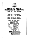
OPERATORS MANUAL
-
.
3.5KW SBCG 60Hz and 50Hz
Single Phase
GASOLINE
.
RATOH
ow Ca,bon Monoxide Emissions
/
Gasoline with an ETHANOL content
higher than 10% (E10) is not allowed
and may void warranty.
Engines & Generators
CALIFORNIA
PROPOSITION 65 WARNING
Marine diesel and gasoline engine
exhaust and some of its constituents
are known to the State of California
to cause cancer, birth defects,
and other reproductive harm.
A
WARNING:
Exhaust gasses contain Carbon Monoxide, an odorless and
colorless gas. Carbon Monoxide is poisonous and can cause
unconsciousness and death. Symptoms of Carbon Monoxide
exposure can include:
- Throbbing in Temples
- Dizziness
-Nausea
- Muscular Twitching
-Headache
- Vomiting
- Weakness and Sleepiness - Inability to Think Coherently
IF YOU OR ANYONE ELSE EXPERIENCE ANY OF THESE SYMPTOMS,
GET OUT INTO THE FRESH AIR IMMEDIATELY. If symptoms persist,
seek medical attention. Shut down the unit and do not restart
until it has been inspected and repaired.
This WARNING DECAL is provided by
WESTERBEKE and should be fixed to a
bulkhead near your engine or generator.
WESTERBEKE also recommends Installing
CARBON MONOXIDE DETECTORS in the
IIvlng/sleeplng quarters of your vessel.
They are Inexpensive and easily
obtainable at your local marine store.
Engines & Generators
SAFETY INSTRUCTIONS
INTRODUCTION
PREVENT BURNS - FIRE
Read this safety manual carefully. Most accidents are
caused by failure to follow fundamental rules and precautions. Know when dangerous conditions exist and take the
necessary precautions to protect yourself, your personnel,
and your machinery.
The following safety instructions are in compliance with
the American Boat and Yacht Council (ABYC) standards.
PREVENT ELECTRIC SHOCK
A WARNING: Fire can cause injury or death!
•
•
A WARNING: Do not touch AC electrical connections
while engine is running. Lethal voltage is present at
these connections!
•
•
Do not operate this machinery without electrical
enclosures and covers in place.
• Shut off electrical power before accessing electrical
equipment.
• Use insulated mats whenever working on electrical
equipment.
• Make sure your clothing and skin are dry, not damp
(particularly shoes) when handling electrical equipment.
• Remove wristwatch and all jewelry when working on
electrical equipment.
• Do noit connect utility shore power to vessel's AC
circuits, except through a ship-to-shore double throw
transfer switch. Damage to vessel's AC generator may
result if this procedure is not followed.
• Electrical shock results from handling a charged
capacitor. Discharge capacitor by shorting terminals
together.
•
•
PREVENT BURNS - EXPLOSION
A WARNING: Explosions from fuel vapors can cause
injury or death!
•
•
PREVENT BURNS - HOT ENGINE
•
•
A WARNING: Do not touch hot engine parts or
exhaust system components. A running engine gets
very hot!
•
Always check the engine coolant level at the coolant
recovery tank.
•
•
•
A WARNING: Steam can cause injury or death!
•
In case of an engine overheat, allow the engine to cool
before touching the engine or checking the coolant.
Prevent flash fires. Do not smoke or permit flames or
sparks to occur near the carburetor, fuel line, filter, fuel
pump, or other potential sources of spilled fuel or fuel
vapors. Use a suitable container to catch all fuel when
removing the fuel lines, fuel filters, or other fuel system
components ..
Do not opeerate with a Coast Guard Approved flame
arrester removed. Backfire can cause severe injury or
death.
Do not operate with the air cleaner/silencer removed.
Backfire can cause severe injury or death.
Do not smoke or permit flames or sparks to occur near
the fuel system. Keep the compartment and the
engine/generator clean and free of debris to minimize the
chances of fire. Wipe up all spilled fuel and engine oil.
Be aware - Diesel and gasoline will burn.
•
Follow re-fueling safety instructions. Keep the vessel's
hatches closed when fueling. Open and ventilate cabin after
fueling. Check below for fumes/vapor before running the
blower. Run the blower for four minutes before starting
your engine.
All fuel vapors are highly explosive. Use extreme care
when handling and storing fuels. Store fuel in a
well-ventilated area away from spark-producing
equipment and out of the reach of children.
Do not fill the fuel tank(s) while the engine is running.
Shut off the fuel service valve at the engine when servicing
the fuel system. Take care in catching any fuel that might
spill. DO NOT allow any smoking, open flames, or other
sources of fire near the fuel system or engine when
servicing. Ensure proper ventilation exists when servicing
the fuel system.
Do not alter or modify the fuel system.
Be sure all fuel supplies have a positive shutoff valve.
Be certain fuel line fittings are adequately tightened and
free of leaks.
Make sure a fire extinguisher is installed nearby and is
properly maintained. Be familiar with its proper use.
Extinguishers rated ABC by the NFPA are appropriate
for all applications encountered in this environment.
Engines & Generators
SAFETY INSTRUCTIONS
ACCIDENTAL STARTING
A WARNING: Carbon monoxide (CO) is a deadly gas!
A WARNING: Accidental starting can cause injury
or death!
•
To prevent accidental starting when servicing the
generator, remove the 8 amp fuse from the control panel.
•
Disconnect the battery cables before servicing the engine/
generator. Remove the negative lead first and reconnect
it last.
•
Make certain all personnel are clear of the engine before
starting.
•
Make certain all covers, guards, and hatches are
re-installed before starting the engine.
BATTERY
EXPLOSION
________________________________________- ,
~
•
Ensure that the exhaust system is adequate to expel gases
discharged from the engine. Check the exhaust system
regularly for leaks and make sure the exhaust manifolds
are securely attached and no warping exists. Pay close
attention to the manifold, water injection elbow, and
exhaust pipe nipple.
•
Be sure the unit and its surroundings are well ventilated.
•
In addition to routine inspection of the exhaust system,
install a carbon monoxide detector. Consult your boat
builder or dealer for installation of approved detectors.
•
For additional information, refer to ABYC T-22
(educational information on Carbon Monoxide).
4
A WARNING: Carbon monoxide (CO) is an invisible
A WARNING: Battery explosion can cause injury
odorless gas. Inhalation produces flu-like symptoms,
nausea or death!
or death!
•
•
•
•
Do not smoke or allow an open flame near the battery
being serviced. Lead acid batteries emit hydrogen, a
highly explosive gas, which can be ignited by electrical
arcing or by lit tobacco products. Shut off all electrical
equipment in the vicinity to prevent electrical arcing
during servicing.
Never connect the negative (-) battery cable to the
positive (+) connection terminal of the starter solenoid.
Do not test the battery condition by shorting the terminals
together. Sparks could ignite battery gases or fuel vapors.
Ventilate any compartment containing batteries to prevent
accumulation of explosive gases. To avoid sparks, do not
disturb the battery charger connections while the battery
is being charged.
Avoid contacting the terminals with tools, etc., to prevent
bums or sparks that could cause an explosion. Remove
wristwatch, rings, and any other jewelry before handling
the battery.
•
Do not use copper tubing in exhaust systems. Exhaust
sulfur causes rapid deterioration of copper tubing
resulting in exhaust/water leakage.
•
Do not install exhaust outlet where exhaust can be drawn
through portholes, vents, or air conditioners. If the engine
exhaust discharge outlet is near the waterline. water could
enter the exhaust discharge outlet and close or restrict the
flow of exhaust. Avoid overloading the craft.
•
Although diesel engine exhaust gases are not as toxic as
exhaust fumes from gasoline engines, carbon monoxide
gas is present in diesel exhaust fumes. Some of the
symptoms or signs of carbon monoxide inhalation or
poisoning are:
Vomiting
Muscular twitching
Dizziness
Intense headache
Throbbing in temples
AVOID MOVING PARTS
Always tum the battery charger off before disconnecting
the battery connections. Remove the negative lead first
and reconnect it last when disconnecting the battery.
A WARNING: Rotating parts can cause injury
or death!
BATIERY ACID
•
A WARNING: Sulfuric acid in batteries can cause
severe injury or death!
•
Weakness and sleepiness
When servicing the battery or checking the electrolyte
level, wear rubber gloves, a rubber apron, and eye
protection. Batteries contain sulfuric acid, which is
destructive. If it comes in contact with your skin, wash it
off at once with water. Acid may splash on the skin or
into the eyes inadvertently when removing electrolyte
caps.
..
Do not service the engine while it is running. If a
situation arises in which it is absolutely necessary to
make operating adjustments, use extreme care to avoid
touching moving parts and hot exhaust system
components.
Engines & Generators
II
SAFETY INSTRUCTIONS
ABYC, NFPA AND USCG PUBLICATIONS FOR
INSTALLING DIESEL ENGINES
•
Do not wear loose clothing or jewelry when servicing
equipment; tie back long hair and avoid wearing loose
jackets, shirts, sleeves, rings, necklaces or bracelets that
could be caught in moving parts.
• Make sure all attaching hardware is properly tightened.
Keep protective shields and guards in their respective
places at all times.
• Do not check fluid levels or the drive belt's tension while
the engine is operating.
• Stay clear of the drive shaft and the transmission coupling
when the engine is running; hair and clothing can easily
be caught in these rotating parts.
Read the following ABYC, NFPA and USCG publications
for safety codes and standards. Follow their recommendations when installing your engine.
ABYC (American Boat and Yacht Council)
"Safety Standards for Small Craft"
Order from:
ABYC
3069 Solomon's Island Rd.
Edgewater, MD 21037
NFPA (National Fire Protection Association)
"Fire Protection Standard for Motor Craft"
Order from:
NFPA
11 Tracy Drive
Avon Industrial Park
Avon, MA 02322
USCG (United States Coast Guard)
"USCG 33CFR183"
Order from:
U.S. Government Printing Office
Washington, D.C. 20404
HAZARDOUS NOISE
A WARNING: High noise levels can cause hearing
loss!
•
•
•
Never operate an engine without its muffler installed.
Do not run an engine with the air intake (silencer)
removed.
Do not run engines for long periods with their enclosures
open.
A WARNING: Do not work on machinery when you are
mentally or physically incapacitated by fatigue!
OPERATORS MANUAL
Many of the preceding safety tips and warnings are repeated
in your Operators Manual along with other cautions and
notes to highlight critical information. Read your manual
carefully, maintain your equipment, and follow all safety
procedures.
GASOLINE ENGINE AND GENERATOR INSTALLATIONS
Preparations to install a gasoline engine or generator should
begin with a thorough examination of the American Boat and
Yacht Council's (ABYC) standards. These standards are from
a combination of sources including the USCG and the NFPA.
Sections of the ABYC standards of particular interest are:
H-2 Ventilation
H-24 Gasoline Fuel Systems
P-I Exhaust Systems
P-4 Inboard Engines
E-9 DC Electrical Systems
All installations must comply with the Federal Code of
Regulations (FCR).
Engines & Generators
iii
CARBON MONOXIDE "CO"I LOW-CO· GENERATORS
IMPORTANT INFORMATION
DESCRIPTION
In a closed space, such as the engine compartment, the boat,
or underneath a stem swim platform, concentrations will
potentially rise to the undiluted level emanating from the
exhaust system due to a lack of fresh air to dilute the exhaust
gas. Therefore, one should never rely on dilution of the
exhaust to provide a margin of safety.
Carbon monoxide "CO" is a component of engine exhaust. It
is a colorless, tasteless, odorless, lighter than air poisonous
gas that can kill you without any warning. CO poisoning is
one of the major safety risks associated with boating. It is a
threat that must not be underestimated.
Westerbeke Low-CO generators are designed to dramatically_
reduce normal levels of CO in the engine exhaust.
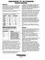
Several standards for CO have been published, expressed in
parts per miliion "ppm" and hours of exposure:
Regulator
EPA
ACGW
EPA
NIOSH
OSHA
ACGm
NIOSH
NIOSH
CO ppm
Exposure Hours
9
8
8
25
35
35
50
125
200
1200
. Westerbeke Low-CO generators achieve reduction of typical
CO by precise control of the engine's air/fuel ratio coupled
with-after treatment of the exhaust in a special catalyst. CO
emissions are not the sa~e for every model because each
engine is different. Also, certain fuel system components
are .c.ommonized across several engine models being
ad~quate for some and extra adequate for others, thus
producing different CO levels for different models.
The fuel system which accomplishes the required precise
air/fuel ratio control is comprised of many different
components: purc~ased sub-assemblies, machined castings,
sensors, electronics 'and others. Because of the extreme level
of CO reduction, any variability in the functioning of any
these components can and will cause variability of the CO
output.
CO concentration also varies with load. Usually, but not
always, the worst case CO concentration occurs at maximum
load.
1
8
8
0.5
0.0
0.0
(IDLH)
1200 ppm is the so-called IDLH concentration-
IMMEDIATELY' DANGEROUS TO LIFE AND HEALTH.
INSPECTION
.A city in California characterizes the effect of CO ,
concentration this way:
The catalyst is critical to optimizing CO levels. Any water
intrusion into the engine's exhaust system will likely quickly
compromise the proper operation of the catalyst.
Westerbeke'snd exhaust system installation instructions dated
May 2004 2 Edition must be adhered to.
NOTE: Water intrusion is not a product defect and is not
covered under warranty, neither Westerbeke s normal
product warranty nor the emissions .specific warranty
mandated by various regulating authorities such as EPA
andCARB.
Maintenance of any components affecting the flow of air into
the engine or the flow of fuel to the engine is critically
important. Fuel filters, air filters, flame arrester screens
MUST be properly maintained.
Inspection of the catalyst at the prescribed intervals is
critically important. The exhaust elbow is removed by
loosening the metal clamp to provide a view of the output
surface of the catalyst. Any visual irregularity of the nonnal
flush, honeycomb appear~ce is most likely a result of water
intrusion. The cause of the irregularity must be identified and
addressed. If there is irregularity, the catalyst and sealing
gasket must be replaced. The water injected exhaust elbow
casting must be inspected also for corrosion and replaced as
needed. Upon careful reassembly of the catalyst, new sealing
gasket, and exhau~t elbow, check for the presence of CO
while the engine is running. This must be performed with a
CO analyzer.
Parts per Million
25
100
200
Responses
Permissible exposure level, no
apparent toxic symptoms.
No poisoning for long period.
Allowable for several hours.
Should not be exposed above
this level for any period of
time. A possible mild frontal
headache in two to three hours.
Even though Westerbeke Low-CO generators are designed
to reduce normal levels of CO in the engine exhaust
dramatically, an exhaust leak of untreated exhaust would be
extremely dangerous. For this reason it is extremely important
to install a CO detector near the generatoP--afld to be sure it is
always turned ON and FUNCTIONING properly. If this
d~tector sounds, do not turn it off, assuming it is a false signal.
You can not taste, smell, or otherwise detect CO. Leave the
::(lefector on, turn off all engines and generators, evacuate the
boat leaving ports and hatches open, and seek professional
h~lp.
As soon as CO leaves the exhaust outlet, the level is subject
to dilution in the open air. The closer a person is to the
exhaust outlet, the higher the concentration of CO.
Engines & Generators
IV
EMISSIONS
This genset meets the requirements of California's Exhaust
Emissions Standards as stated on the nameplate.
You should carefully review operator (Owner) Installation
and other manuals and information you receive with your
genset. If you are unsure that the installation, use,
maintenance or service of your genset is authorized, you
should seek assistance from an approved WESTERBEKE
dealer.
California users of this genset should be aware that
unauthorized modifications or replacement of fuel, exhaust,
air 'intake, or speed control system components that affect
engine emissions are prohibited. Unauthorized modification,
removal or replacement of the engine label is prohibited.
California genset users may use the table below as an aid in
locating information related to the California Air Resources
Board requirements for emissions control.
Federal Emissions Compliance Period: The Federal
Emissions Compliance Period referred to on the nameplate
indicates the number of operating hours for which the engine
has been shown to meet Federal Emissions requirements.
Catagory C= 250 hrs, B=500 hrs,
A =1000.hrs.
EMISSIONS CONTROL INFORMATION TABLE
Emissions Warranty Information
The California emissions control walTanty statement is located in the same
packet, if information as this manual when the genset is shipped from the
factory.
Engine Fuel Requirements
The engine is certified to operate on unleaded gasoline. See FUEL
RECOMMENDATIONS.
Engine Valve Adjustment
See MAINTENANCE SCHEDULE.
Engine Ignition Timing
See MAINTENANCE SCHEDULE.
Engine Lubricating Oil Requirements
See ENGINE OIL RECOMMENDATIONS.
Engine Adjustments
ECU.
Engine Emission Contol System
The engine emission control system consists of engine design and precision
manufacture.
Catalyst
See MAINTENANCE SCHEDULE.
Oxygen Sensor
See MAINTENANCE SCHEDULE.
Back Pressure
See MAINTENANCE SCHEDULE.
Engines & Generators
v
CARBON MONOXIDE "CO"I LOW-CO GENERATORS
IMPORTANT INFORMATION
Whenever taking the time to verify proper co levels from the
exhaust with a co analyzer, always take theopportunity to
use the analyzer to "sniff' around the engine looking for CO
from exhaust leaks. Pay close attention to the connection of
the cylinder block to the sump plate, the sump plated to the
water injected exhaust elbow casting and all subsequent
downstream exhaust components and hoses and connection
points. Remember, exhaust gas that has not yet passed
through the catalyst is raw exhaust, untreated exhaust gas and
is very high in co content.
Catalyst performance will degrade over time. As the
generator accumulates operating hours, CO concentrations
will increase. The catalyst must be replaced every 2,000
hours of engine operation.
Verification of satisfactory CO levels must be done
seasonally or each 500 hours (which ever occurs first).
Verification involves actual sampling of exhaust gas with an
appropriate CO analyzer.
There are two locations where exhaust gas can be sampled.
Dry, but hot, exhaust gas can be sampled at the 1I8NPT
plugged opening on the top of the water injected exhaust
elbow's casting. Measurements at this location may not be
practical in all instances due to the high exhaust temperature,
temperature limits of the analyzer, safety concerns over
temperatures involved or the possibility of high levels of CO.
The other location is the boat's exhaust outlet, which .
contains entrained cooling water (except dry stack exhaust
systems). Only analyzers with probes should be used at this
location and it is critical that the probe not ingest water.
Probe-type analyzers have an air pump drawing a gas sample
through the probe. As a result, they tend to ingest water when
it is present. Be sure to aim the probe downwards with the
opening pointed in the direction of the water flow and just
out of the flow. Position the analyzer as high as possible with
the tubing leading to the probe running continuously downhill. Observe the usually translucent tubing between the
probe and the analyzer and be sure no water is being
ingested. If any water is ingested into the analyzer, it must be
repaired or replaced and recalibrated.
Analyzers usually require periodic calibration. Follow the
instructions that come with the analyzer very carefully
regarding calibration.
The following are manufacturers that offer CO analyzers:
Extech, TIP, Testo, TSI, Bacharach, Fluke, Monoxor, Fyrite,
Zellwgwer Analytics, Industrial Scientific Corp, GFG, TPI,
Teledyne and others. Westerbeke recommends analyzers with
a probe connected to the' analyzer by a length of transparent
tubing. They are slightly more expensive than those with the
sensor built into one end of the analyzer, but they allow you
to sample the exhaust coming out of the boat's exhaust outlet.
When measuring CO at the exhaust outlet be aware of the
ambient CO level by also measuring CO away from and
upwind of the exhaust outlet, especially in marinas. the CO
level at the exhaust will be influenced upwards by the
ambient level.
For changing the exhaust catalyst and measuring the
exhaust back pressure, refer to the Table of Contents.
Engines & Generators
vi
INSTALLATION
When installing WESTERBEKE engines and generators it is important that strict
attention be paid to the following information:
CODES AND REGULATIONS
Strict federal regulations, ABYC guidelines, and safety codes must be complied with
when installing engines and generators in a marine environment.
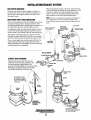
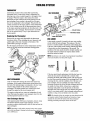
SIPHON-BREAK
For installations where the exhaust manifold/water injected exhaust elbow is close to
or will be below the vessel's waterline, provisions must be made to install a siphonbreak: in the raw water supply hose to the exhaust elbow. This hose must be looped a
minimum of 20" above the vessel's waterline. Failure to use a siphon-break when
the exhaust manifold injection port is at or below the load waterline will result in
raw water damage to the engine and possible flooding of the boat.
If you have any doubt about the position of the water-injected exhaust elbow relative
to the vessel's waterline under the vessel's various operating conditions, install a
siphon-break.
NOTE: A siphon-break requires periodic inspection and cleaning to ensure proper
operation. Failure to properly maintain a siphon-break can result in catastrophic
engine damage. Consult the siphon-break manufacturer for proper maintenance.
EXHAUST SYSTEM
The exhaust system's hose MUST be certified for marine use. Corrugated Marine
Exhaust Hose is recommended. The use of this type of hose allows for extreme bends
and turns without the need of additiinal fitting and clamps to accomplish these bends
and turns .In this regard, a single length of corrugated exhaust hose can be used. The
system MUST be designed to prevent the entry of water into the exhaust system
under any sea conditions and at any angle of vessels heal.
A detailed Marine Installation Manual covering gasoline and diesel,
engines and generators, is supplied with each unit. Apdf is available
to download from our website at www.westerbeke.com.
Engines & Generators
AVAILABLE fF\OM
YOUR WESTERBEKE
DEALER
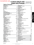
TABLE OF CONTENTS
Parts Identification ... .................................................2
Introduction ................................................................3
Installation ..................................................................5
Shore Power Transfer Switch ...................................19
Engine Components ..................................................20
Spark Plugs ............................................................ 20
Cam Sensor ............................................................ 20
Air Screen .............................................................. 20
ECU ....................................................................... 20
Engine Adjustments ..................................................21
Adjusting the Drive Belt ...................................... 21
Oil Pressure ........................................................... 21
Engine Compression Test ...................................... 22
Remote Oil Filter ................................................... 22
Water Pump Belt ................................................... 22
Valve Clearance ..................................................... 23
Replacing the Timing Belt.. .................................. .24
Bleeding the Fuel System ........................................25
Rigging and Lifting ................................................. 5
Location and Mounting ........................................... 5
Raw Water Discharge .............................................. 6
Raw Water Supply Hose .......................................... 6
Measuring Back Pressure ..........................................6
Changing Catalyst ......................................................6
Fuel, Engine Oil, and Engine Coolant.. ......................7
Control Panels - Starting/Stopping Procedure .......... 8
Remote Panel ........................................................... 8
Preparations for Initial Start-Up ................................9
Pre-Start Inspection ................................................. 9
Initial Priming the Fuel System .. ............................. 10
Safety Shutdown Switches .......................................11
Maintenance Schedule ............................................. 12
Engine Lubricating 0i1.. ............................................ 14
Changing the Oil Filter .......................................... 14
Fuel System .............................................................. 15
Changing the Fuel Filter.. ...................................... 15
Fuel Pump .............................................................. 15
Inlet Fuel Filter ...................................................... 15
Cooling System ......................................................... 16
Changing Coolant .................................................. 16
Thermostat ............................................................. 17
Heat Exchanger ..................................................... 17
Water Pumps .......................................................... 18
Water Intake Strainer ............................................. 18
DC Circuit/Battery ..................................................... 19
Raw Water Pump (Exploded View) ............................ 26
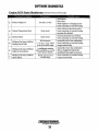
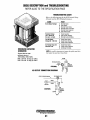
Engine Troubleshooting ............................................28
Software Diagnostics ............................................. 30
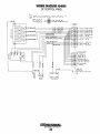
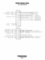
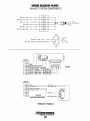
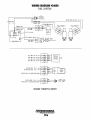
Wiring Diagrams
DC Control Panel .................................................. 36
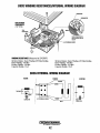
ECU Components .................................................. 37
Engine Block Components .................................... 38
Exhaust System Components ................................ 39
Generator Information ............................................. .40
BCG Troubleshooting ................................................41
SBCG Internal Wiring Diagram ................................ .42
Lay-Up and Recommissioning ..................................43
Generator Specifications ......................................... .44
Metric Conversions ................................................. .45
Suggested Spare Parts ............................................ .46
Engines & Generators
1
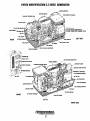
PARTS IDENTIFICATION 3.5 SBCG GENERATOR
STEPPER MOTOR
under this cover
K1-K2-K3-RELAYSfTIMER MODULE
EXTERNAL CONNECTION TERMINAL STRIP
DC VOLTAGE REGUL,A'~;l:::';;~~~
LEFT SIDE
MODULE
REAR
~'W'-f-. HOURMETER
FAULT LED'S
VOLTAGE REGULATOR
,e:;~!J..o.I.stARTISTOP SWITCH
CIRCUIT BREAKER
,ExtIAUl)T TEMP. SWITCH
C MAlNJlREAKER
rrII.~'--~"L
DRAIN HOSE
HEAT EXCHANGER
IGNITION MODUL,E
OIL PRESSURE SWITCH
MOTOR
FRONT
AC CIRCUIT BREAKEI~"
RIGHT SIDE
Engines & Generators
2
INTRODUCTION
These high performance marine engines are products of
WESTERBEKE's long years of experience and advanced
technology. We take great pride in the superior durability and
dependable performance of our engines and generators.
Thank you for selecting WESTERBEKE.
SERIAL NUMBER LOCATION
The engine s serial and model number are etched on a nameplate located on top of the unit (flywheel cover). The
engine's serial number is also stamped on the engine block.
In order to get the full use and benefit from your generator,
it is important that you operate and maintain it correctly.
This manual is designed to help you do this. Please read this
manual carefully and observe all the safety precautions
throughout. Should your engine require servicing, contact
your nearest WESTERBEKE dealer for assistance.
This is your operators manual. A parts catalog is also
provided and a technical manual is available from your
WESTERBEKE dealer. If you are planning to install this
equipment, contact your WESTERBEKE dealer for
WESTERBEKE'S installation manual.
ENGINE
SERIAL
NUMBER'
..
0 " LOCATED BEHIND
,.~~::
<_ ... a
WARRANTY PROCEDURES
<.
Your WESTERBEKE Warranty is included in a separate
folder. If, lifter 60 days of submitting the Warranty Registry
form you have not received a customer identification card
registering your warranty, please contact the factory in
writing with model information, including the unit's
serial number and commission date.
Customer Identification Card
IWIWESTERBEKE
I
.~
.::
THE INTAKE MANIFOLD
~'-
Take the time to 'enter this information on the illustration of
the nameplate as shown above, as this will provide a quick
reference when seeking technical information and/or ordering
parts.
The generators serial number and model number is located
on a decal on the the generator control panel. Take the time
to enter the information on the blank decal below. This will
provide a quick reference when seeking technical information and/or ordering parts.
~.
Customer Identification
MODEl _______ _
MR. WESTERBEKE OWNER
RPM __________ _
MAIN STREET
KW ___________ _
HOMETOWN, USA
Model
. i
60 HZ.
KVA __________ _
VOLTS ________ _
AMPS ________ _
Ser. #
Expires
ENG. HP ______ _
PRODUCT SOFTWARE
ENG. SER. NO.
GEN. SER. NO.
Product software, (technical data, parts lists, manuals,
brochures and catalogs), provided from sources other than
WESTERBEKE are not within WESTERBEKE's control.
WESTERBEKE CANNOT BE RESPONSIBLE FOR THE
CONTENT OF SUCH SOFTWARE, MAKES NO WARRANTIES OR REPRESENTATIONS WITH RESPECT
THERETO, INCLUDING ACCURACY, TIMELINESS OR
COMPLETENESS THEREOF AND WIll IN NO EVENT
BE LIABLE FOR ANY TYPE OF DAMAGE OR INJURY
INCURRED IN CONNECTION WITH OR ARISING OUT
OF THE FURNISHING OR USE OF SUCH SOFTWARE.
WESTERBEKE customers should keep in mind the time
span between printings of WESTERBEKE product software
and the unavoidable existence of earlier WESTERBEKE
product software. The product software provided with
WESTERBEKE products, whether from WESTERBEKE or
other suppliers, must not and cannot be relied upon exclusively as the definitive authority on the respective product.
PF IPHASE ___ _
I
WIRES ________ _
RATING _______ _
INSUL CLASS __
TEMP. RISE ___ _
BATTERY _____ _
C.I.D. _________ _
Fill in the information for your own reference. $:J]
Engines & Generators
3
INTRODUCTION
ORDERING PARTS
PROTECTING YOUR INVESTMENT
Whenever replacement parts are needed, always provide the
generator and engine model and serial numbers. In addition,
include a complete part description and part number for each
part needed (see the separately furnished Parts Catalog).
Also insist upon WESTERBEKE packaged parts because
will fit or generic parts are frequently not made to the same
specifications as original equipment.
Care at the factory during assembly and thorough testing
have resulted in a WESTERBEKE generator capable of
many thousands of hours of dependable service. However the
manufacturer cannot control how or where the generator is
installed in the vessel or the manner in which the unit is
operated and serviced in the field. This is up to the
buyer/owner-operator.
NOTES, CAUTIONS AND WARNINGS
NOTE: Seven important steps to ensure long generator life:
As this manual takes you through the operating procedures,
maintenance schedules, and troubleshooting of your
generator, critical information will be highlighted by
NOTES, CAUTIONS, and WARNINGS. An explanation
follows:
• Proper engine and generator installation.
• An efficient well-designed exhaust system that includes
an anti-siphon break to prevent water from entering t.'ie
engine.
• Changing the engine oil and oil filters every 100 operating hours.
NOTE: An operating procedure essential to note.
A
• Proper maintenance of all engine and generator components according to the maintenance schedule in this
manual.
CAUTION: Procedures. which if not strictly
observed. can result in the damage or destruction of
the engine or generator.
A
• Use clean" unleadedfuel #89 octane. No higher than E10 ethanol blend.
• Winterize your engine according to the "Lay-up and
Recommissioning" section in this manual.
WARNING: Procedures. which if not properly
UNDERSTANDING THE GASOLINE GENERATOR
followed. can result in personal injury or loss of life.
The gasoline engine driving an AC generator is in many
ways similar to a gasoline automobile engine. The cylinders
are in-line, and the engine's cylinder head has an overhead
camshaft which is belt-driven. The engine incorporates a
pressure type lubrication system, and a water-cooled engine
block.
NOTE: A carbon monoxide warning decal has been provided
by WESTERBEKE. Affix this decal in a visible location in the
engine room.
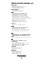
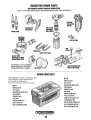
SPARES AND ACCESSORIES
Certain spare parts will be needed to support and maintain
your WESTERBEKE generator or engine when cruising (see
SUGGESTED SPARE PARTS). Often even simple items such
as proper fuel and oil filters can be difficult to obtain along
the way. WESTERBEKE will provide you with a suggested
spares and accessories brochure to assist you in preparing an
on-board inventory of the proper WESTERBEKE parts.
To a large degree, the generator's engine requires the same
preventive maintenance that is required of a gasoline
automobile engine. The most impOltant factors to the
generator's longevity are proper ventilation, maintenance of
the fuel system, ignition system, and cooling system.
CARBON MONOXIDE DETECTOR
WESTERBEKE recommends mounting a carbon monoxide
detector in the vessels living quarters. Carbon monoxide,
even in small amounts, is deadly.
The presence of carbon monoxide indicated an exhaust leak
from the engine or generator or from the exhaust
elbow/exhaust hose, or the fumes from a nearby vessel are
entering your boat.
If carbon monoxide is present, ventilate the area with clean
air and COlTect the problem immediately!
Engines & Generators
4
INSTALLATION
SIDE VIEW
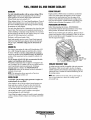
RIGGING AND LIFTING
The engine/generator is fitted with lifting eyes. Attach
wire rope or chain slings capable of supporting the
engine/generators weight to the eyes and lift the engine/generator by means of tackle attached to these slings. The lifting
eyes have been designed to carry the full weight: auxiliary
slings are not necessary.
NOTE: Rigging work is best done by someone experienced
and competent in handling machinery.
LOCATION AND MOUNTING
A solid, level mounting platform is very important for the
proper operation of your generator. Select a location that will
allow adequate space on all sides for ventilation and servicing. Locate the generator away from living quarters, and
away from bilge splash and vapors.
Refer to WESTERBEKE'S installation manual for detailed
information on installing a Marine Generator in a boat.
RAW WATER INLET O.Sin (2.7mm)
1.0. HOSE
WATER OUTLET AND DlSCHr.RGE.
HOSES O.Sln (2.7mm) 1.0.
BOTTOM VIEW
·FDUR 1/2" BOLTS
USE THE PAN AS A TEMPLATEFOR
LOCATING THE PROPER MOUNTING
HOLES TO THE PLYWOOD BASE
TOP VIEW '
3/4" PLYWOOD-BOLTED/FIBERGLASSED
IN PLACE
DIMENSION (INCHES AND MM)
DIMENSIONAL DRAWINGS
BATTERY ATTACHMENTS,
TO STARTER MOTOR
For dimensional drawings. View the drawings on the
Westerbeke website www.westerbeke.com for the most
current drawings with dimensions.
REFER TO THE WIRING
DIAGRAM IN THIS MANUAL
(-) NEGATIVE
LEAD
(+) POSITIVE
LEAD
Engines & Generators
5
INSTALLATION/EXHAUST SYSTEM
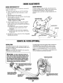
RAW WATER DISCHARGE
When the generators location is above the loaded water line
of the vessel during all attitudes of vessel operation, it is still
advisable to loop the raw water discharge hose at least 6 •
inches or more above the generator and then down to the
inlet connection on the water injected exhaust elbow.
The fresh water that flows thru the engine is cooled by a
continuous flow of raw water (via the heat exchanger). As
the raw water is discharged overboard, it is used to cool
the exhaust system.
RAW WATER SUPPLY HOSE (INSTALLING)
The raw water supply hose from the discharge conne.::tion on
the engines cooling system to the inlet connection of the
water injected exhaust elbow must be looped a minimum of
12 inches (30cm) above the vessels loaded water line. ,
On installations where the water injected exhaust is close to
or below the vessels loaded water line, provisions must be
made to install a syphon break in the raw water supply hose.
NOTE: Always use a quality hose with good wall integrity or
wire reinforced hose so it will maintain its shape when
looped and also provide proper mechanical support for the
hose.
EXHAUST ELBOW
The function of the syphon break is to stop the raw water
flow after the engine is shutdown. This flow, if not stopped,
will fill the exhaust system and possibly the engine as well.
The raw water supply hose must be looped well above the
loaded water line to allow the syphon break to function
during all attitudes of vessel operation to prevent syphoning
when the generator is not operating.
I
I
(
I
:I
HEAT EXCHANGER
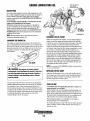
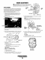
EXHAUST BACK PRESSURE
Measure back pressure after the engine has
reached its normal operating temperature and
with rated amperage output applied to the
generator (30 amps @60Hz and 15 amps @ 50Hz).
Westerbekes Installation Manual Pub. #43400
has detailed information on back pressure .
.... ~
/"
I
BACK PRESSURE SHOULD
I
NOT EXCEED 41" (102.5cm)
I
IN THE WATER COLUMN OR
EXCEED 1.5 PSI WHEN USING I
A PSI GAUGE.
WATER
COLUMN
MEASURING
EXHAUST BACK
PRESSURE
POSITION THE CLAMP DVER
THE TWO FLANGES (AND GASKET)
AND TIGHTEN SECURELY
Engines & ,Generators
6
FUEL, ENGINE OIL AND ENGINE COOLANT
GASOLINE
ENGINE COOLANT
Use only unleaded gasoline with an octane rating of 89 or
higher. Higher octane is recommended. The use of lower
octane gasoline will adversly affect engine performance.
Ethanol blends must not exceed E-lO.
When fueling, follow U.S. Coats Guard Regulations. Close all
hatches and companionways to prevent fumes from entering
the vessel. Ventilate properly after fueling and before starting
the generator or main engines.
Use only clean fresh fuel! It is important to buy clean fuel, and
keep it clean. The best fuel can be rendered unsatisfactory by
careless handling or improper storage facilities. To assure that
the fuel going into the tank for your engine's daily use is clean
and pure, the following practice is advisable:
Purchase a well-known brand of fuel.
Install and regularly service a good, Coast Guard approved
metal bowl type filter/water separator between the fuel tank
and the engine. This filter rating must be 10 microns or
smaller.
Engine coolant a 50/50 mixture of antifreeze and distilled
water. This coolant allows the engine to run at its proper
temperature by transferring heat from the engine to the
coolant. It also lubricates and protects the cooling system
from rust and corrosion. A 50/50 mixture of antifreeze and
distilled water will protect the engine to _34°P (1.12°C).
PURCHASING ANTIFREEZE
Rather than preparing the mixture, WESTERBEKE
recommends buying the premixed antifreeze so that when
adding coolant, the mixture will always be correct.
ENGINE OIL
Use a heavy duty engine oil with an API classification of SJ,
SL, or SM. Change the engine oil and filter after an" initial
50 hours of break-in operation. Thenfolrow the oil change
interval as specified in the MAINTENANCE SCHEDULE
section of this manual and not be extended if synthetic oils
are used.
An oil viscosity of SAE 15W-40 is recommended for this
engine in all conditions and all seasons.
Westerbeke Corporation does not approve or disapprove the
use of synthetic oils. If synthetic oils are use, engine break-in
must be performed using conventional oil. Oil change
intervals must be as listed in the MAINTENANCE
SCHEDULE section of this manual and not be extended if
synthetic oils are used.
NOTE: The infonnation above supersedes all previous
statements regarding synthetic oil.
COOLANT RECOVERY TANK
A coolant recovery tank kit is supplied with each generator.
The purpose of this recovery tank is to allow for engine
coolant expansion and contraction during engine operation,
without the loss of coolant and without introducing air into
the cooling system.
NOTE: This coolant recovery tank, with its short length of
OVER-FILLING
hose, is best located at or above the cooling systems
pressurelfill cap.
CAUTION: The oil sump on this generator's engine can
unintentionally be over-filled!
After shutdown, the oil in the engines internal pasages can
linger and take a number of hours to drain back into the
sump. Allow at least a few hours for the oil to settle back
into the sump before checking the dipstick reading.
(Re-starting the engine is not a problem as the engine's
internal passages are well lubricated).
Over-filling the engine's sump will result in erratic operation,
andlor a smokey oil laden exhaust, hard starting and possible
no start.
Engines & Generators
7
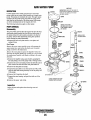
CONTROL PANEL • START/STOP PANEL
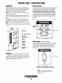
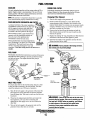
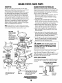
DESCRIPTION
FAILURE TO START
To Start: Press the rocker switch to the start position and
The start cycle will automatically terminate if the engine fails
to start after 8 seconds of cranking. Three start attempts can
be performed before an underspeed fault occurs. This
release. (The switch will revert to its center position). The
engine will crank and start electronically. A green LED
on the switch will indicate the engine is running.
prevents prolonged cranking which can result in the
exhaust filling with water and backing into the engine.
NOTE: There is a brief delay while the ECU self-tests before
the start button responds.
To try repeat start attempts while solving and repairing the
problem, close the thru-hull (water intake valve). When
the starting problem is corrected do not forget to open the
thru-hull.
Apply a light load to the generator and allow the engine
to wann up to operating temperature before applying heavy
loads.
To Stop: Press the rocker switch to stop and release. The
ECU will receive the signal to shut the engine down. The
green LED will go off indicating the unit has shut-down.
NOTE: This green LED may illuminate dimly when the engine
is not running. This is part of the self diagnostic circuit and is
normal.
~:'
·~f~·
. II!XT. £Un
ImIAIUI8T TRIP
OIL..IIIIJWUIIR!
_ _ "II"1I1IP
(l01.6mm)
HOURMETER
~...([
7iAI~J.--- LED DISPLAYS/FAULT LED'S
o
START/STOP
~~-1\ 1.--1---- ROCKER SWITCH
0
~----3.34"
GREEN LED
\..---Joo--f---_
.911)-
2DA CIRCUIT
BREAKER
(84.84mm)
--~
REMOTE PANEL (with Fault Display)
A remote panel is available that allows for remote operation
of the generator. The panel comes with either a 15' or 30'
plug-in extension harness. The start/stop sequence is
identical. Once installed, the engine can be operated by
either panel.
8AFUSE
PN 033769
MAIN CIRCUIT
BREAKER
SHUTDOWN (Refer to SAFETY SHUTDOWN SWITCHES)
A shutdown is when the ECru (Electronic Control Unit)
stops the generator because it has detected an operating fault
which could cause damage to the engine, the generator, or
create an unsafe operating condition.
IT.
o
o
~
2.60" «66.04mm)
3.190" (81.03 mm)
--.J
REMOTE PANEL (STOP/START SWITCH ONLY)
NOTE: For wiring these remote panels,
refer to the Wiring Diagram section
in thus manual.
Engines & Generators
8
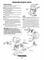
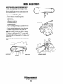
PREPARATIONS FOR INITIAL START-UP
PRESTART INSPECTION
Before starting your generator set for the first time or after a
prolonged layoff, check the following items:
•
Make certain the cooling water thru-hull petcock is open.
•
Check the engine oil level. Add oil to maintain the level at
the full mark on the dipstick.
•
Check the fuel supply and examine the fuel filter/separator
bowls for contaminants.
•
Check the DC electrical system. Inspect wire connections
and battery cable connections.
•
Check load leads for correct connection as specified in the
wiring diagrams.
•
•
Examine air inlet and outlet for air flow obstructions.
Be sure no other generator or utility power is connected to
load lines.
•
Be sure that in power systems with a neutral line that the
neutral is properly grounded (or ungrounded) as the
system requires, and that the generator neutral is properly
connected to the load neutral. In single phase systems an
incomplete or open neutral can supply the wrong line-toneutral voltage on unbalanced loads.
•
Coolant
•
Check the coolant level in both the plastic coolant
recovery tank and at the filler neck opening on the unit.
NOTE: After the initial running of the generator, the air in
the engine's cooling system should be purged to the plastic
coolant recovery tank. After shutdown and as the engine
cools, coolant should be drawn back into the engine's
cooling system to replace the displaced air. Once cooled,
open the air bleed petcock on the engine's heat exchanger
to allow any air left in that area to be expelled. Thtm close
it. Open the pressure cap on the system filler neck and
ensure the system is completely full. Replace the cap· and
fill the plastic coolant recovery tank half way between MAX
and LOW.
Visually examine the unit. Look for loose or missing parts,
disconnect wires, unattached hoses, and check threaded
connections. Make sure there·is no leakage.
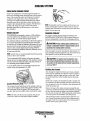
A CAUTION:. When starting the generator, it is
OIL FILL CAP
recommended that alMC loads, especially large motors,
be switched OFF until the engine has come up to speed
and starts to warm up. This precaution will prevent damage
caused by unanticipated operation of the AC machinery and
will prevent a cold engine from stalling.
(YELLOW)
r - t - - - - OIL FILTER
COOLING
WATER BY·PASS
CONNECTS
TO WATER
PUMP
INSPECT PERIODICALLY
FULL
Engines & Generators
9
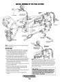
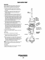
MING OF THE FUEL SYSTEM
SCHRADER
VALVE
FUEL
. MODULE
DIS_CONNECT
TO HARNESS
INLET
FILTER
FUEL
~
~,
DETACH FUEL LINE . ,
ANDFITriNG
.~
FROM SHIPS INTERNAL
FUEL SUPPLY
NOTE: The generators fuel system must be primed with fuel
·~SCHRADER
~ VALVE CAP
before its initial start.
INSTRUCTIONS
1. Connect a Snap On MT337B, OTC 7211 or equivalent
fuel bleed/pressure gauge set (available at auto supply
stores) to the schrader valve on the fuel rail at the
injectors. Direct the purge line from this tool into a
container and open the valve to the purge line.
2. Temporarily attach a seperate fuel supply hose with
Primer Bulb to the fuel inlet connection on the engine.
3. Operate the primer bulb moving fuel into the engines fuel
system. Monitor the fuel/air flow through the purge line
into the container. Once clear fuel free of air is moving
through the purge line, stop priming.
4. Remove the fuel bleed/pressure gauge set and replace the
cap on the schrader valve.
5. Remove the seperate fuel supply hose from the inlet
connection and connect the ships internal supply. Be
careful to prevent any fuel spillage.
6. Start the unit and allow the unit to warm up and load test.
Check for any fuel system leaks.
7. Re-bleed once running, low first then high pressure
schrader.
The fuel bleed/pressure gauge set c~~ be connected to
the schrader valve on the fuel module while the engine is
running with the purge line directed into a container and be
used to bleed any air that may have entered the system while
peiforming step #5. Care should be taken when opening the
valve on the purge line. It need only be opened slightly to
allow any air to escape.
NOTE:
A CAUTION: Fuel and fuel vapors are explosive! Do
not allow any smoking, open flames or other source of
fire near the fuel system. be certain that fuel lines are
tight and free of leaks. Wipe up any spilled fuel and
properly dispose of soiled rags.
I ""fIY'IWESTERBEKE
I
Engines & Generators
10
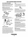
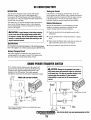
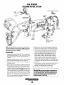
SAFETY SHUTDOWN SENSORS AND SWITCHES
SAFETY SHUTDOWN SWITCH/SENSORS
Fuses
The engine is protected by four automatic shutdown circuits.
Should a shutdown occur, do not attempt to restart without
finding and correcting the cause. Refer to the heading
Engine starts, runs and then shuts down in the ENGINE
TROUBLESHOOTING section of this manual.
The following is a description of these automatic shutdown
circuits:
A FL-8A fuse located on the control panel protects the electrical wiring. If an amperage overload occurs, the fuse will
blow and shut the engine down.
A 20A ATM fuse protects the battery charging circuit. If this
fuse fails, the engine will continue to run but the battery will
not be charging.
~
~
High Exhaust Temperature Switch
ATM 20AFUSE
An exhaust temperature switch is located on the water
injected exhaust elbow. Normally closed contacts, this switch
will open and the ECU will interpret this as a high exhaust
temperature issue and de-energize the K2 and K3 relays,
stopping the generator.
Oil Pressure Sensor
An oil pressure sensor is located off the engines oil gallery.
Oil pressure on the sensor affects the DC voltage through the
sensor to the ECU. Should the voltage reach a preset value,
the ECU will interpret this as a low oil pressure issue and
open the K2 run relay, stopping the generator. The oil
pressure LED on the panel will illuminate.
. EXHAUST ElBOW
Main AC Circuit Breaker
The main circuit breaker at the control panel will
automatically disconnect the AC power if there is an
overload. This circuit breaker must be manually switched off
when servicing the engine/generator.
Oil Pressure Switch
The oil pressure switch sensors the engine's oil pressure. If
the oil pressure falls below 5 PSI, the switch will shut off the
fuel pump and the engine will shut down. Thw switch will
reset itself when the oil pressure is restored.
20ACIRCUIT
iBREAKER
'--=-l~- SA
FUSE
Water Temperature Sensor
A water temperature sensor is located at the thermostat
housing. This resistance of the sensor changes as a function
of temperature. The ECU measures this resistance and
converts it to the corresponding engine coolant temperature.
When the coolant temperature reaches the warning threshold,
the CHECK ENGINE LED on the panel illuminates. If the
coolant temperature exceeds the shut-down threshold, the
ECU will open the K2 and K3 relays shutting down the
generator and the coolant temperature LED on the panel will
illuminate.
. MAIN AC CIRCUIT
BREAKER
Engine DC Circuit Breaker
The generator's engine DC circuit is protected by a rocker
type DC 20 amp breaker mounted on the control box. This
also serves as an Emergency Stop Switch. Excessive DC
current draw or DC electrical overload anywhere in the
instrument panel wiring or engine wiring will cause the
breaker to trip to the OFF position. In this event, the DC
power to the ECU will be interrupted, stopping the generator.
No panel LED will illuminate. Check and repair the source
of the problem. After repairing the fault, reset the breaker and
restart the generator. The DC breaker must be cycled OFF
then ON to clear any ECU shutdown from the ECU after the
fault situation has been repaired.
High/Low RPM Shutdown
The ECU monitors engine rpm via the MPU )Magnetic PickUp) that is mounted under the flywheel. When the engine
speed falls or rises to a pre-set rpm level, the ECU will shut
down the engine and the fault LED for speed will illuminate.
Engines & Generators
11
MAINTENANCE SCHEDULE
A WARNING: Never attempt to perform any service while the engine is running. Wear the proper safety equipment such as goggles
and gloves, and use the correct tools for each job. When servicing/replacing DC components, turn off the 20 amp DC circuit breaker on
the control panel, or disconnect the battery terminals.
SCHEDULED MAINTENANCE
EXPLANATION OF SCHEDULED MAINTENANCE
I DAilY CHECK BEFORE START-UP
Coolant Level
Check at recovery tank, if empty, check at manifold. Add coolant if needed.
Engine Oil Level
Fuel/Water Separator (owner installed)
Oil level should indicate between MAX. and LOW on dipstick. Do not overfill!
Check for water and dirt in fuel. Drain filter if necessary. Replace filter per
manufacturer's recommendation
Fuel Supply
Visual Inspection of Engine
Fresh unleaded gasoline with an octane rating of 89 or higher.
Check for fuel, oil and water and exhaust leaks. Check for rust or corrosion. Inspect
wiring and electrical connections. Ensure that bolts & nuts tight. Surface of the engine
shoulkd be kept clean
IINITIAL 50 HOURS OF OPERATION
Valve Clearance
Generator Drive Belt
Initial Adjustment.
. Measure spring tension, inspect belt condition. Adjust tension as needed.
IINITIAL 50 HOURS OF OPERATION
Engine Oil and Filter
Exhaust System
• Initial engine oil and filter change at 50 hours, then change both every 100 hours.
Initial check at 50 hours, then every 250 hours. Carefully inspect for leaks. Check
anti-siphon valve operation. Check the exhaust elbow for carbon and/or corrosion
buildup on inside passages; clean and replace as necessary.
Zinc Anode
Inspect/clean
Fuel Filter
Initial change.
Fuel Inlet Filter
Initial change.
Spark Plugs
Check gap (0.035 in/0.8-0.9 mm)
Flame Arrester Screen
Initial cleaning of screen.
IEVERY 50 OPERATING HOURS OR WEEKLY
Drive Belts (Water Pump)
Inspect for proper tension (3/8" to 1/2" deflection) and adjust if needed. Check belt
for Slipping, cracking and wear. Adjust tension or replace as needed.
Starting Batteries (and House Batteries)
Check electrolyte levels Make sure cables and connections are in good order. Clean
off corrosion if needed. Apply petroleum jelly to terminals for corrosion protection .
. Fuel Pump
Inspect for leaks, ensure fuel and electrical connections are clean and tight.
NOTE: Work out your own schedule, boats location, use of shore power can make
a difference. Inspect monthly to determine schedule.
Zinc Anode
I EVERY 100 OPERATING HOURS OR YEARLY
Engine Oil and Filter
Change engine oil and filter.
Flame Arrester Screen
Clean screen, inspect rubber sealing ring and replace if necessary.
I EVERY 250 OPERATING HOURS OR YEARLY
Valve Clearance
Adjust valves.
Generator
Wipe generator clean of dust and engine exhaust Remove vent cover and inspect for loose
connections and overheated wires or windings. make certain vents are clear and
unobstructed.
Timing Belt
Inspect/replace if needed.
Engines & Generators
. ,.
12
MAINTENANCE SCHEDULE
SCHEDULED MAINTENANCE
EXPLANATION OF SCHEDULED MAINTENANCE
EVERY 250 OPERATING HOURS OR YEARLY (cant.)
'Exhaust CO Level
Sample exhaust with CO analyzer.
·Exhaust Elbow
Test exhaust elbow for structural integrity. Replace if elbow is corroded or deteriorated.
Always use a new gasket. NOTE: A leaking exhaust elbow or gasket can cause carbon
monoxide exposure!
Exhaust System
Carefully inspect for leaks. Check anti-siphon valve operation. Check the exhaust elbow
for carbon and/or corrosion build -up on inside passages. Clean and replace as necessary.
·Exhaust System Back Pressure
Perform back pressure test to ensure system has not developed restrictions that will
increase pressure above 1.5 psi or 41 inches of water column at full operating amperage
load. Correct as needed.
Fuel Filter and O-Rings
Remove antr replace fuel filter and all sealing O-rings.
Fuel Filter Inlet
Remove and replace inlet fuel filter.
Generator
Check that AC connections are clean and secure. Ensure wires have no chafing.
See GENERATOR INFORMATION.
Hoses
Spark Plugs
Engine hoses should be firm and tight. Replace if hoses become spongy, brittle or
delaminated. Check and tighten all hose clamps.
Replace spark plugs.
Vibration Isolators/Engine Mounts
Check vibration isolators, brackets and mounting hardware.
Zinc Anode
Remove and replace zinc anode. Open heat exchanger end cap(s) and clean out debris.
Replace gasket and O-rings if needed.
I EVERY 500 OPERATING HOURS OR YEARLY
Raw Water Pump
Remove the dual pumps. Follow the instructions in this manual and disassemble both pumps.
Inspect and replace any worn parts. Lubricate, reassemble and install. With engine running,
check for leaks and for proper pumping action.
EVERY 500 OPERATING HOURS OR EVERY TWO YEARS
Coolant System
Drain, flush and re-fill the cooling system with appropriate antifreeze mix. Replace
the thermostat and coolant pressure cap.
Engine Compression, Head Bolt Torgue and
Valve Clearances
Incorrect valve clearance will result in poor engine performance. Check the head
bolt torque and adjust the valve clearances. Check that the compression pressure is
within published specifications.
Starter Motor
Check solenoid and motor for corrosion. Remove and lubricate. Clean and lubricate the starter
motor pinion drive.
Diverter Valve
Replace.
I EVERY 1000 OPERATING HOURS OR EVERY FOUR YEARS
'Engine Timing Belt
Heat Exchanger
Remove and replace the timing belt. NOTE: Failure to replace the timing belt at the
recommended interval could result in timing belt failure resulting in major damage
to the engine.
Remove the heat exchanger for professional cleaning and pressure testing.
I EVERY 2000 OPERATING HOURS
·Oxygen Sensor
Remove and replace exhaust oxygen sensor. Inspect every 1,000 hours.
·Catalyst
Remove and replace exhaust catalyst.
*WESTERBEKE recommends this service
be performed by an authorized mechanic.
NOTE: The operation of the unit's "SAFE CO" system must
be monitored at least once an operating season. This is to
ensure that the system is operating properly. Free system
diagnostic software is available for use with a laptop by
contacting your area Westerbeke Distributor.
Em:zines & Generators
13
ENGINE LUBRICATING OIL
DESCRIPTION
Use a heavy duty engine oil with an API classification of SJ,
SL, or SM. Change the engine oil and filter after an initial 50
hours of break-in operation. Then follow the oil change
'
interval as specified in the MAINTENANCE SCHEDULE
in this manual.
An oil viscosity of SAE-15W-40 is recommended for this
engine in all conditions, and all seasons.
Westerbeke Corporation does not approve or disapprove
the use of synthetic oils. If synthetic oils are used, engine
break-in must be performed using conventional oil. Oil
change intervals must be as listed in the MAINTENANCE
SCHEDULE section of ibis manual and not be extended if
synthetic oils are used. '
NOTE: The information above supersedes all previous
statements regarding synthetic oil.
CHANGING THE ENGINE OIL
The engine oil should be warm. Remove the oil drain hose
from its attachment bracket and lower it into a container and
allow the oil to drain, or attach a pump to the end of the drain
hose and pump the old oil out. Make sure the oil drain hose
is properly secured in its holder after all of the old Qil has
d
been dr'
rune.
~':''''::~""!""".,,,'i.
SPIN-ON
. OIL FILTER
PN#048078
I;;nll.111:11111:1
THE OIL FILTER
When removing the used oil filter, you may find it helpful to
ipunch a hole in the upper and lower portion of the old filter
to drain the oil into a container before removing it. This helps
to lessen spillage. An automotive filter wrench ~hould be
helpful in removing the old oil filter. Place some paper towels
and a plastic bag around the filter when unscrewing it to catch
any oil that's in the filter. Inspect the old oil filter as it is
removed to make sure that the rubber sealing gasket comes
. off with the old oil filter. If this rubber sealing gasket remains
sealed against the oil filter adapter, gently remove it. When
installing the new oil filter element, wipe the filter gasket's
sealing surface on the oil filter adapter free of oil and apply a
thin coat of clean engine oil to the rubber sealing gasket on
the oil filter. Screw the filter onto the threaded oil filter stub,
and tighten the filter firmly by hand.
NOTE: Use genuine WESTERBEKE oil filters. Genericfilters
are not recommended. '
A WARNING: Used engine oil contains harmful
REFILLING THE OIL SUMP
contaminants. Avoid prolonged skin contact. Clean skin
and nails thllroughly using soap and water. Launder or
discard clothing or rags containing used oil. Discard
used oil properly.
Add fresh oil through the valve cover. After refilling the oil,
run the engine for a few moments while checking the engine's
oil pressure. Make sure there is no leakage around the new
oil filter or from the oil drain system.
Always observe the old oil as it is removed. A yellow/gray
emulsion indicates the presence of water in the oil. Although
this condition is rare, it does require prompt attention to
prevent serious damage. Call a competent mechanic if water
is present in the oil. Water present in the oil can be the result
of a fault in the exhaust system attached to the engine and/or
a siphoning through the water cooling circuit into the .
exhaust, filling it up into the engine.
OVER-FILLING
CAUTION: The oil sump on this generator's engine can
unintentionally be over-filled!
After shutdown, the oil in the engines internal passages can
linger and take a number of hours to drain back into the oil
sump. Allow at least a few hours for the oil to settle back into
the sump before checking the dipstick. An overnight period
will provide an even more accurate dipstick reading.
(Re-starting the engine is not a problem as the engine's
internal passages are well lubricated).
Over-filling the engine's sump will result in erratic operation,
and/or a smokey white oil laden exhaust, hard starting and
possible no start.
Engines & Generators
14
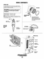
FUEL SYSTEM
GASOLINE
ENGINE FUEL FILTER
Use only unleaded gasoline with an octane rating of 89 or
higher. Higher octane is recommended. The use of lower
octane gasoline will affect engine performance adversely.
Ethanol blend must not exceed E 1o.
Periodically check the fuel connections and the bowl for
leakage. Replace the filter element after the first 50 hours
then follow the MAINTENANCE SCHEDULE.
Changing Filter Element
NOTE: The generator compartment should have a gasoline
fume detector/alarm properly installed and working.
1. Shut the fuel sUDply to the generator off.
2. Ensure system fuel pressure is at zero. Bleed off the
system pressure using a Schrader valve located on the
injector throttle body. Use extreme care as pressure maybe
as high as 45 PSI or more. Use towels to wrap the valve
and catch or subdue any fuel spray.
3. Unscrew the fuel bowl from the housing and pull the
filter element down and off. Use care to catch any fuel
that may be present.
GASOLlNEJWATER SEPARATOR AND
A primary fuel filter of the water separating
type must be installed between the fuel tank
and the engine to remove water and oth,er
contaminant's from the fuel before they can
be carried to the fuel system on the engine.
Most installers include a type of filter/water.
separator with the installation package as
they are aware of the problems that
contaminant's in the fuel can cause.
4. Replace the sealing "0" ring. Install the new filter element
and thread on the fuel bowl then tighten by hand.
5. Open the fuel supply to the generator and start the unit.
Ensure that there are no leaks.
These gasoline filters must have metal bowls
(not "Set;-through") to meet U.s. Coats Guard TYPICAL FUEL
FILTER/WATER
requirements. The metal bowls have drain
, SEPARATOR
valves to use when ctJ,eckiI).g (or water and
impurities. This fIlter rating must be iOmicrons or
smaller.
.
A WARNING: Fuel is present in the hosing and lines.
Use extreme care toprevent"spiUage
FUEL PUMP
Periodically ch~k the fuel conriections to and out of the pump
and make sure that 'no leakage is present and that the fittings
are tight and secUre. The engine mounted fuel pump is
maintenance free.
FUEL LIFT PUMP
PN#045354
ENGINE
FUEL
FILTER·
FUEL
MODULE
LUBRICATE WITI;I
CLEAN FUEL AND
PRESS THE FILTER
.ON OVER THE. a-RING
PRE·FILL
WITH FRESH FUEL,
INLET FUEL FILTER
To ensure clean fuel into the fuel lift pump, there is a small
in-line fuel filter connected to the fuel module. This filter
should be replaced every 250 hours of operation.
1. Shut off the fuel supply to the generator. Disconnect the
fuel supply line to thdnlet filter and unscrew the filter
from the pump inlet. Take care to catch any fuel that may
be present.
AWARNING: Shut otr the'tuel valve at the tank when
2. Thread on the replacement inlet filter and connect the
fuel supply line. Use care when connecting and
tightening the fuel supply line so as not to distort the
inlet filter.
3. Tum on the fuel supply to the generator and start the
generator. Ensure that there are no leaks.
servicing the fuel system. Take care in catching any fuel
that may spill. DO NOT allow any smoking, open flames
Dr other sources of fire near the fuel system when
serviCing. Ensur" proper ventilation exists when
servicing the fuel system.
Engines & Generators
15
COOLING SYSTEM
FRESH WATER COOLING CIRCUIT
Fresh water (antifreeze) is moved through the engine by a
belt driven circulating pump, absorbing heat from the engine.
Some of the coolant by-passes the thermostat to maintain
circulation in the engine and is drawn through the heat
exchanger. The engine operating temperature rises and the
thermostat reacts to this and starts to open allowing more
coolant to flow through the heat exchanger. The thermostat
opening will change as it gains control of the engine
operating tymperature by allowing more or less coolant
flow through it.
NOTE: Periodically check the conditiQn of the pressure cap.
Ensure that rhe upper and lower rubber seals are in good
condition and check that the vacuum valve opens and closes
tightly. Carry a spare cap.
ENGINE COOLANT
CHANGING COOLANT
WESTERBEKE recommends a mixture of 50% antifreeze
and 50% distilled water. Distilled water is free from the
chemicals that can corrode internal engine surfaces.
The antifreeze performs a double duty. It allows the engine to
run at proper temperatures by transferring heat away from
the engine to the coolant and lubricates and protects the cook
ing circuit from rust and corrosiol1. Look for a good quality
. antifreeze that contains Supplemental Cooling Additives
(SCAs) that keep the antifreeze chemically balanced, crucial
to long term protection.
The engine's coolant must be changed according to the
MAINTENANCE SCHEDULE. If the coolant is allowed to
become contaminated, it can lead to overheating problems.
NOTE: Look for the new environmentally friendly long lasting
antifreeze that is now available.
A CAUTION: PrDper cooling system maintenance is
critical; a substantial number of engine failures can be
traced back to cooling system corrosion.
Drain the engine coolant by loosening the drain plug on the
heat exchanger and opel1ing pressure cap. Also loosen the air
bleed petcock on the top of the heat exchanger
A CAUTION: The engine must be allowed to cool
The recommended 50/50 mixture will protect the engine
against the most extreme temperature. The antifreeze miXture
will also retard rust within the engine and add to the life of
the circulating pump impeller and seals.
A proper 50/50 mixture as recommended will protect the
engine coolant to temperatures of - 4O"F.
down before attempting these procedures. Not only is
the surface of the engine hot but coolant temperatures
can be at 190 0 F.
Refilling the Coolant
The coolant recovery tank allows for the expansion and contraction of the engines coolant during engine operation without introducing air into the system. This recovery tank is
provided anomust be installed oefore operating the engine.
NOTE: 171is tank, with its sltort run oJ plastIC hose, is best
located at or above the level of the engine:r manifold.
After closing the engine block drain, pour clean, premixed
coolant into the manifold and when the coolant is visible in
the manifold, start the engine and run it at slow idle. Open
the air bleed petcocks on the manifold and the thermostat
housing.
Monitor the coolant in the manifold and add as needed. Fill
the manifold to the filler neck and when the coolant flowing
from the petcock is free of air bubbles, clo.se the petcock and
install the pressure cap.
Remove the cap on the coolant recovery tank and fill with
coolant mix to halfway between LOW and MAX and replace
the cap. Run the engine and observe the coolant expansion
flow into the recovery tank. When the petcock on the thermostat housing is free of air bubbles, close that petcock.
After checking for leaks, stop the' generator and allow it to
cool. Coolant should draw back into the cooling system as
the engine cools down. Add coolant to the recovery tank if
needed. Clean up any spilled coolant.
Engines & Generators
16
COOLING SYSTEM
TO WATER COOLED
EXHAUST
THERMOSTAT
A thennostat, located in the coolant filler cap housing (illustrated below), controls the coolant's temperature by
allowing more or less coolant through it to the engine's heat
exchanger. When the engine is first started, the closed
thennostat prevents coolant from flowing through it to the
heat exchanger. Some coolant is by-passed via a by-pass
hose on the sump plate to the exchanger. This provides for
coolant circulation in the engine and for coolant temperature
rise. As the coolant wanns up, the thennostat gains control
of the engine operating temperature by allowing more or less
coolant flow to the exchanger. The thennostat is accessible
and can be replaced easily. Carry a spare thennostat and
housing gasket.
~::k-----'- COOLANT
DRAIN
~t::J1'(------RAW WATER DRAIN
Replacing the Thermostat
Remove the cap screws and disasseinble the thennostat
housing as shown. When installing the new thennostat and
gasket, apply a thin coat of sealant on both sides of the gasket before pressing it into place.
Run the engine and check for nonnal temperatures and that
there are no leaks around the thennostat housing/gasket.
~~".v.'~
~
/~
ZINC ANO'DE
A zinc anode, or pencil, is located in the raw water cooling
circuit within the heat exchanger. The purpose of the zinc
anode is to sacrifice itself to electrolysis action taking place
in the raw water cooling circuit, thereby reducing the effects
of electrolysis on other components of the system. The
condition of the zinc anode should be checlq!d monthly and
the anode cleaned or replaced as required. Spare anodes
should be carried on board.
/TOCOOLANT
l'RECOVER
::.JANK
...(":
NOTE: Electrolysis is the result of each particular installation
and vessel location; not that of the engine.
THERMOSTAT
#048157
,GASKET
ADD SEALANT .AT ASSEMBLY
#048150
NEW
THERMOSTAT
ASSEMBLY
REPLACE
CLEAN & REUSE
If the zinc pencil needs replacement, hold the hex boss into
which the zinc pencil is threaded with a wrench while
loosening the anode with another wrench. This prevents the
hex boss from possibly tearing off the exchanger shell. After
removing the zinc, note the condition of it. If the zinc is in
poor condition, there are probably zinc flakes within the
exchanger. Remove the end of the heat exchanger and clean
the inside of all zinc debris. Always have a spare heat
exchanger end gasket in case the present one becomes
damaged when removing the end cover. Replace the gasket
(refer to your engine model's heat exchanger end gasket part
number), o-ring, cover, and install a new zinc anode.
HEAT EXCHANGER
Cool raw water flows through the inner tubes of the heat
exchanger. As the engine coolant passes around these tubes,
the heat of the internal engine is conducted to the raw water
which is then pumped into the exhaust system and
discharged. The engine coolant (now cooled) flows back
through the engine and the circuit repeats itself.
The engine coolant and raw water are independent of each
other; this keeps the engine's water passages clean from the
harmful deposits found in raw water.
NOTE: The threads of the zinc anodes are pipe threads and do
not require sealant. Sealant should not be used as it may
insulate the zinc from the metal of the heat exchanger
housing preventing electrolysis action on the zinc.
Heat Exchanger Service
After approximately 1000 hours of operation, remove, clean
and pressure test the engine's heat exchanger. (A local
automotive radiator shop should be able to clean and test the
heat exchanger.)
NOTE: Operating in silty and/or tropical waters may require
that a heat exchanger cleaning be performedmore often than
every 1000 hours.
~ WESTERBEKE
Engines & Generators
17
COOLING SYSTEM I WATER PUMPS
DESCRIPTION
CHANGING THE WATER PUMP IMPELLERS
The fresh water cooling system has the raw water pump
mounted above the fresh water (coolant) pump as illustrated.
These pumps are self-priming, rotary pumps, with
non-ferrous housings and Neoprene impellers. The impellers
have flexible blades that wipe against a curved cam plate
within the impeller housing, producing the pumping action.
These pumps can not be allowed to run dry. There should
always be a spare impeller and impeller cover gasket aboard
(an impeller kit). Water pump impeller failures occur when
lubricant (water) is not present during engine operation. Such
failures are not warrantable, and operators are cautioned to
make sure water flow is present at start-up. Water pumps
should be inspected periixlically for broken or tom impeller
blades. See MAINTENANCE SCHEDULE.
Remove the cover screws and the cover will separate the
upper pump (raw water) from the fresh water (coolant) pump
as shown in the illustration. Close the raw water thru hull
seacock. This will prevent water syphoning out of the pump
while the impeller is being changed.
1. Remove the wear plate to expose the impeller. Notice the
direction the impeller blades are working in so as to
install the replacement impeller with blades working in
the same direction.
.2. Using pliers, grab the impeller hub and withdraw the
impeller from the pump. Inspect the inside of the pump,
the cam, the inner wear plate, and the inside surface of the
cover plate for wear. Replace any worn components.
3. Wipe the inside surface of the pump dry. Apply a film of
glycerin supplied in the impeller kit to the inside pump
surfaces and to the exposed area of the shaft lip seal.
4. Install the new impellers with a rotating motion so the
blades are working in the same direction as those of the
removed impeller.
NOTE: Should a failure occur with the pumps internal parts
(seals and bearings) it may be more cost efficient to purchase
a new pump and rebuild the original pump as a spare.
PUMP COVER
5. Apply glycerin to the O-ring, impeller, gasket, the wear
plate and assemble into the pump housing. Reassemble
the upper pump (raw water) making certain the fasteners
are tight. Re-install any hoses that were removed.
INSPECT THE INSIDE
SURFACE FOR WEAR.
IMPELLER
FIT THE HUB SCREW
INTO THE SHAFT SLOT
WHEN ASSEMBLlNG,COAT
THE IMPELLER AND O-RING
WITH GLYCERIN
6. Run the engine to make certain both pumps are operating
properly. The engine should run at proper temperature.
raw water should discharge from the exhaust and there
should not be any leaks around the pumps.
A
WARNING: When the engine is started, make
sure that the pumps are pumping within 30 seconds
after engine start. If not, "stop" the engine at once
and couect the problem.
To increase the service life of the impeller, do not install
them in the pump if the engine will be in storage for
. longer than 3 months. Store the impellers in a dark, cool, and
dry location. Replace the cover plate on the pumps securely
and ensure the thru hull seacock is closed.
WATER INII'KE STRAINER
A water intake strainer (raw water) is a required component
when the generator is installed. Refer to the previous page
for details.
TYPICAL RAW WATER STRAINER
(OWNER INSTALLED)
INCOMING
RAW WATER
,
WIPE THIS SURFACE CLEAN
BEFORE INSTALi.JNG THE
COVER
SHOULD A PUMP SHAFT SEAL LEAK,
r..J~---THIS DRAIN TUBE WILL ALLOW THE
LEAK TO DRAIN AWAY FROM THE
DRAIN TUBE
UNII KEEP THIS TUBE CLEAR
. OF OBSTRUCTIONS.
SEACOCK
~
Engines & Generators
18
INSPECT AND
CLEAN EVERY
100 HOURS
DC CIRCUIT/BATTERY
DESCRIPTION
Testing the Circuit
The DC Circuit functions to start, operate and stop the
generator's engine. The circuit is best understood by
reviewing the DC Wiring Diagram and Wiring Schematic.
The engine's DC wiring is designed with three simple basic
circuits: start, run, and stop.
If the battery is not charging, check the fuse. To test the
circuit, remove the fuse and test with a voltmeter between the
fuse holder connection and ground. With the engine running,
it should indicate 13-14 volts. If only battery voltage is
indicated, check the terminal connections at the battery.
The engine has a 12 volt DC electrical control circuit that is
shown on the Wiring Diagrams. Refer to these diagrams
when troubleshooting or when servicing the DC electrical
system on the engine.
Battery Maintenance
Review the manufacturer's recommendations and then
establish a systematic maintenance schedule for your
engine's starting batteries and house batteries.
A CAUTION: To avoid damage to the battery charging
• Check the electrolyte level and specific gravity with a
hydrometer.
circuit, never shut off the engine battery switch while
the engine is running. Shut off the engine battery switch,
however, to avoid electrical shorts when working on the
engine's electrical circuit.
• Use only distilled water to bring electrolytes to a proper
level.
• Make certain that battery cable connections are clean and
tight to the battery posts (and to your engine).
Specifications
The minimum recommended capacity of the dedicated battery
used in the engine's 12 volt DC control circuit is 600-900 CCA.
• Keep your batteries clean and free of corrosion.
Battery Charging Circuit
The engine supplies a continuous 6 amp charge from the
voltage regulator to the engine's battery. This charge passes
thru an 8 amp fuse (and the ships battery switch).
SHORE POWER TRANSFER SWITCH
If the installer connects shore power to the vessel's AC
circuit, this must be done by means of the Shore Power
Transfer Switch. Set the transfer switch shown in the
diagrams to the OFF position. This switch prevents
simultaneous connection of shore power to generator output.
Generator
A
utility shore power and generator output are connected
at the same time. This type of generator damage is not .
covered under the warranty; it is the installer's
responsibility to make sure all AC connections are
correct.
SINGLE LINE 120 VOLT SYSTEM
~.
CAUTION: Damage to the generator can result if
1-
'------
1'''--.. .
i Gl
N
®\
L1
enerato1"
Ground
®/
,--_.....
\CjJ
1j Generator/Shore
.!l
III
Switch
...
"
,,
-,
r----r------~:J
,
2,
...
, ,_ .-
/--..C+-:., -+~~eutraI\¥l'Hl)~·_N.Ship"Load
-----..L1}
r;
,
~L1
1~
'iii
~~~40.Volt
,-_.,/
~
z
.".'
Ground
(GRN)
I"
Shlp-To-Shore Switch
Shlp's
LOAD
'-:-(NCO"e-u-tr-'al~) /(o;)-~ N
equipment.
+-,
, ... _0':
... '
,-------\-(77J
~
Shore Power
Shore Power Transfer Switches are available from your
WESTERBEKE dealer.
l L1
r
N J
_ Shore
- Ground
Shlp's
Ground
Shore Power
230 VOLT/50 HERTZ lWO WIRE CONFIGURATION SYSTEM
Engines & Generators
19
ENGINE COMPONENTS:
SPARK PLUGS
The spark plugs should be cleaned and re-gapped after the
first 50 hour break-in period, then inspected every 250 hours
thereafter and replaced as needed.
AIR SCREEN
A WARNING: Do not remove the spark plugs while
the engine is hot. Allow the engine to cool before
removing them.
SPARK PLUG GAP: 0.032 - 0.035io. (0.8 - 0.9mm).
SPARK PLUG TORQUE: 11 -15Ib-ft (15 - 26 Nm).
NOTE: Loctite Anti-Seize applied to the threaded portion of
the spark plugs will retard corrosion, making future removal
of the spark plugs easier.
THE AIR SCREEN SHOULD BE
CLEANED AFTER THE FIRST 50
HOURS OF OPERATING. AND EACH
100 HOURS FROM THEN ON. CLEAN
WITH A WATER SOLUBLE CLEANER
SUCH AS GUNK.
t
GAP ~i
I
INSPECT FOR
WEAR & CARBON
INSPECTl.NG
THE SPARK
PLUGS
_~~
__/
. / INSPECT FOR
DAMAGE
CAM SENSOR
'"----CHECK FOR
DETERIORATION
AND DAMAGE
\
LOCATED ON TOP OF THE '=-::::::1'1-""
FLYWHEEL HOUSING
CONTROL PANEL
HOURMETER
FAULT LEOS
START/STOP
ROCKER SWITCH
ECU
(ELECTRONIC CONTROL UNIT)
20A CIRCUIT
BREAKER
8A FUSE
MAIN CIRCUIT
BREAKER
Engines & Generators
20
ENGINE ADJUSTMENTS
ADJUSTING THE DRIVE BELT
BELT ASSEMBLY (viewed from underneath)
The engine's drive belt is located under the engine. To
access the belt, for inspection and/or adjustment, remove
the cover as shown. Inspect the belt for wear along the edges
and for proper belt tension (belt should be tight).
The belt tension can be checked by measuring the
...
spring length.
1-1/8in (28.57mm)
10(
Q
·1
~c=~
The Idler ArmISpring should not BOUNCE more than
118-3116 of an inch during nirmal, steady state operation.
Excessive Idler bounce can be caused by insufficient drive
belt tension. Operating with an insufficient drive belt tension
and Idler bounce can result in premature drive belt wear and
resulting failure.
"I
1/8" HOL .
II .
l :;
.
~~.
J
R
IT IS NORMAL FOR SOME BELT
DUST TO ACCUMULATE IN THE
ENGINE PAN, SIMPLY WIPE CLEAN
COVER
OIL PRESSURE
TESTING OIL PRESSURE
The lubricating system is a pressure feeding system using an
oil pump. The engine oil is drawn from the oil sump by the
oil pump, which drives the oil, under pressure, through the
oil filter and various lubricating parts in the engine. The oil
then returns to the oil sump to repeat the continuous cycle.
When the oil pressure exceeds the specified pressUre, the oil
pushes open the relief valve in the oil pump and returns to
the oil sump, keeping the oil pressure within it's specified
range.
To test the, oil pressure, remove the oil switch and install a
mechanical oil pressure gauge, in it's place, it win b,e
necessary to cOl.1nect the two switch wires together for the
engine to run. After warming up the engine, with the engine
speed at 2200 rpm, read the oil pressure gauge.
OIL PRESSURE: between 30 and 40 psi at 2200 rpm
MECHANICAL OIL
PRESSURE GAUGE
NOTE: A newly starter (cold) engine may have an oil
pressure up to 40 psi. A warmed engine can have an oil
pressure as low as 30 psi. Oil pressure will vary depending
on the load placed on the generator.
Engines & Generators
21
ENGINE ADJUSTMENTS
ENGINE COMPRESSION TEST
WATER PUMP BELT
To check the engine's compression pressure, warm up the
engine, then shut it down.
1. Remove both spark plug caps and both spark plugs.
2. Install a compression adapter and gauge in a spark
plug hole.
3. Close the thru hull valve (seacock).
4. Crank the engine several times quickly so that the gauge
pointer reaches it's maximum.
To remove, replace or adjust the belt, loosen the pivot bolt
and release the adjusting bolt. Slide the water pump bracket
to slacken the belt for removal. When replacing and
adjusting the belt, set the belt very tight and tighten the bolt
and nut.
STANDARD COMPRESSION PRESSURE AT 5DD RPM:
71 PSI (5± 1 Kg/cm') (D.4± D.1 MPa)
5. Test the compression pressure on the other cylinder.
If either cylinder is below the standard try adding a
small amount of engine oil through the spark plug hole
and repeat the test.
(a) If additional oil causes an increase of pressure,
the piston ring and/or cylinder may be worn
or damaged.
(b) If additional oil does not increase compression
pressure suspect poor valve contact, valve seizure
or valve wear.
6. Reinstall the two plugs, connect the wires and open the
thru hull valve (seacock).
ADJUSTING BOLT
PIVOT BOLT
I
I
I
1':::-.---"" '~ '_
,-=,
WATER PUMP BRACKET
~_ ___ _ ~<l"Ii(/LY
I
-
~
REMOTE OIL FILTER (OPTIONAL)
INSTALLATION
This popular accessory is used to relocate the engine's oil
filter from the engine to a more convenient location such as
an engine room bulkhead.
NOTE: Refer to ENGINE OIL CHANGE in this manual for
instructions on removing the oil filter.
To install, simply remove the engine oil filter and thread on
WESTERBEKE's remote oil filter kit as shown. Always
install this kit with the oil filter facing down as illustrated.
Contact your WESTERBEKE dealer for more information
NOTE: Westerbeke is not responsible for engine failure due to
incorrect installation of the Remote Oil Filter.
A CAUTION: .It is vital to install the oil lines correctly. If the oil flows in the reverse direction, the bypass valve in the filter assembly will prevent the oil
from reaching the engine causing an internal engine
failure. If there'is no oil pressure reading, shutdown
imnledJratelvand check the hose connections.
FASTEN SECURELY TO A BULKHEAD
(SCREWS ARE OWNER SUPPLIED)
"'-~~--'APPI Y ATHIN COAT OF CLEAN OIL TO THE O·RING WHEN
INSTALLING THIS KIT. THREAD THE KIT DN. THEN HAND
TIGHTEN AN ADDITIONAL 3/4 TURN AFTER THE O·RING
CONTACTS THE BASE.
NOTE THE "IN" AND "OUT"
ON THE AOAPTER WHEN THE HOSES ARE
REMOVED FOR INSTALLATION SO THEY
WILL BE ~ECONNECTED CORRECTLY
APPLY ATHIN COAT OF CLEAN OIL TO THE FILTER
GASKET WHEN INSTALLING. AFTER THE FILTER
CONTACTS THE BASE. TIGHTEN IT AN ADDITIONAL
3/4 TURN.
Engines & Generators
22
.
-
ENGINE ADJUSTMENTS
NOTE: WESTERBEKE recommends that the following engine
adjustments be peifonned by a competent engine mechanic. The
infonnation below is provided to assist the mechanic.
VALVE CLEARANCE
EXHAUST
SIDE
It is routine maintenance to adjust the valve clearance after
the first fifty hours of operation. Valve clearance adjustment
must be performed when the engine is cool and the piston
must be the top dead center of the compression stroke.
Perform the following adjustment steps:
VALVES
CYL. '1 ~f;6'-j~:::J#=:::::::1
INTAKE
SIDE
ADJUSTING SCREW
1. Remove the fuel pump and filter assembly from the
cylinder head cover. Unbolt the coil and move it out of
the way. This should give good access to the valves
behind the covet.
FEELER GAUGE
7. Adjust the intake and exhaust valve clearance for cylinder
#2 using the same sequence.
2. Remove the cylinder head cover.
NOTE: When loosening and tightening the lock nut, hold
the adjusting screw with a valve clearance driver to pre
vent it from moving.
VALVE
CLEARANCE
DRIVER
3. Remove the flywheel 'cover to access the flywheel and
driven pulley.
4. Tum the driven gear and align the "I and 0" mark on the
driven pulley with the "v'" mark on the cylinder head.
TIGHTEN TORQUE
PER LOCKNUT
4.4-5.8 FT-LB (0.6-0.8 KG-M)
8. Install the cylinder head cover. Apply sealant to the inside
rim of the cover as indicated by the shaded area of the
drawing.
~hO:02
BOLT TORQUE:
8 -10 Nm (0.8 -1.0 kg-m) 5.8 -7.2Ib.-ft
9. Install the flywheel cover and re-attach any wires removed.
FLYWHEEL
~
~
VMAAK -
5. Adjust the intake and exhaust valve clearance for
cylinder #1.
a. Loosen the lock nut.
b. Insert a feeler gauge between the valve end and the
adjusting screw.
c. Set the valve clearance by the adjusting screw.
VALVE CLEARANCE:
INTAKE: 0.13 - o.17mm (0.005 - 0.007in)
E EXHAUST: 0.18 - 0.22mm (0.007 - 0.009in)
SEAL THIS AREA
WITH LOCTITE
BLACK SILICONE
d; Tighten the lock nut.
e. Again, check the valve clearance.
6. Tum the driven gear and align the "2 and 0" mark on the
driven pulley with the" V" mark on the cylinder pead.
Engines & Generators
23
ENGINE ADJUSTMENTS
INSPECTIONJREPLACING OF THE TIMING BELT
o
If cracks, wear, lengthening or otht!r damage is found,
replace the timing belt.
LIMIT OF ELONGATION: MORE THAN 10mm (0.4 IN) DEFLECTION BY
PUSHING WITH YOUR FINGER
Replacement of the Timing Belt
1. Remove the parts in the following order:
a..Spark plugs
b. Recoil starter
c. Magneto flywheel cup
d. Alternator assembly
e. Alternator bracket
2. Thrn the crankshaft and align "0" mark on the drive
pulley and the "0" mark on the cylinder head.
3. Remove the timing belt from the driven pulley side.
4. Install the timing belt from the drive pulley side.
NOTE: After installing the timing belt, when the aligning
"0" mark on the drive pulley with "0" on the cylinder
block. Please confirm that the "1 & 0" or "2 & 0" mark
on the driven pulley are aligned with the "\1" mark on the
cylinder head.
NOTE: Always keep the timing belt away from any oil and
grease.
DRIVEN PULLEY
ALTERNATOR BRACKET
TIMING BELT
Engines & Generators
24
FUEL SYSTEM
BLEEDING THE FUEL SYSTEM
UNPLUG THE ELECTRICAL HARNESS
PURGE
FUEL
MODULE
DISCONNECT
LINE
TO CONTAINER
TO INTAKE
MANIFOLD
NOTE: The following procedure must be performed when
ever the fuel system is serviced (filter changes, etc) and at
least once a season to ensure that any air that may have
entered the fuel system is dispelled.
5. Open the raw water thru-hull that supplies the generator.
Reconnect the engine harness to the fuel module harness.
6. Close the valve to the purge line and depress the STOP
switch and hold it. Monitor pressure at the fuel rail. It
should reach approximately 40 psi. Release the STOP
switch. Open the thru-hull that supplies sea water to
the unit. Start the engine. Pressure should remain at
approximately 39-40 psi while the engine is running.
Connect a gauge set to the schrader valve on the fuel
module. Purge air from the module while the engine is
running. Then connect the gauge set to the schrader valve
on the fuel rail and purge any air from it while the engine
is running.
INSTRUCTIONS
1. Connect a Snap On MT337B, OTC 7211 or equivalent
fuel bleed/pressure gauge set to the schrader valve on the
fuel rail at the injectors and direct its purge line into a
container.
2. Unplug the electrical harness attached to the fuel modulel.
Shut the thru-hull that supplies sea water to the unit.
3. Disconnect the coil wire from the coil so the engine will
not attempt to start.
4. Close the raw water thru-hull that supplies the generator.
Put the generator through two to three crank cycles and
monitor the purge line going into the container. When
.airaled fuel is seen tlowing through this hose into the container, stop initiating crank cycles. NOTE: The unit will
crank without starting for approximately 8 seconds then
stop. You will be able to initiate three start cycles before
the ECU will terminate a start cycle and trigger an LED
fault light,. The underspeed LED will flash. Reset the
ECU to remove the fault by opening and closing the 20
amp DC breaker on the control panel.
7. Stop the engine. Carefully release pressure at the fuel rail
through the purge line and remove the tool from the
schrader valve. Replace the cap on the valve.
8. Start the engine and check for any fuel leaks.
A CAUTION: Fuel and fuel vapors are explosive! Do
not allow any smoking, open flames or other source of
fire near the fuel system. be certain that fuel lines are
tight and free of leaks. Wipe up any spilled fuel and
properly dispose of soiled rags.
Engines & Generators
25
RAW WATER PUMP
DESCRIPTION
Coolant (fresh. water) cooled generators have dual water
pumps while the raw water cooled models use a single water
pump. The pumps are essentially the same. The upper pump
mounts to the top of the lower pump and has a tang on the
shaft that fits into the shaft of the lower pump. Both pumps
are driven simultaneously by the engines drive belt.
The following instructions apply to either pump:
IMPELLER
INSPECTION: CHECK AT THE BASE OF
EACH BLADE BY BENDING VIGOROUSLY.
REPLACE THE IMPELLER IF THERE
ARE ANY CRACKS,
INSPECT THE O-RING
AND IMPELLER. REPLACE
IF ANY SIGNS OF WEAR
OR TEARING
PUMP OVERHAUL
Disassembly
The pump when removed from the engine will have the hose
attachment nipple threaded into the inlet and outlet ports of
the pump along with a drive pulley attached to the shaft of
the pump. remove these attachments noting their positions
before starting the pump disassembly.
1. Remove the four cover plate screws, cover plate, and
sealing O-ring.
CIRCLIP A
IMPELLER PIN
FITS INTO SHAFT
SHAFT
Dual Pumps
Remove the cover screws and the cover will separate the
upper pump. (raw water) from the fresh water (coolant)
pump as shown in the illustration.
Remove the wear plate to expose the impeller. Notice the
direction the impeller blades are working in so as to install
the replacement impeller with blades working in the same
direction.
O-RING
INNER
BEARING
2. Remove the impeller using a pair of pliers, grasping the
hub and pulling it out of the pump with a twisting motion.
3. Remove the screw and sealing washer that hold the cam in
place. remove the cam and inner wear plate behind it.
4. Remove the dust plate and circlip.
5. Support the pump body on an arbor press tlnd with a drift,
press the shaft and bearing assembly out of the pulley end
of the pump.
6. Remove the O-ring from the shaft.
7. Support the outer bearing and push the shaft out of the
bearing.
8. Remove the spacer and circlip .
SPACER
OUTER
BEARING
CIRCLIP C
DUST m,;;'~r,"":~
PLATE ·,'"-""',=C"",,,,,
LIGHTLY GREASE THE PUMP
CHAMBER WITH GLYCERIN
Inspection
Inspect all parts and replace those showing wear and
corrosion.
PULLEY
Engines & Generators
26
RAW WATER PUMP
R4'assembly
Wipe the inside surface of the pump dry; Apply a film of
glycerin supplied in the impeller kit to the insid~ pump
surfaces and to the exposed area of the shaft lip seal.
1. Install the crrclip shaft Support the outer bearing and
push the shaft into the bearing until the bearing contacts
the circlip.
2. Install th.~.spacer against the circlip. Support the inner
bearing and push the shaft into the bearing until it
contacts the spacer.
3. Apply some glycerin onto the O-ring and install it on the
shaft approximately 1/S" away from the inner bearing.
4. Warming the pump body should aid in installing the shaft
and bearing assembly. Support the pump body on an arbor
press. With a twisting motion;·install the shaft and bearing
assembly into the pump untilthe inner bearing seats and
the outer bearing should just clear the boss for circlip B.
Rotate the shaft. It should turn freely.
5. Install circlip B and push the shaft assembly until the
outer bearing just contacts circlip B and install the dust
plate. Rotate the shaft. It should turn freely.
6. Pu~ some glycerin on the outer surface of the ceramic seal
seat and sUde it over the shaft white ceramic facing out
and seat it in the body of the pum,. Place some glycerin
on the inner area and with a twisting motion slide it over
the shaft until the ceramic of the spring seal touches the
white ceramic face.
7. Install the brass plate and circlip A.
S. Install the wear plate, locking it in position on the dowel
pin.
Dual Pumps
The wear plate is assembled above the· impeller.
UPPER
PUMP SHAFT
SC~EWS
FASTENS THE
UPPERPIlMP
BODY TO THE
LOWER PUMP
O-RING GASKET
ONLY NEEDS TO BE
REPLACES IF IT SHOWS
SIGNS OF AGING.
.DUAL PUMPS
ASSEMBLY
9. Install the cam and place some gasket cement on the
threads of the screw that secures it in place.
lO.Place some glycerin on the inner surface of the pump, the
inner surface of the cover and the cover sealing O-ring
and with a twisting motion install the impeller on the shaft
of the pump. Install the covers O-ring and cover and
secure the cover With the four cover screws.
NOTE: Install the new impellers with a rotating motion so the
blades are working in the same direction of those of the
removed impeller.
PULLEY
Dual Pumps
Assemble the upper pump to the lower pump as illustrated
making sure the mounting screws are tight.
Engines & Generators
27
ENGINE TROUBLESHOOTING
Note: When servicing the engine/generator, the main circuit
breaker (control panel) disconnects all AC power and can be
switched off and reset manually.
The following troubleshooting chart describes certain problems
and causes relating to engine service. Also note there is a
Diagnostic Troubleshooting section that follows.
Problem
Possible Cause
Engine does not crank.
1. DC panel breaker OFF.
2.DC battery OFF.
3.K2 relay faulty.
4.Starter solenoid faulty.
5.DC battery low/dead.
6.Faulty starter solenoid.
7.Water filled cylinder.
Engine cranks, does not start
(engine will crank 8 seconds)
1.Fuel starvation.
2.Air in fuel system.
3.Fouled spark plugs.
4.Faulty ignition coil.
Engine starts, runs and the shuts down.
1.Fuel starvation.
2.Air in fuel system.
3.Faulty shutdown switch/sensor.
4. Faulty fuel pump.
Engine hunts.
1.Air in fuel system.
2.Faulty fuel pump.
3.Low octane fuel (lower than 89).
4.Faulty MAG pick-up.
Engine misfires/back firing.
1.Low octane fuel (lower than 89).
2. Dirty air intake screen screen.
3.Hign tension ignition wires.
4. Flywheel loose.
5. Exhaust restriction.
6. Worn/fouled spark plug.
7. Faulty ignition module.
Engine overheats/engine temp LED is illuminated.
1. Raw water coolant obstruction.
2.Coolant level low.
3.Faulty impeller.
4.Pump belt loose/broken.
5.0bstructed by-pass hose.
6.Stuck thermostat.
Exhaust temp LED is illuminated.
1. Loss of coolant flow/faulty pump.
2.Faulty exhaust temperature switch.
Low oil pressure/oil pressure LED is illuminated.
1.0illevellow.
2. Faulty oil pressure sendor.
3. Faulty oil pressure switch.
4.0il viscosity incorrect.
No DC charge to starting battery.
1.Circuit fuse faulty/blown.
2. Faulty circuit connection.
3.Faulty regulator.
Engines & Generators
28
ENGINE TROUBLESHOOTING
Problem
Possible Cause
Starter stays energized after start.
1.Faulty K1 relay.
2.Faulty starter solenoid.
Poor performance at generator speed.
1. Low octane fuel.
2.Contaminated fuel pump.
Black exhaust smoke.
1. Dirty air screen.
2.Generator is overfilled.
Blue exhaust smoke.
1.Lube oil is diluted.
2.Crankcase breather tube is clogged.
3.High lube oil level.
Check engine LED's are illuminated.
1.Diagnostic software required.
Speed LED's are illuminated-no flashing.
1.Throttle shaft sticking.
2.lntake manifold vacuum leak.
Pair of Speed LED LED's are illuminated-flashing.
1.AC generator overload.
2.Fuel starvation.
Exterior alarm LED is illuminated.
1.Loose connection.
2.Faulty fire suppression shutdown devise.
Engines & Generators
29
ENGINE TROUBLESHOOTING/SOFTWARE DIAGNOSTICS
The D~agnostic Software will run on Windows 98, XP, Vista
and Wmdows 7 laptop. These must have a minimum of
128 megabytes of RAM (Random Access Memory). The
communications cable plugs into a serial connection or a
USB port. When using serial to USB adapters, the
commu?ication port that the adapter is using MUST be
known m order to configure the Diagnostic Software.
PC INTERFACE SOFTWARE
The software is available free of charge for the 3.5 SBCG
generator. Contact your local WESTERBEKE distributor.
The interface communication cable needed to connect.
between the generator's ECU and ones laptop must be
purchased from the distributor cable pn#049998 COM port
to ECU AND (cable pn#055351 USB to ECU).
This Diagnostic Software is designed to aide the technician
in monitoring the Low CO generator's operation and the
ECU (Electronic Control Unit) functions.
Once downloaded, this new improved software provides Idle
Mode diagnostics, Failure Record and Run Time Data
Logging to EXCEL.
The Westerbeke communication cable is unique to this
Diagnostic So.ftware ~d must be used or otherwise damage
to the ECU Will occur if any communications cable is
substituted. The Diagnostic Software is designed with
multiple screens, tabs and pull down menues to aide the user
in the diagnostic process.
The Diagnostic Software is for monitoring ONLY. It is read
only so none of the values can be changed.
LED DISPLAY PANEL
Engines & Generators
30
SOFTWARE DIAGNOST~CS
Engine IDLE State Warnings:
Engine IDLE state is:- DC circuit breaker on, generator not running
In the IDLE state only Ambient Ail"· Temperature Low an'dMAP Sensor Possible Fault are logged. If the fault persists
after the generator is started, the CRANK state and RUN state warnings and shutdowns will apply. There are NO
shutdowns in the IDLE state, only warnings. Shutdowns can occur in both the CRANK ~d RUN states.·
1
Engine Coolant Temp Shorted
Short circuit (0 ohms)
faulty temperature sensor
pinched or bare wire in harness
a faulty ECT sensor
a loose connection or corroded wiring
a excessiyely cold weather
a faulty temperature sensor
a faulty temperature sensor
• engine heat soak after normal shutdown
• external alarm fault (i.e. Fireboy)
a loose connection or corroded,wirlng
• faulty exhaust temperature switch
a loose connection or corroded wiring
a weak or dead
a blown fuse in charging circuit
• faulty regulator or charging circuit
• loose connection or corroded wiring
• faulty regulator or charging circuit
a faulty air temperature sensor
• pinched or bare wire in harness
• faulty aiI;~emperature sensor
• loose connection or corroded wiring
• excessively cold weather
• faulty air t~mperature sensor
a excessively hot weather
a bilge venting system faulty or inadequate
a engine heat soak after normal shutdown
• faulty temperature sensor
• faulty oil pressure sender
or bare wire in harness
• faulty MAP sensor
a pinched or bare wire in harness
o loose connection or corro'ded wiring
a
o
2
Engine Coolant Temp Open
3
Engine Coolant Temp Low
4
Engine COoUmt T~mp High
5
External Alarm
Open circuit
6
Exhaust Temperature High
Open circuit
7
BatteryVoltage Low
Less than 11 volts
8
Battery Voltage High
More than 15 volts
9
~bient Air Temp
10
Ambient Air Temp Open
Open circuit
11
Ambient Air Temp Lqw
Reading less than
-2SoC (-13°F)
12
Ambient Air Temp High
Reading more than
63°C (145°F)
13
Oil Pressure Sender Shorted
14
MAP Sensor Possible Fault
Shorted
Open circuit
Reading less than
-2SoC (-13°F)
Reading more than
9SoC (203°F)
Short circuit (0 ohms)
Short circuit (0 ohms)
MAP reading out of range
( <10 kPa
or >115 kPa)
Engines & Generators
31
ENGINE TROUBLESHOOTING/SOFTWARE DIAGNOSTICS
Engine CRANK State Shutdowns:
"Engine CRANK state is - DC circuit breaker on, generator start switch has been pushed but engine is not up to
running speed yet. This state only lasts for a few seconds on a typical engine before the engine starts and transitions to
the RUN state.
In the CRANK state, warnings are not indicated on the LED display, and they are not logged. All shutdowns are
logged.
Shutdo·wn Description
Paralnelel's
Possible cause
cam sensor adjusted improperly
-loose connection or corroded wiring
- sensor tip contaminated with metal filings
o
Cam Sensor failure
No CAM speed sensor
signal detected by ECU
2
Over-Crank Timeout
Exceeds 8 second crank
duration
- faulty battery
o loose connection or corroded wiring
o fuel supply insufficient
3
External Alarm
Open circuit
- external alarm fault (i.e. Fireboy)
-loose connection or corroded wiring
1
faulty battery
- faulty charging circuit
-blown fuse
o loose connection or corroded wiring
o
4
5
Battery Voltage Low
Speed Signal Not Detected
Less than 8 volts
No speed signal detected
byECU
loose connection or corroded wiring
o speed conditioning module faulty
o sensor tip contaminated with metal filings
o
. - Out of fuel or fuel system
not bled properly
6
MAP Sensor Fault
MAP reading out of range
«10 kPa or >115 kPa)
- faulty MAP sensor
o pinched or bare wire in harness
o loose connection or corrbded wiring
Engines & Generators
32
SOFTWARE DIAGNOSTICS
Engine RUN State Warnings:
Engine RUN state is - DC circuit breaker on, generator successfully started and running
In the RUN state all warnings are logged and a light will be illuminated on the control panel. The light(s) will go out
when the warning condition is no longer present. Warnings will be indicated as follows:
Oil Pressure warnings illuminate the, OIL PRESSURE light.
Engine Coolant Temperature warnings illuminate the ENGINE TEMP light.
Exhaust Temperature High illuminates the EXHAUST TEMP light.
External Alarm warning .illuminates the EXT. ALARM light.
OverSpeed and UnderSpeed warnings illuminate the pair of SPEED lights.
All other warnings illuminate the pair of CHECK ENGINE lights.
1
Engine Coolant Temp ~w
Reading less than
-25°C (-13°F)
. Reading more than
95°C (203°F)
2
Engine Coolant Temp High
3
UnderSpeed
Under 1760 rpm for 8+
seconds
4
OverSpeed
Over 2375 rpm for 8+
seconds
5
OverLoad
Throttle wide open and
RPM <2200 for 8+ sec
excessively cold weather
faulty temperature sensor
o faulty temperature sensor
o engine heat soak after normal shutdown
o excessive load on generator
o fuel supply insufficient
o vacuum leak in intake manifold or hoses
o throttle shaft sticking
o
o
o
loose connection or corroded wiring
.; sensor tip contaminated with metal filings
o speed conditioning module faulty
o faulty oil pressure sender
o pinched or bare wire in harness
o faulty oil pressure sender
o loose connection or corroded wiring
o check oil level
o insure proper oil viscosity
check lubrication system for leaks
o blown fuse
o dead batteIy
o faulty regulator or charging circuit
o loose connection or corroded wiring
o faulty regulator or charging circuit
o faulty air temperature sensor
o pinched or bare wire in harness
o faulty air temperature sensor
o loose connection or corroded wiring
o excessively cold weather
o faulty air temperature sensor
o excessively hot weather
o bilge venting system faulty or inadequate
o faulty temperature sensor
o
6
Crank Sensor Possible Fault
Internal ECU. parameter
7
Oil Pressure Sender Shorted
Short circuit (0 ohms)
8
Oil Pressure Sender Open
Open circuit (00 ohms)
9
Oil Pressure Low
,Re'ading less than 12 psi
for 5 sec
,0
10
BatteIyVoltage Low
Less than 11 volts
11
BatteIyVoltage High
More than 15 volts
12
Ambient Air Temp Shorted
13
Ambient Air Temp Open
Open circuit
14
Ambient Air Temp Low
Reading less than
-25°C (-13°F)
15
Ambient Air Temp High
Reading more than
9::t~ (203°F)
Short circuit (0 ohms)
-.v'
WESTERBEKE
Engines & Generators
33
excessive load on generator
SOFTWARE DIAGNOSTICS
Engine RUN State Shutdowns:
Engine RUN state is - DC circuit breaker on, generator successfully started and running
In the RUN state all shutdowns are logged and a light will be illuminated on the control panel. The generator will be
shut down and the light(s) will stay illuminated until the 12VDC power to the generator is cycled.
Oil Pressure shutdowns illuminate the OIL PRESSURE light.
Engine Coolant Temperature shutdowns illuminate the ENGINE TEMP light.
Exhaust Temperature High shutdown illuminates the EXHAUST TEMP light.
External Alarm shutdown illuminates the EXT. ALARM light.
OverSpeed and UnderSpeed shutdowns illuminate the pair of SPEED lights.
All other shutdowns illuminate the pair of CHECK ENGINE lights.
1
E~gine
Coolant J'emp Shorted
Short circuit (0 ohms)
o
o
2
Engine Coolant Temp Open
. . . Open circuit
3
Engine Coolant Temp High
Reading more than
lOO°C (212°F)
4
UnderSpeed
Under 1650 rpm for 8 sec
OverSpeed
Over 2680 rpm for 0.5 sec
Over 2460 rpm for 1.0 sec
Over 2530 rpm for 2;0 sec
Over 2420 rpm for 4.0 sec
Crank Sensor Fault
Internal ECU parameter,
speed signal intermittent
5
faulty temperature sensor
pinched or bare wire in harness
faulty ECT sensor
o loose connection or corroded wiring
o
o
o
faulty temperature sensor
engine heat soak after normal shutdown
excessive load on generator
o fuel
insufficient
o
• vacuum leak in intake manifold or hoses
• throttle shaft sticking
loose connection or corroded wiring
sensor tip contaminated with metal filings
o crank speed sensor faulty
o speed conditioning module faulty
o
6
o
loose connection or corroded wiring
sensor tip contaminated with metal filings
o crank speed sensor faulty
o speed conditioning module faulty
o
No speed signal to ECU for
3+ seconds
7
Crank Signal Loss
8
Throttle Loss of Home
9
Oil Pressure Sender Shorted
Short circuit (0 ohms)
10
Oil Pressure Sender Open
Open circuit (00 ohms)
11
Oil Pressure Low
Internal ECU parameter
Reading less than 8 psi for
5 sec
Engines & Generators
34
o
• throttle shaft sticking
• battery weak
faulty oil pressure sender
• pinched or bare wire in harness
o faulty oil pressure sender
o loose connection or corroded wiring
o check oil level
o insure proper oil viscosity
o check lubrication system for leaks
o
SOFTWARE DIAGNOSTICS·
Engine RUN State Shutdowns: C€ontinued fro~ previous page)
'Yarning Description
Parameters
Possible cause
dead battery
o blown fuse
Less than 10 volts
o faulty regulator or charging circuit
o loose connection or corroded wiring
o faulty exhaust temperature switch
Open circuit
o loose connection or corroded wiring
o seawater flow blocked
.
o external alarm fault (i.e. Fireboy)
Open circuit
o loose connection or corroded wiring
o excessiyely rich or lean combustion
ECU measures
A<.70 or A> 2.00, which o loose connection or corroded wiring
is out of the table range
o oxygen sensor faulty
o excessively rich or lean combustion
Areading not crossing
above and below 1.=1.00 at o dirty or clogged fuel injectorCs)
least once per minute
o insufficient fuel supply or pressure
o loose connection or corroded wiring
Heater current out of
normal range
o oxygen sensor faulty
o
12
Battery Voltage Low
13
Exhaust Temperature High
14
External Alarm
15
Wideband 02 Sensor (WB02)
Reading Out of Table
16
Wideband 02 Sensor (WB02)
Failure to Cross Stoich
17
Wideband 02 Sensor (WB02)
Heater failure
Engines & Generators
35
WIRING DIAGRAM #54609
DC CONTROL PANEL
NOTES:
I. fiRE SUPPRESSION SYSTEM CONNECTION IS NOT A POWER SOURCE. THIS
CIRCUIT MUST BE CLOSED TO RUN, AN OPEN CIRCUIT WILL STOP THE
GENS[T ,
6
CJ=
r
",,'"
<'"
""",
~~
I'"""(')
I-
"0
~
::E
I-
-I
","
I-i:;;-
",r
>-
.. <
oo[JI
I-
-I
"'0
t--5-
"'>
-",
'"
~
REMOVE JUMPER fOR
SUPPRESS ION ~ [CV.JI'2 •• TlH.'IIGA
SYSTEM CONNECT ION
OI'.$[IIO£I,S£I'.OMt •• TlBU'11OA
(SEE NOTE I)
00
r I RE
REO llil A
I-
til
.....:..-
0;;1
~
... 1'-'
Ir-
LED OUT • LOW 01 L
'.TlaLO/ILU·loG>
~
~ ILl
r---II--
nus
LEO OUT - COOUIf T,.'
I~ ... "",_-•.J. t
~ :~
ole BOX
CONNECTOR
(DC.P I )
LED OUT • £lH Til' FAIL
LED OUT • oYU$PEEO
•• TlIU/Gn·2OG>
1'-'
-~-
:;,--;:
I~ WHTlBUIYEL-Z'DGA
'"
I[M SII'TCH I t£LA' CO,
POWU
liLA' LOAD PeWEI $UP'LY
lATIn •• 'IPUT
0
IUN tELAY I.PUT
[cu.JZ')O 1.1IILlI01IG·206'
-::::::::
START '"ITCH OUTPUl
[CU
[CU.JZ')I 1.1/ILlIILU·200.
::::;,--;:
$101' SIIITCH O"PUT
LED OUT • RVN INDICATH
co
r-
[CU.J2·2t IH"ILlIOII '200.
[CU.JI'Z8 1."ILlIY£L· ZOO.
[CU.JI' tJ 1.,,8L11G1.· '80>
-«,
[CU.J'"
""'80'
[CU.JI'II IHTllLl/ln·leo.
....~....
11·1l
6I.·IIG>
II·»
IEDIINT· 'OGA
I,Tlu sri liED' lOG.
-~
l2·t!
--.:;~
IEDIYIO'IIG,
I
...
"'>
~
.,'"
::i~
,,~
"' 0...
"
. ..
~
~
S
-
J
i
•
:
II _
r---I~I
TO OPT) ONAL REMOTE
I~SWIT CH PANEL
'--- k--E-' OIL PIUSURE LED
i
~' C_AI T
Ii
n
i
TEMP LtD
~. £lOAUS 1 l[M' LED
r---
~sIOYU/UIDU SPUD
LED
__~' STOl'l ",ur IFIOW '"11CM)
~
~
~
\~
c:!=c:b2
01
CIRCUIT
BREAkER
(15A)
4= =3
HOUR METER
Engines & Generators
36
SIIITCH)
L-..j,I-
I
I
cr_
I NOICATOI LID
~' >l2Y 'U~~"
i
ILI'IIG.
.I-
orr
fUSE
..i
=
~'IIU'
.,
..
~
~
i.
~. STAn INPUT
~~
~ .,
c
I
PANEL BOX
GROUND STUD
( PB.STUD. EXT I
IAll.6ND ISTtI 8U"eo>
"rr
WIRING DIAGRAM #54609
ECU COMPONENTS
BLU-18GA
STEPPER-I
WHT/BLK/GRN-16GA INJECTOR-I
TAN-16GA
WB02-4
.....12
~
.....
-
0
K3-86
STEPPER-3 YEL-ISGA
DC.PI-6 WHT/BLK/RED-18G A
K2-SS
WHT/RED-18GA
-
K3.85
0
0
-0
-0,I
~
~
WB02-6
WHT/BLK/RED-18GA
MAP-3
OP.SENDER-I
WHTlORG - 20GA
MAP-4
WHT/VIO-18GA
CAM-2
DC.PI-IO
WHT/BLK/GRY-20GA
DC.PI-9
WHT/BLK/YEL-20GA
13 0
24
23
150
WB02-2
~
~
~
~
WB02-1
WHT/GRY-18GA FIRE.ALARM-2
PNK-18GA DCPI-7
~
ECT - I
~
0
~
~
,..,
~
0
,..,
0
,..,
~
,...
9
WHT/BLK/VIO-20G A
WB02-S
BLK/WHT·18GA
GRN/YEL·20GA
OP_SENDER-SENS.GND WHT/BLK·18GA
WHT/GRN-20GA
AIR.TEMP-I WHT/BLU-20GA
~
~
'"
~I
WHT/BLK/ORG-20GA
0
0
~
0
DC.PI-II
0
0
"
,..,
WHT/BLK/BLU-20GA
0
~
WHT/BRN-20GA
DC_PI-12
0
8
WHT/BLK/ORG-20GA
GRN-18GA
0
0
0
GRY - 16GA
-
'"
'" ,..,
0
0
0
BA TT .GND
~
0
'"
'"
'"
0
'"
~
STEPPER-2 BRN-18GA
INJECTOR.2 WHT/BLK/BRN- ISGA
STEPPER-4 WHT-18GA
~
~
0
BLK-16GA
,.,:~5
,...
~
~
'"
0
ORG-18GA RElAY KI-8S
.....23
0
SPEED MODULE-I WHT IYEL- 20GA
DC. PI -8
WHT/BLK/GRN-18GA
CAM-I RED/V IO-18GA
EX. TEMP. I WHT IGRY - 18GA
,...
~
,..,
~
16
Engines & Generators
37
WIRING DIAGRAM #54609
ENGINE BLOCK COMPONENTS
WHTIBLK-I8GA FI~E_ALARM-GND
WHT/BLK-ZOGA
MAP-I
WHT/BlK-ZOGA AIR_TEMP-Z
WHTIBlK-ZOGA
ECT-Z
WHTtBlK-18GA EXH_TEMP-Z
WHTISlK-18GA ECU_JI-ZII>-"'::::;k::lSENS-GND
WHTtelK -lOG"
CAM-GND
WMTIBlK-Z8GA SPEED MODUlE-2
WHTlBRN-20GA
ECU_JI-6 ~---<:::I
OIL PRESSURE
SENDER
(OP_SENDER)
RELAY
(CRANK)
KI
r-[~8.O;~3c::--OC-PI-5
OPTIONAL
STARTER
SOL END I D
BATTUY SWITCH
IBY CU$TOMER'
~ -~I ~ ~E~ I~~
GRI-I6GA
__
leATT.'
11!J-4-~
RED/IIHT-UGA 0t.PI-3
.....
r::l --.
~
.
r--,
+' '- ,
I
I
I
I
I
I
I
I
O:D--II-~-ECU_J2-. OAG-ISGA
<>
::'
K2 RELAY
(fUEL PUMP)
PB_SlUD_EIT
ECU_J2·!
AUX
rUEL_MODUlE_l
TillE_DELAY _GND
,.o
N
FUSE
K3 RELAY
(RUNIIGNITION)
O:"D:::::::jI=~_ ECU_J2-1 GRY-IeGA
BlK -IiClA
30
feU_J2-1. GRN-ISGA ...-j---D[D
O.26-0.35fl
.•.:.
c
...
\
z
"l
c
CD
12.5 -18.8fl
~ DI.!!.: IfliA ~
~R[;';HT-~6Qu..>
COl MODULE CONNECTOR
r--'""'" .,. PlC'UP
148 _222fl
WIRE SIDE VIEW
(CD I)
UMDtR rlYWHHl
--===;::::::;-~
ALTERNATOR ASSEMBLY
(UNDER fLYWHEEL>
IED/WHT-leGA
SPEED
MODULE
~
DP_SENDU·SENS_GND .HTIBlK-lOG"
'----I-.......~~ ECU_JI·ID
.Hl/YEL·20GA
REO/VIO·leGA Eeu
'NT/VIO·18G"
. RESISTANCE VALUES IN OHMS
tcu
JI·)
IIHT/BlK-20GA OP_SE"DER·SE"S_GND
CDIIGNITIDN WIRING _ _ 12.5 -18.8
MAGNETIC PICK-UP____ 148 - 222
BATTERY CHARGE WINDlNG_D.27 - 0.41
IGNITION COIL (PRIMARYI_0.26 - 0.35
START SOLENOID
4.7
HIGH TENSION LEADS _ _ 6.800 -10.000
SPEED MODULE
3.5 - 3.7
CAM SENSOR _______ 3.6 - 3.8
NOTE: TESTER USED-FLUKE MULTIMETER
TOLERANCE ± 20%.
JI-I~
E==:...Ji---~rlllilillfili1il'1l~
II!!""--'l---"
CAM SENSOR
(CAM)
Engines & Generators
38
BlK-180A
eU-IaOA
BlK· IeGA
BlK·IeGA
BlK-ISGA
WIRING DIAGRAM #54609
EXHAUST SYSTEM COMPONENTS
GRNI YEL - 20GA
[CU J 1 - 14
WHT/BlK/VIO-20GA
ECU JI-15
R[O/VIO-16GA
K2-(87l
TAN-16GA
ECU J2-IO
BlK/WHT-18GA
[CU J 1 -22
WHT/BlK/ORG-20GA
ECU JI-8
WIDE BAND
OXYGEN SENSOR
(WB02)
EXHAUST
TEMP
WHT/GRY-18GA ECU_JI-16 C>----,r---j
WHT IBlK - 18GA OP _SENOER_SENS_GNO
!e J..
SWITCH
t>--~,....-l
(EX-TEMP)
r-r
• o , __
REM OTE
CONNE CTOR
:-
L...-
~z
~::!
5i
:;
f-JI
....., In-
0'""'
I
r--i
,_'::: ~,
II
.-
.- ;. ,
If-::: ~
1--=':::-
"
II.~:;
"_ 0:-
,_':::
II
.... ":-
1-'::: ~
•
·•
•
•
L.--iIf--
II
::
.
1'1" -: '" 0:"_
,.-:;:;.
I
l J I I I
POWER
lED OUT - RUN I NO ICATOR
START SWITCH OUTPUT
PNK-18GA
54928
16615;",14613()
WHTl6lKtGRN-18GA
Q
lED OUT - OYERSPEEO
WHT tBlK IYEl -20GA
lED OUT - EXH TEMP FAil
WHTl6lK/GRY - 20GA
STOP SWITCH OUTPUT
lEO OUT - COOLANT TEMP
WHY 16lK IORG - 20GA
lED OUT - lOW Oil PRESS
WHT t6lK/BlU - 20GA
Y
~
J
REMOTE
CONNECTOR
I
POWER
RED-18GA
:~j~:
RUN INDICATOR
WHT/BLK/RED-18GA
"-~~~~~~~--------------~~~~~~~----------,
I'
'r~~"~~~~~~~~~---------'
',._~~ ..
~~.~S~T~AR~T~S~W~'T~C~H~O~U~TP~U~T______- - ,
:5-:::;>
STOP SW I TCH OUTPUT
I
'i"~~~.
:'I"~~~'
:i"~~~.
L.--l
PNK - 18GA
55345
WHT/BLK/GRN-18GA
START/STOP SWITCH ONLY.
STAiT/STOP
Rite_
REMDTE PANELS
Engines & Generators
39
WIRING DIAGRAM #54609
FUEL SYSTEM
01 L
PRESSURE
III SWITCH
I-----·-----r=~~~ (OP .SWI TCH)
I
WHTIBlKIGRN-16GA ECU_J2-11
VIO:rT~
L:~~~~~==::::::::::::::::::~~------------------l
FUEL I NJECTO~ t I
UPPER (INLII
V 10lWHT - I iGA
BATT-16GA
_GND
BlK
~-r<~E-'-r.!l-,*===~
K2-87 VIO·16G4
SA TT _GND BlK -18GA
6A TT _GND ~+"'-<:::::6lK - I6G4
TIME-RELAY
BLU-18G4
ECU J2-12
BRN-18GA
ECU J2-35
Hl-18GA
ECU J2'33
WHT-18GA
ECU J2- 3~
WflT/ORG'20GA
'HTIBlK/RED-I8GA
.HT IBlK -20G'"
CONNECTION FOR RELAY,
FOR AUX BLOWER, ETC.
ONLY POWERED WHEN ENGINE
RUNS OR PRIMES.
(AUX)
THROTTLE
STEPPER
MOTOR
(STEPPER)
ECU JI-5 ~+~::::::;e::::.-¥~....,
ECU JI-7
_+""-<::::::oe::::'-Lp/C!!J!.---l
OP_SENOER -SENS.GND _+-I-<::::::OIlE;'-'.I..j!i~....J
,,, "co-"" "._" -" ~~."
WilT IBlK- 20GA
MAP
SENSOR
(MAP)
OP .SENDER -SENS.GND
~WIIl
INTAKE THROTILE BODY
Engines & Generators
39a
INTAKE AIR
TEMP SENSOR
(AIR.TEMP)
GENERATOR INFORMATION
USE OF ELECTRIC MOTORS
Required Operating Speed
The power required to start an electric motor is considerably.
more than is required to keep it running after it is started.
Some motors require much more current to start them than
others. Split-phase (AC) motors require more current to start,
under similar circumstances, than other types. They are commonly used on easy-starting loads, such as washing
machines, or where loads are applied after the motor is
started, such as small powertools. Because they require 5 to
7 times as much current to start as to run, their use should be
avoided, whenever possible, if the electric motor is to be
driven by a small generator. Capacitor and repulsioninduction motors require from 2 to 4 times as much current
to start as to run. The current required to start any motor
varies with the load connected to it. An electric motor connected to an air compressor, for example, will require more
current than a motor to which no load is connected.
Run the generator first with no load applied, then at half the
generator's capacity, and finally loaded to its full capacity as
indicted on the generators data plate. The output voltage
should be checked periodically to ensure proper operation of
the generating plant and the appliances it supplies. To
monitor voltage and load, check it with a portable meter and
amp probe.
Generator Maintenance
Maintaining reasonable cleanliness is important. Connections
of terminal boards and rectifiers may become corroded, and
insulation surfaces may start conducting if salts, dust, engine
exhaust, carbon, etc. are allowed to build up. Clogged
ventilation openings may cause excessive heating and
reduced life of windings.
In addition to periodic cleaning, the generator should be
inspected for tightness of all connections, evidence of
overheated terminals andloose or damaged wires.
In general, the current required to start U5-Volt motors connected
to medium starting loads will be approximately as follows:
MOTOR SIZE
(HP)
1/6
1/4
1/3
1/2
3/4
1
AMPS FOR
RUNNING
(AMPERES)
3.2
4.6
5.2
7.2
10.2
13
AMPS FOR
STARTING
(AMPERES)
6.4 to 22.4 *
9.2 to 32.2*
10.4 to 72.8 *
14.4 to 29.2*
20.4 to 40.8 *
26 to 52
-~
*NOTE: In the above table the maximum Amps for Starting is
more for some small motors than for larger ones. TIw reason
for this is that the hardest starting types (split-phase) are not
made in larger sizes.
Because the heavy surge of current needed for starting
motors is required for only an instant, the generator will not
be damaged if it can bring the motor up to speed in a few
seconds. If difficulty is experienced in starting motors, turn
off all other electrical loads and, if possible, reduce the load
on the electric motor.
Engines & Generators
40
SBCG DESCRIPTION and TROUBLESHOOTING
REFER ALSO TO THE SPECIFICATION PAGE
TROUBLESHOOTING CHART
Refer to the following page for the BCG Internal Wiring
Schematic and the BCG Winding Resistances.
CAUSE
BRUSHLESS CAPACITOR
GENERATOR
Engine RPM at 2200
generator turns at
3600 (60Hz) 3000 (50Hz)
60Hz 120 Volts 30. Ampsfor SBCG
50Hz 230 Volts is Amps for SBCG
FAULT
No AC Output Voltage
1.
2.
3.
4.
5.
6.
Shorted Stator.
Open Stator.
Shorted Rotor Diode.
Shorted Rotor Thermister.
Shorted Rotor Capacitor.
Open Rotor Diode.
Residual Voltage
Line - Neutral at
No Load (s-a VAC)
1. Faulty Capacitor.
2. Open Exciter Winding.
3. Shorted Exciter Winding ..
Low AC Output
Voltage 60 -100 Volts
1. Faulty Rotor Diode.
2. Faulty Rotor Winding.
3. Faulty Exciter Capacitor.
AC Voltage Drop with
Inductive Load
1. Faulty Rotor Diode.
2. Faulty Exciter Capacitor.
3. Amperage Overload.
NOTE: It would be important to inspect the pulley and drive
belt under the generator base frame.
. BLACK
RED ISOLATION POST
WHITE
120V/60Hz
N
AC OUTPUT CONNECTIONS DIAGRAM
RED IS.Q!J\TION POST
230V/50Hz
Engines & Generators
41
AC
·CIRCUIT
BREAKER
SBCG WINDING RESISTANCES/INTERNAL WIRING DIAGRAM
BCG BACKEND
COMPONENTS
. (TOP VIEW)
TERMINAL BOARD
WINDING RESISTANCE (Measured at 20°C/68°F)
60 Hertz Models: Stator Winding 0.93 Ohm/winding.
Rotor Winding - 4.0 Ohm
Excitor Winding - 2.0 Ohm
Capacitor Rating - 35 oF
50 Hertz Models: Stator Winding 1.35 Ohm/winding.
Rotor Winding - 4.0 Ohm
Excitor Winding - 2.5 Ohm
Capacitor Rating - 35 oF
SBCG INTERNAL WIRING DIAGRAM
ROTOR
STATOR
I
WHITE
'NWHITE
I
EXCITOR
BROWN
I
II
••
RED
,
CAPACITOR
II·1
I
"
BLACK
I
BLUE
]
:1
:1
Engines & Generators
42
RED
~~
C~ACITOR
LAY-UP & RECOMMISSIONING
GENERAL
INTAKE MANIFOLD
Many owners rely on their boatyards to prepare their craft,
including engines and generators, for lay-up during the
off-season or for long periods of inactivity. Others prefer
to accomplish lay-up preparation themselves.
The procedures which follow will allow you to perform your
own lay-up and recommissioning, or you may use them as a
check list if others do the procedures.
These procedures should afford your engine protection
during a lay-up and also help familiarize you with the
maintenance needs of your engine.
If you have any questions regarding lay-up procedures, call
your local servicing dealer; he will be more than willing to
provide assistance.
Clean the filter screen in the flame arrester, and place a clean
cloth lightly soaked in lube oil around the flame arrester to
block any opening. Also place an oil-soaked cloth in the
through-hull exhaust port, Make a note to remove cloths
prior to start-up!
CYLINDER/SPARK PLUGS
Spray fogging oil into the open air intake, with the flame
arrester removed, while the engine is running. The fogging
oil will stall the engine and coat the intake components,
valves, cylinders and spark plugs for winter protection.
NOTE: At re-commissioning, remove the spark plugs and
clean and gap them. Rotate the engine by hand two complete
revolutions. Re-install the spark plugs and tighten securely
and firmly attach the high tension leds.
LUBRICATION SYSTEM
With the engine warm, drain all the lubricating oil from the
oil sump. Remove and replace the oil filter and fill the sump
with new oil. Use the correct grade of oil. Refer to the
ENGINE LUBRICATING OIL pages in this manual for the
oil changing procedure. Run the engine make sure there are
no leaks.
A CAUTION: 00 not leave the engine's old engine
oil in the sump over the lay-up period. Lubricating oil
and combustion deposits combine to produce harmful
chemicals which can reduce the life of your engine's
internal parts.
Recommissioning
FUEL SYSTEM
Top off your fuel tanks with unleaded gasoline of 89 octane
or higher. A fuel conditioner such as stabil gasoline stabilizer
should be added. Change the element in your gasoline/water
separator and clean the metal bowl. Re-install and make
certain there are no leaks. Clean up any spilled oil.
STARTER MOTOR
Lubrication and cleaning of the starter drive pinion is
advisable, the pinion is accessible when the flywheel cover is
removed. Make sure the battery connections are shut off
before attempting to remove the starter. Take care in properly
replacing any electrical connections removed from the starter.
SPARE PARTS
Lay-up time provides a good opportunity to inspect your
Westerbeke engine to see if external items such as drive belts
or coolant hoses need replacement. Check your basic spares
kit and order items not on hand, or replace those items used
during the lay-up, such as filters and zinc anodes. Refer to
the SPARE PARTS section of this manual.
BATTERIES
If batteries are to be left on board during the lay-up period,
make sure that they are fully charged, and will remain that
way, to prevent them from freezing. If there is any doubt that
the batteries will not remain fully charged, or that they will
be subjected to severe environmental conditions, remove the
batteries and store them in a warmer, more compatible
environment.
4. Check the conditlon of the heat exchanger zinc, clean or
replace as needed.
5. Make certain all electrical connections and switches are
in the correct position and there are no-loads on the
generator at start-up (see GENERATOR).
6. Inspect the fresh water pump impeller, replace if
necessary.
7. Start the engine in accordance with the procedures
described in the PREPARATIONS FOR STARTING
section of this manual.
The recommissioning of your Westerbeke engine after a
seasonal lay-up generally follows the same procedures as
those described in the PREPARATIONS FOR STARTING
section regarding preparation for starting and normal starts.
However, some of the lay-up procedures will need to be
counteracted before starting the engine.
1. Remove any rags that were placed in the exhaust, intake
manifold, or flame arrester.
2. Reinstall the batteries that were removed during the
lay-up, and reconnect the battery cables, making sure the
terminals are clean and that the connections are tight.
Check to make sure that the batteries are fully charged,
remove the sparl plugs, wipe clean, re-gap, and install to
proper tightness.
3. Make certian the cooling system intake hose is attached
and the thru-hull valve is open. .
-.¥' WESTERBEKE
Engines & Generators
43
3.5KW SBCG GENERATOR SPECIFICATIONS
ENGINE SPECIFICATIONS
LUBRICATION SYSTEM
Engine Type
Two cylinder, four stroke gasoline engine.
Type
Bore & Stroke
2.40 x 2.76 inches (61 x 60 rnm)
Oil Filter
Fuel flow, paper element, spin-on disposals.
Total Displacement
21.4 Cubic Inches (.35 liter)
Oil Capacity
1.5 qts. (91.4L)
Bearings
Two main bearings.
Oil Grade
API SJ 10W-40, 15W-40
Valve System
Overhead cam-cross flow.
Compression Ratio
9.2:1
Firing Order
1-2
Aspiration
Naturally aspirated.
Direction of Rotation
Counterclockwise viewed from the back end.
Inclination
25° maximum angle of operation
Dry Weight
188 Ibs (8.55 Kg)
Governor
Electronic ECU
COOLING SYSTEM
Mechanical fuel pump.
Fuel
Unleaded 89 octane or higher gasoline.
Fuel System
Multi-port EFI
Ignition TIming
12-Volt flywheel magneto.
Ignition Coil
12 volt.
Flame Arrester
Metal screen type.
Fuel Consumption
(Full Load)
0.5 GPH @ 2200 rpm .
12-Volt,0.6KW
Starting Battery
12-Volt, (-) negative ground
Battery Capacity
600-900 Cold Cranking Amps (CCA)
Battery Charging
11 Amp
DC Amperage Draw
Fresh water cooled via raw water pump.
Thermostatically controlled heat exchanger.
Raw Water Pump
Positive displacement type, rubber impeller,
belt driven.
Raw Water Flow
2.5 - 3.0 GPM (9.5 -11.3 LPM)
Type
Brushless Capacitor.
Speed
3600 RPM/60Hz
3000RPM/50Hz
3.5 Kw
3.5 KW - 60 Hz single phase, 120 volts
2 wire, 30 amp
3.5 KW - 50 Hz single phase, 230 volts
2 wire, 15 amp
TUNE-UP SPECIFICATIONS
ELECTRICAL SYSTEM
Start Motor
General
AC GENERATOR (SINGLE PHASE)
FUEL SYSTEM
Fuel Pump
Wet sump system trochoid type pump.
Spark Plug Gap
0.032 - 0.035in (0.8 - 0.9mm)
Spark Plug Torque
11 -15Ib-ft (15 - 20 Nm)
Bolt Torque
See TORQUING THE CYLINDER HEAD.
AIR REQUIREMENTS
70 Amps DC cranking
Engine Combustion
13 CFM (0.287 cmm)
Generator Cooling
200 CFM (5.66 cmm)
Engine Compartment
Ambient temperature
Recommendations
122 F(50 C) maximum.
Engines & Generators
44
STANDARD AND METRIC CONVERSION DATA
LENGTH-DISTANCE
Inches (in) x 25.4 = Millimeters (mm) x .0394 = Inches
Feet (ft) x .305 = Meters (m) x 3.281 = Feet
Miles x 1.609 = Kilometers (km) x .0621 = Miles
DISTANCE EQUIVALENTS
1 Degree of Latitude = 60 Nm = 111.120 km
1 Minute of Latitude = 1 Nm = 1.852 km
VOLUME
Cubic Inches (in3) x 16.387 = Cubic Centimeters x .061 =in3
Imperial Pints (IMP pt) x .568 = Liters (L) x 1.76 = IMP pt
Imperial Quarts (IMP qt) x 1.137 = Liters (L) x.88 = IMP qt
Imperial Gallons (IMP gal) x 4.546 = Liters (L) x .22 = IMP gal
Imperial Quarts (IMP qt) x 1,201 = US Quarts (US qt) x .833 = IMP qt
Imperial Gallons (IMP gal) x 1.201= US Gallons (US gal) x .833 = IMP gal
Fluid Ounces x 29.573 = Milliliters x .034 = Ounces
US Pints (US pt) x .473 = Liters(L) x 2.113 = Pints
US Quarts (US qt) x .946 = Liters (L) x 1.057 = Quarts
US Gallons (US gal) x 3.785 = Liters (L) x .264 = Gallons
MASS-WEIGHT
Ounces (oz) x 28.35 = Grams (g) x .035 = Ounces
Pounds (Ib) x .454 = Kilogri3,ms (kg) x 2.205 = Pounds
PRESSURE
Pounds Per Sq In (psi) x 6.895 = Kilopascals (kPa) x .145 = psi
Inches of Mercury (Hg) x .4912 = psi x 2.036 = Hg
Inches of Mercury (Hg) x 3.377 l:: Kilopascals (kPa) x .2961 = Hg
Inches of Water (H20) x .07355 = Inches of Mercury x 13.783 = H20
Inches of Water (H20) x .03613 = psi x 27.684 = H20
Inches of Water (H20) x .248 = Kilopascals (kPa) x 4.026= H20
TORQUE
Pounds-Force Inches (in-Ib) x .113 = Newton Meters (Nm) x 8.85 =In-lb
Pounds-Force Feet (ft-Ib) x 1.356 = Newton Meters (Nm) x .738 = ft-Ib
VELOCITY
Miles Per Hour (MPH) x 1.609 = Kilometers Per Hour (KPH) x .621 = MPH
POWER
Horsepower (Hp) x .745 = Kilowatts (Kw) x 1.34 = MPH
FUEL CONSUMPTION
Miles Per Hour IMP (MPG) x .354 = Kilometers Per Liter (Km/L)
Kilometers Per Liter (Km/L) x 2.352 = IMP MPG
Miles Per Gallons US (MPG) x .425 = Kilometers Per Liter (Km/L)
Kilometers Per Liter (Km/L) x 2.352 = US MPG
TEMPERATURE
Degree Fahrenheit (OF) = (OC X 1.8) + 32
Degree Celsius (0C) = (OF - 32) x .56
LIQUID WEIGHTS
Diesel Oil = 1 US gallon = 7.13 Ibs
Fresh Water = 1 US gallon =8.33 Ibs
Gasoline = 1 US gallon = 6.1 Ibs
Salt Water = 1 US gallon';' 8.56 Ibs
Engines & Generators
45
SUGGESTED SPARE PARTS
WESTERBEKE MARINE GASOLINE GENERATORS
CONTACT YOUR WESTERBEKE DEALER FOR SUGGESTIONS AND ADDITIONAL INFORMATION
GASOLINE
FUEL/WATER
FILTERS
FUEL FILTER
CARTRIDGE
AND a-RINGS
THERMOSTAT
AND GASKET
SPARK PLUGS
~
ATM 20A·FUSE
ENGINE BELT
WATER PUMP BELT
ZINC
ANODE
WATER
IMPELLERS, a-RINGS
AND GLYCERIN TUBE
WESTERBEKE ALSO- RECOMMENDS
HAVING ENOUGH OIL ON-BOARD
FOR AT LEAST ONE OIL CHANGE
HEAl EXCHANGER END
GASKET AND a-RING
SPARE PARTS KITS
WESTERBEKE also offers two Spare Parts Kits,
each packaged in a rugged hinged toolbox.
Kit A includes the basic spares.
Kit B is for more extensive off-shore cruising.
KIT B
IMPELLER KIT
OIL FILTER
GENERATOR DRIVE BELT
ZINC ANODE
SPARK PLUGS
20A FUSE
WATER PUMP BELT
FUEL FILTER KIT
COMPLETE GASKET SET
THERMOSTAT KIT
WATER PUMP REPAIR KIT
OIL PRESSURE SWITCH
HEAT EXCHANGER ZINC
KIT A
IMPELLER KIT
OIL FILTER
GENERATOR DRIVE BELT
ZINC ANODE
SPARK PLUGS
20A FUSE
WATER PUMP BELT
FUEL FILTER KIT
HEAT EXCHANGER ZINC
Engines & Generators
46
jr...v- 'WESTERBEKE
WESTERBEKE CORPORATION· 150 INDUSTRIAL ROAD
MILES STANDISH INDUSTRIAL PARK • TAUNTON MA 02780
WEBSITE: WWWWESTERBEKECOM
1171-412012