1
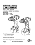
OWNERS
MANUAL
MODEL
NO.
315.173710
CAUTION:
Read Rules
for
Safe Operation
and Instructions
Carefully
I:RI:IFTgMRN
POWER
DOUBLE
PLANER
INSULATED
SAVE THIS
MANUALFOR
FUTURE REFERENCE
Warranty
Introduction
Operation
Maintenance
Repair
SEARS,
612547-404
10-00
Parts
®
Designed
exclus!vely
for and so d on y by
ROEBUCK
AND CO., Floffman
Estates,
IL 60179
P#nted In US.A,
FULL
QNE
YEAR
If this Craftsman
IT TO THE
NEAREST
If this Craftsman
the date
WARRANTY
Planer
fails
ON CRAFTSMAN
to give complete
SEARS
Planer
STORE
IN THE
is used for commercial
PLANER
satisfaction
UNITED
within one year from the date of purchase
STATES
and Sears
or rental purposes,
wi{I repair
this warranty
RETURN
it, free of charge
applies for only 90 days from
of purchase
This warranty
gives
you specific
SEARS,
legal
ROEBUCK
rights, and you may also have
AND
CO., DEFT*
other rights
817 WA, HOFFMAN
which
ESTATES,
vary from
state
to state.
IL 60179
INTRODUCTION
DOUBLE INSULATION is a concept in safety, in electric
power toots, which eliminates the need for the usual three
w_regrounded power cord and grounded supply system.
Wherever there is electric current in the tool there are two
complete sets of insulation to protect the user. All exposed
metal parts are isolated from internal metal motor components with protecting insulation.
IMPORTANT - Servicing of a toot with double insulation
requires extreme care and knowledge of the system and
should be performed only by a qualified service technician.
For service we suggest you return the tool to your neares{
Sears Store for repair. Always use original fat{dry replacement parts when servicing.
RULES FOR SAFE OPERATION
READ ALL INSTRUCTIONS
1. KNOW YOUR POWER TOOL - Read owner's
2.
3.
4.
5.
6.
7.
8.
manual carefully. Learn its applications and
limitations as well as the specific potential
hazards related to this tool.
9.
GUARD AGAINST ELECTRICAL SHOCK
BY PREVENTING BODY CONTACT WITH
GROUNDED
SURFACES,
For example:
Pipes, radiators, ranges, refrigerator enclo10.
sures.
KEEP GUARDS IN PLACE and in working
order.
KEEP WORK AREA CLEAN. Cluttered areas and benches invite accidents.
AVOID DANGEROUS ENVIRONMENT. Don't
use power tool in damp or wet locations or
11.
expose to rain. Keep work area well lit.
KEEP CHILDREN AND VISITORS AWAY.
All visitors should wear safety glasses and be
12.
kept a safe distance from work area. Do not
let visitors contact tool or extension cord.
STORE IDLE TOOLS. When not in use tools
13.
should be stored in a dry, high or locked-up
place - out of the reach of children.
Page2
DON'T FORCE TOOL It will do the job better
and safer at the rate for which it was designed.
USE RIGHT TOOL. Don't force small too[ or
attachment to do the job of a heavy duty tool.
Don't use tool for purpose not intended - for
example - Don't use a circular saw for cutting
tree limbs or logs.
WEAR PROPER APPAREL. No loose clothing or jewelry to get caught in moving parts.
Rubber gloves and non-skid footwear are recommended when working outdoors. Also,
wear protective hair covering to contain long
hair and keep it from being drawn into air
vents.
ALWAYS WEAR SAFETY GLASSES. Everyday eyeglasses have only impact-resistant lenses; they are NOT safety glasses.
PROTECT YOUR LUNGS, Wear a face or
dust mask if cutting operation is dusty.
PROTECT YOUR HEARING. Wear hearing
protection during extended periods of operation,
RULES
FORSAFEOPERATION
(Continued)
14. DON'T ABUSE CORD, Never carry tool by
cord or yank it to disconnect from receptacle.
Keep cord from heat, oil and sharp edges
15. SECURE WORK. Use clamps or a vise to
hold work. Both hands are needed to operate
the tool.
16, DON'T OVERREACH.
Keep proper footing
and balance at all times. Do not use on a
ladder or unstable support.
17. MAINTAIN TOOLS WITH CARE. Keep tools
sharp at all times, and clean for best and
safest performance. Follow instructions for
lubricating and changing accessories.
18. DISCONNECT TOOLS, When not in use, before servicing, or when changing attachments,
blades, bits, cutters, etc., all tools should be
disconnected from power supply.
19. REMOVE
ADJUSTING
KEYS
AND
WRENCHES. Form habit of checking to see
that keys and adjusting wrenches are removed
from tool before turning it on.
20. AVOID ACCIDENTAL
STARTING.
Don't
carry plugged-in tools with finger on switch.
Be sure switch is off when plugging in.
21. MAKE SURE YOUR EXTENSION CORD IS
IN GOOD CONDITION. When using an extension cord, be sure to use one heavy enough
to carry the current your product will draw. An
undersized cord will cause a drop in line voltage resulting in loss of power and overheating. A wire gage size (A`W.G) of at least 16 is
recommended for an extension cord 100 feet
or less in length. A cord exceeding 100 feet is
not recommended. If in doubt, use the next
heavier gage. The smaller the gage number,
the heavier the cord.
22. OUTDOOR
USE EXTENSION
CORDS.
When tool is used outdoors, use only extension cords suitable for use outdoors. Outdoor
approved cords are marked with the suffix WA, for example - SJTW-A or SJOW-A,
23. KEEP BLADES CLEAN. Periodically check
blades and chip exhaust for chip build-up.
Clean blades minimize stalling and kickback,
24. KEEP HANDS AWAY FROM PLANING
AREA, Keep hands away from blades. Do
not reach underneath work while blades are
rotating. DO not attempt to remove material
while blades are rotating. BLADES CONTINUE TO ROTATE AFTER RELEASING
OF SWITCH TRIGGER.
Page
25, NEVER USE IN AN EXPLOSIVE ATMOSPHERE. Normal sparking of the motor could
Jgnite fumes.
26. INSPECT TOOL CORDS PERIODICALLY
and if damaged, have repaired at your nearest Sears Repair Center. Stay conslantLy
aware of cord location.
27. INSPECT EXTENSION CORDS PERIODICALLY and replace if damaged.
28. KEEP HANDLES DRY, CLEAN, AND FREE
FROM OIL AND GREASE. Always use a
clean cloth when cleaning. Never use brake
fluids, gasoline, petroleum-based products or
any strong solvents to clean your tool.
29. STAY ALERT. Watch what you are doing
and use common sense. Do not operate toot
when you are tired. Do not rush.
30. CHECK DAMAGED PARTS. Before further
use of the tool, a guard or other part that is
damaged should be carefully checked to determine that it will operate properly and per_
form its intended function. Check for alignment of moving parts, binding of moving parts,
breakage of parts, mounting, and any other
conditions that may affect its operation. A
guard or other part that is damaged should
be properly repaired or replaced by an authorized service center unless indicated elsewhere in this instruction manual.
31. DO NOT USE TOOL IF SWITCH DOES NOT
TURN IT ON AND OFF. Have defective
switches replaced by an authorized service
center.
32. Inspect for and remove all nails from lumber
before planing.
33. DRUGS, ALCOHOL, MEDICATION. Do not
operate tool while under the influence of drugs,
alcohol, or any medication.
34. WHEN SERVICING USE ONLY IDENTICAL
CRAFTSMAN REPLACEMENT PARTS.
35. POLARIZED PLUGS. To reduce the risk of
electdc shock, this tool has a polarized plug
(one blade is wider than the other). This plug
will fit in a polarized outlet only one way. If the
plug does not fit fully in the outlet, reverse the
plug. If it still does not fit, contact a qualified
electrician to install the proper outlet. Do not
change the plug in any way,
36. SAVE THESE INSTRUCTIONS. Review them
frequently and use them to instruct others
who may use this tool If you loan someone
this tool, loan them these instructions also.
3
I
I
The operation
which
safety
of any power
tool can result
in foreign
objects
being
thrown
into your
eyes,
can result in severe eye damage, Before beginning
power tool operation,
always wear
goggles or safety glasses with side shields and e turf face shield when needed. We
recommend
Wide
with side shields,
Vision Safety Mask for use over
available
at Sears Retail Stores.
Page
4
eyeglasses
or standard
safety
glasses
I
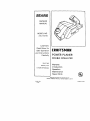
OPERATION
Your Craftsman Power Planer has been designed to
do the many planing operations which cannot be performed conveniently
or efficiently
with a larger
power planer. It is compact, lightweight, and equipped with a depth adjusting knob located at the front
of your unit. This knob also serves as a front handle
When used properly, your planer should take the
guesswork
out of planing, sizing, or beveling of
doors, windows, shutters, drawer slides and other
work. However, as with any powerful, high speed
tool, your Power Planer requires accurate set-ups
and handling.
Practice cutting
on scrap lumber
before attempting to plane finished lumber.
REAR
SWITCH
HANDLE
FRONT
HANDLE
AND bEP_H
ALLEN
WRENCH
ADJUSTING
KNOB
ALLEN
WRENCH
HOLDER
CHIP
EXHAUST
Make
sure
power
supply
is 120 volts,
Fig
60 Hz, AC only.
1
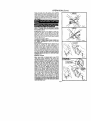
KNOW YOUR PLANER
See Figure 1
Before attempting
to use your planer familiarize
yourself with all operatir
features and safet
quirements.
ALWAYS OPERATE YOUR PLANER WITH THE CHiP
EXHAUST TURNED AWAY FROM YOUR FACE AND
EYES. ALL VISITORS SHOULD WEAR SAFETY
GLASSES AND BE KEPT A SAFE DISTANCE FROM
WORK AREA.
SWITCH
HOLD YOUR PLANER SO THAT THE BLADES DO
NOT CONTACT WORKPIECE BEFORE DEPRESSING THE SWITCH. Start your planer by depressing
the switch trigger in the handle, To turn your planer
OFF, release the switch trigger.
PLANING TOO FAST INCREASES CHIP BUILD-UP
IN TH E CHIP EXHAUST. CHIP BUILD-UP RESTRICTS
AIRFLOW AND CAN CAUSE MOTOR OVERHEAT.
iNG.
Fig, 2
PREPARING FOR OPERATION
For ease of operation your planer has both a front
handle and a rear handle. See Figure 1. NOTE: The
front handle also serves as the depth adjusting knob.
This provides for two-hand
operation, which is
necessary in order to maintain proper control of
your planer and keep both hands clear of the bfades
and cutting area. When operating your planer always
use both hands holding the depth adjusting knob
with your left hand and the rear handle with your
right hand as shown in Fig. 2. In this position, your
planer is easier to handle and you are clear of the
chip exhaust.
Page 5
OPERATION
(Cont.)
Keep cord away fro11 the cutting area. ALWAYS
place the cord to prevent it from hanging on the work
while making a cut. If the cord hangs up on the work
during a cut, release the switch trigger immediately.
Unplug your planer and check cord for damage, If no
damage, reposition the cord to prevent it from hanging up again,
WRONG
Fig. 3
KNOW THE RIGHT WAY TO USE YOUR PLANER.
SEE F/G. 2. NEVER USE YOUR PLANER AS SHOWN
IN FIGURES 3 AND 4.
WRONG
ALWAYS keep control of your planer. It makes cutting easier and safer. TO help keep control, always
support your work so the cut will be on your right
Clamp your work so it will not move during the cut
See Figure 5. The work moving during a cut could
resuff in the loss of control of your planer possibly
causing serious injury.
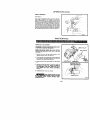
TO ADJUST PLANING DEPTH
DISCONNECT YOUR PLANER FROM POWER SUPPLY WHILE ASSEMBLING
PARTS OR MAKING
ADJUSTMENTS.
_Fig
4
CORRECT
Plantng depth is adjustable from o to .020 inch and is
adjusted
by rotating
the depth adjusting
knob
located on the front of your planer. See Figure 6. To
increase cutting depth, rotate knob clockwise. To
de_rease cutting depth, rotate knob counterclockwise. It _s recommended
that test cuts be made in
scrap wood after each adjustment to make sure that
the desired amount of wood is being removed by
your planer, NOTE: TO PROTECT BLADES DURING
STORAGE, TRANSPORTING, ETC., SET DEPTH ADJUSTINO TO O.
GENERAL CUTTING
Adjust your planer to desired depth of cut. WITH
YOUR LEFT HAND HOLDING THE DEPTH ADJUSTING KNOB AND YOUR RIGHT HAND HOLDING
THE REAR HANDLE, place front shoe on workpiece.
Make sure blades are not touching the work. Apply
pressure to the depth adjusting knob so that the
front shoe is flat on the work. Pull switch trigger to
start your planer and let the motor reach maximum
speed. Hold your planer firmly and push forward
steadily into your work. NOTE; Push planer forward
slowly if a smooth cut is desired. As the end of the
planed cut is reached, apply downward pressure
toward the rear handle. This will help keep the rear
section of the base in contact with the work preventing the front of your planer from dipping or gouging
your cut. Be careful to avoid hitting nails during planing operation. This could nick, crack or damage
blades. We suggest that you keep an extra set of
blades on hand. AS soon as the blades in your p_aner
show signs of becoming dull, replace them. NOTE:
THE BLADES IN YOUR PLANER ARE REVERSIBLE.
THEREFORE THEY CAN BE ROTATED UNTIL BOTH
SfDES BECOME DULL.
Fig. 5
TO INCREASE
'CUTTING DEPTH
TO DECREASE
CUTTING DEPTH
DEP
Fig;,6
Page 6
OPERATION
(Cont.)
EDGE CHAMFERING
See Figure 7.
Your planer is designed with a groove in the front
shoe. The purpose of this groove is chamfering
edges. Before making a cut on good lumber, make a
few cuts on scrap lumber to determine the amount to
be removed from the board. Holding the depth adjusting knob with your left hand and the rear handle
with your right hand, place the groove on the surface
to be cut and move the tool slowly into the work.
Maintain downward pressure to keep your planer flat
at the beginning and the end of the work surface.
Fig, 7
MAINTENANCE
TIMING
BELT REPLACEMENT
DISCONNECT YOUR PLANER FROM POWER SUPPLY BEFORE CHANGING TIMING BELT.
SMALL PULLEY
WHEN REPLACING TIMING BELT, USE RECOMMENDED REPLACEMENT BELT ONLY. See Parts
List', Page 11.
1. Remove
remove
the two (2)
the belt cover.
belt
See
cover
Figure
screws.
8.
BELT COVER
Then
2. Force old belt from small pugey with a screwdriver
and remove it from large pulley, If it is worn out,
simply cut the old belt and remove it.
LARGE PULLEY
3. Install new belt over large pulley first. See Figure
9.
TIMING
BELT
COVER
SCREWS
Fig, 8
POSITION HERE AND
TURN LARGE PULLEY
4. Holding the belt as shownln figu_ 9, p_ssthe
belt onto the smag pulley. NOTE: TO SIMPLIFY
THE PROCESS, TURN THE LARGE PULLEY AS
YOU PRESS THE BELT ONTO THE SMALL
PULLEY.
5. Reassemble belt cover and screws.
BELT COVER IS PART OF THE
DOUBLE INSULATED SYSTEM. NEVER ATTEMPT
TO OPERATE YOUR PLANER WITHOUT
BELT
COVERIN PLACE.
LARGE PULLEY
Fig. 9
Page
7
MAINTENANCE
RLADE
THE
BLADES
'THEREFORE,
ONE EDGE
ALWAYS
PAIRS,
DO NOT
(Cont.)
REPLACEMENT
IN YOUR
THEY
BECOMES
REPLACE
ATTEMPT
NEVER
ATTEMPT
WITH ONLY ONE
PLANER
ARE
CAN
BE
DULL,
OR
REVERSIBLE,
REVERSED
REVERSE
TO SHARPEN
BLADE
I_J
PIECE OF
WHEN
BLADES
CLAMP
1/8 IN, ALLEN
/ WRENCH
IN
BLADES.
TO OPERATE
YOUR
BLADE
INSTALLED.
\
PLANER
CUTTER
BLADE
Fig
1
Place your
workbench
2
Remove
provided
planer
in an upside
See Figure
10
from storage area,
with your planer
down
position
10
on
_P'_-
_-_--i
_--_-SCR
EWS
the 1/8 inch allen wrench
See Figure
1, page 4.
NOTE:
TO prevent
rotation
changing
the blades,
place
between
the arbor at)d the
of the arbor
whi_e
a amal_ piece of wood
base¸ See Figure
10
3, Using the allen wrench, remove the three (3)
screws securing blade. See Figure 11,
4. Remove blade clamp and cutter blade.
5 Clean any sawdust or wood particles from cutter
arbor and from aH parts you have removed
6. Place new cutter blade over plastic Iocators See
Figure 12. NOTE: Place front of cutter blade slots
so that they touch plastic Iocators. Do not move
or adjust plastic Iocators. They have been factory
adjusted to assure proper depth setting (s maintained and that blades remain parallel
7. Replace blade e_amp and screws
8. Securely tighten all screws with alie# wrench,
9. Remove the piece of wood from your planer.
10. Repeat the above procedure to change the other
blade.
11 Return allen wrench to storage area,
I
liP
LP& ST' s
Fig.
11
CUTTER BLADE
SCREW
PLASTIc_CUTTER
LOCATOR
Page 8
BLADE CLAMP
GENERAL
O'gy the parts shown
on parts list, page eleven,
are
intended
to be repaired
or replaced
by the customer
All other
parts
represent
an important
part of [he
double
insulation
system and Should be serviced
only by a qualified
service
technician
Avoid
using
solvents
when
cleanlng
plastic
parts
Most plastics
are susceptible
to various
types
of
commercial
Solvents
and may be damaged
by their
usa Use clean
cJoths
to remove
dirt,
carbon
dusl
etc.
When electric
tools
are used on fiberglass
bo_ts
sports cars, elc.. it has been found that they are sub
ject to accelerated
wear
and possible
prenl_t_re
failure,
as the fiberglass
chips
and grindings
are
highly
abrasive
to bearings,
brushes,
commutator
etc Consequently
it is not recommended
1hat this
too_ be used for extended
work on any fibergtass
material
During
any use on fibe(glass
it is exlremely
importanl
that the tool i5 cleaned
frequentJy by blow
mg
with
an air
jet
ALWAYS
WEAR
SAFETY
GLASSES,
DUST MASK,
OR EYE SHIELDS
BEFORE
BEGINNING
POWER
TOOL OPI_RAT]ON
OR BLOWING DUST.
LUBRICATION
AI! the bearings
in this tool are lubricated
with a suf
fieient
amount
of high grade lubricant
for the life of
the
unit
under
normal
operating
condffions,
Ulerefore
no further
lubrication
is required.
EXTENSION
COROS
Extension
Cord Length
25 50 Ft
50-100 FT
The use o{ any extension
cord wid cause
some loss
of power¸
To keep the loss to a minimum
and to provent tool overhealing,
follow
the r_eommended
cord
sizes on the chart
at right
When
tool is used out.
doors,
use only extension
cords
suitable
for ouldoor
use and so marked
Extension
cords
are available
at
Sears
Retail
Wire
Stores
_THE
FOLLOWING
RECOMMENDED
ACCESSORIES
WERE AVAILABLE
AT THE TIME THIS MANUAL
I'RRFTSMRN.
The
use
Edge Guide ( 9
of attachments
1732g)
or accessories
REMEMBER:
Replace blades when they become dull.
Glean blades often.
Periodically remove chip build-up behind t he blades.
Periodically clean chip bugd-up in the chip exhaust.
NOTE: It may be necessa_ to remove blades in order to
clean them or to clean chip build up behind the blades See
BLADE REPLACEMENT for proper instructions on how Io
remove and instarr blades for cleaning
Page g
ARE CURRENT
WAS PRINTED,
Blades
not listed
above
AND
'
9 1;'324
might
be hazardous.
Size A.W.G.
18
16
CRAFTSMAN
POWER PLANER
-- MODEL NUMBER
315.173710
)
8\
Page 10
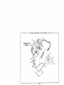
CRAFTSMAN
I
POWER PLANER -- MODEL NUMBER 315.173710
planer. Always mention the Model Number in all correspondence regarding
The Model
your
POWERNumber
PLANER
will orbewhen
foundordering
on a plate
repair
attached
parts, to the bottom of your J
SEE BACK PAGE FOR PARTS ORDERING
Key
NO.
1
2
3
4
5
6
7
8
9
10
11
12
13
NOTE:
PARTS
Parl
Number
LIST
Description
820193-005
998933-001
998934-002
998891-001
617986-009
973580001
998942-002
998938-002
998953-001
998932-001
998991-001
998588-002
998989-001
612547-404
"A" - The assembty
• Allen Wrench
Sprocket
Ouan.
(1/8 In, Item No, 9-28135)
.............................
1
.....................................................
1
Timing
Belt ...................................................
Belt Cover ....................................................
• Screw
{#8-10
1
1
x 5/8 In. Pan Hd. "EF.).................................
2
Logo Plate ....................................................
Bottom
Plate ..................................................
1
1
• Screw (#6-32 x 5/8 In, Flat Hd, TC.) .................................
Data Plate ....................................................
Sprocket
• Screw
Blade
1
.....................................................
1
{#10-32 x 1/2 In. Button Hd. Cap Screw) ........................
Clamp ..................................................
6
2
Blade ........................................................
Owner's
Manual
shown
possibility
of alteration
Repair Center.
Contact
*Standard
**Available
***Available
INSTRUCTIONS
represents
an important
part of the Double
or damage to the System, service
your nearest Sears Retail Store.
Hardware ttem -- May Be Purchased
From Div. 98 -- Source 980,00
at Your Nearest
Sears Retail Store
Page
11
2
should
Locally
Insulated
be performed
System,
by your
To avoid the
nearest
Sears
Getit
fixed, at your home or ours!
For repair of major brand appliances in your own home...
no matter who made it, no matter who sold it!
1-800-4-MY-HOME
sMAnytime,
day or night
(1-800-469-4663)
www.sears.com
To bring in products such as vacuums, lawn equipment and electronics
for repair, call for the location of your nearest Sears Parts & Repair Center.
1-800-488-1222
Anytime,
day or night
www.sears.com
For the replacement parts, accessories and owner's manuals
that you need to do-it-yourself, call Sears PartsDireetSM]
1-800-366-PART
(1-800-366-7278)
earn 11p.m,
CST,
7 days a week
www.sears.com/partsdirect
To purchase or inquire about a Sears Service Agreement:
1-800-827-6655
7 a.m. - 5 p.m. CST, Men.
Para pedir servicio de reparaci6n a domicilio,
y para ordenar piezas con entrega a domicilio:
1 *888-SU-HOGAR
s_
Sat.
Au Canada
(1-877-533-6937)
(1-888-784-6427)
[
1
HomeCentra:
® R_gi_tered Tfa_emar_ / _= Tr_em,_rk
pour service en frangais:
1-877-LE-FOYER s.
or se_,_
J
m_4_:_;o