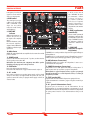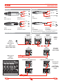
1
english
italiano
USER’S MANUAL y MANUALE D’USO
w w w. p ro e l g ro u p. co m
SAFETY AND PRECAUTIONS
AVVERTENZE PER LA SICUREZZA
This marking shown on the product or its literature, indicates that it should not
be disposed with other household wastes at the end of its working life. To prevent
possible harm to the enviroment or human health from uncontrolled waste disposal,
please separate this from other types of wastes and recycle it responsibly to promote
the sustainable reuse of material resources. Household users should contact either the
retailer where they purchased this product, or their local government office, for details
of where and how they can take this item for environmentally safe recycling. Business users should
contact their supplier and check the terms and conditions of the purchase contract. This product
should not be mixed with other commercial wastes for disposal.
Il marchio riportato sul prodotto o sulla documentazione indica che il prodotto non
deve essere smaltito con altri rifiuti domestici al termine del ciclo di vita. Per evitare
eventuali danni all’ambiente si invita l’utente a separare questo prodotto da altri tipi
di rifiuti e di riciclarlo in maniera responsabile per favorire il riutilizzo sostenibile delle
risorse materiali. Gli utenti domestici sono invitati a contattare il rivenditore presso il
quale è stato acquistato il prodotto o l’ufficio locale preposto per tutte le informazioni
relative alla raccolta differenziata e al riciclaggio per questo tipo di prodotto. Gli utenti aziendali sono
invitati a contattare il proprio fornitore e verificare i termini e le condizioni del contratto di acquisto.
Questo prodotto non deve essere smaltito unitamente ad altri rifiuti commerciali.
The lightning flash with arrowhead symbol within an equilateral triangle is intended
to alert the user to the presence of uninsulated “dangerous voltage” within the
product’s enclosure, that may be of sufficient magnitude to constitute a risk of
electric shock to persons.
Il simbolo del lampo con freccia in un triangolo equilatero intende avvertire
l'utilizzatore per la presenza di "tensioni pericolose" non isolate all'interno
dell'involucro del prodotto, che possono avere una intensità sufficiente a costituire
rischio di scossa elettrica alle persone.
The exclamation point within an equilateral triangle is intended to alert the user to
the presence of important operating and maintenance (servicing) instructions in the
literature accompanying the appliance.
Il punto esclamativo in un triangolo equilatero intende avvertire l'utilizzatore
per la presenza di importanti istruzioni per l'utilizzo e la manutenzione nella
documentazione che accompagna il prodotto.
SAFETY AND PRECAUTIONS
AVVERTENZE PER LA SICUREZZA
• ATTENZIONE - Durante le fasi di uso o manutenzione, devono essere prese alcune precauzioni
onde evitare danneggiamenti alle strutture meccaniche ed elettroniche del prodotto.
Prima di utilizzare il prodotto, si prega di leggere attentamente le seguenti istruzioni per la
sicurezza. Prendere visione del manuale d’uso e conservarlo per successive consultazioni:
– In presenza di bambini, controllare che il prodotto non rappresenti un pericolo.
– Posizionare l’apparecchio al riparo dagli agenti atmosferici e a distanza di sicurezza dall’acqua,
dalla pioggia e dai luoghi ad alto grado di umidità.
– Collocare o posizionare il prodotto lontano da fonti di calore quali radiatori, griglie di riscaldamento
e ogni altro dispositivo che produca calore.
– Collocare o posizionare il prodotto in modo che non ci siano ostruzioni alla sua propria ventilazione
e dissipazione di calore. Non installare in uno spazio limitato.
– Evitare che qualsiasi oggetto o sostanza liquida entri all’interno del prodotto.
– Il prodotto deve essere connesso esclusivamente alla rete elettrica delle caratteristiche descritte nel
manuale d’uso o scritte sul prodotto, usando esclusivamente il cavo rete in dotazione e controllando
sempre che sia in buono stato, in particolare la spina e il punto in cui il cavo esce dal prodotto.
– Non annullare la sicurezza garantita dall'uso di spine polarizzate o con messa a terra.
– Fare attenzione che il punto di alimentazione della rete elettrica sia dotato di una efficiente presa
di terra.
– Disconnettere il prodotto dalla rete elettrica durante forti temporali o se non viene usato per un
lungo periodo di tempo.
– Non disporre oggetti sul cavo di alimentazione, non disporre i cavi di alimentazione e segnale in
modo che qualcuno possa incianparci. Altresì non disporre l’apparecchio sui cavi di altri apparati.
Installazioni inappropriate di questo tipo possono creare la possibilità di rischio di incendio e/o
danni alle persone.
– Questo prodotto può essere capace di produrre livelli sonori che possono causare perdite d’udito
permanenti. Si raccomanda di evitare l’esposizione ad alti livelli sonori o livelli non confortevoli per
lunghi periodi di tempo. Se si notano perdite d’udito o acufeni (fischii) consultare un audiologo. La
sensibilità alla perdita di udito causata da eccessiva esposizione al rumore varia considerevolmente
da individuo a individuo, ma mediamente ciascuno può accusare perdita di udito se esposto al rumore
per un certo periodo di tempo. Come suggerimento viene riportata la tabella dei tempi massimi di
esposizione giornaliera al rumore al fine di evitare perdite di udito, fonte della tabella è l'ente per
la salute degli Stati Uniti (OSHA):
• CAUTION - Before using this product read carefully the following safety instructions. Take a look
of this manual entirely and preserve it for future reference.
When using any electric product, basic precautions should always be taken, including the
following:
– To reduce the risk, close supervision is necessary when the product is used near children.
– Protect the apparatus from atmospheric agents and keep it away from water, rain and high
humidity places.
– This product should be site away from heat sources such as radiators, lamps and any other device
that generate heat.
– This product should be located so that its location or position does not interfere with its proper
ventilation and heating dissipation. Do not install in a confined space.
– Care should be taken so that objects and liquids do not go inside the product.
– The product should be connected to a power supply mains line only of the type described on the
operating instructions or as marked on the product. Connect the apparatus to a power supply using
only power cord included making always sure it is in good conditions, specially the plug and the point
where it exit from the apparatus.
– Do not cancel the safety feature assured by means of a polarized line plug (one blade wider than
the other) or with a earth connection.
– Make sure that power supply mains line has a proper earth connection.
– Power supply cord should be unplugged from the outlet during strong thunderstorm or when left
unused for a long period of time.
– Do not place objects on the product’s power cord or place it in a position where anyone could
trip over, walk on or roll anything over it. Do not allow the product to rest on or to be installed over
power cords of any type. Improper installations of this type create the possibility of fire hazard and/or
personal injury.
– This product may be capable of producing sound levels that could cause permanent hearing
loss. Exposure to extremely high noise levels may cause permanent hearing loss. Individuals
vary considerably in susceptibility to noise-induced hearing loss, but nearly everyone will lose
some hearing if exposed to sufficiently intense noise for a period of time. The U.S. Government’s
Occupational Safety and Health Administration (OSHA) has specified the permissible noise level
exposures shown in the following chart. According to OSHA, any exposure in excess of these
permissible limits could result in some hearing loss. To ensure against potentially dangerous exposure
to high sound pressure levels, it is recommended that all persons exposed to equipment capable of
producing high sound pressure levels use hearing protectors while the equipment is in operation. Ear
plugs or protectors in the ear canals or over the ears must be worn when operating the equipment
in order to prevent permanent hearing loss if exposure is in excess of the limits set forth here.
Duration Per Day
In Hours
Sound Level dBA
Slow Response
Typical
Example
8
90
Duo in small club
6
92
4
95
3
97
2
100
1.5
102
1
105
0.5
110
0.25 or less
115
Subway Train
Very loud classical music
Traffic noise
Ore di esposizione
giornaliera
Livello sonoro in dBA
costante di tempo SLOW
Esempio
Tipico
8
90
Duo acustico in un piccolo club
6
92
4
95
3
97
2
100
1.5
102
1
105
0.5
110
0.25 or less
115
Treno metropolitano
Musica classica molto forte
Rumore da traffico urbano intenso
Parte più rumorosa di un concerto rock
Si fà presente inoltre che sia i bambini che gli animali domestici sono più sensibili al rumore
intenso.
Loudest parts at a rock concert
Keep your's attention that childrens and pets are more suscetible to excessive noise levels.
ENG
2
ITA
SAFETY AND PRECAUTIONS
AVVERTENZE PER LA SICUREZZA
IN CASE OF FAULT
IN CASO DI GUASTO
• In case of fault or maintenance this product should be inspected only by qualified service
personnel when:
– There is a flaw either in the connections or in the supplied connecting cables.
– Liquids have spilled inside the product.
– The product has fallen and been damaged.
– The product does not appear to operate normally or exhibits a marked change in performance.
– The product has been losted liquids or gases or the enclosure is damaged.
• Do not operate on the product, it has no user-serviceable parts inside.
• Refer servicing to an authorized maintenance centre.
• In caso di guasto o manutenzione questo prodotto deve essere ispezionato da personale
qualificato quando:
– Ci sono difetti sulle connessioni o sui cavi di collegamento in dotazione.
– Sostanze liquide sono penetrate all’interno del prodotto.
– Il prodotto è caduto e si è danneggiato.
– Il prodotto non funziona normalmente esibendo una marcato cambio di prestazioni.
– Il prodotto perde sostanze liquide o gassose o ha l’involucro danneggiato.
• Non intervenire sul prodotto.
• Rivolgersi a un centro di assistenza autorizzato Proel.
CE CONFORMITY
CONFORMITÀ CE
• Proel products comply with directive 89/336/EEC (EMC) and following modifications 92/31/EEC
and 93/68/EEC, as stated in EN 55103-1 and EN 55103-2 standards and with directive 73/23/EEC
(LVD) and following modifications 93/68/EEC, as stated in EN 60065 standard.
• I Prodotti Proel sono conformi alla direttiva 89/336/EEC (EMC) e successive modifiche 92/31/EEC
e 93/68/EEC, secondo gli standard EN 55103-1 ed EN 55103-2 ed alla direttiva 73/23/EEC (LVD) e
successive modifiche 93/68/EEC, secondo lo standard EN 60065.
PACKAGING, SHIPPING AND COMPLAINT
IMBALLAGGIO, TRASPORTO E RECLAMI
• This unit package has been submitted to ISTA 1A integrity tests. We suggest you control the unit
conditions immediately after unpacking it.
• If any damage is found, immediately advise the dealer. Keep all unit packaging parts to allow
inspection.
• Proel is not responsible for any damage that occurs during shipment.
• Products are sold “delivered ex warehouse” and shipment is at charge and risk of the buyer.
• Possible damages to unit should be immediately notified to forwarder. Each complaint for
manumitted package should be done within eight days from product receipt.
• L’imballo è stato sottoposto a test di integrità secondo la procedura ISTA 1A. Si raccomanda di
controllare il prodotto subito dopo l’apertura dell’imballo.
• Se vengono riscontrati danni informare immediatamente il rivenditore. Conservare quindi
l’imballo completo per permetterne l’ispezione.
• Proel declina ogni responsabilità per danni causati dal trasporto.
• Le merci sono vendute “franco nostra sede” e viaggiano sempre a rischio e pericolo del
distributore.
• Eventuali avarie e danni dovranno essere contestati al vettore. Ogni reclamo per imballi
manomessi dovrà essere inoltrato entro 8 giorni dal ricevimento della merce.
WARRANTY AND PRODUCTS RETURN
GARANZIE E RESI
• Proel products have operating warranty and comply their specifications, as stated by
manufacturer.
• Proel warrants all materials, workmanship and proper operation of this product for a period of two
years from the original date of purchase. If any defects are found in the materials or workmanship
or if the product fails to function properly during the applicable warranty period, the owner should
inform about these defects the dealer or the distributor, providing receipt or invoice of date of
purchase and defect detailed description. This warranty does not extend to damage resulting from
improper installation, misuse, neglect or abuse. Proel S.p.A. will verify damage on returned units,
and when the unit has been properly used and warranty is still valid, then the unit will be replaced
or repaired. Proel S.p.A. is not responsible for any "direct damage" or "indirect damage" caused by
product defectiveness.
• I Prodotti Proel sono provvisti della garanzia di funzionamento e di conformità alle proprie
specifiche, come dichiarate dal costruttore.
• La garanzia di funzionamento è di 24 mesi dopo la data di acquisto. I difetti rilevati entro il
periodo di garanzia sui prodotti venduti, attribuibili a materiali difettosi o difetti di costruzione,
devono essere tempestivamente segnalati al proprio rivenditore o distributore, allegando evidenza
scritta della data di acquisto e descrizione del tipo di difetto riscontrato. Sono esclusi dalla garanzia
difetti causati da uso improprio o manomissione. Proel SpA constata tramite verifica sui resi la
difettosità dichiarata, correlata all’appropriato utilizzo, e l’effettiva validità della garanzia; provvede
quindi alla sostituzione o riparazione dei prodotti, declinando tuttavia ogni obbligo di risarcimento
per danni diretti o indiretti eventualmente derivanti dalla difettosità.
INSTALLATION AND DISCLAIMER
INSTALLAZIONE E LIMITAZIONI D’USO
• Proel products have been expressly designed for audio application, with signals in audio
range (20Hz to 20kHz). Proel has no liability for damages caused in case of lack of maintenance,
modifications, improper use or improper installation non-applying safety instructions.
• The installation of these speakers is provided for indoors, in case of use outdoors be sure that the
speakers are installed correctly in a safe location protected from wind, rain and umidity. To avoid
performance deterioration of mechanical, acoustics and electrical parts is not advisable to leave these
speakers exposed outdoors for a long period of time, so we suggest a temporary installation for the
limited sound events.
• The installation of these speakers is provided for floor or by means of specific stands able to
support their weight. Therefore avoid installation on unstable elements such as: furnitures, chairs
and vibrant surfaces as stages or other speakers without appropriate fix point specifically designed
to avoid speaker movement. Then avoid the use of inadequate supports, we suggest to use PROEL
stands and accessories only.
• In case of the speakers are provided of rigging points: DO NOT SUSPEND THE SPEAKERS FROM THE
HANDLES, use exclusively these rigging points. Consult professional rigger or structural engineers
prior to suspending loudspeakers from a structure not intended for that use. Always know the
working load limit of the structure supporting the loudspeakers. Always make sure that the rigging
hardware minimum rating is at least five times the actual load, speakers and rigging hardware.
• In case of suspended installations of active loudspeakers where is not possible to turn on and off
the speakers from their appropriate switches, we recomend to install switches on the mains lines,
for this purpose consult an expert electrician for the exact dimensioning of wiring.
• Locate the speakers as far away as possible from radio or television receivers or other sensitive
equipment. These speakers have a strong magnetic field which can induce hum and noise into
unshielded devices that are located nearby with consequent deterioration of reception of image and
sound.
• Proel S.p.A. reserves the right to change these specifications at any time without notice.
• Proel S.p.A. declines any liability for damages to objects or persons caused by lacks of
maintenance, improper use, installation not performed with safety precautions and at the state of
the art.
ENG
• I Prodotti Proel sono destinati esclusivamente ad un utilizzo specifico di tipo sonoro: segnali di
ingresso di tipo audio (20Hz-20kHz). Proel declina ogni responsabilità per danni a terzi causati da
mancata manutenzione, manomissioni, uso improprio o installazione non eseguita secondo le norme
di sicurezza.
• L'installazione di questi altoparlanti è prevista per uso interno, in caso di utilizzo all'esterno
assicurarsi che gli altoparlanti siano installati correttamente in un luogo sicuro e protetto dal vento,
pioggia e umidità. Al fine di non deteriorarne le prestazioni meccaniche, acustiche ed elettriche non
è consigliato lasciare questi altoparlanti esposti all'aperto per lunghi periodi di tempo, si consiglia
pertanto una installazione temporanea all'evento da sonorizzare.
• L'installazione di questi altoparlanti è prevista a pavimento o tramite specifici supporti adeguati
al peso da sostenere. Pertanto evitare l'installazione su elementi instabili quali: mobili, sedie e
superfici vibranti quali palchi e altri altoparlanti non dotati di fissaggi atti a evitare spostamenti
dell'altoparlante. Quindi evitare di utilizzare supporti non adeguati, si consiglia di usare solo i
supporti suggeriti da PROEL.
• Qualora gli altoparlanti siano muniti di punti di fissaggio per la sospensione: NON SOSPENDERE GLI
ALTOPARLANTI DALLE MANIGLIE usare esclusivamente questi punti di fissaggio. Consultare attrezzisti
professionisti o ingegneri strutturali prima di sospendere altoparlanti da strutture non intese per
questo specifico scopo. Non superare il limite di carico della struttura che sosterrà gli altoparlanti.
Assicurarsi che tutte le meccaniche di sostegno siano in grado di sopportare un peso almeno 5 volte
superiore al carico degli altoparlanti incluse le meccaniche di sospensione.
• Nel caso di installazioni sospese di altoparlanti attivi in cui non sia possibile l'uso dei singoli
interruttori degli altoparlanti per l'accensione e lo spegnimento dei medesimi, si raccomanda
l'installazione di interruttori sulle linee di alimentazione della rete elettrica, a tale proposito
consultare un esperto elettricista per il corretto dimensionamento dell'impianto elettrico.
• Installare questi altoparlanti il più lontano possibile da radioricevitori e televisori. Un altoparlante
installato in prossimità di questi apparati può causare interferenza e rumore con conseguente
degrado della ricezione di immagini e suoni.
• La Proel S.p.a. si riserva di modificare il prodotto e le sue specifiche senza preavviso.
• Proel declina ogni responsabilità per danni a terzi causati da mancata manutenzione,
manomissioni, uso improprio o installazione non eseguita secondo le norme di sicurezza e a regola
d'arte.
3
ITA
SAFETY AND PRECAUTIONS
AVVERTENZE PER LA SICUREZZA
POWER SUPPLY AND MAINTENANCE
ALIMENTAZIONE E MANUTENZIONE
• Clean only with dry cloth.
• Check periodically that the slots for its proper ventilation and heating dissipation are not
obstructed by dust, remove the dust using a dry brush or a compressed air gun.
• The amplified loudspeakers of Proel have been designed with CLASS I construction and must be
connected always to a mains socket outlet with a proctetive earth connection (the third grounding
prong).
• Before connecting the product to the mains outlet make certain that the mains line voltage
matches that shown on the rear of the product, a tolerance of up to ±10% is acceptable.
• Inside the amplified loudspeakers are present special safety devices such as:
Fuse on rear panel.
Amplifier over-heating protection.
Protection against excessive power applied at each speaker.
• Inside the passive loudspeakers are present special safety devices such as:
Protection against excessive power applied at HF-driver speaker.
• THE REPLACEMENT OF FUSES INSIDE THE APPARATUS MUST BE MADE ONLY BY
QUALIFIED PERSONNEL.
• CHECK THE CONDITION OF THE PROTECTION FUSE, ACCESSIBLE OUTWARD, ONLY
WITH THE APPARATUS SWITCHED OFF AND DISCONNECTED FROM THE MAINS LINE
OUTLET.
• REPLACE THE PROTECTION FUSE ONLY WITH SAME TYPE AS SHOWN ON THE
PRODUCT.
• IF AFTER THE SUBSTITUTION, THE FUSE INTERRUPTS AGAIN THE APPARATUS
WORKING, DO NOT TRY AGAIN THEN CONTACT THE PROEL SERVICE CENTER.
• Pulire il prodotto unicamente con un panno asciutto.
• Controllare periodicamente che le aperture di raffredamento non siano ostruite da accumuli di
polvere, provvedere alla rimozione della polvere mediante un pennello o aria compressa.
• Gli altoparlanti amplificati della Proel sono costruiti in CLASSE I e prevedono sempre il
collegamento mediante presa di corrente con terminale di terra di protezione (terzo terminale di
terra).
• Prima di collegare l'apparecchio alla presa di corrente, accertatevi che la tensione di rete corrisponda
a quella indicata sul retro dell’apparato, è consentito un margine del ±10% rispetto al valore
nominale.
• Negli altoparlanti amplificati sono presenti anche i seguenti dispositivi di sicurezza:
fusibile sul pannello posteriore.
protezioni termiche dell'amplificatore.
protezioni alla potenza erogata in eccesso ai singoli altoparlanti.
• Negli altoparlanti passivi sono presenti anche i seguenti dispositivi di sicurezza:
protezione alla potenza erogata in eccesso all'altoparlante driver delle alte frequenze.
• LA SOSTITUZIONE DI FUSIBILI ALL'INTERNO DELL'APPARATO È CONSENTITO
ESCLUSIVAMENTE A PERSONALE QUALIFICATO.
• CONTROLLARE LO STATO DEI FUSIBILI DI PROTEZIONE ESCLUSIVAMENTE AD
APPARATO SPENTO E DISCONNESSO DALLA RETE ELETTRICA.
• RIMPIAZZARE IL FUSIBILE DI PROTEZIONE ESCLUSIVAMENTE CON UN FUSIBILE CON
LE MEDESIME CARATTERISTICHE RIPORTATE SUL PRODOTTO.
• SE DOPO LA SOSTITUZIONE, IL FUSIBILE INTERROMPE NUOVAMENTE IL
FUNZIONAMENTO DELL'APPARATO, NON INSISTERE E CONTATTARE IL SERVIZIO
ASSISTENZA PROEL.
FCC COMPLIANCE NOTICE
This device complies with part 15 of the FCC rules. Operation is subject to the following two conditions:
(1) This device may not cause harmful interference, and
(2) this device must accept any interference received, including interference that may cause undesired
operation.
CAUTION: Changes or modifications not expressly approved by the party responsible for compliance could
void the user’s authority to operate the equipment.
NOTE: This equipment has been tested and found to comply with the limits for a Class B digital device, pursuant to
part 15 of the FCC Rules. These limits are designed to provide reasonable protection against harmful interference
in a residential installation. This equipment generates, uses, and can radiate radio frequency energy and, if
not installed and used in accordance with the instruction manual, may cause harmful interference to radio
communications. However, there is no guarantee that interference will not occur in a particular installation. If
this equipment does cause harmful interference to radio or television reception, which can be determined by
turning the equipment off and on, the user is encouraged to try to correct the interference by one or more of
the following measures:
• Reorient or relocate the receiving antenna.
• Increase the separation between the equipment and receiver.
• Connect the equipment into an outlet on a circuit different from that to which the receiver is connected.
• Consult the dealer or an experienced radio/TV technician for help.
ENG
4
ITA
CONTENTS
INDICE
CONTENTS
INDICE
SAFETY AND PRECAUTIONS . . . . . . . . . . . . . . . . . . . . . . . . . . . . . . . . . .2
IN CASE OF FAULT . . . . . . . . . . . . . . . . . . . . . . . . . . . . . . . . . . . . . . . . . .3
CE CONFORMITY . . . . . . . . . . . . . . . . . . . . . . . . . . . . . . . . . . . . . . . . . . .3
PACKAGING, SHIPPING AND COMPLAINT . . . . . . . . . . . . . . . . . . . . . . .3
WARRANTY AND PRODUCTS RETURN . . . . . . . . . . . . . . . . . . . . . . . . . .3
INSTALLATION AND DISCLAIMER. . . . . . . . . . . . . . . . . . . . . . . . . . . . . .3
POWER SUPPLY AND MAINTENANCE . . . . . . . . . . . . . . . . . . . . . . . . . .4
INTRODUCTION . . . . . . . . . . . . . . . . . . . . . . . . . . . . . . . . . . . . . . . . . . . .6
REAR PANEL . . . . . . . . . . . . . . . . . . . . . . . . . . . . . . . . . . . . . . . . . . . . . .7
CONNECTIONS. . . . . . . . . . . . . . . . . . . . . . . . . . . . . . . . . . . . . . . . . . . . .9
CONNECTION EXAMPLES . . . . . . . . . . . . . . . . . . . . . . . . . . . . . . . . . . . .9
TROUBLESHOOTING . . . . . . . . . . . . . . . . . . . . . . . . . . . . . . . . . . . . . . 10
TECHNICAL SPECIFICATIONS . . . . . . . . . . . . . . . . . . . . . . . . . . . . . . . 11
POLAR DIAGRAMS AND FREQUENCY RESPONSE . . . . . . . . . . . . . . . 12
DIMENSIONS AND FLYING POINTS. . . . . . . . . . . . . . . . . . . . . . . . . . . 13
ACCESSORIES . . . . . . . . . . . . . . . . . . . . . . . . . . . . . . . . . . . . . . . . . . . 14
AVVERTENZE PER LA SICUREZZA . . . . . . . . . . . . . . . . . . . . . . . . . . . . . .2
IN CASO DI GUASTO . . . . . . . . . . . . . . . . . . . . . . . . . . . . . . . . . . . . . . . .3
CONFORMITÀ CE . . . . . . . . . . . . . . . . . . . . . . . . . . . . . . . . . . . . . . . . . . .3
IMBALLAGGIO, TRASPORTO E RECLAMI . . . . . . . . . . . . . . . . . . . . . . . .3
GARANZIE E RESI . . . . . . . . . . . . . . . . . . . . . . . . . . . . . . . . . . . . . . . . . .3
INSTALLAZIONE E LIMITAZIONI D’USO . . . . . . . . . . . . . . . . . . . . . . . . .3
ALIMENTAZIONE E MANUTENZIONE . . . . . . . . . . . . . . . . . . . . . . . . . . .4
INTRODUZIONE . . . . . . . . . . . . . . . . . . . . . . . . . . . . . . . . . . . . . . . . . . . .6
PANNELLO POSTERIORE . . . . . . . . . . . . . . . . . . . . . . . . . . . . . . . . . . . . .7
CONNESSIONI . . . . . . . . . . . . . . . . . . . . . . . . . . . . . . . . . . . . . . . . . . . . .9
ESEMPI DI CONNESSIONE . . . . . . . . . . . . . . . . . . . . . . . . . . . . . . . . . . . .9
PROBLEMATICHE COMUNI . . . . . . . . . . . . . . . . . . . . . . . . . . . . . . . . . 10
SPECIFICHE TECNICHE . . . . . . . . . . . . . . . . . . . . . . . . . . . . . . . . . . . . 11
DIAGRAMMI POLARI E RISPOSTA IN FREQUENZA . . . . . . . . . . . . . . . 12
DIMENSIONI E PUNTI DI SOSPENSIONE . . . . . . . . . . . . . . . . . . . . . . . 13
ACCESSORI . . . . . . . . . . . . . . . . . . . . . . . . . . . . . . . . . . . . . . . . . . . . . 14
ENG
5
ITA
INTRODUCTION
INTRODUZIONE
INTRODUCTION
INTRODUZIONE
Thank you for having chosen a PROEL product.
FLASH is a new line of loudspeakers designed by PROEL to satisfy all of
those who are looking for light, handy enclosures with an elegant look
and sound quality which has been studied in every detail. Combining
technology with the acquired experience in the production of speaker
enclosures in synthetic material, PROEL’s electro-acoustic design team
mixed elements that identify Italian design around the world with stateof-the-art mechanical, acoustic and electronic solutions. The aim of this
was the creation of instruments which can face any situation with the
certainty of the final result.
FLASH12HA is a full-range, polypropylene enclosure in active version.
One of the most interesting elements of the design is the new high
frequency horn with a wide constant coverage angle, designed for
extended response and low distortion levels. The transducers employed
include a 1” neodimyum compression driver with a 1.75" voice coil and a
12” neodimyum woofer with a 3” voice coil.
The profile of the cabinet, which is made of sturdy light polypropylene,
allows the use of this enclosure as a floor monitor, whereas four M10
suspension points are provided for installation in a variety of positions
using the optional accessories available. Two convenient aluminium
handles, plus a third on top of the cabinet, make for easy transportation
and smooth installation.
The module employed in the active version includes two amplification
sections, a 100 Wrms section, class AB, for the high end and a 400
Wrms, class D, section for the lows. It also features one line input, one
microphone input with an independent level control, and a dual-band
equalization section to shape the loudspeaker’s tone at will. A double
CLIP-LIMITER circuit protects the loudspeakers against distortion and
power overloads.
These loudspeakers are designed to meet the needs of almost any
different sound reinforcement applications. To make the best use of
this loudspeakers, please read the manual thoroughly before operating.
Let's go!
Grazie per aver scelto un prodotto PROEL.
FLASH È una nuova linea di altoparlanti creata da Proel per soddisfare tutti
coloro che sono alla ricerca di diffusori acustici maneggevoli e leggeri, con
un design piacevole e raffinato ed un suono di qualità curato nei minimi
dettagli. Raccogliendo le esperienze e le tecnologie acquisite nel corso
degli anni nella produzione di diffusori in materiale sintetico, il team di
progettisti elettroacustici Proel ha combinato in questa serie elementi di
quel design che distingue i prodotti italiani a livello internazionale con
soluzioni meccaniche, acustiche ed elettroniche all’avanguardia, allo
scopo di creare strumenti adatti ad affrontare molteplici situazioni di
lavoro e di divertimento con la piena sicurezza del risultato finale.
FLASH12HA è un diffusore full-range con cabinet in polipropilene in
versione attiva. Uno degli elementi più caratterizzanti è la nuovissima
tromba per le alte frequenze con ampio angolo di copertura costante,
progettata per avere una risposta estesa e bassi livelli di distorsione. Gli
altoparlanti utilizzati includono un driver a compressione al neodimio
da 1” con bobina da 1,75" ed un woofer da 12” al neodimio con bobina
da 3”.
Il profilo del cabinet, costruito in polipropilene robusto e leggero,
permette l’utilizzo del diffusore anche come monitor da pavimento,
mentre i 4 punti di sospensione M10 ne permettono l’installazione in
varie posizioni, anche grazie agli accessori opzionali forniti da Proel. Due
comode maniglie in alluminio, più una terza ricavata sul lato superiore
del cabinet, rendono il trasporto e l’installazione del diffusore sempre
facile ed agevole.
Il modulo utilizzato nella versione attiva include due sezioni di
amplificazione, una da 100 Wrms, classe AB, per la sezione alta ed una da
400 Wrms, classe D, per la sezione bassa. Sono disponibili sia un ingresso
di linea che un ingresso microfonico con controllo di livello indipendente,
ed una sezione di equalizzazione a 2 bande per modellare a piacere il
suono del diffusore. Un doppio circuito di CLIP-LIMITER protegge gli
altoparlanti da distorsioni e sovraccarichi di potenza.
Questi altoparlanti compatti sono progettati per venire incontro alle più
svariate necessità di rinforzo del suono. Per ottenere i migliori risultati
da questi altoparlanti, leggete attentamente tutto il manuale prima
dell'uso. Pronti ... Via!
ENG
6
ITA
REAR PANEL
PANNELLO POSTERIORE
REAR PANEL
1. LINE IN (combo XLR-JACK input)
PANNELLO POSTERIORE
1. LINE IN (ingresso linea combo XLR-JACK)
This is a female combo connector, which accepts a XLR or a JACK plug
from almost any type of equipment with a balanced or unbalanced line
level outputs. The XLR input is wired as follows:
Pin 1 = shield or ground
Pin 2 = + positive or "hot"
Pin 3 = - negative or "cold"
The JACK input is wired as follows:
Tip = + positive or "hot"
Ring = - negative or "cold"
Sleeve = shield or ground
When connecting an unbalanced signal, wire them as follows:
Pin2 / Tip = + positive or "hot"
Pin 1-3 / Sleeve = shield or ground
NOTE: Whenever possible, use always balanced cables. Unbalanced
lines may also be used but may result in noise over long cable runs.
In any case, avoid using a balanced cable for one channel and an
unbalanced one for the other.
Questo è un connettore combinato che accetta un XLR o un JACK maschio
da praticamente tutti gli apparecchi con un livello di uscita linea
bilanciato o sbilanciato. Le terminazioni dell' ingresso XLR sono:
Pin 1 = schermo o massa
Pin 2 = + positivo o "caldo"
Pin 3 = - negativo o "freddo"
Le terminazioni dell' ingresso JACK sono le seguenti:
Tip (punta) = + positivo o "caldo"
Ring (anello) = - negativo o "freddo"
Sleeve (manicotto) = schermo o massa
E quando si collega un segnale sbilanciato, sono le seguenti:
Pin2 / Tip (punta) = + positivo o "caldo"
Pin 1-3 / Sleeve (manicotto) = schermo o massa
NOTA: Qualora possibile, usare sempre cavi bilanciati. Cavi sbilanciati
possono essere ugualmente usati ma potrebbero dare problemi
di rumore se molto lunghi. In ogni caso, evitate di usare un cavo
bilanciato per un canale e uno sbilanciato per l’altro.
2. MIC IN (XLR input balanced)
2. MIC IN (ingresso XLR microfono bilanciato)
This is a female XLR connector, which accepts a balanced microphone
input from almost any type of microphone. The XLR input is wired as
follows:
Pin 1 = shield or ground
Pin 2 = + positive or "hot"
Pin 3 = - negative or "cold"
È un connettore femmina XLR, in grado di accettare un segnale
microfonico bilanciato da ogni tipo di microfono. L'ingresso XLR ha i
seguenti terminali:
Pin 1 = schermo o massa
Pin 2 = + positivo o "caldo"
Pin 3 = - negativo o "freddo"
3. MIX OUT (XLR output unbalanced)
3. MIX OUT (XLR di uscita sbilanciato)
These XLR connectors provide an unbalanced line-level signal that
represent the mixed mic and line signal. Connect these to the inputs of
other powered speakers to make an array.
Questi connettori XLR forniscono un segnale di linea sbilanciato che
rappresenta il mix degli ingressi mic e line. Collegate queste uscite agli
ingressi di altri altoparlanti amplificati per costituire un array.
4. GND LIFT switch
4. GND LIFT (interruttore sollevamento massa)
This switch lift the ground of the balanced audio inputs from the earthground of the amplifier. If you have HUM noise problem on one or more
loudspeaker try to change the position of these switches (often all up or
all down for all the amplifiers in the system). Please note that to have an
effect all cables must be balanced.
Questo interuttore solleva la massa degli ingressi audio bilanciati dalla
massa-terra dell'amplificatore. Se si hanno problemi di ronzio su uno o
più altoparlanti provare a cambiare la posizione di questi interruttori:
perchè abbiano effetto spesso occorre siano tutti su o tutti giù per tutti
gli amplificatori e che tutti i cavi siano bilanciati.
5. LINE LEVEL control
5. LINE LEVEL (controllo di livello ingresso linea)
Rotary level control: it attenuates the level of the signal sent to the
LINE IN input, the attenuation ranges from “0” fully closed (the signal is
completely attenuated) to “10” fully open, nominal level (the signal is not
attenuated in any way, so is fed to the internal amplifier at the same level
at which it arrives on input).
Controllo di livello rotativo: attenua il livello del segnale inviato
all'amplificatore interno, l' attenuazione varia tra completamente chiuso
“0” a completamente aperto “10” o livello nominale (il segnale non è
attenuato in nessun modo, viene inviato all'amplificatore interno allo
stesso livello con cui arriva all'ingresso).
6. MIC GAIN control
6. MIC GAIN (controllo guadagno microfono)
The gain control adjusts the sensitivity of the mic input. There is the
minimum gain with the knob all way down, ramping up to maximum
gain when rotated fully clockwise. This allows the signal from mic to be
adjusted to optimal levels for the first speaker and consequently for all
other speakers linked to the MIX OUT.
NOTE: LINE IN control must be full up for all other speakers.
Il controllo GAIN regola la sensibilità dell'ingresso MIC. Si ha iI guadagno
minimo con la manopola tutta giù e il guadagno massimo se girata
completamente in senso orario. Questo permette di regolare il segnale
in ingresso dal microfono al livello ottimale per il primo altoparlante e di
conseguenza per tutti gli altri collegati in cascata a MIX OUT.
NOTA: il controllo LINE IN va posizionato al massimo su tutti gli altri
altoparlanti.
7. LOW control
7. EQ LOW (equalizzatore controllo bassi)
This control gives you up to 6 dB boost or cut at 90 Hz with a "SHELVING"
curve shape. Use it to add or reduce the sound "punch", or to reduce the
ENG
Questo controllo permette di guadagnare o attenuare fino a 6 dB
7
ITA
REAR PANEL
PANNELLO POSTERIORE
low frequency rise when the
speaker is set near walls or
on floor as stage monitor.
This control gives you up to
6 dB boost or cut at 8 KHz
with a "SHELVING" curve
shape. Use it to add or
reduce the sound "clarity"
and "brightness".
a 90 Hz con una curva di
tipo "SHELVING". Da usarsi
per aumentare o ridurre
il "vigore" del suono, o
per ridurre l'aumento
delle basse frequenze
quando l'altoparlante è
posizionato vicino a muri o
sul pavimento come monitor
da palco.
9. SIGN/LIMIT
indicator
8. HIGH (equalizzatore
controllo alti)
8. HIGH control
Questo controllo permette di
guadagnare o attenuare fino
a 6 dB a 8 KHz con una curva
di tipo "SHELVING". Da usarsi
per aumentare o ridurre la
"chiarezza" o "brillanza" del
suono.
GREEN LED illuminates to
indicate the presence of
the signal at the amplifier
input.
RED LED illuminates when
the internal amplifier's
output is limited. When this
LED flashes reduce the input
signal level.
9. SIGN/LIMIT
(indicatore di segnale
e clip limiter)
10. ON indicator
LED VERDE che si accende per indicare la presenza del segnale sull'ingresso
dell'amplificatore.
LED ROSSO che si accende quando l'uscita dell'amplificatore interno è
limitata. Quando questo LED lampeggia ridurre il segnale di ingresso.
GREEN LED: when lighted indicates amplifier has been turned on and AC
power is available.
11. POWER switch
Speaker is "ON" when the switch is in the "I" position, use this switch to
set the speaker power to ON or OFF.
NOTE: When you shut down your equipment, turn off the speaker
first.When powering up, turn on the speaker last.
10. ON (indicatore di accensione)
LED VERDE: quando acceso indica che l'altoparlante è stato acceso e
l'alimentazione AC è disponibile.
11. POWER (interruttore di accensione)
12. FUSE holder
L'altoparlante è acceso "ON" quando l'interruttore è nella posizione "I".
Agite su questo tasto per accendere o spegnere l'altoparlante.
NOTA: Quando si spegne l'impianto sonoro, spegnere per primi gli
altoparlanti. Quando si accende l'impianto sonoro, accendere gli
altoparlanti per ultimi.
Here is placed the mains protection fuse.
Please follow the instructions on page 4 of this manual to replace it.
13. AC~ socket
Here’s where you plug in your speaker’s mains supply cord. You should
always use the mains cord supplied with the speaker. Be sure your
speaker is turned off before you plug the mains supply cord into an
electrical outlet.
12. FUSE (portafusibili)
In questo vano è inserito il fusibile di protezione principale di rete.
Seguire attentamente le istruzioni a pagina 4 di questo manuale per
sostituirlo.
13. AC~ (presa di alimentazione di rete)
In questa presa va inserito il cavo di alimentazione di rete
dell'altoparlante. Si raccomanda di utilizzare esclusivamente il cavo di
alimentazione in dotazione all'altoparlante. Accertatevi che l'altoparlante
sia spento prima di inserire il cavo di alimentazione nella presa di
corrente.
ENG
8
ITA
CONNECTIONS AND EXAMPLES
CONNESSIONI ED ESEMPI
CONNECTIONS
CONNESSIONI
INPUT
Balanced male XLR
hot
tip - hot
cold
ring - cold
ground
sleeve - ground
INPUT
Jack (balanced)
INPUT (ingresso)
XLR bilanciato maschio
INPUT (ingresso)
Jack (bilanciato)
ground
OUTPUT
Balanced female XLR
tip - hot
cold
cold
hot
ground
INPUT
Jack (unbalanced)
*note: connect both cold and ground
to make cable from balanced to unbalanced
OUTPUT (uscita)
XLR bilanciato femmina
CONNECTION EXAMPLES
INPUT (ingresso)
Jack (sbilanciato)
*nota: connettere insieme cold e ground
per cavi da bilanciato a sbilanciato
ESEMPI DI CONNESSIONE
FLASH12HA
(mic in)
single voice system
dynamic
microphone
PROEL suggested
types:
DM588 - DM200 - DM220
DM802A - DM900 - DM968
FLASH12HA
(line in)
single voice system
FLASH12HA
(line in)
single voice system
minimal
conference
system
LEFT
FLASH12HA
RIGHT
FLASH12HA
LEFT
FLASH12HA (sat) + FLASH15SA (sub)
RIGHT
FLASH12HA (sat) + FLASH15SA (sub)
basic system
2x FLASH12A
500W x2 (1000W)
L
PROEL suggested
equipment:
M-series mixer
R
L
SUB+SAT system
2x FLASH15SA
+
2x FLASH12HA
350W x2 + 500W x2
(1700W)
L
R
ENG
9
ITA
TROUBLESHOOTING
PROBLEMATICHE COMUNI
TROUBLESHOOTING
No Power
PROBLEMATICHE COMUNI
Assenza di alimentazione
• The loudspeaker's "POWER" switch is off.
• Make sure the mains AC outlet is live (check with a tester or a lamp).
• Make sure the mains plug is securely plugged into mains AC outlet.
• L'interruttore dell'altoparlante è spento.
• Accertarsi che ci sia effettivamente tensione sulla presa di corrente
(controllare con un tester o una lampada).
• Accertarsi che la spina di rete sia saldamente inserita nella presa.
No Sound
Nessun Suono
• Is the input LEVEL control for the channel turned up?
• Is the SIGNAL LED illuminated? If not check if your signal level is too
low or check the signal cable, mixer and other equipment setting and
cabling.
• Are you sure your signal cables works properly? check it using a cable
tester or replacing with a new one.
• È il controllo di livello LINE IN girato al massimo?
• È acceso il LED di segnale? Se no, controllate se il livello di segnale sia
troppo basso o controllate il cavo di segnale, le impostazioni e i cablaggi
di mixer o altri apparecchi collegati.
• Sei sicuro che il cavo di segnale sia in buono stato? controlla il cavo
con un tester oppure sostituiscilo con un'altro.
Distorted Sound
Suono Distorto
• Input signal level is too high. Turn down your level controls.
NOTE: The loudspeakers should never be operated at a level which
causes the amplifier Clip LEDs to illuminate constantly.
• Il livello del segnale di ingresso è troppo alto, abbassare i controlli del
livello.
NOTA: L'altoparlante non deve mai lavorare con livelli che
fanno illuminare in modo pressochè costante il LED rosso
dell'amplificatore.
Different channel level
• Check if are using a balanced cable for one channel and an unbalanced
one for the other, as this would cause a considerable difference in channel
levels.
• Be sure that your loudspeaker system is fully connected and both
loudspeakers have the same impedance.
Livello differente sui canali
• Controllare se si stanno usando cavi bilanciati su un canale e sbilanciati
sull'altro, ciò può comportare una notevole differenza di livello sui
canali.
• Assicurarsi che gli altoparlanti siano completamente collegati e
abbiano la medesima impedenza.
Noise / Hum
• Enable GND LIFT button on rear panel, if the problem persist press all
GND LIFT buttons for all system's amplifiers.
• Whenever possible, preferably use only balanced cables. Unbalanced
lines may also be used but may result in noise over long cable runs.
• Sometimes it helps to plug all audio equipment into the same AC
circuit so they share a common ground.
ENG
Rumore / Ronzio
• Abilitare l'interruttore GND LIFT sul pannello posteriore, se il problema
persiste premere tutti i bottoni GND LIFT per tutti gli amplificatori del
sistema.
• Qualora possibile, usare preferibilmente solo cavi bilanciati. Cavi
sbilanciati possono essere usati ma risulteranno rumorosi sulle lunghe
distanze.
• Talvolta può essere di aiuto alimentare tutto l'equipaggiamento
audio collegandolo dalla stessa linea di corrente AC, in modo che tutti gli
apparati condividano la stessa presa di terra.
10
ITA
TECHNICAL SPECIFICATIONS
SPECIFICHE TECNICHE
TECHNICAL SPECIFICATIONS
SPEAKER specification
System type
SPECIFICHE TECNICHE
FLASH12HA
spec. DIFFUSORE
2-way vented enclosure with directivity controlled horn
Frequency Response
Sistema
50 Hz - 20 KHz
Sensitivity
FLASH12HA
2 vie bass-reflex con tromba a direttività controllata
Risposta in Frequenza
99 dBspl @ 1 W / 1 m
Sensibilità
Maximum spl at 1m:
50 Hz - 20 KHz
99 dBspl @ 1 W / 1 m
SPL massima a 1m:
continuos
125 dBspl
continua
125 dBspl
peak
128 dBspl
di picco
128 dBspl
Low frequency device
12" neodimyum woofer with 3" voice coil
Altoparlante per bassi
woofer da 12" al neodimio con bobina da 3"
High frequency device
1” neodimyum compression driver with 1.75“ voice coil
Altoparlante per alti
driver da 1" a compressione al neodimio con bobina da 1.75"
90° H x 60° V
Copertura angolare
90° H x 60° V
42°
Inclinazione monitor
42°
1600 Hz 24 db/oct.
Frequenza di incrocio
Angular coverage
Monitor taper
Crossover frequency
Flying system
4 x M10 - top / bottom
Transport system
Sistema di sospensione
3 handles
Construction
Sistema di trasporto
reinforced hi density polypropylene with metal grid
Cabinet colour
Grid colour
Mounting pole
Weight
Costruzione
3 maniglie
polipropilene ad alta densità rinforzato con griglia metallica
black
Colorazione mobile
nero
dark gray
Colorazione griglia
grigio scuro
1 bottom
Flange per supporti
1 sotto
Peso
19.2 Kg
19.2 Kg (43 lb)
Dimensions (WxHxD)
1600 Hz 24 db/oct.
4 x M10 - sopra / sotto
39 x 63 x 36 cm (15.4 x 24.8 x 14.2 inches)
Dimensioni (LxAxP)
AMPLIFIER specification
39 x 63 x 36 cm
spec. AMPLIFICATORE
Amplifier Power:
Potenza di uscita:
continuos
400 W + 100 W bi-amp
peak
800 W + 160 W bi-amp
Connectors:
continua
400 W + 100 W bi-amp
di picco
800 W + 160 W bi-amp
Connessioni:
line input
(impedance)
Combo Jack-XLR F
(15 Kohm)
mic input
(impedance)
XLR F
(1 Kohm)
output
ingresso linea
(impedenza)
ingresso microfono
(impedenza)
XLR M (mix out)
uscita
Nominal sensitivity:
Combo Jack-XLR F
(15 Kohm)
XLR F
(1 Kohm)
XLR M (mix out)
Sensibilità nominale:
line input
mic input
Controls
+4 dBu (line level at max)
ingresso linea
from -5dBu to -35 dBu
ingresso microfono
mic gain, line level, low eq., high eq., gnd lift.
Mains supply voltage:
Controlli
see label on the apparatus, available for:
Europe
230 V AC (±10 %) 50 / 60 Hz
U.S.
120 V AC (±10 %) 50 / 60 Hz
+4 dBu (livello al massimo)
da-5dBu a -35 dBu
mic gain, line level, low eq., high eq., gnd lift.
Tensione alim. di rete:
vedi etichetta sull'apparato, disponibile per:
Europa
230 V AC (±10 %) 50 / 60 Hz
Stati Uniti
120 V AC (±10 %) 50 / 60 Hz
Maximum consumption
550 VA
Consumo massimo
550 VA
Rated Consumption*
110 VA
Consumo nominale*
110 VA
Stand-by Consumption
40 VA
Consumo senza segnale
40 VA
* Rated consumption is measured with pink noise with a crest factor of 12 dB, this can be
considered a standard music program.
ENG
* Il consumo nominale è misurato con un rumore rosa con un fattore di cresta di 12 dB, questo
può essere considerato come un programma standard di musica.
11
ITA
DIAGRAMS
DIAGRAMMI
POLAR DIAGRAMS AND FREQUENCY RESPONSE
DIAGRAMMI POLARI E RISPOSTA IN FREQUENZA
FLASH12HA Horn polar diagrams
90°
-90°
-30
-24
-18
60°
-60°
-12
2000 Hz
4000 Hz
8000 Hz
16000 Hz
-6
30°
-30°
dB
HORIZONTAL
HORN POLAR PLOT
Q = 5.5 DI = 7.5
0
90°
60°
2000 Hz
4000 Hz
8000 Hz
16000 Hz
30°
0
-6
dB
-12
-18
-24
-30
-30°
-60°
-90°
VERTICAL
HORN POLAR PLOT
Q = 7.0 DI = 8.8
+10
FLASH12HA
axial
frequency
response
0
dB -10
-20
-30
40
ENG
100
1K
12
Hz
10K
20K
ITA
DIMENSIONS AND FLYING POINTS
DIMENSIONI E PUNTI DI SOSPENSIONE
DIMENSIONS AND FLYING POINTS
DIMENSIONI E PUNTI DI SOSPENSIONE
ENG - lateral view
ITA - vista laterale
ENG - front view
ITA - vista frontale
ENG - DO NOT USE THE
HANDLE TO SUSPEND
THE SPEAKER
ITA - NON USARE LE
MANIGLIE PER
SOSPENDERE
L’ ALTOPARLANTE
ENG - rear view
ITA - vista posteriore
ENG - bottom view
ITA - vista inferiore
63 cm (24.8 inch)
ENG - stand mounting pole
ITA - flangia per supporto
42°
36 cm (14.2 inch)
ENG - M10 flying points
ITA - punti di sospensione M10
39 cm (15.4 inch)
ENG
ENG - top view
ITA - vista superiore
13
ITA
ACCESSORIES
ACCESSORI
ACCESSORIES
KP210
ACCESSORI
KP210
Adjustable speaker pole for speaker-subwoofer separation with terminal
pieces Ø 35 mm. Supplied with a bolt locking mechanism incorporating a
steel pin for extra safety. Adjustment: 825 - 1320 mm.
Supporto distanziatore cassa-subwoofer regolabile in acciaio con
terminali Ø 35mm. Dotato di meccanismo di chiusura a vite con pin di
sicurezza in acciaio. Regolazione: 825 - 1320 mm.
FRE300BK
FRE300BK
Professional aluminium floor-stand for speaker with terminal pieces Ø
35mm. Supplied with a screw locking system, a steel safety pin and “Aircushioned” air-damped release device to grant a flexible, fast and easy
adjustment. Adjustment: 1470-2180 mm.
AC169
Supporto professionale in alluminio da pavimento per casse acustiche
con terminali Ø 35mm. Dotato di sistema di bloccaggio a vite, pin di
sicurezza in acciaio e dispositivo ad aria “Air-Cushioned” per garantire
massima flessibilità, velocità e facilità nelle operazioni di regolazione.
Regolazione: 1470-2180 mm.
Black galvanized steel eyebolt MA10 for flying mount.
AC169
KPTFL12
Golfare in acciaio zincato nero MA10 per sospensione.
C-shape metal bracket for wall mount.
KPTFL12
KPTNX03
Supporto in metallo a C per montaggio a muro.
Horizontal and Vertical adjustable metal bracket for wall mount, bar
length 50 cm, 12.5° 4 step vert. aiming, 10° 7 step hor. aiming, must be
used in conjuction with KPTFL12.
KPTNX03
Staffa in metallo regolabile in orizzontale e verticale per montaggio a
muro, lunghezza barra 50 cm, 4 passi a 12.5° in verticale e 7 passi a 10°
in orizzontale, deve essere usata con l'accessorio KPTFL12.
KPTNX04
KPTNX04
Horizontal and Vertical adjustable metal bracket for wall mount, bar
length 25 cm, 12.5° 4 step vert. aiming, 10° 7 step hor. aiming, must be
used in conjuction with KPTFL12.
Staffa in metallo regolabile in orizzontale e verticale per montaggio a
muro, lunghezza barra 25 cm, 4 passi a 12.5° in verticale e 7 passi a 10°
in orizzontale, deve essere usata con l'accessorio KPTFL12.
PLH300
PLH300
Single alluminium coupler with M12 bolt, always use two couplers with
the KPTL12 for each speaker.
COVERFL12
Accoppiatore per truss in alluminio con bullone M12, usarne sempre due
insieme all'accessorio KPTFL12 per ogni altoparlante.
Heavy duty cover for carrying.
COVERFL12
Copertura di protezione per il trasporto.
KP210
AC169
PLH300
KPTNX03 (50 cm)
KPTNX04 (25 cm)
KPTFL12
FRE300BK
ENG
14
ITA
FOTOCOPIATE QUESTA PAGINA. COMPILATE E RISPEDITE IN BUSTA CHIUSA IL COUPON SOTTO RIPORTATO A:
PROEL S.P.A. - Via alla Ruenia, 37/43 - 64027 Sant’Omero (Te) - Italy
OPPURE VIA FAX AL NUMERO: +39 0861 88 78 62
O VIA E-MAIL: [email protected]
Cognome ___________________________________________________________________ Nome _________________________-________________________________
Ditta/Ente______________________________________________________________________________________________________________________________
___
Indirizzo _______________________________________________________________________________________________________________________________
___
CAP______________ Città ___________________________________________________________________________________ Prov. ____________________________
___
Tel. _________________________________ Fax. __________________________________ E-mail _______________________________________________________
Prodotto _________________________________________________________________________________________________________________________________
Nome rivenditore _______________________________________________________________________________ Data acquisto ___________________________________
Si, inseritemi nel vostro database per:
Poter ricevere depliants dei nuovi prodotti
Ricevere l’invito per le demo e la presentazione in anteprima dei nuovi prodotti
Per consenso espresso al trattamento dei dati personali a fini statistici e promozionali della vostra società, presa visione dei diritti di cui all’articolo 13 legge 675/1996.
Data ______________________________________________ Firma _________________________________________________________________________________
PHOTOCOPY THIS PAGE, COMPILE AND SEND IN A SEALED ENVELOP TO:
PROEL S.P.A. - Via alla Ruenia, 37/43 - 64027 Sant’Omero (Te) - Italy
OTHERWISE FAX TO: +39 0861 88 78 62
OR BY E-MAIL: [email protected]
Name ______________________________________________________________________ Surname _________________________-_____________________________
Company / Board_______________________________________________________________________________________________________________________
______
Address _______________________________________________________________________________________________________________________________
______
POST Code______________ Town _________________________________________________Province / State / Country _________________________________________
______
Phone _________________________ Fax. _________________________________________ E-mail ____________________________________________________
______
Product _______________________________________________________________________________________________________________________________
______
Dealer ______________________________________________________________________________________ Date of purchase _____________________________
______
Yes, put my details in your database to:
Receive new product information
Receive invitations for demos and preview presentations of new products
Your personal details are protected by Italian privacy laws article 13 legge 675/1996.
Date ______________________________________________ Signed ______________________________________________________________________________
______
Le informazioni contenute in questo documento sono state attentamente redatte e controllate. Tuttavia non è assunta alcuna responsabilità per
eventuali inesattezze. Tutti i diritti sono riservati e questo documento non può essere copiato, fotocopiato, riprodotto per intero o in parte senza
previo consenso scritto della PROEL. PROEL si riserva il diritto di apportare senza preavviso cambiamenti e modifiche estetiche, funzionali o di
design a ciascun proprio prodotto. PROEL non assume alcuna responsabilità sull’uso o sul l’applicazione dei prodotti o dei circuiti qui descritti.
The information contained in this publication has been carefully prepared and checked. However no responsibility will be taken for any errors.
All rights are reserved and this document cannot be copied, photocopied or reproduced in part or completely without written consent being
obtained in advance from PROEL. PROEL reserves the right to make any aesthetic, functional or design modification to any of its products
without any prior notice. PROEL assumes no responsibility for the use or application of the products or circuits described herein.
PROEL S.p.A.
(World Headquarters - Factory)
Via alla Ruenia, 37/43
64027 Sant’Omero (TE) - ITALY
Tel. +39 0861 81241
Fax +39 0861 887862
w w w. p ro e l g ro u p. co m
rev.06/09
code 96MAN00024