1
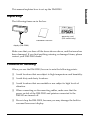
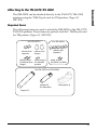
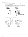
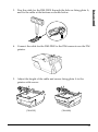
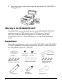
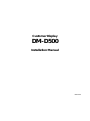
Customer Display
DM-D500
Installation Manual
401156101
CAUTIONS
❏
This document shall apply only to the product(s) identified herein.
❏
No part of this document may be reproduced, stored in a retrieval system, or
transmitted in any form or by any means, electronic, mechanical, photocopying,
recording, or otherwise, without the prior written permission of Seiko Epson
Corporation.
❏
The contents of this document are subject to change without notice. Please
contact us for the latest information.
❏
While every precaution has been taken in the preparation of this document,
Seiko Epson Corporation assumes no responsibility for errors or omissions.
❏
Neither is any liability assumed for damages resulting from the use of the
information contained herein.
❏
Neither Seiko Epson Corporation nor its affiliates shall be liable to the purchaser
of this product or third parties for damages, losses, costs, or expenses incurred
by the purchaser or third parties as a result of: accident, misuse, or abuse of this
product or unauthorized modifications, repairs, or alterations to this product, or
(excluding the U.S.) failure to strictly comply with Seiko Epson Corporation's
operating and maintenance instructions.
❏
Seiko Epson Corporation shall not be liable against any damages or problems
arising from the use of any options or any consumable products other than
those designated as Original EPSON Products or EPSON Approved Products by
Seiko Epson Corporation.
TRADEMARKS
®
EPSON is a registered trademark of Seiko Epson Corporation.
Microsoft®, MS®, MS-DOS®, Windows®, Windows NT® are registered trademarks
of Microsoft Corporation.
General Notice: Other product and company names used herein are for
identification purposes only and may be trademarks of their respective companies.
Copyright © 1999, 2000 by SEIKO EPSON CORPORATION
Precaution Headings
This document uses the two headings shown below to call attention to potential hazards.
Failure to observe the information provided under or alongside these headings may lead
to injury or property damage. Be sure that you understand the meaning of each heading
before you proceed.
WARNING:
Indicates a potentially lethal hazard. Failure to observe a WARNING
may result in severe injury or death.
CAUTION:
Failure to observe a CAUTION may result in personal injury, or in damage
to equipment or other property.
Safety Precautions
WARNING:
❏
Shut down your equipment immediately if it produces smoke, a
strange odor, or unusual noise. Continued use may lead to fire or
electric shock. Immediately turn the power off and contact your
dealer or a SEIKO EPSON service center for advice.
❏
Never attempt to repair this product yourself. Improper repair work
can be dangerous. Tampering with this product may result in injury,
fire, or electric shock.
❏
Be sure to use the specified power source. Connection to an
improper power source may cause fire or shock.
❏
Do not allow foreign matter to fall into the equipment. Penetration
of foreign objects may lead to fire or shock.
❏
If water or other liquid spills into this equipment, immediately turn the
power off and contact your dealer or a SEIKO EPSON service center
for advice. Continued usage may lead to fire or shock.
1
English
Safety Precautions
This document presents important information intended to ensure safe and effective use
of this product. Please read this document carefully, and store it in an accessible location
near your installation.
CAUTION:
❏
Do not plug the cable differently from the instruction in this manual.
Wrong connection may cause equipment damage and fire.
❏
Be sure to set this equipment on a firm, stable, horizontal surface.
Product may be damaged or cause injury if it falls.
❏
Do not use in locations subject to high humidity or dust levels.
Excessive humidity and dust may cause equipment damage, fire, or
shock.
❏
Do not place heavy objects on top of this product. Equipment may
be damaged and cause injury if it falls.
❏
Do not attach plural extension supports. Product may be damaged
or cause injury if it falls.
❏
A stopper limits the horizontal rotation of the display. Do not try to
force it to turn beyond the limits of the stopper. Doing so may
damage the equipment.
EMC and Safety Standards Applied
Product Name: DM-D500
Type Name: M151A
The following standards are applied only to the display that is so labeled. (EMC is tested
using the EPSON PS-170 power supply.)
❏
Europe:
CE Marking
Safety: EN60950
❏
North America:
EMI: FCC/ICES-003 Class A
Safety: UL 1950/CSA C22.2 No.950
❏
Japan:
EMC: VCCI Class A
❏
Oceania:
EMC: AS/NZS 3548 (CISPR22) Class B
JEIDA-52
CE Marking
The display conforms to the following Directies and Norms
Directive 89/336/EEC
2
EN55022 Class B
EN55024
IEC 61000-4-2
IEC 61000-4-3
IEC 61000-4-4
IEC 61000-4-5
IEC 61000-4-6
IEC 61000-4-11
WARNING
English
You are cautioned that changes or modifications not expressly approved by SEIKO
EPSON Corporation could void your authority to operate the equipment.
FCC COMPLIANCE STATEMENT FOR AMERICAN USERS
This equipment has been tested and found to comply with the limits for a Class A digital
device, pursuant to Part 15 of the FCC Rules. These limits are designed to provide
reasonable protection against harmful interference when the equipment is operated in a
commercial environment.
This equipment generates, uses, and can radiate radio frequency energy and, if not
installed and used in accordance with the instruction manual, may cause harmful
interference to radio communications. Operation of this equipment in a residential area is
likely to cause harmful interference in which case the user will be required to correct the
interference at his own expense.
FOR CANADIAN USERS
This Class A digital apparatus complies with Canadian ICES-003.
Cet appareil numérique de la classe A est conforme à la norme NMB-003 du Canada.
About This Manual
Cautions and Notes
CAUTION:
Cautions must be observed to avoid minor injury to yourself or damage
to your equipment.
Note:
Notes have important information and useful tips on the operation of your display.
3
Contents
About This Manual . . . . . . . . . . . . . . . . . . . . . . . . . . . . . . . . . . . . . . . . . . . . . . . . . . . . . . . . 3
Contents . . . . . . . . . . . . . . . . . . . . . . . . . . . . . . . . . . . . . . . . . . . . . . . . . . . . . . . . . . . . . . . . . 4
Unpacking . . . . . . . . . . . . . . . . . . . . . . . . . . . . . . . . . . . . . . . . . . . . . . . . . . . . . . . . . . . . . . . 5
Cautions on Handling. . . . . . . . . . . . . . . . . . . . . . . . . . . . . . . . . . . . . . . . . . . . . . . . . . . . . . 5
Usage . . . . . . . . . . . . . . . . . . . . . . . . . . . . . . . . . . . . . . . . . . . . . . . . . . . . . . . . . . . . . . . . . . . . 6
Precautions when connecting to a TM printer . . . . . . . . . . . . . . . . . . . . . . . . . . . . . . . . . 7
Assembling . . . . . . . . . . . . . . . . . . . . . . . . . . . . . . . . . . . . . . . . . . . . . . . . . . . . . . . . . . . . . . . 8
Attaching to the IR Series . . . . . . . . . . . . . . . . . . . . . . . . . . . . . . . . . . . . . . . . . . . . . . . 8
Attaching to the TM-H5000II/TM-J8000 . . . . . . . . . . . . . . . . . . . . . . . . . . . . . . . . . 10
Attaching to the TM-U375/TM-U950. . . . . . . . . . . . . . . . . . . . . . . . . . . . . . . . . . . . 13
Attaching to the TM-H6000/TM-U675 . . . . . . . . . . . . . . . . . . . . . . . . . . . . . . . . . . 16
Attaching to Other TM Printers . . . . . . . . . . . . . . . . . . . . . . . . . . . . . . . . . . . . . . . . 21
Attaching to the DM-D stand . . . . . . . . . . . . . . . . . . . . . . . . . . . . . . . . . . . . . . . . . . 24
Part Names and Functions . . . . . . . . . . . . . . . . . . . . . . . . . . . . . . . . . . . . . . . . . . . . . . . . . 31
Exterior . . . . . . . . . . . . . . . . . . . . . . . . . . . . . . . . . . . . . . . . . . . . . . . . . . . . . . . . . . . . . 31
DIP Switch . . . . . . . . . . . . . . . . . . . . . . . . . . . . . . . . . . . . . . . . . . . . . . . . . . . . . . . . . . . . . . 32
DIP Switch Functions . . . . . . . . . . . . . . . . . . . . . . . . . . . . . . . . . . . . . . . . . . . . . . . . . 32
Turning and Tilting the DM-D500 . . . . . . . . . . . . . . . . . . . . . . . . . . . . . . . . . . . . . . . . . . 35
Self Test . . . . . . . . . . . . . . . . . . . . . . . . . . . . . . . . . . . . . . . . . . . . . . . . . . . . . . . . . . . . . . . . . 36
Check Items of Self test. . . . . . . . . . . . . . . . . . . . . . . . . . . . . . . . . . . . . . . . . . . . . . . . 36
Performing Self test . . . . . . . . . . . . . . . . . . . . . . . . . . . . . . . . . . . . . . . . . . . . . . . . . . . 36
Specification . . . . . . . . . . . . . . . . . . . . . . . . . . . . . . . . . . . . . . . . . . . . . . . . . . . . . . . . . . . . . 37
General Specifications. . . . . . . . . . . . . . . . . . . . . . . . . . . . . . . . . . . . . . . . . . . . . . . . . 37
Electrical Specifications . . . . . . . . . . . . . . . . . . . . . . . . . . . . . . . . . . . . . . . . . . . . . . . 39
Environmental Specifications . . . . . . . . . . . . . . . . . . . . . . . . . . . . . . . . . . . . . . . . . . 39
Character Specifications . . . . . . . . . . . . . . . . . . . . . . . . . . . . . . . . . . . . . . . . . . . . . . . 40
Reliability Specification . . . . . . . . . . . . . . . . . . . . . . . . . . . . . . . . . . . . . . . . . . . . . . . 40
4
English
This manual explains how to set up the DM-D500.
Unpacking
The following items are in the box.
warranty card
(201 model only)
installation manual
display (DM-D500)
Make sure that you have all the items shown above, and that none has
been damaged. If you find anything missing or damaged items, please
contact your DM-D500 dealer.
Cautions on Handling
When you use the DM-D500, be sure to note the following points:
❏ Avoid locations that are subject to high temperature and humidity.
❏ Avoid dirty and dusty locations.
❏ Avoid locations that are unstable or are subject to high levels of
vibration.
❏ When connecting or disconnecting cables, make sure that the
power switch of the DM-D500 and printers connected to the
DM-500 are turned off.
❏ Do not drop the DM-D500, because you may damage the built-in
vacuum fluorescent display.
5
Usage
The DM-D500 can be used with the following equiment.
❏ IR Series. You can attach the DM-D500 to the IR Series using the
“DM-D pole unit for IR” (DP-504). (See page 8.)
❏ TM-H5000II/TM-J8000 printers. You can attach the DM-D500 to
TM-H5000II/TM-J8000 printers using the “DM-D pole unit for TM
printers (Type B)” (DP-503). (See page 10.)
❏ TM-U375/TM-U950. You can attach the DM-D500 to the TM-U375/
TM-U950 printers using the “DM-D pole unit for TM printers
(Type A)” (DP-502). (See page 13.)
❏ TM-H6000/TM-U675. You can attach the DM-D500 to TM-H6000/
TM-U675 printers using the “DM-D pole unit for TM printers
(Type A)” (DP-502). (See page 16.)
❏ Other TM printers. You can attach the DM-D500 using the “DM-D
pole unit for TM printers (Type A)” (DP-502) and Velcro tapes or
screws. (See page 21.)
❏ DM-D stand. You can attach the DM-D500 to the DM-D stand
directly using the “DM-D stand unit for DM-D500” (DP-501). When
using the DM-D stand, an optional power supply unit (PS-170) is
required. Also, if you want to extend the length of the DM-D500, an
optional extension support unit (DP-105) is required. (See page 24.)
6
When the DM-D500 is connected to a TM printer, be sure to check the serial
number on the label affixed to the rear or bottom of the TM printer. If the serial
number is one of the numbers indicated below it can be used immediately. If
the serial number is not listed below, however, the DM-D500 cannot be
connected to the TM printer as it is. In this case, please purchase and install the
latest model of the UB-S01 board (Part code: C8233610200) before using the
DM-D500 with that printer.
If your TM or other printer is not listed below, it may be connected to the DMD500 without any special modifications (continued on back).
Printer
Model
Serial No.
TM-H5000
None *1
TM-H5000II 001 AR30 010001 and higher
011 AR40 040001 and higher
AR40 530001 and higher
021 AR50 040001 and higher
AR50 510001 and higher
031 AR60 040001 and higher
AR60 510001 and higher
041 AR70 040001 and higher
AR70 510001 and higher
091 BFX0 000001 and higher
BFX0 510001and higher
161 BKS0 000001 and higher
BKS0 510001 and higher
181 BNV0 000001and higher
BNV0 510001and higher
201 B430 000001 and higher
B430 510001 and higher
211 B5X0 000001 and higher
B5X0 510001 and higher
Printer
TM-U590
Model
Serial No.
101 ART0 010001 and higher
111 ARU0 003001 and higher
ARU0 510001 and higher
131 ARY0 003001 and higher
ARY0 510001 and higher
141 BUV0 000001 and higher
BUV0 510001 and higher
TM-H6000 001 BMQ0 020001 and higher
011 BMR0 020001 and higher
021 BMS0 020001 and higher
031 BMT0 020001 and higher
041 BV40 020001 and higher
061 BX50 020001 and higher
071 B7R0 020001 and higher
TM-U675 001 BMK0 020001 and higher
011 BML0 020001 and higher
021 BMM0 020001and higher
061 BX30 020001 and higher
TM-T285
001 2XT0 010001 and higher
TM-J8000 011 AQS0 010001 and higher
*1: If your printer is a TM-H5000, always purchase the latest model of the UB-S01 before using it with
the DM-D500.
If an old model of the UB-S01 (Part code: C8233610000)is connected to the
TM printer, please purchase and install the latest model of the UB-S01 board
(Part code: C8233610200).
The TM printer and UB-S01 used with the DM-D500 will have one of the
following markings on the RS-232C connector mounting plate. This marking
indicates whether of not the printer can be connected to the DM-D500.
Blue seal
Scribed square
7
English
Precautions when connecting to a TM printer
Assembling
Attaching to the IR Series
The DM-D500 can be attached directly to the IR Series using the “DM-D
pole unit for IR” (DP-504).
Required items
The following items are used to attach the DM-D500 to the IR Series.
These items are packed with the “DM-D pole unit for IR” (DP-504).
fixing screws
base
support A
support B
(for extension)
Assembling steps
1. Pass the cable for the DM-D500 through support A, and attach
support A to the DM-D500.
When using support B for extension, insert the tab on support B
into the hole on support A until you feel it click.
When using support B for
extension
8
Note:
When attaching the base, note that the corners of the base are set as shown
below.
3. Pass the cable for the DM-D500 through the base.
4. Insert the tab on the base into the hole on the support until you feel
it click.
.
9
English
2. Attach the base to the setting position on the IR Series, and secure it
with the screws.
5. Connect the cable for the DM-D500 to the DM connector on the IR
Series.
Attaching to the TM-H5000II/TM-J8000
The DM-D500 can be attached directly to the TM-H5000II/TM-J8000
printers using the “DM-D pole unit for TM printers (Type B)” (DP-503).
Required items
The following items are used to attach the DM-D500 to the
TM-H5000II/TM-J8000 printers. These items are packed with the
“DM-D pole unit for TM printers (Type B)” (DP-503).
fixing screws
base
support B
(for extension)
support C
10
English
Assembling steps
1. Pass the cable for the DM-D500 through support C, and attach
support C to the DM-D500.
When using support B for extension, insert the tab on support B
into the hole on support C until you feel it click.
When using support B for
extension
2. Attach the base to the setting position on the TM printer and secure
it with the screws.
11
3. Pass the cable for the DM-D500 through the base.
4. Insert the tab on the base into the hole on the support until you feel
it click.
5. Connect the cable for the DM-D500 to the DM connector on the TM
printer.
12
English
Attaching to the TM-U375/TM-U950
The DM-D500 can be attached directly to the TM-U375/TM-U950
printers using the “DM-D pole unit for TM printers (Type A)”
(DP-502).
Required items
The following items are used to attach the DM-D500 to the TM-U375/
TM-U950 printers. These items are packed with the “DM-D pole unit
for TM printers (Type A)” (DP-502).
<For TM-U950>
<For TM-U375>
rubber feet
(square)
rubber feet
(square)
rubber feet
(large)
fixing screws
fixing screws
for rubber feet for metallic
portion
(large)
fixing screws
for plastic position
<For TM-U375 and TM-U950>
support B
for extension
fixing plate A
support C
13
Assembling steps
1. Pass the cable for the DM-D500 through support C, and attach
support C to the DM-D500.
When using support B for extension, insert the tab on support B
into the hole on support C until you feel it click.
When using support B
for extension
2. Attach the rubber feet to the printer.
[TM-U375]
14
[TM-U950]
4. Connect the cable for the DM-D500 to the DM connector on the TM
printer.
5. Adjust the length of the cable and secure fixing plate A to the
printer with screws.
[TM-U375]
[TM-U950]
15
English
3. Pass the cable for the DM-D500 through the hole on fixing plate A,
and fix the cable at the bottom as shown below.
6. Store any excess cable in the support, and attach the DM-D500 to
fixing plate A.
Attaching to the TM-H6000/TM-U675
The DM-D500 can be attached directly to the TM-H6000/TM-U675
printers using the “DM-D pole unit for TM printers (Type A)”
(DP-502). You can attach fixing plate A on either side of the
TM-H6000/TM-U675. After attaching it, you can slide the display
freely.
Required items
The following items are used to attach the DM-D500 to the TM-H6000/
TM-U675 printers. These items are packed with the “DM-D pole unit
for TM printers (Type A)” (DP-502).
stopper
fixing screws for
rubber feet (small)
support C
16
fixing screw
for stopper
angle fixing
screw
rubber feet (small)
support B
for extension
fixing plate B
fixing screws for
fixing plate B
fixing plate A
English
Assembling steps
1. Pass the cable for the DM-D500 through support C, and attach
support C to the DM-D500.
When using support B for extension, insert the tab on support B
into the hole on support C until you feel it click.
When using support B
for extension
2. Attach the rubber feet to the printer.
3. Attach fixing plate B to the printer.
17
4. Pass the cable for the DM-D500 through the hole on fixing plate A,
and fix the cable at the bottom as shown below.
5. Connect the cable for the DM-D500 to the DM connector on the TM
printer.
6. Attach fixing plate A to the TM printer using the stopper. When
you attach the stopper, insert the projections on the stopper into the
holes of fixing plate B. Fixing plate A can be attached on either side
of the printer. (The illustration below shows fixing plate A attached
to the right side of the printer.)
18
19
English
7. The horizontal rotation mechanism of fixing plate A can be
adjusted. To secure the location of the display, set fixing plate A to
either one of the following four positions and secure it with the
angle fixing screw.
Note:
The paper roll cover may not open if the position of the display is
inappropriate. Before securing the position of the display, make sure that
you can open the paper roll cover.
paper roll cover
8. Store any excess cable in the support and attach the DM-D500 to
fixing plate A.
9. Connect the power cable of the printer. To avoid disconnection,
hook the cable to the tabs on fixing plate B, as shown below.
20
When using with other TM printers, the DM-D500 can be attached to a
desk or other surface, using the “DM-D pole unit for TM printers
(Type A)” (DP-502), and Velcro tapes or screws.
Required items
The following items are used when the DM-D500 is used with other
TM printers. These items are packed with the “DM-D pole unit for TM
printers (Type A)” (DP-502).
Velcro tapes
Velcro tapes
fixing plate A
support B (for extension)
fixing screws for
wood position
support C
Assembling steps using Velcro tapes
1. Attach Velcro tapes to the bottom of fixing plate A.
21
English
Attaching to Other TM Printers
2. Pass the cable for the DM-D500 through support C, and attach
support C to the DM-D500.
When using support B for extension, insert the tab on support B
into the hole on support C until you feel it click.
When using support B
for extension
3. Pass the cable for the DM-D500 through the hole on fixing
plate A, and fix the cable at the bottom as shown below.
4. Connect the cable for the DM-D500 to the DC connector on the
TM printer.
22
6. Peel off the Velcro tapes, and attach the display to the setting
position.
Assembling steps using screws
1. Follow steps 2 and 3 in “Assembling steps using Velcro tapes.”
2. Secure fixing plate A to the setting position with fixing screws.
3. Attach the DM-D500 to fixing plate A.
23
English
5. Store any excess cable in the support, and attach the DM-D500
to fixing plate A.
Attaching to the DM-D stand
The DM-D500 can be attached directly to the DM-D stand using the
“DM-D stand unit for DM-D 500” (DP-501). The DM-D500 with the
DM-D stand can be connected to a TM printer, or be used as a stand
alone product.
Required items
The following items are used to attach the DM-D500 to the DM-D
stand. Note that an optional power unit (PS-170) is required when
using the DM-D stand. Also, another optional extension support
(DP-105) is required if you want to extend the length of the DM-D500.
Please get them separately from the DM-D stand unit (DP-501).
<DM-D stand unit for DM-D500 (DP-501)>
interface connector
DM-D stand
extension cable for
power supply
<extension support (DP-105)>
base plate
RS-232C connector installation screw
(mm type)
<power supply unit (PS-170)>
Velcro tapes
power
supply unit
extension support
24
AC cable
English
Connectors for the DM-D stand
The connectors for the DM-D stand are as follows:
display connector
computer connector
power supply unit connector
printer connector
extension cable connector
Note:
The DM-D stand comes with inch-type hexagonal lock screws installed to
secure the interface cable to the interface connector for RS-232. If you plan to
use an interface cable which requires millimeter-type lock screws, replace the
inch-type screws with the included millimeter-type screws using a hex
screwdriver (5mm). To distinguish the two types of screws, see the illustration
below.
notch (one or more lines)
inch-type
millimeter-type
RS-232C connector
installation screw
25
Jumper setting
Set the jumpers on the DM-D stand as follows:
JP1
JP2
Contents
1-2
1-2
Set the jumpers as in the left columns when connecting both the TM
printer and the DM-D stand. (Default setting)
2-3
2-3
Set the jumpers as in the left column when using the DM-D stand as
stand alone. (TM printer is not connected.)
The jumpers are located as follows:
Precautions on using the power supply unit
To avoid damage to the DM-D500 and the power supply unit, make
sure to note the following points.
❏ Use the optional Seiko Epson products, PS-170, or PA-6508,
PA-6511, PA-6513, PB-6509 or PB-6510 as the power supply.
❏ Never connect the DC cable to the power supply unit when the
power supply unit is connected.
❏ Unplug the DC cable by holding the connector part. If you pull the
cable to unplug, it may be damaged.
26
1. Pass the cable for the DM-D500 through the DM-D stand.
When extending the length of the DM-D stand, attach the extension
support (DP-105) to the DM-D stand.
When using the
extension support
(DP-105)
2.
Insert the tab on the DM-D500 (or the extension support) into the
hole on the DM-D stand until you feel it click.
3. Connect the cable for the DM-D500 to the display connector on the
DM-D stand until you feel it click.
27
English
Assembling steps
4. Connect one end of the computer interface cable to the computer
connector on the DM-D stand; then connect the other end to the
RS-232 connector on the computer. Tighten the screws on both ends
of the cables to fasten them.
computer
5. When using as a stand alone, go to step 6.
When using with the printer, connect one end of the printer
interface cable for the printer to the printer connector on the DM-D
stand; then connect the other end to the connector on the printer.
Tighten the screws on both ends of the cable to fasten them.
printer
28
extension cable
connector
extension cable for
power supply
7. Connect the DC cable of the power supply unit (with the arrow
mark up) to the power supply unit connector indicated with
“POWER IN” on the DM-D stand.
power supply unit
connector
DC cable of power
supply unit
8. When using as a stand alone product, set the jumpers. (See “Jumper
setting” on page 26.)
29
English
6. When not using the extension cable for power supply packed with
the DM-D stand, go to step 7.
When using the extension cable, connect it (with the arrow mark
up) to the extension cable connector indicated with “POWER OUT”
on the DM-D stand; then connect the other end to the power
connector on the printer.
9. Arrange the cables as shown below. Put the cables for the DM-D500
inside the DM-D stand.
10. Attach the base plate to the DM-D stand following the number of
the arrow shown below. At this time, push the base plate until it is
locked by the hook on the DM-D stand.
11. When the extension support (DP-105) is used, attach Velcro tapes to
the four corners of the plate to avoid falling down.
12. Connect the cord of the power unit to the socket.
30
English
Part Names and Functions
Exterior
DIP switch
(rear side of the display)
display
power switch
(bottom of the display)
❏ Display: Characters are displayed.
❏ Power switch: The power is turned on/off.
❏ DIP switch: The functions of the DM-D500 are changed.
(See “DIP switch” for details.)
Note:
When turning on the DM-D500 again after turning it off, wait for at least
3 seconds.
31
DIP Switch
DIP Switch Functions
The DM-D500 has two groups of DIP switches. The functions of the
DIP switches are as follows:
DIP switch 1
DSW1 No.
Function
ON
OFF
Default setting
1-1
Data receive error
Ignored
Displays “?”
OFF
1-2
Hand shaking
XON/XOFF (*1)
DTR/DSR
OFF
1-3
Data length
7 bits
8 bits
OFF
1-4
Parity on or off
Parity
No parity
OFF
1-5
Parity type
Even
Odd
OFF
1-6
1-7
ON
Change transmission speed
See “Transmission speed.”
OFF
1-8
ON
(*1)XON/XOFF is effective only when the DM-D500 is connected with a stand alone.
Transmission speed
SW1-6
SW1-7
SW1-8
Transmission speed (bps)
ON
ON
ON
2400
OFF
ON
ON
4800
ON
OFF
ON
9600
OFF
OFF
ON
19200
ON
ON
OFF
38400
OFF
ON
OFF
57600*
ON
OFF
OFF
115200*
*Cannot be set to 57,600 or 115,200 when using the IR Series.
32
DSW2 No.
Function
ON
OFF
Default setting
2-1
Y-connection (*1)
Enable
Disable
OFF
2-2
Self test selection (*2)
Perform self test
Do not perform
OFF
2-3
20 column and 2 line
mode selection (*3)
20 column and
2 line mode
256 ¥ 64 dots
mode
OFF
2-4
Device selection
default setting
Printer is
selected
Display is
selected
OFF
2-5
Address 0
2-6
Address 1
OFF
2-7
Address 2
The display device number
(1-7) corresponds to Address number 0 to 2.
(All OFF are regarded as no display number.)
2-8
Reserved (*5)
-
OFF
Fixed to OFF
OFF
OFF
(*1)The “Y-connection enable” is set when a TM printer with no modular jack for the
DM-D is connected with this product, using one COM port to connect both TM
printer and DM display. In this case, an optional DM-D stand (DP-501) and a
connecting cable are required. In the cases other than above, choose
“Y-connection disable” (default setting).
(*2)This function can select whether or not you perform self test when turning on the
power. See “Self Test” for details.
(*3)When selecting “20 column and 2 line mode,” this product can be used like the
DM-D105/106/205/206. In this case, the graphic display and the original functions
for the DM-D500 cannot be used, but when selecting “256 × 64 dots mode,” they
can be used.
(*4)When setting to “Printer is selected,” data is sent to the TM printer, but is not
displayed on the display. When setting to “Display is selected,” data is displayed
on the display but is not output from the TM printer.
The selection can be changed using <ESC=> command.
(*5)Stay at OFF setting.
Note:
❏ The changes in the DIP switch setting are effective when the power is
turned on again.
❏ The data transmission setting, such as data length, transmission speed,
must be the same on both your computer and printer.
33
English
DIP switch 2
Setting the DIP switches
CAUTION:
Turn off the DM-D500 while removing the DIP switch cover to
prevent electrical damage to the DM-D500.
1. Turn off the power for the DM-D500.
2. Remove the DIP switch cover.
DIP switch cover
3. Change each setting of the switches with a pointed object, such as a
pen tip or small screwdriver.
4. Close the cover, and turn the power on.
34
You can turn or tilt the display while holding the support. The display
can be moved easily, so do not move any further if it stops. If you move
it by force, you may damage it.
With the “DM-D pole unit for IR” (DP-504) and the “DM-D pole unit
for TM printers (Type B)” (DP-503), the display area maynot face the
direction you desire. In this case, remove the base, change the position
of the tab ob the base so that the display faces to the direction you
desire, and reattach it to the base.
48°
45° for left
(you can turn the same angle for right.)
The display area has the following range of movement:
❏ Tilt: 48° max. (4 steps, 5 positions)
❏ Horizontal rotation: 90° max. (45° for each left and right)
35
English
Turning and Tilting the DM-D5 0 0
Self Test
The DM-D500 has a self test function. If you want to perform a self test,
you must change the setting of the DIP switch.
Check Items of Self test
The following items are checked during the self test:
❏ Control ROM version
❏ DIP switch settings
❏ Example of display characters
❏ Example of each function, such as brightness, flashing, and scroll
Performing Self test
To perform the self test, follow the steps below.
1. Turn off the power for the DM-D500.
2. Set the SW 2-2 of the DIP switch 2 to ON, and turn on the power.
Note:
If the contents of the self test are not displayed, the DM-D500 may be
malfunctioning. Please contact your DM-D500 dealer for assistance.
When the self test is finished and no error occurs, the cursor is
displayed at the home position; then the DM-D500 is ready to receive
data.
36
English
Specification
General Specifications
❏ Height, Width, Depth and Weight
<DM-D500 and DM-D stand>
213 mm
DM-D500
83 mm
65 mm
DM-D stand (DP-501)
51 mm
200 mm
48°
118 mm
90°
•
•
DM-D500:
Height:
Width:
Depth:
Weight:
83 mm
213 mm
51 mm
460 g
DM-D stand (DP-501):
Height:
Width:
Depth:
Weight:
65 mm
200 mm
118 mm
440 g
37
<DM-D pole units>
DM-D pole unit for IR
Series (DP-504)
DM-D pole unit for
TM printer (Type B)
(DP-503)
DM-D pole unit for
TM printers (Type A)
(DP-502)
129 mm
260 mm
248 mm
164 mm
50 mm
base
78 mm
53 mm
38
•
Base and support A of the “DM-D pole unit for IR Series”
(DP-504):
Height:
129 mm
Width:
50 mm
Depth:
53 mm
Weight:
60 g
•
Base and support C of the “DM-D pole unit for TM printers
(Type B)” (DP-503):
Height:
248 mm
Width:
50 mm
Depth:
53 mm
Weight:
116 g
•
Fixing plate A and support C of the “DM-D pole unit for TM
printers (Type A)” (DP-502):
Height:
260 mm
Width:
78 mm
Depth:
164 mm
Weight:
264 g
Max 48° (4 steps, 5 positions)
English
❏ Tilt angle
❏ Horizontal rotation
Max 90° (for each left and right at 45°)
❏ Vacuum fluorescent display
•
Total number of dots:
256 (W) × 64 (H) dots
•
Dot pitch:
0.55 × 0.55 mm
•
Number of characters:
32 column × 4 lines max.
(When using Font A)
•
Number of characters:
42 column × 8 lines max.
(When using Font B)
•
Display color:
Green (505 nm)
•
Brightness:
300 (cd/m2)
Electrical Specifications
❏ Type
PS-170, PA-6508, PB-6509, PB-6510,
PA-6511, PA-6513 (when using the DM-D stand)
❏ Rated voltage DC 11.4 to 48 V
❏ Rated current 0.53 A (at 11.4V) (max.)
Environmental Specifications
❏ Operation environment
Temperature: 5°C to 40°C
Humidity:
30% to 85% (No condensation)
❏ Storage environment
Temperature: −10°C to 50°C
Humidity:
30% to 90% (No condensation)
39
Character Specifications
❏ Type of character
•
Alphanumeric characters: 95
•
International characters:
37
•
Extended graphics:
128 characters × 12 pages
•
Kanji characters (The Kanji character model supports printing
with one of the following character sets.):
Japanese Kanji (JIS Level 1 and 2)
Chinese Kanji (GB2312)
❏ Character grid
•
Font A:
8 × 16 dot
•
Font B:
5 × 7 dot
•
Kanji:
16 × 16 dot
❏ Character style
•
Black/White reverse and emphasis
•
Size change, character spacing, and line spacing
(Only for the window on the graphic mode)
❏ Emulation mode
•
Cursor (except the window on the graphic mode):
DM-D10x emulation
•
Period, comma:
DM-D20x emulation
•
Annunciator:
DM-D20x emulation
Reliability Specification
❏ MTBF (vacuum fluorescent display only)
30,000 hours
(a half-value period of the brightness)
40