1
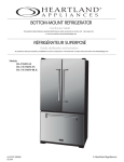
ATRIUM/3 Asymétrique Murale
FR
Mode d’emploi et installation
GB
Instructions for use and installation
Hotte de Cuisine
Cooker Hood
F
SOMMAIRE
GB
CONTENTS
RACCORDEMENT ÉLECTRIQUE
ELECTRICAL WIRING
CONSEILS D’INSTALLATIONS
INSTALLATION ADVICE
POSE DE L’APPAREIL
FITTING THE APPLIANCE
FONCTIONNEMENT
OPERATION
CONSEILS D’UTILISATIONS
USEFUL HINTS
ENTRETIEN
MAINTENANCE
GARANTIE ET SERVICE APRÈS-VENTE
GUARANTEE AND AFTER-SALES-SERVICES
REMARQUES
REMARKS
F
Nous vous remercions de la confiance que vous nous avez accordée en choisissant un appareil de la
gamme ROBLIN.
Celui-ci a fait l’objet de toute notre attention dans sa conception et sa réalisation.
Afin qu’il vous donne entière satisfaction, nous vous recommandons de lire avec attention cette notice qui
vous expliquera comment l’installer, l’utiliser et l’entretenir dans les meilleures conditions.
La présente notice d’emploi vaut pour plusieurs versions de l’appareil. Elle peut contenir des descriptions
d’accessoires ne figurant pas dans votre appareil.
1
RACCORDEMENT ÉLECTRIQUE.
•
La hotte est équipée d’un cordon d’alimentation de type HO5VVF 3 x 0,75 mm² comportant une
fiche normalisée 10/16 A avec système de mise à la terre.
Mode de protection : classe I. Tension d’alimentation : 220-240 V mono - 50Hz / 220 V - 60Hz.
Vérifier que la tension du secteur est identique aux valeurs indiquées sur la plaque signalétique à
l’intérieur de la hotte
•
Si la hotte est raccordée directement sur le réseau sans sa fiche, un interrupteur omnipolaire avec
une ouverture de contact de 3 mm doit être installé avant la hotte. Le fil de terre (Jaune / vert) ne doit
pas être interrompu par cet interrupteur.
2
CONSEILS D’INSTALLATION.
•
Pour un fonctionnement idéal, nous vous conseillons une plage de hauteur de pose qui se situe de
0,65 m à 0,70 m au-dessus du plan de cuisson. Toutefois, il est formellement interdit d’installer toute
hotte ou groupe d’aspiration à une distance inférieure à 0,65 m du plan de travail (risque d’inflammation
des filtres). La fumée doit monter naturellement vers la zone de captation.
•
Respecter le diamètre de sortie de l’appareil : la hotte ne doit en aucun cas être raccordée à un
conduit de ventilation mécanique contrôlée (V.M.C.).
•
Lorsqu’on évacue l’air vicié dans un conduit d’évacuation, veiller à ce que celui-ci ne soit pas déjà
exploité à véhiculer des gaz ou fumées provenant d’appareils alimentés par une énergie autre qu’électrique.
•
Positionner le plan de cuisson au plus près de l’évacuation et éviter la formation de coudes sur la
gaine, afin de réduire au maximum les pertes de charges.
•
Dans tous les cas d’installation, veiller au bon renouvellement d’air de la cuisine. Penser à effectuer une ou des entrées d’air par une grille de section égale ou supérieure au diamètre du tuyau
d’évacuation, afin de ne pas mettre la cuisine en dépression.
•
Prévoir une aération suffisante lorsqu’un appareil de cuisson ou autre utilise simultanément l’air
ambiant de la pièce où est installée la hotte.
•
La dépression maximum crée dans la pièce doit être inférieur à 0.04 mbar, ce qui évite un retour de
gaz de combustion.
•
L’appareil doit être positionné de telle façon que la fiche d’alimentation soit accessible.
•
Cet appareil ne doit pas être utilisé par des personnes (y compris les enfants) ayant des capacités
psychiques, sensorielles ou mentales réduites, ni par des personnes n’ayant pas l’expérience et la
connaissance de ce type d’appareils, à moins d’être sous le contrôle et la formation de personnes responsables de leur sécurité.
1
F
Les enfants doivent être surveillés pour s’assurer qu’ils ne jouent pas avec l’appareil.
3
POSE DE L’APPAREIL.
Montage et raccordement doivent être réalisés par un installateur
ualifi .
(*) Le non-respect de cette condition entraîne la suppression de la garantie du constructeur et
tout recours en cas d’accident.
Attention: prendre bien soin d’employer les chevilles adaptées au support, se renseigner au près
des fabricants, effectuer un scellement si nécessaire. La société décline toute responsabilité en
cas d’accrochage défectueux dû au perçage et chevillage.
4
FONCTIONNEMENT
a) Configuration
Evacuation extérieure ou recyclage :
Votre hotte est programmée pour fonctionner en mode évacuation extérieure. Si vous souhaitez l’utiliser en
la procédure suivante :
Mise en recyclage
x clignotements des 5 leds :
Deux clignotements des 5 leds indiquent l’enregistrement de la mise en recyclage.
Retour en mode évacuation ( L
x clignotements des 5 leds :
Un clignotement des 5 leds indiquera l’enregistrement de la mise en évacuation extérieure.
b) Fonctions de base :
Eclairage :
1
.
1 visualise l’état de l’éclairage
Moteur :
.
la vitesse désirée. Le niveau de vitesse est visualisé par les
de l’accroissement de la vitesse :
Led 2
= niveau minimum
Led 2 et 3 = niveau intermédiaire
Led 2, 3 et 4 = niveau élevé
3 4
ppuyant sur la touche vitesse intensive
3
2
F
(5 ).F
c) Fonctions complémentaires :
• Indication de saturation des filtres m talli ues
heures
bref clignotement de la ed 1
.
3 4
.
.
• Indication de saturation des filtres charbon
heures
brefs clignotements de la ed
s.
1
3 4
5
.
touche
10 secondes.
1 clignotement des Leds 1, 2, 3, 4, et 5 = fonction désactivée.
2 clignotements des Leds 1, 2, 3, 4, et 5 = fonction activée.
• onfiguration r ception t l commande
Votre hotte est programmée pour fonctionner sans réception télécommande. Si vous souhaitez l’utiliser avec
la procédure suivante :
Moteur et éclairage éteints, appuyer sur la touche 1 (éclairage) jusqu’au clignotement de la led 1 :
Deu clignotements de la led indi uent ue la t l commande est activ e.
n clignotement de la led indi ue ue la t l commande est d sactiv e.
Attention, la télécommande doit être équipée de piles alcalines standards : LR003-AAA, 1.5V comme
décrit Fig. 9. Ces piles devraient assurer un usage optimum de longue durée et doivent être positionnées
correctement, elles peuvent exploser si elles sont endommagées ou exposées à la chaleur. Ne pas les
eter dans le feu.
de préserver l’environnement, merci de déposer ces piles dans un conteneur
approprié.
5
ONSEI S D
TI ISATION.
•
Pour obtenir une
maximum d’absorption des fumées ou des vapeurs, faire fonctionner
l’appareil 5 minutes environ avant et après la cuisson des aliments; La première vitesse est conseillée
pour les cuissons à feu doux et pour les sauces. La deuxième pour les cuissons soutenues, grillades et
friteuses. La troisième est indiquée pour les cuissons à forte émanation de graisses et vapeur.
•
IMPORTANT . NE A AIS F A
ER DE
ETS A
DESSO S DE L APPAREIL
•
Les fritures nécessitent une surveillance permanente, l’huile surchauf
nt.
r.
3
F
6
ENTRETIEN.
rvention électrique.
L’appareil a été conçu pour faciliter au maximum les opérations
.
•
, synonyme
fonction-
Nettoyage des filtres m talli ues.
Il est
s
à un NETTOYAGE PÉRIODIQUE
gent
à l’eau
et rinçage) ou au lave- vaisselle (tous les
normale).
•
Remplacement des filtres charbons.
.
.
ces
à la main (avec un
rmois environ pour une utilisation
Retirer les filtres à graisse métalliques.
.
placés.
•
arrosserie.
Nettoyer régulièrement celle-ci en utilisant
.
•
s
its étergents, non
iffons trempés
rture servan
ifs et une éponge légèrement
onduit d vacuation.
6
icié.
prescriptions r glementaires locales
•
.
clairage.
A
Ne pas d passer la puissance prescrite et ne pas changer de type de lampe.
7
.
GARANTIE ET SERVICE APR S-VENTE.
•
En cas d’anomalie de fonctionnement, prévenez votre installateur qui devra
raccordement.
l’appareil et son
•
Dans le cas où un composant électrique viendrait à être endommagé, celui-ci ne peut être remplacé
que par un atelier de réparation reconnu par le fabricant, car des outils spéciaux sont nécessaires.
•
Débrancher complètement l’appareil.
•
Exigez toujours l’utilisation de pièces de rechange d’origine. La non observation de cette prescription
peut compromettre la sécurité de l’appareil.
•
Lors de la commande de pièces détachées, rappeler le numéro de l’appareil inscrit sur la plaque
signalétique située à l’intérieur de la hotte.
•
Seule la facture d’achat de l’appareil fera foi pour l’application de la garantie contractuelle.
Cette garantie ne couvre pas les consommables comme :
- L’éclairage : lampes incandescentes, halogènes ...
.
4
F
8
REMARQUES.
Cet équipement est conforme à la norme européenne sur la basse tension 2006/95/CE relative à la
sécurité électrique et aux normes européennes: 2004/108/CE relative à la compatibilité électromagnétique
et 93/68 relative au marquage CE.
Lorsque ce symbole
d’une poubelle à roue barrée est attaché à un produit, cela
que le
produit est couvert par la Directive Européenne 2002/96/EC. Votre produit est conçu et fabriqué avec
des matériaux et des composants de haute qualité, qui peuvent être recyclés et utilisés de nouveau.
Veuillez vous informer du système local de séparation des déchets électriques et électroniques. Veuillez
agir selon les règles locales et ne pas jeter vos produits usagés avec les déchets domestiques usuels.
Jeter correctement votre produit usagé aidera à prévenir les conséquences négatives potentielles contre
l’environnement et la santé humaine.
9
CONSEILS POUR L’ECONOMIE D’ENERGIE.
Lorsque vous commencez à cuisiner, activer la hotte à la vitesse minimum pour contrôler l’humidité et
éliminer les odeurs de cuisine.
Utilisez la vitesse intensive lorsque cela est strictement nécessaire.
Augmentez la vitesse de la hotte seulement lorsque la quantité de vapeur le requiert.
Veillez à ce que le ou les filtres de la hotte soient toujours propres, afin d’optimiser l’éfficacité
anti-graisse et anti-odeurs.
5
GB
for
We
Before
•
T
,
.
10 16A
.
3
.
c
.
0 40 V
V
2
50
0
60
.
INSTALLATION ADVICE
.
To
65
(for
To
•
•
If
•
If
•
The
•
The
•
•
.
3
hood
•
•
•
of
for
ELECTRICAL
•
•
•
•
for
.
for Use
The
1
.
or 70
of
of
for
cooker hood
cooker hood,
hood
.
rise
cooker hood
.
hood is
of
.
or
of fresh
r.
cooker hood
.
f
.
cooker hood is
The
•
• This
or
0.04
.
is for
is
or
doors
.
is
is
for
,
of
.
or
.
of
e
for
.
or
.
.
3
FITTING
A
IMPORTANT -
6
.
of
.
GB
green / yellow : earth
blue : neutral
brown : live
As the colours of the wires in the mains lead of this appliance may not correspond with the coloured
markings identifying the terminals in your plug, proceed as follows.
- The wire which is coloured green and yellow must be connected to the terminal in the plug which is
or coloured green or green and yellow.
marked with the letter E or by the earth symbol
- The wire which is coloured blue must be connected to the terminal which is marked with the letter N
or coloured black.
- The wire which is coloured brown must be connected to the terminal which is marked with the letter
L or coloured red.
The hood is more effective when used in the extraction mode (ducted to the outside). When the cooker
hood is ducted to the outside, charcoal
are not required.The ducting used must be 150 mm (6
INS), rigid circular pipe and must be manufactured from
retardant material, produced to BS.476
or DIN 4102-B1. Wherever possible use rigid circular pipe which has a smooth interior, rather than
the expanding concertina type ducting.
Maximum length of ducting run:
- 4 metres with 1 x 90° bend.
- 3 metres with 2 x 90° bends.
- 2 metres with 3 x 90° bends.
The above assumes our 150 mm (6 INS) ducting is being installed. Please note ducting components and
ducting kits are optional accessories and have to be ordered, they are not automatically supplied
with the chimney hood.
7
GB
4
OPERATION
A - EXTRACTION OR RECYCLING :Your cooker hood is supplied in the extraction mode. To use the cooker
hood in the recycling mode re-programme the hood as follows:
Starting in the recycling mode (the contaminated air passes into the hood through the grease filters and
the purifying activated charcoal filter and back out into the kitchen through grilles).
Press the ‘+’ button (while the motor and lights are switched ‘OFF’) until the five LED lights will flash twice
to indicate confirmation that the cooker hood is in the recycling mode.
Reverting to the extraction mode (The cooker hood is ducted to the outside).
Press the ‘+’ button (while the motor and lights are switched ‘OFF’) until the five LED lights will flash once
to indicate confirmation that the cooker hood is in the extraction mode.
GB
B - BASIC INSTRUCTIONS
Lighting
Press LED button 1 to switch ‘ON’ the lights and the LED will illuminate to confirm the lights are switched
‘ON’.
Motor
Press LED button 2 to switch ‘ON’ the fan motor (and adjust the speed of the fan motor by pressing the
LED button ‘+’ and ‘-‘) and the LED lights 2, 3 and 4 will illuminate. The fan speed will be increased if
constant pressure is kept on the (+) button.
LED 2
: Minimum speed - cooking with one pan or simmering
LED 2 & 3 : Medium speed - normal cooking with up to 4 pans
LED 2, 3 & 4 : Maximum speed - frying and cooking foods with strong odours
Press LED button 5 to obtain the boost position for maximum effect and the LED will illuminate to confirm
fan is switched ‘ON’.
C - COMPLEMENTARY INSTRUCTIONS
• Indication of saturation of the metal grease filters :
After 200 hours use, one quick flash of the LED 1 will indicate that you must clean the metal grease
filters. (See chapter on ‘Maintenance’).
To reset the 200 hours timer back to zero requires the motor and lights must be switched ‘OFF’; then and
proceed as follows:
Press the LED button ‘+’ for 3 to 4 seconds and the LED lights 1,2,3, 4 and 5 will flash to confirm the
programme has been reset to zero.
8GB
• Indication of saturation of the active charcoal filter :
After 400 hours use, two quick flash of the LED 1 will indicate that you must replace the active charcoal
filter and clean the metal grease filters. (See chapter on ‘Maintenance’).
To reset the 400-hour timer the motor and lights must be switched ‘OFF’.
Push the LED button ‘+’ for 10 seconds.
One flash of the LED lights 1,2,3,4 and 5 = function is switched ‘OFF’.
Two flashes of the LED lights 1,2,3,4 and 5 = function is switched ‘ON’.
8
GB
• Pre-set remote control handset
Your cooker hood is supplied with a deactivated remote control receiver. To use the cooker hood with a
remote control re-programme the hood as follows:
Press the LED button (Lighting) ‘1’ while the motor and lights are switched ‘OFF’, until the LED lights 1 will
flash to confirm the programme has been activated :
One flash of the LED lights 1 = function is switched ‘OFF’.
Two flashes of the LED lights 1 = function is switched ‘ON’.
Caution, the remote control handset must be fitted with standard LR03-AAA size 1.5V zinc-carbon alkaline
batteries as illustrated Fig. 9. These batteries should give a long life and constant discharge throughout their
life. These batteries must be disposed of properly and could explode if damaged or exposed to heat.
Do not dispose of on fire. Dispose of batteries in the appropriate sort container to protect the environment.
5
USEFUL HINTS
• To obtain the best performance we recommend you to switch ‘ON’ the cooker hood a few minutes (in
the boost setting) before you start cooking and you should leave it running for approximately 15 minutes
.
•
IMPORTANT: NEVER DO FLAMBÉ COOKING UNDER THIS COOKER HOOD
•
Do not leave frying pans unattended during use as over-heated fat and oil might catch fire.
•
Do not leave naked flames under this cooker hood.
•
Switch ‘OFF’ the electric and gas before removing pots and pans.
•
Ensure heating areas on your hotplate are covered with pots and pans when using the hotplate
and cooker hood simultaneously.
9
GB
6
MAINTENANCE
Before carrying out any maintenance or cleaning isolate the cooker hood from the mains supply.
The cooker hood must be kept clean; a build up of fat or grease may cause a fire hazard.
Casing
• Wipe the cooker hood frequently with a clean cloth, which has been immersed in warm water containing a mild detergent and wrung out.
• Never use excessive amounts of water when cleaning particularly around the control panel.
• Never use scouring pads or abrasive cleaners.
• Always wear protective gloves when cleaning the cooker hood.
Metal Grease Filters : The metal grease filters absorb grease and dust during cooking in order to keep
clean the cooker hood inside. The grease filters should be cleaned once a month or more frequently if
the hood is used for more than 3 hours per day.
To remove and replace the metal grease filters
• Remove the metal grease filters one at a time by releasing the catches on the filters; the filters can
now be removed.
• The metal grease filters should be washed, by hand, in mild soapy water or in a dishwasher.
• Allow to dry before replacing.
Active Charcoal Filter : The charcoal filter cannot be cleaned. The filter should be replaced at least
every three months or more frequently if the hood is used for more than three hours per day.
To remove and replace the filter
• Remove the metal grease filters.
• Press against the two retaining clips, which hold the charcoal filter in place and this will allow the filter
to drop down and be removed.
• Clean the surrounding area and metal grease filters as directed above.
• Insert the replacement filter and ensure the two retaining clips are correctly located.
• Replace the metal grease filters.
Extraction tube : Check every 6 months that the dirty air is being extracted correctly. Comply with local
rules and regulations with regard to the extraction of ventilated air.
Lighting : If the lamp fails to function check to ensure it is fitted correctly into the holder. If lamp failure
has occurred then it should be replaced with identical replacement.
Do not replace with any other type of lamp and do not fit a lamp with a higher rating.
10
7
GUARANTEE AND AFTER SALES SERVICE
• In the event of any malfunction or anomaly, notify your fitter who will have to check the appliance and its connection.
• In the event of damage to the mains supply cable, this can only be replaced by at approved repair
centre appointed by the manufacturer who will have the required tools and equipment to carry out any
repairs properly. Repairs carried out by other persons will invalidate the guarantee.
• Use only genuine spare parts. Should these warnings fail to be observed it could affect the safety of
your cooker hood.
• When ordering spare parts quote the model number and serial number written on the rating plate,
rs inside the hood.
• Proof of purchase will be required when requesting service. Therefore, please have your receipt
available when requesting service as this constitutes the date from which your guarantee commenced.
This Guarantee does not cover :
- Damage or calls resulting from transportation, improper use or neglect, the replacement of any light
c.
These items are considered to be consumable under the terms of this guarantee.
8
REMARKS
This appliance complies with European regulations on low voltages Directive 2006/95/CE on electrical
safety, and with the following European regulations: Directive 2004/108/CE on electromagnetic compatibility and Directive 93/68 on EC marking.
When this crossed-out wheeled bin symbol
is attached to a product it means the product is covered by the European directive 2002/96/EC.Your product is designed and manufactured with high quality
materials and components, which can be recycled and reused.Please inform yourself about the local
separate collection system for electrical and electronic product. Please act according to your local rules
and do not dispose of your old products with your normal household waste. The correct disposal of your
old product will help prevent potential negative consequences for the environment and human health.
9
ENERGY SAVING TIPS.
When you start cooking, switch on the range hood at minimum speed, to control moisture and remove
cooking odor.
Use boost speed only when is strictly necessary.
Increase the range speed only when the amount of vapor makes it necessary.
Keep range hood filter(s) clean to optimize grease and odor efficiency.
11
ECLAIRAGE
LIGHTING
BELEUCHTUNG
2 X LEDS 1 W
Red
Purple
Brown
Blue
L2 F
Green-Yellow
L1
N
PWM
motor
Yellow
Blue
MULTI-FLACH KABEL
LIMANDE COMMANDE
FLAT CABLE
7 8
Brown
Maj (Update)
01/01/2015
Page
1/1
FERNBEDIENUNG
RECEPTEUR INFRAROUGE
REMOTE CONTROL
M
100 W
ELEKTRONISCHE STEUERUNG
BOITIER COMMANDE
PUSH BUTTON PANEL
Yellow
A - AZUR - AZUR - AZUR BLAU
BK - BLACK - NOIR- SCHWARZ
B - BLUE - BLEU - BLAU
Br - BROWN - BRUN - BRAUN
G-Y- GREEN YELLOW - VERT JAUNE - GRÜN GELB
Gr - GREY - GRIS - GRAU
L B - LIGHT BLUE - BLEU CLAIR - HELL BLAU
P - PINK - ROSE - ROSA
V - PURPLE - MAUVE - MALVER FARBIG
R - RED - ROUGE - ROT
W - WHITE - BLANC - WEISS
W-P - WHITE PINK - BLANC ROSE - WEISS ROSA
Y - YELLOW - JAUNE - GELB
Blue
7 8
Green-Yellow
Blue
Désignation
ATRIUM 3 Assymetrique Murale
3S_Atrium Assymetrique_M_150101
UK ELECTRICAL CONNECTION
ELECTRICAL REQUIREMENTS
Any permanent electrical installation must comply
with the latest I.E.E. Regulations and local Electricity
Board regulations. For your own safety this should be
undertaken by a qualified electrician e.g. your local
Electricity Board, or a contractor who is on the roll of
the National Inspection Council for Electrical
Installation Contracting (NICEIC).
ELECTRICAL CONNECTION
Before connecting to the mains supply ensure that
the mains voltage corresponds to the voltage on the
rating plate inside the cooker hood.
This appliance is fitted with a 2 core mains cable and
must be permanently connected to the electricity supply
via a double-pole switch having 3mm minimum contact
gap on each pole. A Switched Fuse Connection Unit
to BS.1363 Part 4, fitted with a 3 Amp fuse, is a
recommended mains supply connection accessory to
ensure compliance with the Safety Requirements
applicable to fixed wiring instructions.
The wires in this mains
lead are coloured in
accordance with the
following code:
Green-Yellow
Earth
Blue
Neutral
Brown
Live
As the colours of the wires
in the mains lead of this
appliance may not
correspond with the
coloured markings
identifying the terminals in
your connection unit,
proceed as follows:The wire which is coloured blue must be connected
to the terminal which is marked with the letter ‘N’ or
coloured black.
The wire which is coloured brown must be connected
to the terminal which is marked with the letter ‘L’ or
coloured red.
CH
Fiche de sécurité class 1, 250 V~ 10A
2 poles + terre.
Stecker der Schutzklasse 1, 250 V~ 10A
Zweipolig mit Schutzkontakt (Erde).
Spira di sicurezza classe 1, 250 V~ 10A
2 poli + terra
SEV 1011, SN416534-2, CH-Typ 12
500
650 min
108
40
536
30
Ø150
898
min 776 - Max 1005
256
25
119
41
378
265
212
227
Composants - Components
7a
4
4
R
2
7b
5
8
2
9
2
Pose de l’appareil - Fitting
N°1
N°2
N°5
N°3
N°6
9
2
N°4
Pose de l’appareil - Fitting
4
4
R
2
LED : 2 x 1.1 W
press
or
press*
* Il est nécessaire de déposer le support éclairage sur certain produit,
pour accéder au dos du spot
* It is necessary to remove the light holder on certain product,
to access the back of the spot
FRANKE France S.A.S.
25 Rue des Rosiers - Sainte Cécile
B. P. 60056
50800 VILLEDIEU-LES-POËLES - France
Tél. 02 33 91 26 50 - Fax 02 33 51 54 79 - e-mail : [email protected]
For outside France : Tel. +33 (0)2 33 91 26 57 - Fax. : +33 (0)2 33 51 54 79
e-mail : [email protected]
991.0347.683 - 01.01.2015