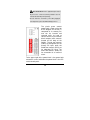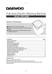
1
8-port 10/100Base-TX
+2-port 100Base-FX
Switch
(INS-802 / INS-802W)
User Manual
COPYRIGHT
All rights reserved. No part of this publication may be reproduced,
stored in a retrieval system, or transmitted in any form or by any means,
whether electronic, mechanical, photo copying, recording or otherwise,
without the prior written permission of the publisher.
FCC WARNING
This equipment has been tested and found to comply with the
limits for a class A device, pursuant to part 15 of FCC rules.
These limits are designed to provide reasonable protection against
harmful interference in a commercial installation. This equipment
generates, uses and can radiate radio frequency energy and, if not
installed and used in accordance with the instructions, may cause
harmful interference to radio communication. Operating this equipment
in a residential area is likely to cause harmful interference, in which
case the user will be required to correct the interference at the user’s
own expense.
CE
This is a Class A product. In a domestic environment, this
product may cause radio interference in which case the user
may be required to take adequate measures.
Take special care to read and understand all content given in the
warning boxes
Warning
TABLE
OF
C ONTENTS
ABOUT THIS GUIDE............................................................ 4
TERMS/USAGE ....................................................................... 4
INTRODUCTION ................................................................... 4
INDUSTRIAL ETHERNET TECHNOLOGY .................................. 5
SWITCHING TECHNOLOGY ..................................................... 5
FEATURES .............................................................................. 6
INS-802 INDUSTRIAL SWITCH – UNPACKING AND
SET-UP ................................................................................... 7
UNPACKING ........................................................................... 7
LAYOUT OF THE INS-802/802W............................................ 8
DIN RAIL MOUNTING OF THE INS-802/802W..................... 10
REDUNDANT POWER INPUTS ................................................ 11
CONFIGURING DC POWER INPUTS ........................................ 11
ETHERNET CONNECTIONS .................................................... 13
LED INDICATORS ................................................................ 14
EXTERNAL ALARM CONTACT .............................................. 15
DIP SWITCH SETTINGS ........................................................ 16
FIBER CONNECTOR .............................................................. 17
AUTO-NEGOTIATION ............................................................ 17
SWITCHING, FILTERING, AND FORWARDING ........................ 18
PORT SPEED & DUPLEX MODE ............................................ 18
TECHNICAL SPECIFICATIONS ...................................... 19
APPENDIX ........................................................................... 21
A BOUT T HIS G UI DE
The INS-802/INS-802W Industrial Series Switch is a hardened,
8-port Ethernet Switch with dual fiber uplinks and redundant DC
power inputs – to provide a reliable and economical solution for
your industrial Ethernet environment. With its dry contact smart
alarm, the INS-802/802W can initiate a physical alarm (audible
and/or visible) in the event of a malfunction. The Switch
operates in a wide temperature range, from -10°C to 70°C
(from -40°C in the case of the 802W), and is designed to handle
higher than normal degrees of vibration and shock, making it
suitable for harsh industrial environments.
This manual discusses how to install the INS-802/INS-802W
Industrial Fast Ethernet Switch.
The INS-802W is able to operate in a wider temperature range
(from -40°C to 70°C). The rest of the features and functions are
the same as the INS-802.
Terms/Usage
In this guide, the term “Switch” (first letter uppercase) refers to
the INS-802/802W Industrial Fast Ethernet Switch, and ”switch”
(first letter lowercase) refers to all other Ethernet switches.
In this guide, the term INS-802 will also refer to the INS-802W.
I NTRODUCTION
This chapter describes the features of the Switch and some
background information about Ethernet/Fast Ethernet switching
technology.
4
Industrial Ethernet Technology
The growing importance of Ethernet has extended to the factory
floor and industrial environments, where things have become
too harsh for typical commercial-grade networking equipment.
VOLKTEK has created an Industrial Series of Switches and
interconnecting devices specifically for the purpose of extending
Ethernet to the factory floor and industrial environments. All of
our Industrial Series devices are delivered in a rugged,
hardened case and with components capable of withstanding a
high degree of vibration and shock. These devices also operate
well in temperatures as high as 70°C.
Not an ordinary office switch by any means, the INS-802 is
engineered and designed specifically for the harsh, industrialtype environments commonly encountered in heavy industry.
With its redundant DC power inputs and high-performance
components, the INS-802 is perfectly suited for the industrial
Ethernet.
Switching Technology
One way to push the limits of Ethernet technology, is the
development of switching technology. A switch bridges Ethernet
packets at the MAC address level of the Ethernet protocol that
are transmitted between connected Ethernet or Fast Ethernet
LAN segments.
Switching is a cost-effective way of increasing the total network
capacity available to users on a local area network. A switch
increases capacity and decreases network loading by dividing a
local area network into different segments which don’t compete
with each other for network transmission capacity.
5
Features
The Switch was designed for easy installation and high
performance in an industrial environment where vibration, shock,
heat, and RF interference may be commonplace.
The Switch was specifically designed to be small and compact
for easy DIN-rail mounting and it can be installed where space
is limited.
The Switch is ideal for deployment with multiple high-speed
servers for shared-bandwidth 10Mbps or 100Mbps workgroups.
With a maximum bandwidth of 200Mbps (100Mbps full-duplex
mode), any port can provide workstations with a congestion-free
data pipe for simultaneous access to the server.
The Switch can be expanded by cascading two or more
switches together in a ‘daisy chain’. As all ports support
200Mbps (half-duplex), the Switch can be cascaded from any
port and to any number of switches.
The Switch combines dynamic memory allocation with storeand-forward switching to ensure that the buffer is effectively
allocated for each port, while controlling the data flow between
the transmit and receive nodes to guarantee against all possible
packet loss.
The Switch is an unmanaged 10/100Mbps Fast Ethernet Switch
that offers solutions for increasing the bandwidth and speed of
small Ethernet workgroups.
Other features are:
o Eight (8) 10/100Base-TX and Two (2) 100Base-FX (SFPtype fiber transceivers)
o Rugged, hardened IP30 Case
o Vibration/Shock operational
6
o
o
o
o
o
o
o
o
Power terminal block
Wide voltage range: 9-48V
DIP Switch to enable or disable alarm functions
Power-input polarity protection function
Under-power and over-power detection function
Wide operating temp.: -10°C - 70°C / -40°C - 70°C (802W)
Store-and-forwarding
Auto-negotiation at all copper ports
INS-802 I NDUSTRIAL S WITCH –
U NPACKI NG AND S ET- UP
This section and the following sections explain the set-up
and installation of the VOLKTEK INS-802/802W
Industrial Switch.
Unpacking
Open the box of the Switch and carefully unpack it. The
box should contain the following items:
One INS-802 8-port 10/100TX plus dual fiber uplink
Industrial Fast Ethernet Switch
One DIN-rail bracket
Protective caps for unused ports
Quick Installation Guide
This User’s Guide CD
If any item is found missing or damaged, please contact
your local reseller for replacement.
7
Layout of the INS-802/802W
Front View of Switch
1. Fiber Port Offline LED x 2
2. Fiber Port LNK/ ACT x 2
3. Fiber 100Mbps LED x 2
4. Primary Power LED
5. Redundant Power LED
6. Alarm LED
7. 2 x 100Base-FX LC Fiber
slots (SFP-type)
8. 10/100Base-TX ports (8)
9. TX Port 100Mbs LED
10. TX Port LNK/ ACT LED
3 21
4
5
6
7
8
9
10
8
TOP View of Switch
Grounding
Screw
Terminal block for
power input
(PWR/RPS), and alarm
dry contact
DIP Switches
Back View of Switch
Din Rail
Bracket
Screws
9
DIN Rail Mounting of the INS-802/802W
The aluminum DIN-rail attachment plate should already
be affixed to the back panel of the Switch. If you need to
attach the DIN-rail plate, assure that the stiff metal spring
is situated towards the top. Attaching the Switch to the
DIN-rail is easy: just align and hook it over the top rail,
making sure that the metal spring (thin bent rod) is in
front of the rail edge as the rail edge bites into the space
behind this spring, then press down and press the
Switch forward to snap into the bottom rail, as shown in
the figures below.
The set-up of the Switch can be performed after checking
the following facts:
•
•
The hanging structure must support at least 1.0 Kg
for the Switch.
The power outlet should be within 1.82 meters (6 feet)
10
•
•
from the Switch.
Visually inspect the DC power jack and make sure
that it is fully secured to the power adapter.
Make sure that there is proper heat dissipation from
and adequate ventilation around the Switch. Do not
place heavy objects on the Switch.
Grounding the INS-802 Industrial Switch will help minimize
noise due to electromagnetic interference (EMI). Always run the
ground connection from the ground screw to the grounding surface
prior to connecting DC power.
Redundant Power Inputs
The primary and redundant power inputs can both be
connected simultaneously to live DC power sources. If
one power source fails, the other source acts as a backup, and automatically supplies the Switch’s power needs.
Configuring DC power Inputs
DC power to the Terminal Block Receptor can be
configured like this:
11
DC Powered Switch: Power is supplied through an external
DC power source. Check the technical specification section for
information about the DC power input voltage.
Since the switch does not include a power switch, plugging its
power adapter into a power outlet will immediately power it on.
The plastic green contact
power block (shown at the top
of the diagram on the left) is
composed of six contact pins
and can be inserted and
removed easily by hand to
connect to the six-pin terminal
block receptor (male contacts
located on the body of the
Switch). The top two contacts
(PWR) are designated for the
primary DC input, while the
middle two contacts (RPS) are
for redundant DC input. The
lower two contacts (ALM) are
for connection to an external
alarm.
To the upper right of the power block is the ground wire
connection screw, and below the power block is the DIPswitch control panel.
12
Procedure for Connecting DC Power:
For shipping, the removable green Contact Block may be
detached from the six-pin terminal contact point. It may
be easier to attach the DC wires to the green Contact
Block if it has first been unplugged from the terminal
contact point on the switch.
A. On the Power Contact Block, use a flathead
screwdriver to loosen the screws of the primary
power pins (labeled PWR +/-) and then insert the
negative and positive DC wires. Tighten until
snug.
B. For the back-up DC connection, follow the same
procedure as above. Attach power wires to the
Contact Block (in the position marked RPS +/-)
C. If the Contact Block is not already inserted into
the block receptor of the Switch, do so now.
D. Assure your DC power supply is stable and clean
before applying DC power to the Switch.
Ethernet Connections
The INS-802 Industrial Fast Ethernet Switch has eight
10/100Base-TX Ethernet ports, and two 100 Base-FX LC
SFP-type connector fiber ports. The 10/100Base-TX
ports are located on the Switch’s front panel and are
13
used to connect to Ethernet-enabled devices. The Fiber
ports use LC SFP-type Single-mode or Multi-mode
modules, which are sold separately.
LED Indicators
Switch Status LED
Power Indicator (PWR) / Redundant Power Supply
(RPS)
These LEDs light green when the Switch is receiving
power from these sources. Otherwise, they are off.
Alarm (ALM)
This indicator will light red and will initiate a physical
alarm (if such an alarm is connected) if a link failure
occurs on any port. It will also be activated if the primary
power source fails.
Port Status LEDs
Fiber ports on the INS-802 are designated as ports 9 and
10 and are represented by 3 LEDs for each of the 2 ports:
100
Indicates 100Mbps speed
on that fiber uplink
LNK/ACT
Illuminates green during
normal link and activity
Fiber Port OFF-LINE LED
Illuminates red when SFP
module is absent
14
10/100Base-TX ports
There are two eagle-eye LED’s on each 10/100 port. The
top LED will illuminate green if the link speed is 100Mbps,
and the lower LED will illuminate green if there is link
activity. Otherwise, the LED’s will be off.
External Alarm Contact
The INS-802 Industrial Switch has one Alarm Contact
connection point located on the green Power Contact
Block on the top panel. For detailed instructions on how
to connect the Alarm Contact power wires to the two ALM
contacts of the 6-contact terminal block connector, see
the Procedure for Connecting DC Power in the section
above (it is the same procedure).
You can connect the Alarm circuit to any warning device
which the user’s factory or industry already has installed
in the control room or factory floor. When a fault occurs,
the Switch will send a signal through the Alarm contact,
to activate this external alarm. The Alarm Contact has
two terminals that form a Fault circuit for connecting to an
alarm system.
An alarm will be signaled in the following situations:
1. Ports 1~8: link failure (e.g.: cable disconnected,
device breakdown, etc.)
15
2. Ports 9~10: link failure (e.g.: cable disconnected,
device breakdown, etc.)
Note: The alarm function is disabled when the
SFP fiber module is absent.
3. PWR/RPS: Power failure
a. Power cord is disconnected, power
supply malfunction, etc.
b. Input power is out of the range listed in
the spec (9 ~ 48V)
DIP Switch Settings
DIP-switches allow for the user to manually turn ON/OFF
any port, the external Alarm, or the redundant power
supply. The figure below shows the DIP-switch control.
DIP 1 (PWR) Controls the primary power
external alarm input. Default is ON.
DIP 2 (RPS) controls the redundant power
external alarm input. Default is ON.
DIP 3-12 represents the alarm for port
numbers of the INS-802 Switch respectively.
Move the DIP switch to the ON position to
manually enable the alarm function. Default is
OFF.
16
Recommended Procedure for configuring and setting
DIP switches during initial installation:
1. Turn all DIP switches OFF.
2. Install the INS-802 into your network.
3. Decide which port(s) need to be monitored or
should trigger the alarm.
4. Turn the corresponding port DIP-switch ON.
5. Activate the Switch.
Fiber Connector
The dual Fiber Ports on the INS-802 are LC-type SFP
modules in either multi-mode or single mode (sold
separately). The Switch’s fiber switched ports operate at
a fixed 100Mbps speed and full-duplex mode to provide
the best performance.
When plugging the LC-type SFP module into the port,
make sure the module is aligned correctly and press the
module into the receptor so that it fits snugly into the port.
The 100Base-FX and the 10/100Base-TX ports are all
fully switched ports, with the dual fiber uplinks providing a
high bandwidth, daisy-chainable backbone connection
that supports long fiber cable distances (up to 2km for
multi-mode, and 60km for single mode).
Auto-negotiation
The INS-802 Industrial Switch’s 10/100Mbps switched
RJ-45 ports auto-negotiates with connected devices to
17
determine the fastest data transmission rate supported
by both devices. This helps make the Switch a plug-andplay device. The Switch’s RJ-45 ports support full or half
duplex, depending on which transmission speed is
supported by the attached device.
Switching, Filtering, and Forwarding
Packets entering the INS-802 Switch with source and
destination addresses belonging to the same port
segment will be filtered, limiting those packets to one port,
and relieving the rest of the network from the need to
process them. A packet with a destination address
served by another port segment will be forwarded to the
appropriate port, and will not be sent to the other ports
where it is not needed. Packets that are used to maintain
network operations (such as the occasional multi-cast
packet) are forwarded to all ports.
As with all VOLKTEK switches, the INS-802 Industrial
Switch operates in the store-and-forward switching mode,
which eliminates bad packets and enables peak
performance to be achieved when there is heavy traffic
on the network.
Port Speed & Duplex Mode
After a cable is plugged into a specific port, the system
uses auto-negotiation to determine the transmission
18
mode for the new twisted-pair connection:
If the connected device does not support auto-negotiation
or has auto-negotiation disabled, an auto-sensing
process is initiated to select the speed and set the duplex
mode to half-duplex.
T ECHNICAL S PECIFICATIONS
General
Standards
IEEE 802.3
IEEE 802.3u & IEEE 802.3x
Connectors
8 (eight) 10/100BaseTX RJ45
2 (two) SFP (LC) Fiber Connectors
Wavelength
1310nm (multi-mode)
1310/1550nm (single mode)
Max Distances
RJ-45 – 100 meters
Fiber Optic – Up to 120,000 meters
Ports
8x 10/100Mbps auto-negotiation, auto MDI-X ports
2x 100Mbps Full duplex (Fiber ports)
19
Physical and Environmental
DC inputs
9-48V DC
Temperature
Operating: -10° ~ 70° C, Storage: -20° ~ 80° C
(INS-802W)
Operating: -40°° ~ 70°° C, Storage: -40°° ~ 85°° C
Humidity
Operating: 5% ~ 85%
Dimensions
120 x 50 x 162 mm (D x W x H)
Compliance
FCC Class A, CE approved
Performance
Transmission
Method:
Store-and-forward, with IEEE802.3x full duplex,
non-blocking flow control.
Fiber ports do not support flow control
Packet
Filtering/Forwar
ding Rate:
MAC Address
Learning:
10Mbps Ethernet: 14,880/pps
100Mbps Fast Ethernet: 148,800/pps
Automatically updated
20
A PPENDIX
RJ-45 Pin Specification
The RJ-45 ports in the Switch support auto-negotiation
and auto MDI/MDI-X. This feature eliminates worries
about using a specific cable type. The pin assignment is
for the user’s reference:
21
The standard cable, RJ-45 pin assignment
The standard RJ-45 receptacle/connector
VOLKTEK CORPORATION
4F, No. 192 Lian-Cheng Road
Chung-Ho, Taipei 235, Taiwan ROC
TEL: +866 (2) 8242-1000
FAX: +886 (2) 8242-3333
ISO 9001 Certified
22