1
User Guide
SBV5220 VoIP Cable
Modem
Introduction
Installation
Troubleshooting
Glossary
License
Safety and Regulatory Information
WARNING: TO PREVENT FIRE OR SHOCK HAZARD, DO NOT EXPOSE THIS PRODUCT TO RAIN OR
MOISTURE. THE UNIT MUST NOT BE EXPOSED TO DRIPPING OR SPLASHING. DO NOT PLACE OBJECTS
FILLED WITH LIQUIDS, SUCH AS VASES, ON THE UNIT.
CAUTION: THIS PRODUCT WAS QUALIFIED UNDER TEST CONDITIONS THAT INCLUDED THE USE OF
THE SUPPLIED CABLES BETWEEN SYSTEMS COMPONENTS. TO ENSURE REGULATORY AND SAFETY
COMPLIANCE, USE ONLY THE PROVIDED POWER AND INTERFACE CABLES AND INSTALL THEM PROPERLY.
CAUTION: DIFFERENT TYPES OF CORD SETS MAY BE USED FOR CONNECTIONS TO THE MAIN SUPPLY
CIRCUIT. USE ONLY A MAIN LINE CORD THAT COMPLIES WITH ALL APPLICABLE PRODUCT SAFETY
REQUIREMENTS OF THE COUNTRY OF USE.
CAUTION: TO REDUCE THE RISK OF FIRE, USE ONLY NO. 26 AWG OR LARGER UL LISTED OR CSA
CERTIFIED TELECOMMUNICATION LINE CORD, OR NATIONAL EQUIVALENT.
CAUTION: INSTALLATION OF THIS PRODUCT MUST BE IN ACCORDANCE WITH NATIONAL WIRING
CODES AND CONFORM TO LOCAL REGULATIONS.
CAUTION: DO NOT OPEN THE UNIT. DO NOT PERFORM ANY SERVICING OTHER THAN THAT CONTAINED
IN THE INSTALLATION AND TROUBLESHOOTING INSTRUCTIONS. REFER ALL SERVICING TO QUALIFIED
SERVICE PERSONNEL.
CAUTION: CHANGES AND MODIFICATIONS NOT EXPRESSLY APPROVED BY MOTOROLA FOR
COMPLIANCE COULD VOID USER’S AUTHORITY TO OPERATE THE EQUIPMENT.
IMPORTANT SAFETY INSTRUCTIONS: When using your telephone equipment, basic safety precautions should
always be followed to reduce the risk of fire, electric shock and injury to persons, including the following:
•
Read all of the instructions listed here and/or in the user manual before you operate this equipment. Give
particular attention to all safety precautions. Retain the instructions for future reference.
•
This device must be installed and used in strict accordance with manufacturer’s instructions as described in
the user documentation that comes with the product.
•
Comply with all warning and caution statements in the instructions. Observe all warning and caution symbols
that are affixed to this equipment.
•
Do not use this product near water for example, near a bathtub, washbowl, kitchen sink or laundry tub, in a
wet basement, or near a swimming pool.
•
Do not overload outlets or extension cords, as this can result in a risk of fire or electric shock. Overloaded AC
outlets, extension cords, frayed power cords, damaged or cracked wire insulation, and broken plugs are
dangerous. They may result in a shock or fire hazard.
•
Route power supply cords so that they are not likely to be walked on or pinched by items placed upon or
against them. Pay particular attention to cords where they are attached to plugs and convenience
receptacles, and examine the point where they exit from the product.
•
Place this equipment in a location that is close enough to an electrical outlet to accommodate the length of
the power cord.
•
Place unit to allow for easy access when disconnecting the power cord of the device from the AC wall outlet.
•
Do not connect the plug into an extension cord, receptacle, or other outlet unless the plug can be fully
inserted with no part of the blades exposed.
SBV5220 VoIP Cable Modem User Guide
ii
Introduction
Installation
Troubleshooting
Glossary
License
•
Place this equipment on a stable surface.
•
Postpone cable modem installation until there is no risk of thunderstorm or lightning activity in the area.
•
It is recommended that the customer install an AC surge protector in the AC outlet to which this device is
connected. This is to avoid damaging the equipment by local lightning strikes and other electrical surges.
•
Avoid using a telephone (other than a cordless type) during an electrical storm. There may be a remote risk of
electric shock from lightning. For added protection for this product during a lightning storm, or when it is left
unattended and unused for long periods of time, unplug it from the wall outlet, and disconnect the cable
system. This will prevent damage to the product due to lightning and power surges.
•
Do not cover the device, or block the airflow to the device with any other objects. Keep the device away from
excessive heat and humidity and keep the device free from vibration and dust.
•
Wipe the unit with a clean, dry cloth. Never use cleaning fluid or similar chemicals. Do not spray cleaners
directly on the unit or use forced air to remove dust.
•
Avoid damaging the cable modem with static by touching the coaxial cable when it is attached to the earthgrounded coaxial cable-TV wall outlet.
•
Always first touch the coaxial cable connector on the cable modem when disconnecting or re-connecting USB
or Ethernet cable from the cable modem or the user’s PC.
•
Operate this product only from the type of power source indicated on the product’s marking label. If you are
not sure of the type of power supplied to your home, consult your dealer or local power company.
•
Use only the power cord and batteries indicated in this manual. Do not dispose of batteries in a fire. They
may explode. Check with local codes for possible special disposal instructions.
•
Disconnect the phone wire (RJ-11 cable) and unplug the power cable before removing the cover.
•
Do not use the telephone to report a gas leak in the vicinity of the leak.
•
Upon completion of any service or repairs to this product, ask the service technician to perform safety checks
to determine that the product is in safe operating condition.
SAVE THESE INSTRUCTIONS.
Be sure that the outside cable system is grounded, so as to provide some protection against voltage surges and
built-up static charges. Article 820-40 of the NEC (Section 54, Part I of the Canadian Electrical Code) provides
guidelines for proper grounding and, in particular, specifies the CATV cable ground shall be connected in the
grounding system of the building, as close to the point of cable entry as practical.
Caring for the Environment by Recycling
When you see this symbol on a Motorola product, do not dispose of the product with residential or
commercial waste.
Recycling your Motorola Equipment
Please do not dispose of this product with your residential or commercial waste. Some countries or
regions, such as the European Union, have set up systems to collect and recycle electrical and
electronic waste items. Contact your local authorities for information about practices established for
your region. If collection systems are not available, call Motorola Customer Service for assistance.
SBV5220 VoIP Cable Modem User Guide
iii
Introduction
Installation
Troubleshooting
Glossary
License
Safety Requirements for the SBV5220 Lithium-Ion Battery
You must properly handle the SBV5220 lithium-ion rechargeable battery to ensure your safety. Improper handling
can cause leakage, heat, smoke, explosion, or fire resulting in damage to the equipment or the user.
•
•
Use the SBV5220 battery only in the SBV5220 VoIP cable modem.
•
•
•
Do not use the battery where static electricity is generated.
•
•
•
The battery should be stored out of the reach of children.
CAUTION: Risk of explosion if battery is replaced by the incorrect type. Use only Motorola approved
batteries, Motorola part number 515757-001. Dispose of used batteries according to the instructions.
Do not heat the battery or discard into a fire. Keep the battery away from high-temperature locations.
Properly discard the battery if it exhibits an abnormal condition, such as heat, odor, color, or a change in
shape. When discarding, place insulated tape over the battery terminals.
Do not store the battery close to metal objects.
If the battery leaks fluid and you touch it, immediately wash your hands. If the fluid gets into your eye, do not
rub the eye. Rinse with water and immediately seek medical care. Left untreated, the battery fluid could cause
damage to the eye.
•
•
Ensure that the battery does not receive any strong impacts, such as dropping or striking with a hard object.
•
•
•
Do not expose the battery to ultrasonic energy.
At the end of battery life, the SBV5220 battery must be disposed of properly and may need to be recycled.
Contact your local recycling center for proper disposal methods.
Do not disassemble, modify, or attempt to repair the battery.
Before installation, the battery should not be subjected to temperatures below –10ºC or above +60ºC (14º F
to 140º F). After initial customer usage (initially charged above shipping charge state), the battery should not
be subjected to temperatures outside the operating temperature range:
Battery Pack External Exposure Operating Temperature Range:
Charging: 0.0°C to +45.0°C (0º F to 113º F)
Discharging: –10.0°C to +60.0°C (14º F to 140º F)
SBV5220 VoIP Cable Modem User Guide
iv
Introduction
Installation
Troubleshooting
Glossary
License
Important VoIP Service Information
Any services provided through this equipment:
•
Are not intended to replace or be a substitute for primary line voice services or Plain Old
Telephone Service (POTS).
•
Are not meant to provide guaranteed 911 or E911 services or to permit access to 411
directory assistance services.
IMPORTANT: When using this VoIP device, you CANNOT make any calls, including an
emergency call, and E911 location services WILL NOT be available, under the following
circumstances:
•
•
Your broadband ISP connection goes down, is lost or otherwise fails.
•
You have changed the physical address of your VoIP device, and you did not update or
otherwise advise your VoIP service provider of this change.
•
•
You are using a non-U.S. telephone number.
You lose electrical power.
When using this VoIP device, you may be able to make an emergency call to an operator, but
E911 location services may not be available under the following circumstances:
There are delays in making your location information available in or through the local
automatic location information database.
Note: Your service provider, not Motorola, is responsible for the provision of VoIP telephony
services through this equipment. Motorola shall not be liable for, and expressly disclaims, any
direct or indirect liabilities, damages, losses, claims, demands, actions, causes of action, risks or
harms arising from or related to the services provided through this equipment.
Regulatory Information
FCC Compliance Class B Digital Device
This device complies with part 15 of the FCC Rules. Operation is subject to the following two conditions: (1) This
device may not cause harmful interference, and (2) this device must accept any interference received, including
interference that may cause undesired operation.
Note: This equipment has been tested and found to comply with the limits for a Class B digital device, pursuant to
part 15 of the FCC Rules. These limits are designed to provide reasonable protection against harmful interference
in a residential installation. This equipment generates, uses and can radiate radio frequency energy and, if not
installed and used in accordance with the instructions, may cause harmful interference to radio communications.
However, there is no guarantee that interference will not occur in a particular installation. If this equipment does
cause harmful interference to radio or television reception, which can be determined by turning the equipment off
and on, the user is encouraged to try to correct the interference by one or more of the following measures:
•
Reorient or relocate the receiving antenna.
•
Increase the separation between the equipment and receiver.
•
Connect the equipment into an outlet on a circuit different from that to which the receiver is connected.
•
Consult the dealer or an experienced radio/TV technician for help.
Canada - Industry Canada (IC)
This Class B digital device complies with Canadian ICES-003.
Cet appareil numérique de la classe B est conforme à la norme NMB-003 du Canada.
SBV5220 VoIP Cable Modem User Guide
v
Introduction
Installation
Troubleshooting
Glossary
License
FCC Declaration of Conformity
According to 47CFR, Parts 2 and 15 for Class B Personal Computers and Peripherals; and/or CPU Boards and
Power Supplies used with Class B Personal Computers, Motorola, Inc. Connected Home Solutions Business, 101
Tournament Drive, Horsham, PA 19044, 1-215-323-1000, declares under sole responsibility that the product
identifies with 47CFR Part 2 and 15 of the FCC Rules as a Class B digital device. Each product marketed is
identical to the representative unit tested and found to be compliant with the standards. Records maintained
continue to reflect the equipment being produced can be expected to be within the variation accepted, due to
quantity production and testing on a statistical basis as required by 47CFR 2.909. Operation is subject to the
following two conditions: (1) this device may not cause harmful interference, and (2) this device must accept any
interference received, including interference that may cause undesired operation. The above named party is
responsible for ensuring that the equipment complies with the standards of 47CFR, Paragraph 15.101 to 15.109.
International Declaration of Conformity
We,
Motorola, Inc.
Connected Home Solutions Business
101 Tournament Drive
Horsham, PA, U.S.A.
declare under our sole responsibility that the
SBV5220
to which the declaration relates is in conformity with one or more of the following standards:
EN55022
CISPR 22
EN55024
CISPR 24
EN60950
IEC 60950 3rd Edition
EN61000-3-2
ETSI EN 300386
EN61000-3-3
the following provisions of the Directive(s) of the Council of the European Union:
EMC Directive 89/336/EEC
Directive 93/68/EEC
Low Voltage Directive 73/23/EEC
Models
Standards
SBV5220, SBV5220 Diagnostic
FCC Part 15, ICES-003
UL/C-UL 60950 3rd Edition
EN55022, EN55024, CISPR22, CISPR24,
EN61000-3-2, EN61000-3-3, EN60950-2000,
IEC60950 3rd Edition, ETSI EN 300386
SBV5220i, SBV5220 Diagnostic
SBV5220 VoIP Cable Modem User Guide
vi
Introduction
Installation
Troubleshooting
Glossary
License
Regulatory, Safety, Software License, and Warranty Information Card
This product is provided with a separate Regulatory, Safety, Software License, and Warranty Information card. If
one is not provided with this product, please ask your service provider or point-of-purchase representative, as the
case may be.
•
THIS PRODUCT IS IN COMPLIANCE WITH ONE OR MORE OF THE STANDARDS LISTED ON THE
REGULATORY, SAFETY, SOFTWARE LICENSE, AND WARRANTY INFORMATION CARD. NOT ALL
STANDARDS APPLY TO ALL MODELS.
•
NO WARRANTIES OF ANY KIND ARE PROVIDED BY MOTOROLA WITH RESPECT TO THIS PRODUCT,
EXCEPT AS STATED ON THE REGULATORY, SAFETY, SOFTWARE LICENSE, AND WARRANTY
INFORMATION CARD. MOTOROLA’S WARRANTIES DO NOT APPLY TO PRODUCT THAT HAS BEEN
REFURBISHED OR REISSUED BY YOUR SERVICE PROVIDER.
Copyright © 2006 by Motorola, Inc.
All rights reserved. No part of this publication may be reproduced in any form or by any means or used to make any derivative work (such as
translation, transformation or adaptation) without written permission from Motorola, Inc.
Motorola reserves the right to revise this publication and to make changes in content from time to time without obligation on the part of Motorola to
provide notification of such revision or change. Motorola provides this guide without warranty of any kind, either implied or expressed, including,
but not limited to, the implied warranties of merchantability and fitness for a particular purpose. Motorola may make improvements or changes in
the product(s) described in this manual at any time.
MOTOROLA and the Stylized M Logo are registered in the US Patent & Trademark Office. Microsoft, Windows, Windows Me, and Windows NT are
registered trademarks and Windows XP is a trademark of Microsoft Corporation. Microsoft Windows screen shots are used by permission of
Microsoft Corporation. Macintosh is a registered trademark of Apple Computer, Inc. CableLabs and DOCSIS are a registered trademarks and
PacketCable is a trademark of Cable Television Laboratories, Inc. Linux is a registered trademark of Linus Torvalds. Solaris, Java, and all
Java-based marks trademarks or registered trademarks of Sun Microsystems, Inc. in the United States and other countries. Adobe and Acrobat
Reader are either registered trademarks or trademarks of Adobe Systems Incorporated in the U.S. and/or other countries. Navigator is a registered
trademark of Netscape Communications Corporation. UNIX is a registered trademark of the Open Group in the United States and other countries.
All other product or service names are the property of their respective owners. © Motorola, Inc. 2006.
SBV5220 VoIP Cable Modem User Guide
vii
Introduction
Installation
Troubleshooting
Glossary
License
Contents
Safety and Regulatory Information . . . . . . . . . . . . . . . . . . . . . . . . . . . . . . . . . . . . . . . . . . . . . ii
Safety Requirements for the SBV5220 Lithium-Ion Battery . . . . . . . . . . . . . . . . . . . . . . . . . . . . . . . . . . . . . . . . . . iv
Important VoIP Service Information . . . . . . . . . . . . . . . . . . . . . . . . . . . . . . . . . . . . . . . . . . . . . . . . . . . . . . . . . . . . . v
Regulatory Information . . . . . . . . . . . . . . . . . . . . . . . . . . . . . . . . . . . . . . . . . . . . . . . . . . . . . . . . . . . . . . . . . . . . . . .v
FCC Compliance Class B Digital Device . . . . . . . . . . . . . . . . . . . . . . . . . . . . . . . . . . . . . . . . . . . . . . . . . . . . . . .v
FCC Declaration of Conformity . . . . . . . . . . . . . . . . . . . . . . . . . . . . . . . . . . . . . . . . . . . . . . . . . . . . . . . . . . . . . . vi
International Declaration of Conformity . . . . . . . . . . . . . . . . . . . . . . . . . . . . . . . . . . . . . . . . . . . . . . . . . . . . . . . vi
Regulatory, Safety, Software License, and Warranty Information Card . . . . . . . . . . . . . . . . . . . . . . . . . . . . . . . . . vii
Introduction . . . . . . . . . . . . . . . . . . . . . . . . . . . . . . . . . . . . . . . . . . . . . . . . . . . . . . . . . . . . . . . . 1
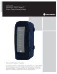
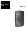
SBV5220 VoIP Cable Modem . . . . . . . . . . . . . . . . . . . . . . . . . . . . . . . . . . . . . . . . . . . . . . . . . . . . . . . . . . . . . . . . . . .1
SBV5220 VoIP Telephone Service . . . . . . . . . . . . . . . . . . . . . . . . . . . . . . . . . . . . . . . . . . . . . . . . . . . . . . . . . . . . . . .1
Telephone Features Supported by the SBV5220 . . . . . . . . . . . . . . . . . . . . . . . . . . . . . . . . . . . . . . . . . . . . . . . . . . .2
Top and Front Panel . . . . . . . . . . . . . . . . . . . . . . . . . . . . . . . . . . . . . . . . . . . . . . . . . . . . . . . . . . . . . . . . . . . . . . . . . . .3
Rear Panel . . . . . . . . . . . . . . . . . . . . . . . . . . . . . . . . . . . . . . . . . . . . . . . . . . . . . . . . . . . . . . . . . . . . . . . . . . . . . . . . . .4
Before You Begin. . . . . . . . . . . . . . . . . . . . . . . . . . . . . . . . . . . . . . . . . . . . . . . . . . . . . . . . . . . . 5
Precautions . . . . . . . . . . . . . . . . . . . . . . . . . . . . . . . . . . . . . . . . . . . . . . . . . . . . . . . . . . . . . . . . . . . . . . . . . . . . . . . . .6
Signing Up for Service . . . . . . . . . . . . . . . . . . . . . . . . . . . . . . . . . . . . . . . . . . . . . . . . . . . . . . . . . . . . . . . . . . . . . . . . .7
Computer System Requirements . . . . . . . . . . . . . . . . . . . . . . . . . . . . . . . . . . . . . . . . . . . . . . . 8
Ethernet Card . . . . . . . . . . . . . . . . . . . . . . . . . . . . . . . . . . . . . . . . . . . . . . . . . . . . . . . . . . . . . . . . . . . . . . . . . . . . . . . .8
USB Connection . . . . . . . . . . . . . . . . . . . . . . . . . . . . . . . . . . . . . . . . . . . . . . . . . . . . . . . . . . . . . . . . . . . . . . . . . . . . . .8
Battery Installation . . . . . . . . . . . . . . . . . . . . . . . . . . . . . . . . . . . . . . . . . . . . . . . . . . . . . . . . . . 9
Installation and Configuration . . . . . . . . . . . . . . . . . . . . . . . . . . . . . . . . . . . . . . . . . . . . . . . . 10
Cabling and Startup for a Single User . . . . . . . . . . . . . . . . . . . . . . . . . . . . . . . . . . . . . . . . . . . . . . . . . . . . . . . . . . . .10
Setting Up a USB Driver . . . . . . . . . . . . . . . . . . . . . . . . . . . . . . . . . . . . . . . . . . . . . . . . . . . . . . . . . . . . . . . . . . . . . . .12
Setting Up a USB Driver in Windows 98 Second Edition . . . . . . . . . . . . . . . . . . . . . . . . . . . . . . . . . . . . . . . . . . . .13
Setting Up a USB Driver in Windows 2000 . . . . . . . . . . . . . . . . . . . . . . . . . . . . . . . . . . . . . . . . . . . . . . . . . . . . . .17
Setting Up a USB Driver in Windows Me . . . . . . . . . . . . . . . . . . . . . . . . . . . . . . . . . . . . . . . . . . . . . . . . . . . . . . . .20
Setting Up a USB Driver in Windows XP . . . . . . . . . . . . . . . . . . . . . . . . . . . . . . . . . . . . . . . . . . . . . . . . . . . . . . . .21
Configuring TCP/IP . . . . . . . . . . . . . . . . . . . . . . . . . . . . . . . . . . . . . . . . . . . . . . . . . . . . . . . . . . . . . . . . . . . . . . . . . .22
Configuring TCP/IP in Windows 98, Windows 98 Second Edition, or Windows Me . . . . . . . . . . . . . . . . . . . . . . . .22
Configuring TCP/IP in Windows 2000 . . . . . . . . . . . . . . . . . . . . . . . . . . . . . . . . . . . . . . . . . . . . . . . . . . . . . . . . . .25
Configuring TCP/IP in Windows XP . . . . . . . . . . . . . . . . . . . . . . . . . . . . . . . . . . . . . . . . . . . . . . . . . . . . . . . . . . . .28
Verifying the IP Address . . . . . . . . . . . . . . . . . . . . . . . . . . . . . . . . . . . . . . . . . . . . . . . . . . . . . . . . . . . . . . . . . . . . . . .32
Verifying the IP Address in Windows 98, Windows 98 Second Edition, or Windows Me . . . . . . . . . . . . . . . . . . . .32
Verifying the IP Address in Windows 2000 or Windows XP . . . . . . . . . . . . . . . . . . . . . . . . . . . . . . . . . . . . . . . . . .33
Renewing Your IP Address . . . . . . . . . . . . . . . . . . . . . . . . . . . . . . . . . . . . . . . . . . . . . . . . . . . . . . . . . . . . . . . . . . . .34
Cabling for Multiple Users . . . . . . . . . . . . . . . . . . . . . . . . . . . . . . . . . . . . . . . . . . . . . . . . . . . 35
Ethernet and USB . . . . . . . . . . . . . . . . . . . . . . . . . . . . . . . . . . . . . . . . . . . . . . . . . . . . . . . . . . . . . . . . . . . . . . . . . . .35
Ethernet . . . . . . . . . . . . . . . . . . . . . . . . . . . . . . . . . . . . . . . . . . . . . . . . . . . . . . . . . . . . . . . . . . . . . . . . . . . . . . . . . . .36
Wall Mounting the SBV5220 . . . . . . . . . . . . . . . . . . . . . . . . . . . . . . . . . . . . . . . . . . . . . . . . . . 37
Wall Mounting Template . . . . . . . . . . . . . . . . . . . . . . . . . . . . . . . . . . . . . . . . . . . . . . . . . . . . . . . . . . . . . . . . . . . . . . .39
Troubleshooting . . . . . . . . . . . . . . . . . . . . . . . . . . . . . . . . . . . . . . . . . . . . . . . . . . . . . . . . . . . 40
Front-Panel Lights and Error Conditions . . . . . . . . . . . . . . . . . . . . . . . . . . . . . . . . . . . . . . . . . . . . . . . . . . . . . . . . . .41
SBV5220 VoIP Cable Modem User Guide
viii
Introduction
Installation
Troubleshooting
Glossary
License
Removing the USB Driver from Windows 98 Second Edition or Windows Me . . . . . . . . . . . . . . . . . . . . . . . . . . . . .42
Removing the USB Driver from Windows 2000 . . . . . . . . . . . . . . . . . . . . . . . . . . . . . . . . . . . . . . . . . . . . . . . . . . . . .43
Removing the USB Driver from Windows XP . . . . . . . . . . . . . . . . . . . . . . . . . . . . . . . . . . . . . . . . . . . . . . . . . . . . . . .45
Running the Motorola USB Driver Removal Utility . . . . . . . . . . . . . . . . . . . . . . . . . . . . . . . . . . . . . . . . . . . . . . . . . . .48
Contact Us . . . . . . . . . . . . . . . . . . . . . . . . . . . . . . . . . . . . . . . . . . . . . . . . . . . . . . . . . . . . . . . . 50
Frequently Asked Questions . . . . . . . . . . . . . . . . . . . . . . . . . . . . . . . . . . . . . . . . . . . . . . . . . 50
Glossary . . . . . . . . . . . . . . . . . . . . . . . . . . . . . . . . . . . . . . . . . . . . . . . . . . . . . . . . . . . . . . . . . . 52
Software License . . . . . . . . . . . . . . . . . . . . . . . . . . . . . . . . . . . . . . . . . . . . . . . . . . . . . . . . . . . 54
SBV5220 VoIP Cable Modem User Guide
ix
Introduction
Installation
Troubleshooting
Glossary
License
Introduction
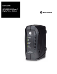
Congratulations on your new Motorola SBV5220 Voice over Internet Protocol (VoIP) cable modem! It provides
high-speed access to the Internet and other online services, and connections for up to two telephone lines.
SBV5220 VoIP Cable Modem
Your SBV5220 VoIP cable modem transmits and receives data much faster than traditional dial-up or DSL (digital
subscriber line) modems. It lets you enjoy surfing the Web without the long wait. Because many network and other
factors can affect performance, the actual speed will vary.
Unlike a dial-up modem, your SBV5220 VoIP cable modem is always online. Just open your browser and surf!
You can use your high-speed, upgradeable VoIP cable modem to connect one or more computers in your home or
business to the Internet. You can connect:
•
A single computer equipped with a Universal Serial Bus (USB) port directly to the USB port on the SBV5220
VoIP cable modem
•
A single computer equipped with an Ethernet adapter directly to the Ethernet port on the SBV5220 VoIP cable
modem
•
Two computers, one to the USB port and one to the Ethernet port
•
Up to 31 computers to a single SBV5220 VoIP cable modem using an Ethernet hub, as shown in “Cabling for
Multiple Users” on page 35
For easiest set-up, use the Installation Assistant on the SBV5220 VoIP Cable Modem CD-ROM.
SBV5220 VoIP Telephone Service
The SBV5220 also provides telephone service through your cable connection with the same features as your
traditional phone service, including standby power with an integrated battery backup in the event that you lose AC
power. You can connect up to two standard telephone lines using your SBV5220 VoIP cable modem, supporting:
•
Local and long-distance calling
•
Standby power support for a minimum of six hours standby or four hours talk time
•
Standard telephone feature support. For a full listing, see “Telephone Features Supported by the SBV5220”
on page 2.
•
Telephone modem and fax support
•
HTML diagnostic page
•
Software upgrades over the network to provide new or improved services
Caution
Use only a standard telephone. Digital phones used in many businesses that connect to a PBX
(private branch exchange) do not operate with the SBV5220.
SBV5220 VoIP Cable Modem User Guide
1
Introduction
Installation
Troubleshooting
Glossary
License
Telephone Features Supported by the SBV5220
The SBV5220 supports the telephone features listed below. Some features listed may not be available on your
telephone. Feature availability may also be determined by your telephone service provider.
•
Standard two-wire telephone connection for voice, fax, and telephone modem operation. The connection to
the telephone equipment is made with a standard RJ-11 jack and plug.
•
Re-dial number
•
Speed dial
•
Call forwarding
•
Call hold and mute
•
Call return
•
Call waiting
•
Caller ID
•
Caller ID block
•
Three-way calling
•
Voice mail
•
Telephony Devices for the Disabled (TDD)
•
On hook, off hook detection
•
Operator barge-in
•
Standard call progress signals
•
Dial-tone stutter
•
Dial-tone busy
•
Fast-busy stutter dial-tone call waiting
•
No support for pulse-dial equipment
SBV5220 VoIP Cable Modem User Guide
2
Introduction
Installation
Troubleshooting
Glossary
License
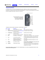
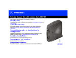
Top and Front Panel
For added security, you can press the Standby button (1) to suspend your Internet connection. No data is
transmitted or received from the Internet when the Standby light is on. All other front-panel lights turn off until you
press the Standby button again, except for Tel 1 and Tel 2.
The model number on your VoIP
cable modem may be different
than in the illustrations and
screen images in this guide.
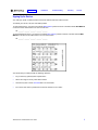
The lights provide information about power, communications, and errors:
Key Light
Flashing
On
2
Power
Startup diagnostics in progress.
VoIP cable modem powered on.
3
DS (downstream) Scanning for a receive (downstream) Downstream channel connected.
channel connection.
4
US (upstream)
Scanning for a send (upstream)
channel connection.
Upstream channel connected.
5
Online
Scanning for a network connection.
Startup process completed.
6
Link
Transmitting or receiving data.
A device, such as a computer or hub, is connected to
the USB or Ethernet connectors on the back panel.
7
Tel 1
Connected and activated,
telephone is off-hook (in use).
Connected and activated, the telephone is on-hook
(not in use).
8
Tel 2
Connected and activated,
telephone is off-hook (in use).
Connected and activated, the telephone is on-hook
(not in use).
9
Battery
AC power not present.
Normal condition indicating that AC power present and
the battery is in good condition.
10
Standby
This light does not flash.
Internet service blocked because the Standby button
was pressed. If this light is on, all other lights are off,
except for Tel 1 and Tel 2.
During normal operation, the Power, DS, US, and Online lights are on and the Link light flashes when the VoIP
cable modem is transferring data.
SBV5220 VoIP Cable Modem User Guide
3
Introduction
Installation
Troubleshooting
Glossary
License
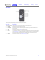
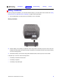
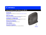
Rear Panel
The rear panel provides cabling connectors and the power receptacle:
Key Item
Description
1 & 2 Tel 1 and Tel 2 Telephone ports 1 and 2 provide connections for two telephone lines.
3
POWER
Provides AC power to the VoIP cable modem.
4
ETHERNET
Provides the connection to Ethernet equipped computers using a cable terminated with an
RJ-45 connector.
5
USB
Provides the connection to USB equipped computers.
6
Reset
If you experience a problem, you can push this recessed button to reset the VoIP cable modem
(see “Troubleshooting” on page 40). Resetting may take some time (5 to 30 minutes) because
the VoIP cable modem must find and lock on the appropriate communications channels.
7
CABLE
Provides the connection to the coaxial cable (coax) outlet.
SBV5220 VoIP Cable Modem User Guide
4
Introduction
Installation
Troubleshooting
Glossary
License
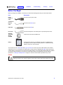
Before You Begin
Before you begin the installation, check that you received the following items with your VoIP cable modem:
Item
Description
Power
adapter or
cable
Connects to the AC power outlet
10/100Base-T
Ethernet
cable
Connects to the Ethernet port
USB cable
Connects to the USB port
Phone wire
Connects the telephone to the cable system to provide telephone service
SBV5220
VoIP Cable
Modem
CD-ROM
Contains the User Guide and USB drivers
Battery
Provides standby power for your SBV5220 (one each). The SBV5220 has
the capability to accommodate two standby batteries. For additional standby
batteries, contact your service provider.
You will need 75-ohm coaxial cable with F-type connectors to connect your VoIP cable modem to the nearest
cable outlet. If a TV is connected to the cable outlet, you may need a 5–900 MHz RF splitter and a total of three
coaxial cables to connect both the TV and the VoIP cable modem. The coaxial cable and RF splitter are available
at consumer electronics stores. To connect your VoIP cable modem to an Ethernet hub, see the network
description in “Cabling for Multiple Users” on page 35. Check the documentation provided with your hub.
Caution
This product is for indoor use only. Do not route the USB, Ethernet, or telephone cables outside of the
building. Exposure of the cables to lightning could create a safety hazard and damage the product.
SBV5220 VoIP Cable Modem User Guide
5
Introduction
Installation
Troubleshooting
Glossary
License
Precautions
Postpone VoIP cable modem installation until there is no risk of thunderstorm or lightning activity in the area.
To avoid damaging the VoIP cable modem with static electricity:
•
Always first connect the coaxial cable to the grounded cable TV wall outlet.
•
Before you connect or disconnect the USB or Ethernet cable from your VoIP cable modem or PC, always
touch the coaxial cable connector on the VoIP cable modem to release any static charges.
To avoid damaging your VoIP cable modem or PC with static electricity:
Before you connect or
disconnect the USB or
Ethernet cable, touch the
coaxial cable connector on
the VoIP cable modem.
Always make the wall
connection first.
To prevent overheating the VoIP cable modem, do not block the ventilation holes.
Do not open the VoIP cable modem. Refer all service to your cable provider.
Wipe the VoIP cable modem with a clean, dry cloth. Never use cleaning fluid or similar chemicals. Do not spray
cleaners directly on the unit or use forced air to remove dust.
Caution
Contact your cable provider before connecting your VoIP cable modem to your existing telephone wiring.
Do not connect the telephone wire to a traditional telephone (PSTN) service.
SBV5220 VoIP Cable Modem User Guide
6
Introduction
Installation
Troubleshooting
Glossary
License
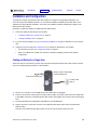
Signing Up for Service
You must sign up with a cable provider to access the Internet and other online services.
To activate your service, call your local cable provider.
To receive data service, you need to provide the MAC address printed on the bar code label marked HFC MAC ID
on the back of the cable modem. You can record it here:
00 : ______ : ______ : ______ : ______ : ______
To receive telephone service, you need to provide the MAC address printed on the bar code label marked MTA
MAC ID on the back of the cable modem. You can record it here:
00 : ______ : ______ : ______ : ______ : ______
You should ask your cable provider the following questions:
•
Do you have any special system requirements?
•
When can I begin to use my VoIP cable modem?
•
Are there any files I need to download after I am connected?
•
Do I need a user name or password to access the Internet or use e-mail?
SBV5220 VoIP Cable Modem User Guide
7
Introduction
Installation
Troubleshooting
Glossary
License
Computer System Requirements
You can use any Web browser, such as Microsoft® Internet Explorer or Netscape Navigator®, with your SBV5220
VoIP cable modem.
For Microsoft Windows computers, the Installation Assistant application automatically checks your system
configuration. You can start the Installation Assistant from the Main Menu on the SBV5220 VoIP Cable Modem
CD-ROM.
Your SBV5220 VoIP cable modem is compatible with Microsoft Windows®, Macintosh®, UNIX®, and Linux®
computers. Windows® 95 is not supported by the SBV5220.
You must have the latest version of your operating system installed with all current service packs and patches.
Ethernet Card
You can use the Ethernet connection with any Windows, Macintosh, UNIX, or Linux computer equipped with a
10Base-T or 10/100Base-T Ethernet card.
The original version of Windows® 98, Windows® NT, UNIX, Linux, or Macintosh computers must use the Ethernet
connection.
If you use an Ethernet card, it must be installed in your computer before you install your SBV5220 VoIP cable
modem. If it is not installed, follow the installation instructions provided with your Ethernet card.
USB Connection
You can use the USB connection with any PC running Windows® 98 Second Edition, Windows® 2000, Windows
Me®, or Windows XP™ that has a USB interface. The USB connection requires special USB driver software that is
supplied on the SBV5220 VoIP Cable Modem CD-ROM.
You can upgrade your USB drivers from our Downloads page http://broadband.motorola.com/noflash/
usb_drivers.asp.
SBV5220 VoIP Cable Modem User Guide
8
Introduction
Installation
Troubleshooting
Glossary
License
Battery Installation
Before you begin the installation, you must first install the battery in your VoIP cable modem. Please read “Safety
Requirements for the SBV5220 Lithium-Ion Battery” on page iv before proceeding.
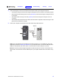
1
Place the SBV5220 on its side and remove the battery cover on the bottom.
Battery Installation
2
Slide the battery into the battery compartment until it is fully seated. The battery is keyed so that it cannot be
installed incorrectly. Make sure that the pull-tab on the battery is accessible and does not prevent the battery
cover from closing properly.
3
Re-install the battery cover with the locking tabs seated downward, and then push the cover forward.
It may take up to 12 hours to reach full charge when:
•
The battery is installed for the first time.
•
The battery is replaced.
•
The battery is fully discharged.
SBV5220 VoIP Cable Modem User Guide
9
Introduction
Installation
Troubleshooting
Glossary
License
Installation and Configuration
To install and configure your Motorola VoIP cable modem for a single PC running Microsoft Windows, we
recommend using the Installation Assistant. You can start the Installation Assistant from the Main Menu on the
SBV5220 VoIP Cable Modem CD-ROM. In most cases, the Installation Assistant automatically configures your
Motorola VoIP cable modem.
Otherwise, to install and configure your Motorola VoIP cable modem:
1
Connect the cables as described for your situation:
•
“Cabling and Startup for a Single User” on page 10
•
“Cabling for Multiple Users” on page 35
2
If you are using the USB port only, go to “Setting Up a USB Driver” on page 12. Ethernet users can skip this
step.
3
Configure TCP/IP and verify the IP address for your computer as described for your situation:
•
•
For Windows computers, see “Configuring TCP/IP” on page 22.
Refer to your Macintosh or UNIX user manual for information regarding TCP/IP and IP address
configuration.
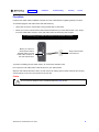
Cabling and Startup for a Single User
Allow some time (5 to 30 minutes) to power up the first time because the Motorola VoIP cable modem must find
and lock on the appropriate channels for communications.
Always connect coaxial cable
to the wall outlet first.
To electrical outlet (step 4)
To cable outlet
(step 2)
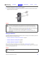
1
Be sure your computer is on and the Motorola VoIP cable modem is unplugged.
2
Connect one end of the coaxial cable to the cable outlet or splitter. Connect the other end of the coaxial cable
to the CABLE connector on the Motorola VoIP cable modem. Hand-tighten the connectors to avoid damaging
them.
3
Insert the SBV5220 VoIP Cable Modem CD-ROM into your CD-ROM drive.
4
Plug the AC power cord into the connector on the Motorola VoIP cable modem and an unswitched AC
electrical outlet.
This turns on the Motorola VoIP cable modem. You do not need to unplug it when not in use.
SBV5220 VoIP Cable Modem User Guide
10
Introduction
5
6
Installation
Troubleshooting
Glossary
License
Check that the lights on the front of the Motorola VoIP cable modem cycle through this sequence:
•
•
Power flashes during the self-test and changes to solid green when the self-test is successfully complete.
•
Send flashes while scanning for the send (upstream) channel and changes to solid green when it is
connected.
•
Online flashes while the Motorola VoIP cable modem downloads configuration data and changes to solid
green when the download is complete.
Receive flashes while scanning for the receive (downstream) channel and changes to solid green when it
is connected.
Connect your computer to the Motorola VoIP cable modem using USB or Ethernet:
Either/or
Motorola VoIP cable
Computer
USB: Be sure the SBV5220 VoIP Cable Modem CD-ROM is inserted in your CD-ROM drive. Perform the
appropriate procedure for Setting Up a USB Driver for your Windows version. Connect the USB cable to the
USB port on the Motorola VoIP cable modem. Connect the other end to the USB port on your PC.
Ethernet: Connect the provided straight-through Ethernet cable to the Ethernet connector on the Motorola VoIP
cable modem. Connect the other end to the Ethernet port on your computer. Ethernet users do not need to set up
USB.
SBV5220 VoIP Cable Modem User Guide
11
Introduction
Installation
Troubleshooting
Glossary
License
7
Perform the procedures for “Configuring TCP/IP” on page 22.
8
To connect the telephone line, plug a phone wire into the Tel 1 connector. You can also connect a second
telephone line to the Tel 2 connector.
Either/or
Caution!
To reduce the risk of fire, use only No. 26 or larger UL Listed or CSA Certified Telecommunication
Line Cord or national equivalent to connect a telephone line to your Motorola VoIP cable modem.
Do not connect both the Ethernet and USB cables to the same computer. Connect to either Ethernet
or USB.
Contact your cable provider before connecting your Motorola VoIP cable modem to your existing telephone
wiring. Do not connect the telephone wire to a traditional telephone (PSTN) service.
Be sure the phone connectors are neither connected together nor connected to wall jacks on the
same network.
Setting Up a USB Driver
The following subsections describe setting up a USB driver. Before connecting a PC to the USB port, perform the
appropriate procedure for your Windows version:
•
“Setting Up a USB Driver in Windows 98 Second Edition” on page 13
•
“Setting Up a USB Driver in Windows 2000” on page 17
•
“Setting Up a USB Driver in Windows Me” on page 20
•
“Setting Up a USB Driver in Windows XP” on page 21
When you finish setting up the USB driver, you can continue with “Configuring TCP/IP” on page 22.
The Motorola VoIP cable modem USB driver does not support Macintosh or UNIX computers. For those systems,
you can connect through Ethernet only.
Caution!
Be sure the SBV5220 VoIP Cable Modem CD-ROM is inserted in the CD-ROM drive before you plug
in the USB cable.
SBV5220 VoIP Cable Modem User Guide
12
Introduction
Installation
Troubleshooting
Glossary
License
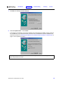
Setting Up a USB Driver in Windows 98 Second Edition
1
Insert the SBV5220 VoIP Cable Modem CD-ROM in the CD-ROM drive. This CD contains the USB drivers
and must be inserted and read by the PC before you connect the Motorola VoIP cable modem to the PC.
2
Connect the Motorola VoIP cable modem to your computer with a USB cable. For further instructions, see
“Cabling and Startup for a Single User” on page 10. A few seconds after you complete the USB connection,
the Add New Hardware Wizard window is displayed:
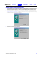
3
Click Next. The following window is displayed:
SBV5220 VoIP Cable Modem User Guide
13
Introduction
Installation
Troubleshooting
Glossary
License
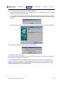
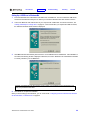
4
Be sure “Search for the best driver for your device” is selected and click Next. The following window is
displayed:
5
Be sure “CD-ROM drive” is the only box selected. Click Next.
The message “Please wait while Windows searches for a new driver for this device” is displayed.
If your computer successfully locates the driver, skip to step 8.
If your computer does not locate the driver, the previous window is displayed again.
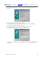
6
Select Specify a location and type the location of your CD-ROM drive.
To load the driver successfully, you may need to click Browse to manually select the NetMotCM.sys file from
the CD-ROM.
SBV5220 VoIP Cable Modem User Guide
14
Introduction
Installation
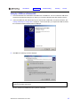
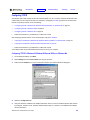
7
Click Next. The following window is displayed:
8
Select The updated driver... and click Next.
Troubleshooting
Glossary
License
If this window is not displayed, verify that the SBV5220 VoIP Cable Modem CD-ROM is properly inserted in
the CD-ROM drive. If you still cannot find the correct driver file, click Cancel to cancel the installation and
perform the procedure for “Removing the USB Driver from Windows 98 Second Edition or Windows Me” on
page 42. Then repeat this procedure.
Although your Motorola VoIP cable modem model number may be different than in the images in this
guide, the procedure is the same.
SBV5220 VoIP Cable Modem User Guide
15
Introduction
9
Installation
Troubleshooting
Glossary
License
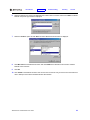
After the window shown under step 8 is displayed, click Next.
If a window with the message Copying Files... displays and asks for your CD-ROM drive, type your CD-ROM
drive letter (for example, “D:”) and click OK.
If an Insert Disk window similar to the following is displayed, Windows system files are needed to complete
the installation. To install the files, insert your Windows 98 Second Edition CD-ROM in the CD-ROM drive and
click OK.
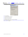
After all the necessary files are loaded, the following window is displayed confirming a successful installation:
10 Click Finish. The Systems Settings Change window is displayed:
11 Click Yes to restart your computer.
When you finish setting up the USB driver, you can continue with “Configuring TCP/IP in Windows 98, Windows
98 Second Edition, or Windows Me” on page 22.
If you have difficulties setting up the USB driver, perform “Removing the USB Driver from Windows 98 Second
Edition or Windows Me” on page 42 and repeat this procedure. If that does not correct your problem, see the
Regulatory, Safety, Software License, and Warranty Information card provided with your Motorola VoIP cable
modem for information about obtaining warranty service.
SBV5220 VoIP Cable Modem User Guide
16
Introduction
Installation
Troubleshooting
Glossary
License
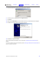
Setting Up a USB Driver in Windows 2000
1
Insert the SBV5220 VoIP Cable Modem CD-ROM in the CD-ROM drive. This CD contains the USB drivers
and must be inserted and read by the PC before you connect the Motorola VoIP cable modem to the PC.
2
Connect the Motorola VoIP cable modem to your computer with a USB cable. For further instructions, see
“Cabling and Startup for a Single User” on page 10. A few seconds after you complete the USB connection,
the Found New Hardware Wizard window is displayed:
3
Click Next. The following window is displayed:
Although your Motorola VoIP cable modem model number may be different than in the images in this
guide, the procedure is the same.
Be sure “Search for a suitable driver for my device” is selected.
SBV5220 VoIP Cable Modem User Guide
17
Introduction
4
Installation
Troubleshooting
Glossary
License
Click Next. The following window is displayed:
Be sure “CD-ROM drives” is the only box selected.
5
Click Next. The following window is displayed:
6
Click Next.
If the Insert Disk window is displayed, be sure the SBV5220 VoIP Cable Modem CD-ROM is in the CD-ROM
drive and follow steps 7 to 11. Otherwise, if the Completing the Found New Hardware window is displayed,
you can skip to step 12.
SBV5220 VoIP Cable Modem User Guide
18
Introduction
Installation
Troubleshooting
7
On the Insert Disk window, click OK. The Files Needed window is displayed:
8
If necessary, select your CD-ROM drive in the “Copy files from” list.
9
Click Browse.
Glossary
License
10 Double-click the NetMotCM.sys file in the CD-ROM root directory. The Files Needed window is displayed:
11 Click OK. The Found New Hardware Wizard window is displayed:
12 Click Finish to complete the installation.
When you finish setting up the USB driver, you can continue with “Configuring TCP/IP in Windows 2000” on
page 25.
If you have any difficulties setting up the USB driver, perform “Removing the USB Driver from Windows 2000” on
page 43 and repeat this procedure.
SBV5220 VoIP Cable Modem User Guide
19
Introduction
Installation
Troubleshooting
Glossary
License
Setting Up a USB Driver in Windows Me
1
Insert the SBV5220 VoIP Cable Modem CD-ROM in the CD-ROM drive. This CD contains the USB drivers
and must be inserted and read by the PC before you connect the Motorola VoIP cable modem to the PC.
2
Connect the Motorola VoIP cable modem to your computer with a USB cable. For further instructions, see
“Cabling and Startup for a Single User” on page 10. A few seconds after you complete the USB connection,
the Add New Hardware Wizard window is displayed:
3
Click Next. Windows automatically searches for the correct USB drivers and installs them. If the installation is
successful, the following window is displayed. Otherwise, be sure the SBV5220 VoIP Cable Modem CD-ROM
is correctly inserted in your CD-ROM drive.
Although your Motorola VoIP cable modem model number may be different than in the images in this
guide, the procedure is the same.
4
Click Finish to complete the installation.
When you finish setting up the USB driver, you can continue with “Configuring TCP/IP in Windows 98, Windows
98 Second Edition, or Windows Me” on page 22.
SBV5220 VoIP Cable Modem User Guide
20
Introduction
Installation
Troubleshooting
Glossary
License
Setting Up a USB Driver in Windows XP
1
Insert the SBV5220 VoIP Cable Modem CD-ROM in the CD-ROM drive. This CD contains the USB drivers
and must be inserted and read by the PC before you connect the Motorola VoIP cable modem to the PC.
2
Connect the Motorola VoIP cable modem to your computer with a USB cable. For further instructions, see
“Cabling and Startup for a Single User” on page 10. A few seconds after you complete the USB connection,
the Found New Hardware Wizard window is displayed:
3
Be sure “Install the software automatically” is selected.
4
Click Next. Windows automatically searches for the correct USB drivers and installs them. If the installation is
successful, the following window is displayed:
Although your Motorola VoIP cable modem model number may be different than in the images in
this guide, the procedure is the same.
5
Click Finish to complete the installation. Otherwise, be sure the SBV5220 VoIP Cable Modem CD-ROM is
correctly inserted in your CD-ROM drive.
When you finish setting up the USB driver, you can continue with “Configuring TCP/IP in Windows XP” on
page 28.
SBV5220 VoIP Cable Modem User Guide
21
Introduction
Installation
Troubleshooting
Glossary
License
Configuring TCP/IP
The Motorola VoIP cable modem contains all required software. You do not need to configure the Motorola VoIP
cable modem, but you must be sure that your computer is configured for TCP/IP (a protocol for communication
between computers). Perform one of the following:
•
“Configuring TCP/IP in Windows 98, Windows 98 Second Edition, or Windows Me” on page 22
•
“Configuring TCP/IP in Windows 2000” on page 25
•
“Configuring TCP/IP in Windows XP” on page 28
•
Follow the instructions in your Macintosh or UNIX user manual
After configuring TCP/IP, perform one of the following to verify the IP address:
•
“Verifying the IP Address in Windows 98, Windows 98 Second Edition, or Windows Me” on page 32
•
“Verifying the IP Address in Windows 2000 or Windows XP” on page 33
•
Follow the instructions in your Macintosh or UNIX user manual
Your cable provider may provide additional instructions to set up your computer.
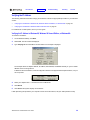
Configuring TCP/IP in Windows 98, Windows 98 Second Edition, or Windows Me
1
On the Windows Desktop, click Start.
2
Select Settings and then Control Panel from the pop-up menus.
3
Double-click the Network icon on the Control Panel window. The Network window is displayed:
4
Select the Configuration tab.
5
Verify that TCP/IP is installed for the adapter that will be used to connect to the Motorola VoIP cable modem
by looking for TCP/IP. If found, TCP/IP is installed. Skip to step 10. If TCP/IP is not installed for the adapter,
continue with step 6.
SBV5220 VoIP Cable Modem User Guide
22
Introduction
Installation
Troubleshooting
Glossary
License
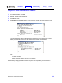
6
Select the adapter to be used for the SBV5220 VoIP cable modem connection and then click Add. The Select
Network Component Type window is displayed:
7
Select the Protocol option and click Add. The Select Network Protocol window is displayed:
8
Click Microsoft in the Manufacturers section and click TCP/IP in the Network Protocol section of Select
Network Protocol window.
9
Click OK.
10 Click TCP/IP on the Network window. If there is more than one TCP/IP entry, choose the one for the Ethernet
card or USB port connected to the Motorola VoIP cable modem.
SBV5220 VoIP Cable Modem User Guide
23
Introduction
Installation
Troubleshooting
Glossary
License
11 Click Properties. The TCP/IP Properties window is displayed:
12 Click the IP Address tab.
13 Click Obtain an IP address automatically.
14 Click OK to accept the TCP/IP settings.
15 Click OK to close the Network window.
16 Click OK when prompted to restart your computer and click OK again.
When you complete TCP/IP configuration, go to “Verifying the IP Address in Windows 98, Windows 98 Second
Edition, or Windows Me” on page 32.
SBV5220 VoIP Cable Modem User Guide
24
Introduction
Installation
Troubleshooting
Glossary
License
Configuring TCP/IP in Windows 2000
1
On the Windows Desktop, click Start.
2
Select Settings and then Control Panel from the pop-up menus. The Control Panel window is displayed:
In the steps that follow, a connection number such as 1, 2, or 3 is a reference displayed on PCs with multiple
network interfaces. PCs having only one network interface may display only the label Local Area Connection.
3
Double-click the Network and Dial-up Connections icon on the Control Panel window. The Network and
Dial-up Connections window is displayed:
4
Double-click Local Area Connection number. The value of number varies from system to system. The Local
Area Connection number Status window is displayed:
SBV5220 VoIP Cable Modem User Guide
25
Introduction
Installation
Troubleshooting
Glossary
License
5
Click Properties. The Local Area Connection Properties window is displayed:
6
If Internet Protocol (TCP/IP) is in the list of components, TCP/IP is installed. You can skip to step 10.
If Internet Protocol (TCP/IP) is not in the list, click Install. The Select Network Component Type window is
displayed:
7
Click Protocol on the Select Network Component Type window and click Add. The Select Network Protocol
window is displayed:
8
Click Internet Protocol (TCP/IP) in the Network Protocol section on the Select Network Protocol window.
SBV5220 VoIP Cable Modem User Guide
26
Introduction
9
Installation
Troubleshooting
Glossary
License
Click OK. The Local Area Connection number Properties window is re-displayed:
10 On the Local Area Connection number Properties window, be sure the box next to Internet Protocol
(TCP/IP) is selected.
11 Click Properties. The Internet Protocol (TCP/IP) Properties window is displayed:
12 Be sure Obtain IP address automatically and Obtain DNS server address automatically are selected.
Click OK to accept the TCP/IP settings.
13 Click OK to close the Local Area Connection number Properties window.
14 Click OK when prompted to restart your computer and click OK again.
When you complete the TCP/IP configuration, go to “Verifying the IP Address in Windows 2000 or Windows XP”
on page 33.
SBV5220 VoIP Cable Modem User Guide
27
Introduction
Installation
Troubleshooting
Glossary
License
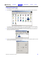
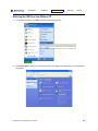
Configuring TCP/IP in Windows XP
1
On the Windows desktop, click Start to display the Start window shown.
2
Click Control Panel to display the Control Panel window. The display varies, depending on your Windows XP
view options. If the display is a Category view as shown below, continue with step 3. Otherwise, skip to
step 5.
SBV5220 VoIP Cable Modem User Guide
28
Introduction
Installation
Troubleshooting
Glossary
License
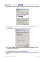
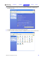
3
Click Network and Internet Connections. The Network and Internet Connections window is displayed:
4
On the Network and Internet Connections window, click Network Connections to display the LAN or
high-speed Internet connections. Skip to step 6.
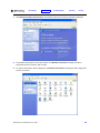
5
If a Classic view similar to below is displayed, click Network Connections to display the LAN or high-speed
Internet connections.
SBV5220 VoIP Cable Modem User Guide
29
Introduction
Installation
Troubleshooting
Glossary
License
6
Right-click your network connection. If more than one connection is displayed, be sure to select the one for
your network interface.
7
Select Properties from the pop-up menu. The Local Area Connection Properties window is displayed:
SBV5220 VoIP Cable Modem User Guide
30
Introduction
Installation
Troubleshooting
Glossary
License
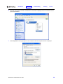
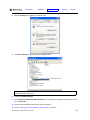
8
Select Internet Protocol (TCP/IP) and click Properties to display the Internet Protocol (TCP/IP) Properties
window:
9
On the Internet Protocol (TCP/IP) Properties window, verify that the settings are correct, as shown.
10 Click OK to close the TCP/IP Properties window.
11 Click OK to close the Local Area Connection Properties window.
When you complete the TCP/IP configuration, go to “Verifying the IP Address in Windows 2000 or Windows XP”
on page 33.
SBV5220 VoIP Cable Modem User Guide
31
Introduction
Installation
Troubleshooting
Glossary
License
Verifying the IP Address
The following subsections describe verifying an IP address. Perform the appropriate procedure for your Windows
version:
•
“Verifying the IP Address in Windows 98, Windows 98 Second Edition, or Windows Me” on page 32
•
“Verifying the IP Address in Windows 2000 or Windows XP” on page 33
For a Macintosh or UNIX system, refer to your user guide.
Verifying the IP Address in Windows 98, Windows 98 Second Edition, or Windows Me
To check the IP address:
1
On the Windows Desktop, click Start.
2
Select Run. The Run window is displayed.
3
Type winipcfg.exe and click OK. A window similar to the example is displayed:
The example values for Adapter Address, IP Address, Subnet Mask, and Default Gateway on your PC will be
different than in the image above.
In Windows 98 Second Edition, if IP Autoconfiguration Address is displayed before Adapter Address, call your
service provider.
4
Select your adapter name — the Ethernet card or USB device.
5
Click Renew.
6
Click OK after the system displays an IP address.
If after performing this procedure your computer cannot access the Internet, call your cable provider for help.
SBV5220 VoIP Cable Modem User Guide
32
Introduction
Installation
Troubleshooting
Glossary
License
Verifying the IP Address in Windows 2000 or Windows XP
To check the IP address:
1
On the Windows Desktop, click Start.
2
Select Run. The Run window is displayed.
3
Type cmd and click OK.
4
Type ipconfig and press ENTER to display your IP configuration. A display, like below, indicates a normal
configuration:
If an Autoconfiguration IP Address is displayed as in the window below, there is an incorrect connection
between your PC and the Motorola VoIP cable modem or there are cable network problems.
Check:
•
Your cable connections
•
Whether you can see cable-TV channels on your television
After successfully verifying your cable connections and proper cable-TV operation, you can renew your IP
address.
SBV5220 VoIP Cable Modem User Guide
33
Introduction
Installation
Troubleshooting
Glossary
License
Renewing Your IP Address
To renew your IP address:
1
On the Windows Desktop, click Start.
2
Select Run. The Run window is displayed.
3
Type cmd and click OK.
4
Type ipconfig /renew and press ENTER. If a valid IP address is displayed as shown, Internet access should
be available.
5
Type exit and press ENTER to return to Windows.
If after performing this procedure your computer cannot access the Internet, call your cable provider for help.
SBV5220 VoIP Cable Modem User Guide
34
Introduction
Installation
Troubleshooting
Glossary
License
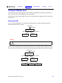
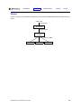
Cabling for Multiple Users
The Motorola VoIP cable modem supports several multiple-user configurations. Along with an optional hub or
router, it can serve as an Internet gateway for up to 31 computers.
Not all service providers support multiple-user service. For information about multiple-user service, contact your
cable provider.
Ethernet and USB
You can connect the USB port on one computer and the Ethernet port on another computer directly to the
Motorola VoIP cable modem, as shown.
Cable outlet
Coaxial cable
Motorola VoIP
cable modem
Ethernet cable
USB cable
Computer
Computer
Caution
Do not connect both the Ethernet and USB cables to the same computer.
You can connect a single computer to the USB port and from one to 31 remaining users to an Ethernet hub, as
shown. You cannot connect more than one computer to the Motorola VoIP cable modem through the USB port.
Cable outlet
Coaxial cable
Motorola VoIP
cable modem
USB cable
Computer
Ethernet cable
Ethernet hub
or switch
Ethernet cables
Computer
SBV5220 VoIP Cable Modem User Guide
Computer
Computer
35
Introduction
Installation
Troubleshooting
Glossary
License
Ethernet
You can connect up to 31 computers to an Ethernet hub connected to a SBV5220 Motorola VoIP cable modem, as
shown.
Cable outlet
Coaxial cable
Motorola VoIP
cable modem
Ethernet cable
Ethernet hub
or switch
Ethernet cable
Computer
SBV5220 VoIP Cable Modem User Guide
Computer
Computer
36
Introduction
Installation
Troubleshooting
Glossary
License
Wall Mounting the SBV5220
If you mount your SBV5220 on the wall, you must:
•
Locate the unit as specified by the local or national codes governing residential or business cable TV and
communications services.
•
Follow all local standards for installing a network interface unit/network interface device (NIU/NID).
If possible, mount the SBV5220 to concrete, masonry, a wooden stud, or other very solid wall material. Use
anchors if necessary, for example, if you must mount the unit on drywall.
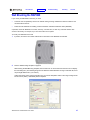
To mount your SBV5220 on the wall:
1
If present, remove the four rubber chassis feet on the bottom of the SBV5220 as indicated.
2
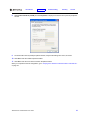
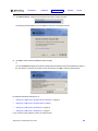
Print the Wall Mounting Template on page 39.
While viewing the Wall Mounting Template, click the Print icon or choose Print from the File menu to display
the Print dialog box. (The following image is from Adobe® Acrobat® Reader® running on Windows XP; there
may be slight differences in your version).
Under Print Range, select Current page. Be sure you print the template at 100% scale. Page scaling should
be set to None (100%). Click OK to print the template.
SBV5220 VoIP Cable Modem User Guide
37
Introduction
Installation
Troubleshooting
3
Measure the printed template with a ruler to ensure that it is the correct size.
4
Use a center punch to mark the center of the holes.
5
On the wall, locate the marks for the mounting holes.
Glossary
License
Caution
Before drilling holes, check the structure for potential damage to water, gas, or electric
lines.
6
See step 6 for recommended mounting hardware size. Drill holes to a depth and diameter appropriate for the
size and type of hardware you have selected.
7
If necessary, install an anchor in each hole.
Use M3.5 x 38 mm (#6 x 1 1/2 inch) screws with a flat underside and maximum screw head diameter of 9.0
mm (.35 inches) to mount the SBV5220.
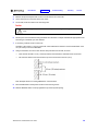
8
Using a screwdriver, turn each screw until the head protrudes from the wall, as shown:
—
There must be at least 2.5 mm (.10 inches) between the wall and the underside of the screw head.
— The maximum distance from the wall to the top of the screw head is 6.0 mm (.24 in)
Note: Example above for mounting SBV5220 on a wood surface.
9
Place the SBV5220 so the keyholes are above the mounting screws.
10 Slide the SBV5220 down so it stops against the top of the keyhole opening.
SBV5220 VoIP Cable Modem User Guide
38
Introduction
Installation
Troubleshooting
Glossary
License
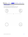
Wall Mounting Template
You can print this page to use as a wall mounting template.
Be sure you print it at 100% scale. Page scaling should be set to None (100%).
Measure the printed template with a ruler to ensure that it is the correct size
SBV5220 VoIP Cable Modem User Guide
39
Introduction
Installation
Troubleshooting
Glossary
License
Troubleshooting
If the solutions listed here do not solve your problem, contact your cable provider. Before calling your service
provider, try pressing the reset button on the rear panel or unplugging and plugging in the VoIP cable modem
power cord. Resetting the VoIP cable modem may take 5 to 30 minutes. Your service provider may ask for the
status of the front-panel lights as described in “Front-Panel Lights and Error Conditions” on page 41.
Problem
Possible Solutions
Green POWER light
is off
• Check that the power cord is properly plugged into the electrical outlet and the VoIP cable
modem.
• Check that the electrical outlet is working.
• If the Standby light is on, the Internet connection is off. Press the Standby button to
reconnect to the Internet.
No telephone
service
• Check the connection between the SBV5220 and your telephone.
• If your telephone requires external power, check the AC power connection for your
telephone.
• Check the coaxial cable on the SBV5220 and the electrical outlet. Hand-tighten the cable
connectors if necessary.
• Check the lights on the front panel. Make sure the green power light is on. If it is not, check
that the power cord is properly plugged into the electrical outlet and the VoIP cable modem.
• If you have cable TV, check that your TV is working and the picture is clear. If you cannot
receive your regular TV channels, your telephone service will not function.
Cannot send or
receive data
• Check the lights on the front panel. Note the first light from top to bottom that is off. This light
indicates where the error occurred, as described in “Front-Panel Lights and Error
Conditions” on page 41.
• If all lights are off except the Standby and Tel 1/Tel 2 lights, the VoIP cable modem is in
Standby mode. Press the Standby button to reconnect your Internet service. The Standby
button does not affect the Tel 1/Tel 2 LEDs.
• If you have cable TV, check that your TV is working and the picture is clear. If you cannot
receive your regular TV channels, your data service will not function.
• Check the coaxial cable on the SBV5220 and the electrical outlet. Hand-tighten the cable
connectors if necessary.
• Check the IP address. Follow the steps in “Verifying the IP Address in Windows 98,
Windows 98 Second Edition, or Windows Me” on page 32 or “Verifying the IP Address in
Windows 2000 or Windows XP” on page 33. Call your cable provider if you need an IP
address.
• Check that the USB or Ethernet cable is properly connected to the VoIP cable modem and
your computer.
Problems related to
unsuccessful USB
driver installation
Remove the USB driver. Follow the instructions in one of:
• “Removing the USB Driver from Windows 98 Second Edition or Windows Me” on page 42
• “Removing the USB Driver from Windows 2000” on page 43
• “Removing the USB Driver from Windows XP” on page 45
Then perform “Running the Motorola USB Driver Removal Utility” on page 48.
SBV5220 VoIP Cable Modem User Guide
40
Introduction
Installation
Troubleshooting
Glossary
License
Front-Panel Lights and Error Conditions
Light
Turns Off During Startup If
Turns Off During Normal Operation If
Power
The VoIP cable modem is not properly plugged
into the power outlet
The VoIP cable modem is unplugged or is in standby
mode. Plug it in or press the Standby button.
Battery
AC power is not present.
AC power is not present.
DS
(Receive)
The receive channel cannot be acquired
The receive channel is lost
US
(Send)
The send channel cannot be acquired
The send channel is lost
Online
IP registration is unsuccessful
The IP registration is lost
Tel 1 or
Tel 2
If the Tel light fails to flash during startup,
telephone line configuration has failed.
Connected during a phone call and does not blink,
telephone connection is lost.
If a telephone line is properly connected and the Tel 1 or Tel 2 light remains off, the line has not been set up for
service. Contact your service provider.
For more information about the lights, see “Top and Front Panel” on page 3.
SBV5220 VoIP Cable Modem User Guide
41
Introduction
Installation
Troubleshooting
Glossary
License
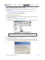
Removing the USB Driver from Windows 98 Second Edition or Windows Me
1
On the Windows Desktop, right-click one of:
•
In Windows 98 Second Edition, the Network Neighborhood icon
•
In Windows Me, the My Network Places icon
The Network window is displayed:
Although your Motorola VoIP cable modem model number may be different than in the images in this
guide, the procedure is the same.
2
Click the Motorola SURFboard USB Cable Modem and click Remove. The Network window no longer
displays Motorola SURFboard USB Cable Modem in the list:
SBV5220 VoIP Cable Modem User Guide
42
Introduction
Installation
Troubleshooting
3
Click OK. The System Settings Change window is displayed:
4
Disconnect the USB cable from your computer or VoIP cable modem.
5
Click Yes to restart your computer.
6
Perform “Running the Motorola USB Driver Removal Utility” on page 48.
Glossary
License
Removing the USB Driver from Windows 2000
1
On your Windows desktop, click Start.
2
Click Settings.
3
Double-click Control Panel to display the Control Panel window:
4
Double-click System to display the System Properties window.
SBV5220 VoIP Cable Modem User Guide
43
Introduction
Installation
Troubleshooting
5
Click the Hardware tab:
6
Click Device Manager to display the Device Manager window:
Glossary
License
Although your Motorola VoIP cable modem model number may be different than in the images in this
guide, the procedure is the same.
7
Double-click Network Adapters.
8
Click the Motorola SURFboard USB Cable Modem. The Uninstall icon is displayed on the window near the
top.
9
Click Uninstall. A window is displayed.
10 Click OK.
11 Close the Device Manager and Control Panel windows.
12 Perform “Running the Motorola USB Driver Removal Utility” on page 48.
SBV5220 VoIP Cable Modem User Guide
44
Introduction
Installation
Troubleshooting
Glossary
License
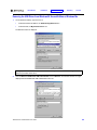
Removing the USB Driver from Windows XP
1
On the Windows desktop, click Start to display the Start window shown.
2
Click Control Panel to display the Control Panel window. The display varies, depending on your Windows XP
view options.
SBV5220 VoIP Cable Modem User Guide
45
Introduction
Installation
Troubleshooting
Glossary
License
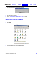
3
If a Category view similar to the image under step 2 is displayed, click Performance and Maintenance.
Otherwise, skip to step 5.
4
Click System to display the System Properties window. Skip to step 6.
5
If a Classic view similar to the following is displayed, click System to display the System Properties window:
SBV5220 VoIP Cable Modem User Guide
46
Introduction
Installation
Troubleshooting
6
Click the Hardware tab to display the Hardware page:
7
Click Device Manager to display the Device Manager window:
Glossary
License
Although your Motorola VoIP cable modem model number may be different than in the images in this
guide, the procedure is the same.
8
Double-click Network adapters.
9
Click the Motorola SURFboard USB Cable Modem. The Uninstall icon is displayed on the window near the
top. Click Uninstall.
10 Close the Device Manager window and Control Panel windows.
11 Perform “Running the Motorola USB Driver Removal Utility” on page 48.
SBV5220 VoIP Cable Modem User Guide
47
Introduction
Installation
Troubleshooting
Glossary
License
Running the Motorola USB Driver Removal Utility
Before running the Motorola USB Driver Removal Utility, you must run the Windows Device Manager by
performing one of:
•
•
•
“Removing the USB Driver from Windows 98 Second Edition or Windows Me” on page 42
“Removing the USB Driver from Windows 2000” on page 43
“Removing the USB Driver from Windows XP” on page 45
To run the Motorola USB Driver Removal Utility:
1
Insert the SBV5220 VoIP Cable Modem CD-ROM in the CD-ROM drive. After a short time, a window with
language choices is displayed.
2
Press the Esc key on the keyboard to exit the start-up screens.
3
To start Windows Explorer, click Start and select Run. On the Run window, type explorer and click OK.
Your Windows Explorer may appear different than in the image on this page. There are
variations between Windows versions and you can configure Windows Explorer as you like.
4
Double-click My Computer.
5
Double-click the Motorola CD icon (D: in the image).
6
Double-click remove or remove.exe to run the Remove utility from the SBV5220 VoIP Cable Modem
CD-ROM. The Motorola USB Driver Removal window is displayed. Be sure the USB cable is disconnected.
SBV5220 VoIP Cable Modem User Guide
48
Introduction
7
Installation
Troubleshooting
Glossary
License
Click Remove Driver. A progress bar indicates that the driver is being removed.
The following window displays when the USB driver has been successfully removed:
8
Click Exit to exit the Motorola USB Driver Removal Utility.
or
You can click Details to display informational messages about the files that were found and deleted, similar to
the ones shown. If necessary, scroll down to view the entire list. Click OK to close the details window:
Re-install the USB driver following one of:
•
“Setting Up a USB Driver in Windows 98 Second Edition” on page 13
•
“Setting Up a USB Driver in Windows 2000” on page 17
•
“Setting Up a USB Driver in Windows Me” on page 20
•
“Setting Up a USB Driver in Windows XP” on page 21
If you continue to have problems, contact your cable provider.
SBV5220 VoIP Cable Modem User Guide
49
Introduction
Installation
Troubleshooting
Glossary
License
Contact Us
If you need assistance while working with the Motorola VoIP cable modem, contact your cable provider. For more
information about customer service, technical support, or warranty claims, see the Regulatory, Safety, Software
License, and Warranty Information card provided with the Motorola VoIP cable modem.
For answers to typical questions, see “Frequently Asked Questions” on page 50.
For information about Motorola consumer cable products, education, and support, visit
www.broadbandmotorola.com/consumers.
Frequently Asked Questions
Q
What is high-speed cable Internet access?
A
Cable Internet access uses cable television wires instead of telephone lines to connect to the Internet. It is
extremely fast and affordable and does not tie up telephone lines for incoming or outgoing calls and faxes.
Q
What is voice over Internet Protocol (VoIP)?
A
VoIP uses cable television wires instead of traditional telephone lines to provide voice and fax service.
Q
How fast is a VoIP cable modem?
A
A cable modem offers Internet access at speeds up to 100 times faster than a traditional phone modem. You
can experience speeds of over 1,000 Kbps. Network conditions such as traffic volume and the speed of the
sites you visit can affect download speeds.
Q
Can I still watch cable TV while using my VoIP cable modem?
A
Yes, your cable TV line can carry the TV signal while you send and receive information on the Internet.
Q
What are CableLabs® Certified, DOCSIS®, and Euro-DOCSIS?
A
CableLabs Certified, DOCSIS, and Euro-DOCSIS are the industry standards for high-speed data distribution
over cable television system networks. They are intended to ensure that all compliant VoIP cable modems
interface with all compliant cable systems. Your Motorola SBV5220 VoIP cable modem is DOCSIS-, or
Euro-DOCSIS certified.
Q
What is PacketCable?
A
PacketCable™ is an evolving set of interface specifications for delivering advanced, real-time multimedia
services over cable; for example, VoIP, multimedia conferencing, and interactive gaming.
Q
If I have a VoIP cable modem, can I still use my old 28.8 Kbps or 56 Kbps modem?
A
Yes! Although once you’ve experienced the speed of cable Internet access, you’ll never again want to wait for
traditional dial-up services.
Q
I have more than one computer. Do I need more than one Motorola VoIP cable modem?
A
No, not if your computers are connected on a network. The Motorola VoIP cable modem supports current
Internet connection sharing technologies to enable you to connect up to 31 computers to the Internet using a
single VoIP cable modem.
SBV5220 VoIP Cable Modem User Guide
50
Introduction
Installation
Troubleshooting
Glossary
License
Q
Do I need to change my Internet service provider (ISP)?
A
A broadband connection is required for high-speed Internet access and VoIP telephone service available with
your SBV5220. Contact your cable company for your specific information.
Q
Do I need to subscribe to cable TV to get cable Internet access?
A
No, but you will need to subscribe to cable Internet service. Some systems require that you subscribe to basic
service before you can get Internet access and/or offer a discount when you use your own VoIP cable
modem. Check with your local cable company for specific information.
Q
What type of technical support is available?
A
For questions about your Internet service, connection, or VoIP cable modem, contact your cable provider.
Q
What do I do if my Motorola VoIP cable modem stops working?
A
“Troubleshooting” on page 40 provides tips to diagnose problems and simple solutions. If you continue to
have problems, contact your cable provider or Motorola as described in “Contact Us” on page 50.
SBV5220 VoIP Cable Modem User Guide
51
Introduction
Installation
Troubleshooting
Glossary
License
Glossary
coaxial cable
(coax)
A type of wire consisting of a center wire surrounded by insulation and a grounded shield of
braided wire. The shield minimizes electrical and radio frequency interference.
DOCSIS
The CableLabs Data-Over-Cable Service Interface Specification defines interface standards for
cable modems and supporting equipment.
download
To copy a file from one computer to another. You can use the Internet to download files from a
server to your home PC. A DOCSIS VoIP cable modem downloads its configuration from a server
during start-up.
downstream
In a network, downstream describes the direction of data received by your computer from the
Internet.
Ethernet
The most widely used type of local area network (LAN). The most commonly installed Ethernet
networks are called 10Base-T. 10Base-T provides transmission speeds up to 10 megabits per
second (Mbps), usually over twisted-pair wire. Fast Ethernet (100Base-T) provides transmission
speeds up to 100 Mbps.
expansion slot
An opening in a computer where a circuit board can be inserted to add new capabilities.
F-type connector A connector used to connect coaxial cable to equipment.
IP address
An Internet Protocol address is an identifier for a computer or device on a TCP/IP network.
Networks using TCP/IP route messages based on the destination IP address. Your cable provider
assigns your VoIP cable modem an IP address to provide a continuous Internet connection.
MAC address
The Media Access Control Address uniquely identifies each device that can be connected to an
Ethernet network. It is permanently written to read-only memory (ROM) at the factory and printed
on the rear panel of your Motorola VoIP cable modem. You need to provide the MAC address to
your cable provider.
MHz
Mega Hertz. A measure of frequency - millions of cycles per second. One MHz means one million
cycles per second.
PBX
A private branch exchange is a private telephone network usually used within a business. Users of
the PBX share a certain number of outside lines for making telephone calls external to the PBX.
PSTN
The public switched telephone network is the traditional circuit-switched, voice-oriented telephone
network originally invented by Alexander Graham Bell. It is sometimes referred to as plain old
telephone service (POTS).
RJ-11
The most common type of connector for household phones.
RJ-45
The most common type of connector for Ethernet networks.
splitter
A splitter is a device that divides the signal power from an input cable equally between two or more
signals, each carrying a selected frequency range.
TCP/IP
Transmission Control Protocol/Internet Protocol is a set of standards and rules for communication
between networks.
upstream
In a network, upstream describes the direction of data sent from your computer to the Internet.
UPS
An uninterruptible power supply provides a battery backup to enable voice service to continue for
some time during a power outage.
SBV5220 VoIP Cable Modem User Guide
52
Introduction
Installation
Troubleshooting
Glossary
License
USB
Universal Serial Bus is a computer interface for add-on devices such as printers, scanners, and
VoIP cable modems. When you connect your Motorola VoIP cable modem to the USB port,
Windows 98 Second Edition and later versions automatically recognize the VoIP cable modem.
VoIP
Voice over Internet Protocol is a method to exchange voice, fax, and other information over the
Internet. Voice and fax have traditionally been carried over traditional telephone lines using a
dedicated circuit for each line. VoIP enables calls to travel as discrete data packets on shared
lines.
SBV5220 VoIP Cable Modem User Guide
53
Introduction
Installation
Troubleshooting
Glossary
License
Software License
SBV5220 VoIP Cable Modem
Motorola, Inc., Connected Home Solutions Business ("Motorola")
101 Tournament Drive
Horsham, PA 19044
IMPORTANT: PLEASE READ THIS SOFTWARE LICENSE (“LICENSE”) CAREFULLY BEFORE YOU INSTALL,
DOWNLOAD OR USE ANY APPLICATION SOFTWARE, USB DRIVER SOFTWARE, FIRMWARE AND RELATED
DOCUMENTATION (“SOFTWARE”) PROVIDED WITH MOTOROLA’S CABLE DATA PRODUCT (THE “CABLE DATA
PRODUCT”). BY USING THE CABLE DATA PRODUCT AND/OR INSTALLING, DOWNLOADING OR USING ANY OF
THE SOFTWARE, YOU INDICATE YOUR ACCEPTANCE OF EACH OF THE TERMS OF THIS LICENSE. UPON
ACCEPTANCE, THIS LICENSE WILL BE A LEGALLY BINDING AGREEMENT BETWEEN YOU AND MOTOROLA.
THE TERMS OF THIS LICENSE APPLY TO YOU AND TO ANY SUBSEQUENT USER OF THIS SOFTWARE.
IF YOU DO NOT AGREE TO ALL OF THE TERMS OF THIS LICENSE (I) DO NOT INSTALL OR USE THE SOFTWARE
AND (II) RETURN THE CABLE DATA PRODUCT AND THE SOFTWARE (COLLECTIVELY, “PRODUCT”), INCLUDING
ALL COMPONENTS, DOCUMENTATION AND ANY OTHER MATERIALS PROVIDED WITH THE PRODUCT, TO YOUR
POINT OF PURCHASE OR SERVICE PROVIDER, AS THE CASE MAY BE, FOR A FULL REFUND. BY INSTALLING
OR USING THE SOFTWARE, YOU AGREE TO BE BOUND BY THE PROVISIONS OF THIS LICENSE AGREEMENT.
The Software includes associated media, any printed materials, and any “on-line” or electronic documentation. Software
provided by third parties may be subject to separate end-user license agreements from the manufacturers of such Software.
The Software is never sold. Motorola licenses the Software to the original customer and to any subsequent licensee for
personal use only on the terms of this License. Motorola and its 3rd party licensors retain the ownership of the Software.
You may:
USE the Software only in connection with the operation of the Product.
TRANSFER the Software (including all component parts and printed materials) permanently to another person, but only
if the person agrees to accept all of the terms of this License. If you transfer the Software, you must at the same time
transfer the Product and all copies of the Software (if applicable) to the same person or destroy any copies not
transferred.
TERMINATE this License by destroying the original and all copies of the Software (if applicable) in whatever form.
You may not:
(1) Loan, distribute, rent, lease, give, sublicense or otherwise transfer the Software, in whole or in part, to any other
person, except as permitted under the TRANSFER paragraph above. (2) Copy or translate the User Guide included with
the Software, other than for personal use. (3) Copy, alter, translate, decompile, disassemble or reverse engineer the
Software, including but not limited to, modifying the Software to make it operate on non-compatible hardware. (4)
Remove, alter or cause not to be displayed, any copyright notices or startup message contained in the Software programs
or documentation. (5) Export the Software or the Product components in violation of any United States export laws.
The Product is not designed or intended for use in on-line control of aircraft, air traffic, aircraft navigation or aircraft
communications; or in design, construction, operation or maintenance of any nuclear facility. MOTOROLA AND ITS 3RD
PARTY LICENSORS DISCLAIM ANY EXPRESS OR IMPLIED WARRANTY OF FITNESS FOR SUCH USES. YOU
REPRESENT AND WARRANT THAT YOU SHALL NOT USE THE PRODUCT FOR SUCH PURPOSES.
Title to this Software, including the ownership of all copyrights, mask work rights, patents, trademarks and all other
intellectual property rights subsisting in the foregoing, and all adaptations to and modifications of the foregoing shall at all
times remain with Motorola and its 3rd party licensors. Motorola retains all rights not expressly licensed under this
License. The Software, including any images, graphics, photographs, animation, video, audio, music and text
incorporated therein is owned by Motorola or its 3rd party licensors and is protected by United States copyright laws and
international treaty provisions. Except as otherwise expressly provided in this License, the copying, reproduction,
distribution or preparation of derivative works of the Software, any portion of the Product or the documentation is strictly
prohibited by such laws and treaty provisions. Nothing in this License constitutes a waiver of Motorola’s rights under
United States copyright law.
This License and your rights regarding any matter it addresses are governed by the laws of the Commonwealth of
Pennsylvania, without reference to conflict of laws principles. THIS LICENSE SHALL TERMINATE AUTOMATICALLY if
you fail to comply with the terms of this License.
Motorola is not responsible for any third party software provided as a bundled application, or otherwise, with the Software.
U.S. GOVERNMENT RESTRICTED RIGHTS
The Product and documentation is provided with RESTRICTED RIGHTS. The use, duplication or disclosure by the
Government is subject to restrictions as set forth in subdivision (c)(1)(ii) of The Rights in Technical Data and Computer
Software clause at 52.227-7013. The contractor/manufacturer is Motorola, Inc., Connected Home Solutions Business,
101 Tournament Drive, Horsham, PA 19044.
SBV5220 VoIP Cable Modem User Guide
54
Visit our website at:
www.motorola.com
526781-001
2/06