1
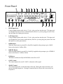
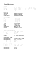
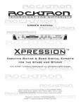
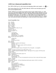
200 Watt Bass Amplifier
Instruction Manual
May be covered by one or more of the following: U.S. Patents
#4538297, 4647876, 4696044, 4745309, 4881047, 4893099, 5124657, 5263091,
5268527, 5319713, 5333201, 5402498 and 5493617.
Other patents pending. Foreign patents pending.
Your Rocktron Bass200 Bass Amplifier has been tested and complies with the following Standards
and Directives as set forth by the European Union:
Standard(s):
IEC60065 Professional Audio/Video or Similar
Equipment, EN55013:1997, EN61000-3-2 (1995)
EN61000-3-3(1995), EN55020:1995, CSA E65-94
This means that this product has been designed to meet stringent guidelines on how much RF
energy it can emit, and that it should be immune from other sources of interference when properly
used. Improper use of this equipment could result in increased RF emissions, which may or may
not interfere with other electronic products.
To insure against this possibility, always use good shielded cables for all audio input connections.
This will help insure compliance with the Directive(s).
Copyright © 2007 GHS Corporation
All Rights Reserved.
PRECAUTIONS
NOTE: IT IS VERY IMPORTANT THAT YOU READ THIS SECTION TO PROVIDE
YEARS OF TROUBLE FREE USE. THIS UNIT REQUIRES CAREFUL HANDLING.
• All warnings on this equipment and in the operating instructions should
be adhered to and all operating instructions should be followed.
• Do not use this equipment near water. Care should be taken so that objects
do not fall and liquids are not spilled into the unit through any openings.
• The power cord/adapter should be unplugged from the outlet when left
unused for a long period of time.
• Do not block any ventilation openings (if applicable). Install in
accordance with the manufacturer’s instructions.
• Do not install near any heat sources such as radiators, heat registers,
stoves or other apparatus (including amplifiers) that produce heat.
• Only use attachments/accessories specified by the manufacturer.
• Do not use this product with any case, stand, tripod, bracket or table that
is not specified by the manufacturer. Insure that the case, stand, tripod,
bracket etc. is properly adjusted and setup (follow all instructions). Extra
care and caution should be taken to avoid tip over and injury.
• Unplug this apparatus during lightning storms or when unused during
long periods of time.
Refer all service to qualified service personnel. Servicing is required when the apparatus has been
damaged in any way, such as power supply or plug is damaged, liquid has been spilled or objects have
fallen into the apparatus or if the apparatus has been exposed to rain or moisture, does not operate
normally or has been dropped.
DO NOT ATTEMPT TO SERVICE THIS EQUIPMENT. THIS EQUIPMENT SHOULD
BE SERVICED BY QUALIFIED PERSONNEL ONLY. DO NOT MAKE ANY
INTERNAL ADJUSTMENTS OR ADDITIONS TO THIS EQUIPMENT AT ANY
TIME. DO NOT TAMPER WITH INTERNAL ELECTRONIC COMPONENTS AT
ANY TIME. FAILURE TO FOLLOW THESE INSTRUCTIONS MAY VOID THE
WARRANTY OF THIS EQUIPMENT, AS WELL AS CAUSING SHOCK HAZARD.
OPERATING TEMPERATURE
Do not expose this unit to excessive heat. This unit is designed to operate between 32°
F and 104° F (0° C and 40° C). This unit may not function properly under extreme
temperatures.
WARNING: To reduce the risk of fire or electric shock, do not expose this unit to rain or moisture.
The lightning flash with an arrowhead symbol within an equilateral triangle is intended to alert the
user to the presence of un-insulated “dangerous voltage” within the products enclosure that may be
of sufficient magnitude to constitute a risk of electric shock.
The exclamation point within an equilateral triangle is intended to alert the user to the presence of
important operating and maintenance (servicing) instructions in the literature accompanying the
product.
GROUNDING INSTRUCTIONS
This product must be grounded (earthed). If it should malfunction or breakdown, grounding provides a path of least resistance for electric current to reduce the risk of electric shock. This product
is equipped with a supply cord having an equipment grounding conductor and a grounding plug. The
plug must be plugged into an appropriate outlet that is properly installed and grounded in accordance
with the local codes and ordinances.
DANGER - Improper connection of the equipment grounding conductor can result in a risk of
electric shock. Check with a qualified electrician or serviceman if you are in doubt as to whether the
product is properly grounded. Do not modify the plug provided with the product– if it will not fit the
outlet, have a proper outlet fitted.
The wires in this mains cord are colored in accordance with the following code:
Green & Yellow – Earth Blue – Neutral Brown - Live
Introduction
Congratulations on your purchase of the Rocktron Bass200 amplifier!
You will feel the low-end power and thump on this gig ready amp.
We have included many features into the Bass200:
o
High and Low Inputs
o
Gain and Master Volume Controls with clip indicating LEDs
o
Deep and Bright switch
o
5-Band EQ with an In/Out Switch
o
Built in advanced Compressor with an In/Out Switch
o
Effects Loop jacks on the front panel
o
Line Out Jack for direct recording or plugging into a PA.
o
Speed controlled fan drive circuit.
o
Switch on delay for silent power up.
o
Relay switched speaker output lines for silent power down.
Please follow all instructions in this manual for proper operation.
Enjoy!
Front Panel
1
HIGH Input Jack
Using a standard guitar cable with a 1/4” jack - plug your bass into this jack. This input jack
was designed for passive basses (without batteries), however, you may plug your active bass
into this input for a higher gain structure.
2
LOW Input Jack
Using a standard guitar cable with a 1/4” jack - plug your bass into this jack. This input jack
was designed for active basses (with batteries), however, you may plug your passive bass into
this input for a softer gain structure.
3
DEEP Button
When the Deep button is pressed IN, a fixed EQ is applied to the preamp to give a BASS
boost to the sound of +8dB at 50Hz.
4
BRIGHT Button
When he Bright button is pressed IN, a fixed EQ is applied to the preamp to give a TREBLE
boost to the sound of +10dB at 10k Hz.
5
EQ Button
This button switches the EQUALIZATION section IN or OUT.
6
GAIN Control
The control adjusts the overall “GAIN” or distortion of the signal.
7
SHAPE Control
This control adjusts the overall tonal shape of the EQ. Turning the control clockwise will
increase the high frequencies. Turning it counterclockwise will provide a boost to the low
frequencies.
8
BASS Control
This control provides a 15dB of cut or boost at 100Hz. Rotating this control clockwise will
increase the lower frequencies and, depending on other settings, will generally make your tone
warmer and heavier.
9
MID-LOW Control
This control provides approximately 15dB of cut or boost at 220Hz.
10
MID (MIDDLE) Control
This control allows your getting 15dB of cut or boost at 660Hz. Turn it clockwise, the sound
will be fatter and more powerful.
11
MID-HI Control
This control provides approximately 15dB of cut or boost at 1.6K Hz.
12
TREBLE Control
This control provides a 15dB of cut or boost at 5k Hz. Rotating this control clockwise will
increase the high frequencies producing a brighter sound.
13
COMPRESSOR Control
This controls the amount of signal compression. At the full counterclockwise position there is
no compression. At the full clockwise position there is full compression. The sonic effect of
compression is reduced dynamics, increased sustain and a more consistent output level regardless of how light or hard the strings are played.
14
VOLUME Control
This control determiners the overall level (output) of the amplifier.
15
POWER - On/Off Switch
This turns the amplifier on and off. When the switch is “lit” then the amplifier is “on”.
16
COMPRESSOR Button
Use this switch to turn ON or OFF the Compressor.
17
SEND Jack
Use this 1/4″ unbalanced jack to send signal to a professional outboard effects processor. Output level is approximately 0 dB to +4 dB and is post-EQ and post-shape but unaffected by the
setting of the volume control. It can also be used as a Line Out jack if required.
18
RETURN Jack
Use this 1/4″ unbalanced jack to return signal from a professional outboard effects processor.
This jack can also be used as a Line In Jack if required.
19
LINE OUT Jack
Use this jack for recording, direct to a PA system, or to a power amplifier.
Back Panel
20
AC POWER CORD
Using the included power cable connect the amplifier to a standard wall
outlet. See “Fuse Replacement” section for details on how to replace the
fuse.
21
SPEAKER OUTPUT Jack
The socket is situated on the rear panel of the unit. It connects to the internal speaker, you can also connect it to an external speaker cabinet.
22
COOLING FAN
It works with a speed controlled fan drive circuit. This reduces the
amount of fan noise as the fans run slow when the unit is cool and increase in speed with output power demands.
Fuse Replacement
We recommend that you use an authorized repair person to change the fuse
in this unit.
To access the fuse, first power down the unit and unplug the cable from the
wall outlet and the amplifier. Using a small screw driver, open the fuse tray
by prying open the small tab as shown in the drawing above.
Please note that the tray may not come all of the way out.
Remove the old fuse and replace with a comparable new fuse and close the
tray being sure that the tray snaps into position.
AC 117V 50/60 HZ
Fuse 6.3 @ 115V
AC 230V 50/60 HZ
Fuse 3.15 @ 230V
Specifications
INPUTS
High Input
Low Input
Effects Return
Impedance 3.9M Ohms
Impedance 10K Ohms
Impedance 4.7K Ohms
OUTPUTS
Effects Send
Line Out
Speaker Outputs
Impedance 4.7K Ohms
Impedance 22K Ohms
Min. impedance 4 Ohms
EQUALIZATION
Bass
Lo Mid
Middle
Hi Mid
Treble
Deep
Bright
Signal to Noise
Distortion
±15dB @ 100Hz
±15dB @ 220Hz
±15dB @ 660Hz
±15dB @ 1.6kHz
±15dB @ 5kHz
+8dB @ 50Hz
+10dB @ 10kHz
Better than 78dB
Less than 0.5% THD
GENERAL SPECIFICATIONS
Frequency Response
-3dB at 22 Hz and 25K Hz
Power Requirements
230 / 115V
Output Power:
200 Watts
Speaker
15” Custom Voiced Speaker
Dimensions and Weight:
Carton dimensions:
Carton dimensions:
Carton Gross weight:
Carton Gross weight:
560mm x 415mm x 730mm
22.25” x 16.5’ x 28.75”
33.58 kg
74 lbs
Dimensions and Weight
Bass200 dimensions:
Bass200 dimensions:
Bass200 weight:
Bass200 weight:
474mm x 334mm x 670mm
18.75 x 13.25 x 26.5
29.54 kg
65.1 lbs
Input range 150mV to 20V p-p
Input range 300mV to 40V p-p
Rocktron - A Division of GHS Corporation
2813 Wilber Ave.
Battle Creek MI 49037
USA
Tel: 1-269-968-3351
Fax: 1-249-968-6913
(8am to 5pm Eastern Standard Time)
www.rocktron.com
Rev. 12/26/07