1
®
Caution:
Read and follow
aH Safety Rumes
and mnstructions
Before Operating
This Equipment
5,0 HP
71 C
W
G Tm ES
UNTE
. Assembty
. Operation
. Customer Responsibilities
* Service and Adjustments
, Repair Parts
Sears,
Roebgck
and Co., Hoffman
Estates,
mL60179 U.SoA.
SAFETY RULES
Safe Operation
Practices
for Walk-Behind
TRAiNiNG
,
o
o
o
o
Read the Owner's Manual carefully, Be thoroughly
familiar with the controls and the proper use of the
equipment. Know how to stop the unit and disengage
the controls quickly.
Never allow children to operate the equipment Never
allow adults to operate the equipment without proper
instruction.
Keep the area of operation clear of atl persons, particularly small children, and pets.
o
o
o
o
o
PREPARATWON
o
,
•
o
o
o
o
o
o
o
Thoroughly inspect the area where the equipment is to
be used and remove al! foreign objects.
Disengage all clutches and shift into neutral before
staring the en.gine (motor).
Do not operate the equipment without wearing adequate outer garments. Wear footwear that will improve footing on slippery surfaces:
Handle fuel with care; it is highly flammable.
Use an approved fuel container.
Never add fuel to a running engine or hot engine.
Fill fuel tank outdoors with extreme care. Never fill fuel
tank indoors.
Replace gasoline cap securely and clean up spilled
fuef before restarting:
Use extension cords and receptacles as specified by
the manufacturer for nit units with electric drive motors
or electric starting motors._
Never attempt to make any adjustments while the
engine (motor') is running (except where specifically
recommended by manufacturer).
o
o
o
o
o
o
o
o
o
o
o
o
Rotary
Tillers
Keep children and pets away.
Do not overload the machine capacity by attempting to
tilt too deep at too fast a rate.
Never operate the machine at high speeds on slippery
surfaces. Look behind and use care when backing.
Never allow bystanders near the unit.
Use only attachments and accessories approved by
the manufacturer of the tiller (such as wheel weights,
counterweights, cabs, and the like).
Never operate the tWler without good visibility or light.
Be careful when tilling in hard ground. The tines may
catch in the ground and propel the tiller forward. If this
occurs, let go of the handlebars and do not restrain the
machine.
MAINTENANCE
AND STORAGE
Keep machine, attachments, and accessories in safe
working condition_
Check shear pins, engine mounting bolts, and other
bolts at frequent intervals for proper tightness to be
sure the equipment is in safe working condition.
Never store the machine with fuel in the fuel tank inside
a building where ignition sources are present, such as
hot water and space heaters, clothes dryers, and the
like. Altow the engine to cool before storing in any
enclosure.
Always refer to the operator's guide instructions for
important details if the tiller is to be stored for an
extended period.
° _MPORTANT
-CAUTIONS, IMPORTANTS, AND NOTES ARE A MEANS
OF ATTRACTING ATTENTION TO IMPORTANT OR
CRITICAL INFORMATION IN THIS MANUAL°
_MPORTANT: USED TO ALERT YOU THAT THERE IS A
POSStBILITY OF DAMAGING TNIS EQUfPMENT.
OPERATION
o
Powered
Do not put hands or feet near or under rotating parts.
Exercise extreme caution when operating on or crossing gravel drives, walks, or roads. Stay alert for hidden
hazards or traffic. Do not carry' passengers.
After striking a foreign object, stop the engine (motor),
remove the wire from the spark plug, thorough!y inspect the titler for any damage, and repair the damage
before restarting and operating the tiller.
Exercise caution to avoid slipping or fdting.
If the unit should start to vibrate abnormally, stop the
engine (motor) and check immediately for the cause.
Vibration is generally a warning of trouble.
Stop the engine (motor) when leaving the operating
position°
Take all possible precautions when leaving the ma.chine unattended.
Disengage the tines, shift into
neutral_ and stop the engine.
Before cleaning, repairing, or inspecting, shut Off the
engine and make certain all moving parts have stopped.
Disconnect the spark plug wire, and keep the wire
away from the plug to prevent accidental starting.
Disconnect the cord on etectric motors.
NOTE:
Gives essential information that wil! aid you to
better understand, incorporate, or execute a particular set
of instructions,
Look for this symbol to poht out important safety precautions,
it means
CAUTION!!! BECOME ALERT!!! YOUR
SAFETY mSJNVOLVEDo
CAUTION:
Always dJscon#ect spark
pBug w_re and place wire where it can°
not contact spark plug in order to prevent accidenta! starting when setting
up, transporting,
adiusting or making
repairs.
WARNING
&
The engine exhaust
from this product
contains chemicals
known to the State of California to cause cancer,
birth defects,
or other
reproductive
harm.
Do not run the engine indoors; exhaust fumes are
dangerous.
Never operate the tiifer without proper guards, ptates,
or other safety protective devices in place.
2
CONGRATULATIONS
on your purchase of a Sears Tiller'.
It has been designed, engineered and manufactured to
give you the best possible dependability and performance.
PRODUCT
HORSEPOWER:
5.0 HP
DISPLACEMENT:
9.03 cu. in. (!48cc)
GASOLINE CAPACITY:
4 Quarts
Unleaded Regular
OIL (APt-SF/SG) :
(CAPACITY: 20 oz.)
SAE 30 (Above 32°F)
SAE 5W_30(Be!ow 32°F)
SPARK PLUG :
(GAP: .030")
Champion
RJ 19LM (STD361458)
Should you experience any problems you cannot easily
remedy, please contact your nearest authorized Sears
Service CentedDepartment.
They have competent, welltrained technicians and the proper tools to service or repair
this unit.
Please read and retain this manual. The instructions will
enable you to assemble and maintain your tiller properly.
Always observe the "SAFETY RULES".
MODEL
NUMBER
SPEC_FICATIONS
917.295652
SERIAL
NUMBER
MAINTENANCE
AGREEMENT
A Sears Maintenance Agreement is available on this product. Contact your nearest Sears store for details.
DATE OF
PURCHASE
CUSTOMER
THE MODEL AND SERIAL NUMBERS WILL BE
FOUND ON THE MODEL PLATE ATTACHED TO
THE TOP OF THE TRANSMISSION.
YOU SHOULD RECORD BOTH SERIAL NUMBER
AND DATE OF PURCHASE AND KEEP tN A SAFE
PLACE FOR FUTURE REFERENCE.
RESPONSJBmLmES
o
Read and observe the safety rules.
o
Follow a regular schedule in maintaining, caring for and
using your tiller.
Follow the instructions
under the "Customer
Responsibilities" and "Storage" sections of this Owner's
Manual.
IMPORTANT:
THiS UNiT iS EQUIPPED WITH AN INTERNAL COMBUSTION
ENGINE AND SHOULD NOT BE USED ON
OR NEAR ANY UNIMPROVED
FOREST-COVERED,
BRUSH-COVERED
OR GRASS COVERED
LAND UNLESS THE
ENGINE'S
EXHAUST SYSTEM IS EQUIPPED WITH A SPARK ARRESTER
MEETING APPLICABLE
LOCAL OR STATE
LAWS (IF ANY). iF A SPARK ARRESTER
IS USED, IT SHOULD BE MAINTAtNED
iN EFFECTIVE WORKING ORDER BY
THE OPERATOR.
IN THE STATE OF CALIFORNIA
THE ABOVE tS REQUIRED BY LAW (SECTION 4442 OF THE CALIFORNIA
PUBLIC
RESOURCES
CODE),
OTHER STATES MAY HAVE SIMILAR LAWS.
FEDERAL LAWS APPLY ON FEDERAL
[_ANDS.
SEE YOUR SEARS AUTHORIZED
SERVICE CENTER!DEPARTMENT
FOR SPARKARRESTER.
REFER TO THE REPAIR
PARTS SECTION OF THIS MANUAL, FOR PART NUMBER.
UMJTEB TWO YEAR WARRANTY
ON CRAFTSMAN
TroLLER
For two years from date of purchase, when this Craftsman Tiller is maintained, lubricated, and tuned up according to
the operating and maintenance instructions in the owner's manual, Sears will repair free of charge any defect in
material or workmanship.
This Warranty does not cover:
o
Expendable items which become worn during normal use, such as tines, spark plugs, air cleaners and belts.
o
Repairs necessary because of operator abuse or negligence, including bent crankshafts
maintain the equipment according to the instructions contained in the owneCs manual.
•
if this Craftsman Tiller is used for commercial or renta! purposes, this Warranty applies for only 30 days from the
date of purchase.
and the failure to
WARRANTY SERVICE iS AVAILABLE BY RETURNING THE CRAFTSMAN TILLER TO THE NEAREST SEARS
SERVICE CENTER/DEPARTMENT
IN THE UNITED STATES° THIS WARRANTY APPLIES ONLY WHILE THIS
PRODUCT IS IN USE IN THE UNITED STATES°
This Warranty gives you specific legal rights, and you may also have other rights which vary from state to state°
SEARS, ROEBUCK AND CO., D/817 WA, HOFFMAN ESTATES,
3
ILLINOIS 60179
TABLE OF CONTENTS
MAmNTENANCE SCHEDULE .....................................
13
SERVICE & ADJUSTMENTS ................................
15-18
STORAGE ....................................................................
t9
TROUBLESHOOTING .................................................
20
REPAIR PARTS-TILLER .......................................
21-27
REPAIR PARTSoENG_NE ....................................... 28°33
SERViCE/PARTS ORDERING ............... BACK COVER
NDEX
A
Accessories ......................................
5
Adjustments:
Carburetor ................................... 18
Depth Stake ............................. ! 0
Handle Height .......................... t 5
Side Shie!ds ..........................
11
Throttle ....................................
18
Tines ......................................
17
Vo-Belt(Ground Drive) ............. 16
Ab Cleaner ....................................
!4
B
Belt:
Belt Guard ................................. ! 6
Repair Parts ............................. 22
V-.Belt (Ground Drive) ............. 16
R
14
11
,14
I5
12
I0
19
14
F
Fuel:
Fifling Tank ...........................
Storage ...................................
_ype ........................................
Finish:
Maintenance ...........................
1t
19
11
t5
H
C
Cooling System ............................. 14
Controls:
Choke ............................................ 9
Throttle ......................................
9
Drive (Tines) ............................. g
Cultivating ...................................... 12
Customer Responsibilities:
Air Cleaner .............................. t4
Cooling System ....................... 14
Finish ........................................ 15
Maintenance Schedule ........... ! 3
Muffler ...................................... 15
Oil Change ............................... 14
Spark Plug ................................ 15
Tines .......................................
t7
Transmission ......................... 15
V°Bett (Ground Drive) ............. 16
D
Depth Stake:
Adiustment ............................... 10
Repair Parts ............................. 25
E
Engine:
Air Cleaner ..............................
Cooling System .......................
Fuel Type ................................
Engine (cont'd)
Lubrication ...............................
Oi! Leve! ...................................
Oil Type ............................. 1t
Spark P_ug ..............................
Starting ...................................
Stopping ...................................
Storage ...................................
Winter Operation .....................
14
t4
11
Handle:
Height Adiustment ................... 15
Repair Parts ............................ 21
L
Lubrication:
Lubrication Chartol ................... t3
Engine ..................................... 14
M
Muffler:
Maintenance .......................... t 5
Spark Attester ........................... 3
O
Oil:
Level ....................................... 11
Type .......................... ......... !.1,14
Operation:
Cultivating ............................... 12
Fill Fuel Tank .......................... 11
Starting Engine ....................... 12
Stopping Tines & Engine ........ 10
Tilling ......................................
10
Til!ing Hints ............................. 12
Tine Operation ......................... 10
Transporting Tiller ................... 11
Winter Operation ..................... 14
4
Repair Parts:
Tiller ..................................... 2l-27
Engine ...............................
28°33
Rules for Safe Operation ................ 2
S
Service & Adjustments:
Carburetor ................................ t8
Handle Height ........................
15
Side Shields ............................ t I
Throttle ....................................
18
Tines ................ :...................... 17
V-Belt (Ground Drive) ............. 16
Wheels ..................................... 15
Service:
Repair Parts ....................... 21-33
Service Record ....................... 13
Shear Pins:
Operation ................................ !2
Repair Parts ........................
26
Spark Plug:
Gap ............................................
3
Maintenance ........................... 15
Storage:
Fuel System ............................
Tiller ........................................
19
19
T
Tiltin9 .................................... :_ 10,12
Tines:
Arrangement/Replacement
..... 17
Operation .................................. 10
Repair Parts ............................. 26
Shear Pins .............................. 12
Transmission:
Maintenance ........................... 15
Repair Parts ............................ 24
Troubleshooting ............................. 20
Transporting ................................... 11
W
Warranty ........................................... 3
Wheels:
Removal ..................................
15
Repair Parts ............................. 23
IES
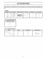
These accessories were availabUe when the tiller was purchased, They are 8JSOavailabme at most Sears Retail out_ets
and Service Centers. Most Sears Stores can order repair parts for you when you provide the model number of your
tiller,
ENGINE
SPARK
PLUG
MUFFLER
AR
F_LTER
GAS CAN
ENGINE
OiL
STABmLIZER
\il_ i'<_i /
TILLER
PERFORMANCE
FURROW
OPENER
J"
/
,{
!
/
/
(
//
---
TroLLER MAmNTENANCE
BELT
TINES
SHEAR
5
P_N
HAIRPEN
CUP
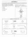
Your new tiller has been assembled at the factory with exception of thOse parts left unassembled for shipping purposes, To
ensure safe and proper ooeration of your tiller all parts and hardware you assemble must be hghtened securely, Use the
correct tools as necessary to insure proper tightness,
TOOLS REQUIRED
FOR ASSEMBLY
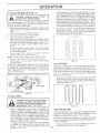
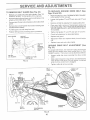
OPERATOR'S
PO%T_ON
(See Fig. 1}
When right or left hand is mentioned in this manua! it
means when you are in the operating position (standing
behind titler handles),
A socket wrench set will make assembly easier. Standard
wrench sizes are isted.
(I) Utility knife
(i) Wire cuttel
FRONT
(1) Screwdriver
(1) Tire oressure gauge
(!) Pair of pliers
(1) 9/16" wrench
LE_
RIGHT
OPEF_ATOR'S
POSIT_ON
RG., t
CONTENTS
(2) Handle Locks
(I) Flat Washer t3/32 x 1 x tl Ga.
(2) Hairpin Clips
OF HARDWARE
PACK
(2) Carriage Bo!ts 3/8-t6 UNC x ! Gr. 5
(1) Cable Clip
(1) Pivot BoJt
3/8o16 UNC Grade 5
6
(2) Center Locknuts 3/8_16 UNC
(1) Handle Lock Lever
Extra Shear Pins
LY
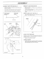
UNPACKING
CARTON
Grasp handle assembly° Hold in "up" position. Be sure
handle lock remains in gearcase notch. Slide handle
assembly into position.
(See Fig. 2)
U of exposed
staples when handNing or disposing of
_
_
HANDLE ASSEMBLY
"UP" POSiTiON
_teriaL
IMPORTANT:
TILLER,
BE
CABLES.
WHEN
CAREFUL
UNPACKING
ANDASSEMBUNG
NOT TO STRETCH
OR KINK
o
While holding handle assembly, cut cable ties secudng
handle assembly to top frame and depth stake, Let
handle assembly rest on tiller.
o
Remove top frame of carton.
•
Slowly ease handle assemUy up and place on top of
carton.
HANDLE
LOCK LEVER TO
HOLD
LOOSEN HANDLE
LOCK LEVER TO
MOVE
Cut down right hand front and right hand rear corners
of carton, lay side carton wall down.
o
Remove packing material from handle assembly.
o
Separate shift rod from handle assembly:
FiG. 4
SHIFT ROD
o
Rotate handle assembly down. insert rear carriage
bolt first, with head of bolt on L.H. side of tiller and
loosely assemble locknut. (See Fig. 5)
hsert pivot bolt in front part of plate.
®
Cut down rear' panel of carton.
Lower the handle assembly, Tighten bolts so handte
moves with some resistance. This will al!ow for easier
adjustment.
Place flat washer on threaded end of handte lock !ever.
/
Insert handle lock tever through handle base and
gearcase, Screw in handle lock lever just enough to
hold lever in place.
J
HANDLE
ASSEMBLY
fflsert second handle lock (with teeth inward) in the slot
of the handle base (just inside of washer)
F_G. 2
WNSTALL HANDLE
o
With handle assembly in lowest position, securely
tighten handle lock lever by rotating clockwise. Leavo
ing handle assembly in lowest position wil! make it
easier to remove tiller from carton.
(See Figs, 3, 4, and 5)
hlsert one handle lock (with teeth facing outward) in
gearcase notch. (Apply grease on smooth side of
handle lock to aid in keeping lock in place until handle
assembly is lowered into position.)
REAR
CARRIAGE
BOLT
VIEW FRO_I R.Ho SMDE OF T_LLER
\
HANDLE
HANDLE
LOCK
GEARCASE
FLAT
WASHER
SLOT
i
HANDLE
LOCK
LEVER
ASSEMBLY
GEAROASE
NOTCH
HANDLE
HANDLE
BASE
LOCKNUT
RG. 5
7
PIVOT
BOLT
LY
ASSE@
CONNECT
SHIFT
ROD (See Fig, 6)
REMOVE
T_LLER FROM CRATE
o
Insert end of shift rod farthest from bend into hole of
shift lover indicator.
o
Make sure shift _ever indicator is in "N" (neutral) position (See Fig. 6)
•
o
Insert hairpin dip through hole of shift rod to secure.
hsert other end of shift rod into hole in shift lever.
o
Tilt tiller forward by lifting handle° Separate cardboard
cover from leveling shield,
o
Insert second hairpin clip through hole of shift rod.
o
Rotate tiller handle to the right and pull titler out of
carton.
ATTACH TH_S
END TO SH{R °
ATTACH TH_S END
TO SH_FT LEVER
_NSERT CABLE
o
CUP
(See Fig. 7)
Insert plastic cable clip into hole on the back of handle
column. Pu,_n cables into clip,
COLUMN
HANDLE
////
CABLES
DABLE CUP
RG, 7
CHECK
T_RE PRESSURE
The tires on your unit were overinflated at the factory for
shipping purposes,
Correct and equal tire pressure is
important for best tilling ped_ormanco.
o
SH_FT
Reduce tire pressure to 20 PS1.
HANDLE
o
_/
HNRPIN
CUP
SHIFT ROD
RGo 6
8
HEIGHT
Handle height may be adjusted to better suit operator.
(See "TO ADJUST HANDLE HEIGHT" in the Service
and Adjustments section of this manua!).
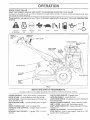
KNOW YOUR TILLER
READ THIS OWNER'S
r_ANUAL AND SAFETY RULES BEFORE OPERATING
YOUR TJLLERo
Compare the illustrations with your filler to familiarize yourself with the location of various controls and adjustments, Save
this manual for future reference.
These symboJs
meaning.
may appesr on your Til_er or in literature
supplied
with the product.
Learn and understand
their
RUN
CAUTION
OR WARNING
ENGINE
ON
ENGINE
OFF
FAST
SLOW
CHOKE
FUEL
OIL
STOP
0
THROTTLE
CONTROL
BAR
SP_FT LEVER
CHOKECONTROL
FUEL SHUT-OFF
VALVE
SH_FT LEVER
INDICATOR
t
/
DEPTH STAKE
LEVEUNG
SHIELD
STOP SW_TCH
OUTER
S_DE
SHELD
FiG° 8
MEETS ANS_ SAFETY
REQUIREMENTS
Our tillers conform to the safety standards of the American National Standards Institute.
CULTmVATING SHIELDS o Engages tines
LEVELING SHIELD - Levels tilled soil.
OUTER SIDE SHIELD - Adjustable to protect small ptants
from being buried.
RECOIL STARTER HANDLE o Used to start the engine,
SHIFT LEVER - Used to shift transmission gears,
SHIFT LEVER iNDiCATOR oShows which gear the transo
mission is in,
THROTTLE CONTROL - Controls engine speed,
STOP SW_TCH - Used to stop engine. Must be in "ON"
position when starting engine.
CHOKE CONTROL _ Used when starting a cold engine.
DEPTH STAKE o Controls depth at which tiller wilt dig,
DEPTH STAKE - Controls forward speed and the depth at
which the tiller win dig.
DEPTH STAKE PIVOT _ Controls pivoting action of depth
stake,
DRIVE CONTROL BAR --Used to engage tines.
FORWARD T_NE CONTROL o Engages tines in forward
direction.
REVERSE TINE CONTROL o Engages tines in reverse
direction.
9
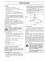
PE
The operation of any tiller can result in foreign objects thrown into the eyes, which can
result in severe eye damage.
Ab,'_ays wear safety g_asses
or eye shields
before starting
your tiller and while tH_ingo We recommend
a wide vision safety mask over the spectacles
or standard safety 9_asseso
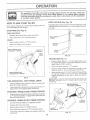
HOW TO USE YOUR TILLER
DEPTH
Know how to operate all controls
oil or attempting to start engine.
The depth stake can be raised or lowered to allow you more
versati!e tilling and cultivating, or to more easily transport
your tiller.
STOPPING
before adding fuel and
STAKE
(See Fig, 10)
(See Fig. 9)
TINES AND DRIVE
•
•
_'_"
ReEease drive control bar to stop movement,
Move shift lever to "N" (neutral) position.
SHALLOWEST
T_LL_NG
TRANSPORT
POS_TION
_
ENGINE
o
Move throttle centre! to "STOP" position.
o
Never use choke to stop engine.
DEEPEST _/_'*
TtLL_NG
DRIVE CONTROL, BAR
"ENGAGED" POSITION
THROTTLE
STAKE
DEPTH __
SHIFT
LEVER
F1Got 0
TILUNG
/
\"
DRIVE CONTROL BAR
"DISENGAGED"
POSJT_ON
F_Go9
T_NE OPERATION
° WtTH WHEEL
(See
o
Re.lease depth stake pin, Putl the depth stake up for
increased tilling depth. Place depth stake pin in hole of
depth stake to lock in position,
o
Place shift lever indicator in "T" position.
o
HoJd the drive control bar agains_ the handle to start
tilling movement. Tines and wheels witl both turn.
o
Move throttle control to "FAST" position for deep tilting.
To cultivate, throttle control can be set at any desired
speed, depending on how fast or slow you wish to
cultivate.
ItMPORTANT:
ALWAYS RELEASE DRIVE CONTROL BAR
BEFORE
MOVING
SHIFT
LEVER
_NTO ANOTHER
POSITION.
DR!VE
Always release drive control bar before moving shift
lever into another position,,
o
o
DEPTH STAKE P_N
"RELEASED"
POSIT_ON
TiRe movement is achieved by moving shift lever to"T"
(till) position and engaging drive control bar,
FORWARD
°WHEELS
Fig. 11)
ONLYP£1NES STOPPED
Release drive control bar and move shift lever indicator
to "P (forward) position. Engage drive contro! bar and
tiller wilt move fopNard.
REVERSE
o WHEELS
ONLYzTmNES STOPPED
*
DO NOT STAND DIRECTLY BEHIND T!LLER.
o
Release the drive controt bar.
o
Move throttle controt to "SLOW" position.
o
Move shift lever indicator to "R" (reverse) position.
o
Hold drive control bar against the- handle to start tiller
movemertto
NUT "A"
OUTER
S_DE SHIELD
FIG. 11
10
Engine oil should be to point of overflowing.
For
approximate capacity see "PRODUCT SPECiFiCATIONS" on page 3 of this manual. All oil must meet
A.P.I. Service Classification SF or SG.
TURNmNG
o
Release the drive controJ bar.
o
Move throttle control to "SLOW" position.
Place shift lever indicator in "F" (forward) position.
Tines will not turn.
o
Lift handle to raise tines out of ground.
Swing the handle in the opposite direction you wish to
turn, being careful to keep feet and legsaway from
tines.
When you have completed your turnoaround, release
the drive control bar and lower handle. Place shift lever
in "T" (till) position and move throttle control to desired
speed. To begin tilling, hold ddve control bar against
the handle.
OUTER
SIDE SHELDS
o
For cold weather operation you should change oil for
easier starting (See oil viscosity chart in the Customer
Responsibilities section of this manual).
o
To change engine oil, see the Customer Responsibilities section in this manual.
OiL
(See Fig. 11)
The front edges of the outer side shields are slotted so that
the shields can be raised for deep tilling and lowered for
shallow tilling to protect small plants from being buried.
Loosen nut 'W' in slot and nut "B", Move shield to desired
position (both sides). Retighten nuts.
NLLER
PLUG
DRA_N
PLUG
FIGo 12
TO TRANSPORT
ADD GASOMNE
Fill fuel tank. Use fresh, clean, regular unleaded
gasoline. (Use of leaded gasoline will increase carbon
and tend oxide deposits and reduce valve life.)
_MPORTANT: WHEN OPERATING IN TEMPERATURES
92 allow tiller engine and muff_er to
col Disconnect spark p_ug wire. Prain
AUTION: Before _ifting or transpo_l.asoHne from fuel tank.
BELOW
AROUND THE YARD
o
Release the depth stake pin. Move the depth stake
down to the top hoie for transporting the tiller. Place
depth stake pin in hole of depth stake to lock in position°
This prevents tines from scuffing the ground°
o
Place shift lever indicator in "F" (forward) position for
transporting.
o
Hold the drive control bar against the handle to start
tiller movement. Tines win not turn,
o
Move thrattle control Io desired speed.
Disconnect spark ptug wire.
o
Drain fuel tank,
ENGINE
#aPORTANT:
BE VERY CAREFUL NOT TO ALLOW DIRT
TO ENTER THE ENGINE WHEN CHECKING OR ADDING
OiL OR FUEL. USE CLEAN OIL AND FUEL AND STORE
iN APPROVED,
CLEAN, COVERED CONTAINERS.
USE
CLEAN FiLL FUNNELS.
CHECK
ENGINE
OiL LEVEL
The engine in your unit has been shipped, from the
factory, already filled with SAE 30 summer weight oil.
o
With engine level, clean area around oil filler plug and
remove plug.
CLEAN,
WINTER
GRADE
Do not overfill
Wipe off any spilled oil
or fuel Do not store, spi!l or use gasoline near an open flame.
(See Fig. 12)
o
USE FRESH,
CAUTION: FiN to within 1/2 inch of top
of fuem tank to prevent, spH_s and to
allow for fuel e×pans_Ono If gasoline is
accidentally
sp_Hed, move machine
away from area of spi& Avoid creating
any source of ignition until gasoline
vapors have disappeared.
Transport in upright position to prevent oil leakage°
BEFORE STARTING
(0_C),
WARNING:
Experience indicates that alcohol blended
fuels (catled gasohol or using ethanol or methanol) can
attract moisture which leads to separation and formation of
acids during storage_ Acidic gas can damage the fueJ
system of an engine while in storage° To avoid er_gine
probtems_ the fue_ system should be emptied before
storage of 30 days or !ongero Drain the gas tank, start the
engine and let it run until the fuet lines and carburetor are
empty. Use fresh fue_ ne×t season° See Storage section
of this manuat for additional information. Never use engine
or carburetor cleaner products in the fuel tank or permanent
damage may occur.
AROUND TOWN
o
32°F
GASOLINE TO HELP iNSURE GOOD COLD WEATHER
STARTING.
11
E
TO START
l
ENGtNE
N¸
(See Fig, 17)
CAUTHON: Keep tine control
Soit conditions are important for proper tilting. Tines witf
not readily penetrate dry, hard soit which may contribo
ute to excessive bounce and difficult handling of your
tiIIer, I_4ard soil shouid be moistened before tilling;
however, extremely wet soil will "baItoup" or clump
during tilling, Wait until the soil is less wet in order to
achieve the best results. When tilling in the fall, remove
vines and long grass to prevent them from wrapping
around the tine shaft and stowing your ti_ling operation.
in "OFF"
When starting engine for the first time or if engine has run
out of fuel, it wil! take extra pulls of the recoil starter to move
fuel from the tank to the engine.
o
Make sure spark plug wire is properly connected and
access cover is completely closed to create proper
seat.
o Place throttle contro! in "FAST" position:
o Turn fuel shutooff valve to "ON" position.
o Push stop switch to "ON" position.
o With engine fu!ly choked, grasp recoil starter handle
with one hand and grasp tilter handle with other hand.
Pull rope out slowiy until engine reaches start of corn-.
pression cycle (rope wili pull slightly harder at this
point).
o Pull recoil starter handle quicklyo Do not let starter
handle snap back against starter. Repeat if necessary
in half choked position.
o When engine starts, s!ow!y move choke control to
"RUN" position as engine warms up.
NOTE: A warm engine requires Iess choking to start.
o Move throttle control to desired running position.
o Al!ow engine to warm up for a few minutes before
engaging tines.
NOTE: tf at a high attitude (3000 feet) or in cold temperatures (below 32°F), the carburetor fuel mixture may need to
be adjusted for best engine performance° See "TO ADJUST CARBURETOR" in the Service and Adjustments
section d this manual.
NOTE: !f engine does not staR, see troubleshooting points.
o
Do not lean on handle. This takes weight off the wheeis
and reduces traction. To get through a really tough
section of sod or hard ground, apply upward pressure
on handle or lower the depth stake.
F_G.14
CULTiVATiNG
Cultivating is destroying the weeds between rows to prevent them from robbing nourishment and moisture from the
plants. At the same time, breaking up the upper layer of soil
crust wi!! help retain moisture in the soil. Best digging depth
is 1" to 3". Lower the outer side shields to protect small
plants from being buried.
o
Cultivate up and down the rows at a speed which witl
al!ow tines to uproot weeds and leave the ground in
rough condition, promoting no further growth of weeds
and grass (See Fig. 15).
, f
CHOKE
..
i
CONTROL
FiG. 13
I
,
',,.j
_| i•r_....
T_LL_NG HINTS
i f_-
.x
I\.>
/'", I
\\., _ |
>
l_.,
handling your tiller, start actuaJ fie_d
use
w_th throttle
in s_ow
position (midCAUTION:
UntiJ you
are accustomed
to
F{G. 15
•
Tilling is digging into, turning over, and breaking up
packed soit before planting. Loose, unpacked soil
helps r-oot growth. Best tilling depth is 4" to 6". A tiller
will also clear the soil of unwanted vegetation. The
decomposition of this vegetable matter enriches the
soil Depending on the climate (rainfall and wind), it
may be advisable to till the soft at the end of the growing
season to further condition the soil
,_ For easier handling of your tilter, leave about 8 inches
of untilted soil between 'the f;mt and second ti_irlg
passes. The third pass will be between the first and
t2
second (See Fig. 14).
T_NE SHEAR
PiNS
The tine assemblies on your tiller are secured to the tine
shaft with shear pins (See "TINE REPLACEMENT" in the
Service and Adjustments section of this manual)°
If the tiller is unusually overloaded or jammed, the shear
pins are designed to break before internal damage occurs
to [he transmission.
o
tf shear pin(s) break, reptace only with those shown in
the Repair Parts section of this manual
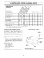
MAnNTENANCE
SCHEDULE
FiLL IN DATES
AS YOU COMPLETE
REGULAR SERVICE
SERVMCE
DATES
Check Engine Oil Level
Change Engine Oil
Oil Pivot Points
Inspect Spark Arrester / Muffler
Inspect Air Screen
Clean or Replace Air Cleaner Cartridge
Clean Engine Cylinder Fins
RepJace Spark Plug
1 - Change
2 - Service
GENERAL
more often when operating
more often when operating
under a heavy load or in high ambient
in dirty or dusty conditions.
temperatures.
LUBRiCATiON
RECOMMENDATIONS
CHART
The warranty on this tiller does not cover items that have
been subjected to operator abuse or negligence.
To
receive fu!l value from the warranty, the operator must
maintain tiller as instructed in this manual.
* THROTTLE
CONTROL
Some adjustments wiil need to be made periodically to
properly maintain your tillero
AIt adjustments in the Service and Adjustments section of
this manual should be checked at least once each
** ENGINE
season,
.....
Once a year you shoutd replace the spark plug, clean
or replace air fiiter, and check tines and belts for wear.
A new spark plug and clean air filter assure proper air°
fuet mixture and help your engine run better and last
longer.
BEFORE
EACH
.....
* LEVELING
{]ELD
HINGES
USE
o
Check engine oil levei.
o
Check tine operation.
Check for toose fasteners.
* iDLER
BRACKET
HUB
LUBRmCATmON
Keep unit well lubricated (See "LUBRICATION
* DEPTH STAKE
P_N
* SAE 30 OR 10W-30 MOTOR OIL
CHART").
** REFER TO CUSTOMER
13
RESPONSltBILtT_ES
"ENGINE"
SECTION
ESPO
E
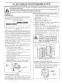
ENGMNE
LUBRIOAT_ON
Use only high quatity detergent oil rated with API sewice
classification SF or SG Select the oil's SAE viscosity grade
accBrding to your expected temperature.
SAE ViSCOSn_"
°F
.20 '/
TEMPERATURE
0°
RANGE
30°
32 °
GRADES
40 °
ANTICIPATED
60 °
BEFORE
80 °
100 <1
NEXT OIL CHANGE
FIG, 16
NOTE: A_though mu!tioviscosity oils (5W,G0, 10W_30_etc.)
improve starting in cold weather, these multJoviscosJty oils
will result in increased oi! consumption when used above
32°F (0°C). Check your engine oil level more frequent!y to
avoid possible engine damage from running tow on oil.
Change the oil after the first two hours of operation and
every 25 hours thereafter or at least once a year if the tiller
is not used for 25 hours, in one yeaL
Check ti_e crankcase oil level before staffing the engine
and after each five (5} hours of continuous use. Add SAE
30 motor oil or equivalent, Tighten oit filler plug securely
each time you check the oil level
TO CHA,NGE ENGHIE O_L (See Figs° 1¢ and 17)
Determine temperature range expected before oil change.
A_ oit must meet AP_ service c!assificaf!on SF or SG.
o Be sure titler is on _evel sudaceo
_, Oil will drain more freely when warm.
o
Use a funnel to prevent oi! spill on tiller, and catch oi! in
a suitable container.
o
Remove drain ptug, For easier removal of piug use
7/!6 12 Pt. socket with extension.
o Tip tilter forward to drain oil.
o After oii has drained completely, replace oil drain plug
and tighten securely.
•
Remove oil filler plug. Be Careful not to atlow dirt to
enter the engine,
o Refill engine with oiL. See "CHECK ENGINE OtL
LEVEL" in the Operation section of this manual
--O,LLEWL
LITIES
Service air .cleaner more often under dusty conditions.
o Loosen air cteaner cover screws. Remove cover and
air cleaner assembly from base.
o Remove air cleaner asssembly from inside cover and
disassemble.
TO SERVICE PRE--CLEANER
o Wash it in liquid detergent and water.
o Squeeze it dry in a clean cloth.
o Saturate it in engine oil Wrap it in clean, absorben£
ctoth and squeeze to remove excess oil.
TO SERVICE CARTRIDGE
o
Gently tap the flat side of the paper cartridge to dis.o
lodge dirt. Do not wash the paper cartridge or use
_ressurized air, as this wilt damage the cartridge.
eplace a dirty, bent, or damaged cartridge.
!nsert tabs on cover into slots in base and tighten cover
screws securely.
CAU'T_ON: Petroleum so,vents, such
as kerosene, are _ot to be used to c_ea_s
cartridge.
They may cause deterioratie_ of the cartridge° Do not oi_ car°
tr_dgeo Do _ot use press_arized a_r to
c_ean or dry cartridge.
PREoCLEANER
RETAINER
COVER
/
'
L
I
_
SL'OT
A_R CLEANER
F_Go 18
COOLING
SYSTE_
(See Fig. 19)
Your engine is air cooled. For proper engine pedormance
and long life keep your engine clean.
o Clean air screen frequently using a stiff-bristled brush.
o
Remove blower tsousing and dean as necessary.
°
Keep cylinder fins free of dirt and chaff.
X\O_L FILLER
PLUG
FIG, 17
AmR F_LTER (See Fig. 18)
Your engine will not run properly using a dirty air filter.
Clean the foam pre,ocleaner after e"ery 25 hours of opera °
fion or every season. Service paper cartridge every 100
hours of operation or every season, whichever occurs first. 1 4
i_il
BASE
SCREWS
DUAL ELEMENT/CARTRiDGE
¢ .... .:',
,
TAB
CARTRIDGE
F_G°19
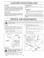
MER R
L
MUFFLER
TRANSMISSION
Do not operate tiller without muffler. Do not tamper with
exhaust system. Damaged mufflers or spark arresters
could create a fire hazard. Inspect periodically and replace
if necessary, If your engine is equipped with a spark
attester screen assembly, remove every 50 hours for
cleaning and inspectiono Replace if damaged.
Your transmission is sealed and will only require iubdcation
if serviced.
o
Clean engine, wheels, finish, etc. of all foreign matter.
SPARK
o
Keep finlshed surfaces and wheels free of all gasoline,
oil, etc.
CLEANING
PLUG
Replace spark plugs at the beginning of each titling season
crafter every 50 hours of use, whichever comes first. Spark
plug type and gap setting is shown in "PRODUCT SPECto
FICATIONS" on page 3 of this manual.
S
Protect painted surfaces with automotive type wax.
We do not recommend using a garden hose to clean your
unit unless the muffler, air filter and carburetor are covered
to keep water out° Water in engine can result in a shortened
engine life.
E
CAUTION: Disconnect
contact with _mo_
J
spark pk,_g wire from spark pJug and p_ace wire where it cannot come into
1
J
TILLER
TO RENJOVE WHEEL
(See Fig. 21}
o
Place blocks under transmission
tipping.
Select handle height best suited for your tilling conditions.
Handle height wilt be different when tiiJer digs into soil
o First loosen handle lock lever°
o
Remove outer side shield by removing nuts"A" and "B".
o
Remove inner side shield by removing nuts "C" and
o
Handle can be positioned at different settings between
"HIGH" and "LOW" positions.
o
o
Remove hairpin clip and clevis pin from wheel
Remove wheel and tire.
o
Retighten handle lock _ever securely after adjusting_
o
Repair tire and reassemble.
TO ADJUST
HANDLE
HEIGHT
(See
Fig.
20)
HANDLE (H_GN
POS_T_ON}
CLEVIS
HANDLE
LOCK
LEVER
HANDLE (LOW
POSXT_ON)
HAIRPIN
CMP
FiG, 20
TIRE CARE
CAUTION: When mounting tires, uric
less beads are seated, overinftation
can cause an e×ptosion.
o
Maintain 20 pounds of tire pressure° If tire pressures
are not equal, tiller will pull to one side.
o
Keep tires free of gasoline or oil which can damage
rubber.
FiG° 21
15
to keep tiller from
V CE AND
TO REMOVE
o
BELT GUARD
E
ADJ
TO REPLACE
GROUND
Figs. 22 and 23)
(See Fig_ 22)
Remove LH. inner and outer side shields (See "TO
REMOVE WHEEL" in this section of this manual}
DRIVE
BELT
(See
o
Remove hairpin clip and clevis pin from left wheel. Pull
wheel out from tiller about 1 inch.
Remove bett guardo (See'q'o REMOVE BELTGUARD"
in this section of this manual),
+
Loosen belt guides "A" and "B" and also nuts "C" and
o
Remove two (2) cap nuts and washers from side of be!t
guard.
o
Remove old belt by slipping from engine pulley first.
o
o
o
Remove hex nut and washer _rom bottom of belt guard
(loca(:ed beMnd wheel)
Pull belt guard out and away from unit°
Place new belt in groove of transmission pulley and
into engine pulley. BELT MUST BE IN GROOVE ON
TOP OF IDLER PULLEY. NOTE POSitiON OF BELT
TO GUIDES.
o
Replace belt guard by reversing above procedure,
BELT GUARD
Tighten belt guides "A" and "B" and nuts "C" and "D',
CAPNUT
AND WASHER
HEX NUT
AND
WASHER
(LOCATED
BEHIND
_RE_
o
Check belt adjustment as described below.
o
Replace belt guard,
o
Reposition wheel and replace clevis pin and hairpin
clip.
o
Replace inner and outer side shields.
GROUND
Fig. 23)
DR_VE BELT
ADJUSTMENT
For proper belt tension, the extension spring should have
about 5/8 inch stretch when drive control bar is in "ENGAGED" position. This tension can be attained as follows:
CAP NUT
AND WASHER
o
Loosen cable clip screw securing the drive control
cable.
o
Slide cable forward for less tension and rearward for
more tension until about 5/8 inch stretch is obtained
while the drive control bar is engaged.
o
Tighten cable clip screw securely.
F_G. 22
BR_VE
CONTROL
CABLE
NUT"D"
LESS
TENSION
_DLEB
PULLEY
(See
EXTENSION
SPRmNG
TRANSMiSSiON
PULLEY
F_G. 23
16
OK AN© ADJU
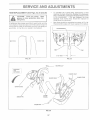
T_NE REPLACEB]ENT
To maintain the superb tilling performance of this
machine the tines should be checked for sharpness,
wear_ and bending, particularly the tines which are next
to the transmission,
tf the gap between the tines
exceeds 3ot/2 inches they should be replaced or
straightened as necessary.
(See Figs, 24._25 and 26)
OAUT_OH:
Ti_ses are sharpo Wear
g_oves or othe_ protection when hanod_ing tines°
o
A badly worn tine causes your tiller to woi-k harder and dig
more shallowo MesI important, worn tines cannot chop and
shred organic matter as effectively nor bur7,it as deeply as
good tines,, A tine this worn needs to be replaced.
New tines should be assembled as shown in Fig. 26.
Sharpened fine edges will rotate _earward from above.
WORN WINE
3,°1/2 '" _£AX ............_-q
FtGo 24
FK_, 25
HAiRPiN CU} ,:_
!
COUNT_zR
T_NE
SHARP EDGE
SHEAR PiN
SHEARPIN
FIGo28
17
CE AND
F_NAL SETTING
ENGINE
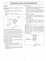
TO ADJUST THROTTLE
(See Fig. 27)
CONTROL
o
Loosen cable damp screw to allow cable to move
o
Move throttk_ control lever on upper handte to "FAST"
position.
Puff throttle cable out to end of travel
o
o
o
Start engine and allow to warm for five minutes. Make
final adjustment:s with engine running at idle and drive
control bar in "DISENGAGED" position.
o
With throttle control lever in "SLOW" position, turn idle
needte valve in (clockwise) until engine begins to die
then turn out (counterclockwise)
unti! engine runs
rough° Turn vaive to a point midway between those two
positions.
CABLE
_DLE RPM ADJUST_v_ENT
HDld cable in this position and tighten clamp screw
securely.
To adiust idle RPM_ rotate throttle linkage counterclockwise and hold against stop whi!e adjusting idle
speed adiusting screw to obtain 1750 RPM. Release
throttle linkage°
THROTTLE
CABLE
ACCELERATION
o
F_Go27
CARBURETOR
(See Fig, 28)
The carburetor has a high spec'd jet and ha.s been preset at
the factor€ and adjustment should not be necessary. However, minor adjustments may be required to compensate
for differences in fue!: temperature, altitude or toad. If the
_..,_ ......+_,_,4,.
....... _ o__,,_'-¢,_,_ntproceed as follows.
i
In general, turning the idle needle valve in (clockwise)
decreases the suppty of fuet Io the engine giving a leaner
fuel/air mixture. Turning the needle valve out (counterclockwise) increases the supply of fuel to the engine giving
a richer fuet!air mixture°
_MPORTANT:
DAMAGE TO THE NEEDLES AND THE
SEATS IN CARBURETOR MAY RESULT tF SCREWS ARE
TURNED tN TOO T_GHT
PREUMINARY
o
o
o
Move throttle control lever from "SLOW" to "FAST"
position. If engine hesitates or dies, turn needle valve
out (counterclockwise)
I/8 turn.. Repeat test and
continue to adjust, if necessary, until engine acceleP
ares smoothly.
High speed stop is factory adjusted.
Do not adiust or
damage may resu!L
_MPORTANT:
NEVER TAMPER WITH THE ENGINE
GOVERNOR, WHICH IS FACTORY SET FOR PROPER
ENGINE SPEED. OVERSPEEDINGTHEENGtNEABOVE
THE FACTORY
HIGH SPEED SETTING
CAN BE
DANGEROUS. IF YOU "THINK THE ENG1NE_GOVERNED
HIGH SPEED NEEDS ADJUSTING, CONTACT YOUR
NEAREST
AUTHORIZED
SERVICE
CENTER!
DEPAF_TMENT,
WHICH HAS THE PROPER EQUIPMENT
AND EXPERIENCE
TO MAKE ANY NECESSARY
ADJUSTMENTS.
CLAMP SCREW
TO ADJUST
TEST
SETTING
Air cleaner assembly must be assembled to the carburetor when making carburetor adjustments.
Be sure the throttte control cable is adjusted properly
(see above).
_DLE NEEDLE VALVE
FIGo 28
With engine off, turn idle needle valve in (clockwise)
closing it finger tight and then turn valve out (counterclockwise) 1ol/2 turns.
18
E
ENGINE
Immediately prepare your titler for storage at the end of the
season or if the unit will not be used for 30 days or more°
Drain oil (with engine warm) and replace with clean oit,
(See "ENGINE" in the Customer Responsibilities section of
this manuat),
CAUTI1ON: Never store the tiller with
gasoline in the tank inside a buitding
where fumes may reach an open flame
or spark°
AHow the engine to ceo_
before storing ir_ any encUosure,
CYUNDERS
o
Remove spark pkJg,
o
Pour I ounce (29 mI) of oi! through spark piug hote into
cytindero
Putt starter handle slowly severa! times to distribute oil,
o
Replace with new spark plug.
o
Do r_ot store gasoline
o
Replace your gasoline can if your can starts to rust,
Rust and/or dirt in your gasoline will cause p_oblems.
o
If possible, store your unit indoors and cover it to give
protection from dust and dirt.
T LLER
o
Clean entire tiller (See "CLEANING" in the Customer
Responsibilities section of this manua!),
o
Inspect and replace be!ts, if necessary (See belt reo
placement instructions in the Service and Adjustments
section of this manual)°
Lubricate as shown in the Customer Responsibilities
section of this manuat.
o
Be sure that all nuts, bolts and screws are securely
fastened° !nspect moving pails for damage, breakage
and wear, Replace if necessary,
o
o
ENGINE
FUEL SYSTE_v'_
_MPORTANT:
IT IS IMPORTANT TO PREVENI _ GUM
DEPOSITS FROM FORMING IN ESSENTIAL FUEL
SYSTEM PARTS SUCH AS THE CARBURETOR, FUEL
FILTER, FUEL HOSE, OR TANK DURING STORAGE.
ALSO, EXPERIENCE
!NDICATES THAT ALCOHOL
BLENDED FUELS (CALLED GAS©HOL OR USING
ETHAN©L OR METHANOL) CAN ATTRACT MOISTURE
WHICH LEADS TO SEPARATION AND FORMATION OF
ACIDS DURING STORAGE. ACIDIC GAS CAN DAMAGE
THE FUEL SYSTEM OF AN ENGINE WHILE IN STORAGE.
Drain the fue! tank.
o
Sta£ the engine and let it run untit the fuet Hnes and
carburetor are empty,
o
Never use engine or carburetor cleaner products in the
fuel tank or permanent damage may occur.
Use fresh fuel next season.
o
from one season to another°
Cover your unit with a suitable protective cover that
does not retain moisture, Do not use plastic, Plastic
cannot breathe which atlows condensation to form and
witl cause your unit to rust.
_MPORTANT:
NEVER COVER TILLER WHILE ENGINE
AND EXHAUST AREAS ARE STILL WARM.
Touch up atl rusted or chipped paint surfaces; sand
%hfly before painting,
o
O_L
NOTE: Fuel stabilizer is an acceptable alternative in
minimizing the formation of fuel gum deposits during stor-.
age, Add stabilizer to gasoline in fuel tank or storage
container. Always follow the mix ratio found on stabilizer
container. Run engine at least 10 minutes after adding
stabilizer to allow the stabilizer to reach the carburetor. Do
not drain the gas tank and carburetor if using fuel stabilizer.
19
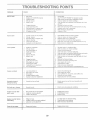
TROUBL£S
PROBLEM
CAUSE
Will P,ot start
8
7,
8.
9.
i0.
Clogged _uel ta_k.
Loose spark p_ug wire
Bad spai_k p!ug or improper gap.
Carburetor out of adjustment
Oi_ soaked air filter
6.
Fi!l fuel tank.
See "TO START ENGINE" in Operation section.
Wait several minutes before attempting to start.
Clean or replace air cieaner cartridge.
Drain fuel tank and carburetoL and refill tank with fresh
gasoline.
Remove fuel _ar_kand elearL
7.
8.
9.
t0.
Make sure spark pkJg wire is seated properly on plug.
Replace spark plug or adjust gap:
Make necessary adjustments.
Replace air Iitter.
[fi_ardto start
t.
2.
3.
4.
5,
6.
ThrottIe control r_ot set properly.
Dirtyair cbaner.
Bad spark plug or improper gap.
Stale or dirty Iuel.
L.oos÷ spark plug wi_e.
Carburetor out of adjustment.
t_
2.
3.
4,
5.
6.
Place throttle control in "FAST" position.
Cban or repIace air cieaner cad_#dge_
Replace spark plur:_or ad}ust gap.
D_ain fue_ ta_k and refill with flesh gasoline.
Make sure spark p!ug wire is seated praperly on piug.
Make necessary adjustments.
Loss
1
2.
3.
4
5.
Engine is overloaded.
Dirty air cleaner.
Low oil level/dirty oil
Fauity spark ptug.
Oil in faeI.
6.
7
Stale or dirty fuel.
Water in fuel.
1.
2.
3
4.
5.
6.
7.
Set depth stake for shallower tilting.
Cban or rep!ac_ air cleaner cartridge.
Check oil level/change oil:
Clean and r_gap or change spark plugo
Drain and clean fuel _ank and refill, and clean carburetor.
Drain fuel tank and refifi with fresh gasoline.
Drain Iue! tank and carburetor, and refill tank with fresh
gasoline.
Remove fuel tank and clean.
of po_'_er
i.
Out of fuel.
2.
3.
4.
5.
Engine not "CHOKED"
Engine flooded.
Dirty air cieaner.
Water in flJet
CORRKCTtON
8.
9.
I0.
11.
12.
o
I.
2.
3.
4.
5..
properly.
8.
CIogged fuel tank.
Spark plug wi_e toose_
Dirty engine air screen_
Dirty/clogged muffier.
Carburetor out of adjustment
Poor compression
9.
10.
11.
t2.
13.
Connect and tighten spark plug wire.
Clean engine air screen.
Cbanirepiace muffler.
Make necessary adjustments.
Coptact an authedzed sen/ice center!department
!
2
3.
4.
5.
Low oil leveYdi£y oil
Dirty engine air screen.
Dirty engine.
Partially plugged muffbr
_mproper carburetor adjustment.
1:
2_
3.
4.
5.
Check oil bvelichange oil.
Clean engine air screen
Clean cy!inder fins, air screen, and muffler area.
Remove and clean muffler.
i_jus_carburetor
to richer posiLion.
I
Ground too dry and hard.
1
Moisten ground or wait for more favorable
conditions.
Soil bails up or cla_ps
1.
Graund toe wet.
1.
Wait for more faverable
Engine
1.
2.
3.
Drive control bar is not engaged_
Vobelt not correctly adjusted.
V..belt is off pui!ey(s).
I.
2.
3_
Engage dnve control
Inspect/adjust Wbelt.
Inspect Vo.belt.
t.
2.
3.
Tilling too deep.
ThroLtle control not properly adjusted.
Carburetor out of adiustment.
i_
2.
3.
Set depth stake for shallower tilling.
Check throttle control setting.
Make necessary adiustments.
1.
Shear pin(s) broken.
!.
Replace shear pin(s).
Engine
overheats
Excessive
difficult
won_[[
boanoe/
ha£d_ir_g
r_ns b_t tiller
move
Engine runs but
when ti_Hn9
Rabors
Tines will not rotate
20
seil conditions.
soil
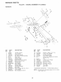
REPAMR PARTS
T LLER
o MODEL NUMBER
917o295652
HANDLES
\
\
2
\,
t5
/
22
21
23
\
\
\
\
KEY
NO.
PART
NO.
t
2
3
4
5
6
7
8
9
10
11
12
13
14
15
16
!7
t8
148583
141406
110673X
127254X
6712J
t37119
1!064tX
71 t91008
72010520
t10646X
STD624003
81328
11074tX
1093!3X
110702X
STD5337!0
109229X
STD541437
KEY
NOo
DESCRiPTiON
Throttle, Control
Grip, Handle
Grommet, Handle
Bar, Drive Controt Assembly
Cap, Vinyl
Panel, Controt
Bushing, Split
* Screw, Pan Head #10_24
* Bolt, 5/16d8 x 2o.1/2
Handle, Grip
* Clip, Hairpin
Bolt, Shoutder
Handle, Shift
Gromrnet0 Rubber
Rod, Shift
* Bolt, Carriage 3/8o16 x t Gr. 5
Lock, Handle
* Nut, Centedock 3/8-!6
PART
NO.
19
20
21
22
23
19131611
! 09228X
150258
I21 !45X
8677'7
24
25
26
27
28
29
30
31
9484R
73970500
110675X
STD54!025
STD551 !25
STD541462
104164X
! 50696
DESCRiPTiON
Washer 13/32 x 1 x 11 Ga.
Lever, Lock, Handle
Handle, Assemble
Clip, Plastic, Cable
Screw, Hex, Washer Hd, Slotted
#!0-24 x !/2
Ctip
Locknut, Hex, Ftange
Clutch, Cable
* Nut, Hex I/4_20
* Washer, Lock 1/4
* Nut_ Keps #!0-24
Tie, Cable
Bolt, Pivot
* STANDARD HARDWARE
NOTE:
2t
31
.... PURCHASE LOCALLY
All component dimensions
I inch = 25.4 mm
given in U.S. inches.
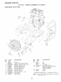
REPAMR PARTS
TWLLER -° MODEL
MAINFRAME,
LE_
NUMBER
9i7.295652
SIDE
9
10
8
39
,p
5
42
37
38
16
41
17
21
20
i9
3O
28
KEY
NO.
1
2
3
4.
5
6
7
8
9
10
11
12
!3
14
t5
16
17
!9
20
21
22
23
24
25
26
27
28
PART
NO.
STD541431
STD55ii37
STD541037
74930568
STD571810
1101!1X
STD532505
8700J
86777
3
27
DESCRIPTION
Nut, Keps 5/16q8
* Washer, Lock 3/8
* Nut, Hex 3/8q 6
Bolt, Flex 5/t6-18 x 4ol/4
* Pin, Roll
Lever, Shift
* Bolt, Carriage 1/4_20 x !/2 Gr. 5
Plate, Shift Indicator
Screw, Hex, Washer Head, Slotted
#10-.24 x 1/2
9484R
Clip
STD551 t25 * Washer, Lock 1/4
STD541 O25 * Nut, Hex 1/4-20
23230506
* Screw, Set, 5/18ot8 x 3/8
120938X
Spacer, Split 0.327 x 0.42 x 2.68
STD55103'1 *Washer 1!/32 x 11/16 x 16 Ga.
145! 02
Sheave, Transmission
STD541031
* Nut, Hex 5/16-18
12000028
Ring, Retainer
! 10653X
Guard, Pinch Point
145216
Spacer, Split 0.327 x 0.42 x 1.688
1O4214X
Nut, Cap 5/16-18
5015J
Tire
128952
Rim
795R
Tire Valve
126875X
Rivet, Drilled
STD624003
* Clip, Hairpin
131159X459
Guard, Belt
132801
Belt, V
104679X
Pulley, Idler
23
\
24
25
KEY
NO,
PART
NO.
29
30
31
32
33
34
35
36
37
38
39
4O
41
42
12000032
10561!X
102384X
t0214tX
STD523710
102383X
74760532
102331X
130812
145822
140062
7380O400
19111610
151004
DESCRIPTION
Ring, Klip
Bracket, Idler
Bolt, Hex 5/16-!6 x 12
Shaft, Idler Arm
* Bolt, Hex 3/8o!6 x 1
Counterweight, L.H.
Bolt, Hex 5/16-18 x 2
Bracket, Reinforcement, L.H.
Sheave, Engine
Stud, Guard Belt
Cap, Plunger
Nut, Lock w/Insert 1/4-20
Washer 11/32 x 1 x 10 Ga.
Spacer
*STANDARD HARDWARE
NOTE:
22
_-o PURCHASE LOCALLY
Att component dimensions
1 inch = 25.4 mm
given in U.S. inches.
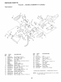
REPAIR PARTS
TILLER
MAINFRAME,
o o MODEL
NUMBER
917o295652
RIGHT SIDE
17
16
/
II
3
KEY
NO.
1
2
3
4
5
6
7
8
9
10
!1
12
PART
NO.
146934
73970500
STD55103t
74760512
! 02332X
74760532
t02173X
STD55t137
STD541037
74760524
STD624003
126875X
KEY
PART
NO.
NO,
13 50t5J
128952
795R
14 STD54t431
15 146153
D_SCRIPT[ON
Bumper
Locknut, He\, Flange 5116-18
* Washer 1t/32 x 11/16 x 16 Ga.
Bolt, Hex 5/16o18 x 3/4
Bracket, Reinforcement
Bolt, Hex 5/16-18 x 2
CounterWeight, R.H.
* Washer, Lock 3/8
* Nut, Rex 3/8-16
Bolt, Hex 5/16-18 x !-1/2
* Clip, Hairpin
Rivet, Drilled
t6
17
221535
94906
DESCRIPTION
Tire
Rim
Tire Valve
* Nut, Keps 5/16-18
Engine, Briggs & Stratton(IP)
Model No. 133402,
Type No. 0083-01
Ctamp
Screw
* STANDARD HARDWARE
NOTE:
23
: - PURCHASE
All component dimensions
I inch = 25.4 mm
LOCALLY
given in U.S.inches.
REPAMR PARTS
TILLER
o o MODEL
NUMBER
917.295652
TRANSMISSION
25
25
5
°44
18
48
18
KEY
NO.
KEY
PART
NOo
NO.
1 150697
2
150698
3
4
5
6
7
8
9
10
1!
12
13
14
15
16
18
19
20
10621tX
5020J
1370H
137335
145101
4895H
102136X
7392M
100371K
106160X
142145
8353J
12000039
140525
4358J
12000040
102114X
21
22
23
24
25
27
102115X
6803J
10211tX
STD551143
STD541143
143009
DESCR_PTION
Transmission Assembly
0ncludes Key Nos. 2°.52)
Gearcase, L.H. w/Bearing
(hcludes Key No. 4)
Gasket, Gearcase
Bearing, Needle
Washer, Thrust 5/8 x 1.t0 x t/32
Pinion, input
Shaft, Input
Bearing, Needle
Washer, Seal
Ball, Steet
Spring, Shift, Fork
O-Ring
Arm, Shift
Fork, Shift
Ring, Klip
Shaft, Shift
Washer
Ring, Klip
Gear, Assembly, Reverse idler
(Includes Key Nos. 2t and 22)
Gear, Reverse Idler
Bearing, Needle
Shaft, Reverse idler
* Washer, Lock 7/16
* Nut, Hex 7/16o20
Bearing, Shaft, Ground Ddve L.H.
PART
NO.
28
29
30
3t
32
33
34
35
36
106390X
102134X
150737
143008
.106388X
102t21X
t02112X
102101X
137300
37
38
39
40
41
42
43
44
45
46
47
48
4422J
137301
t05345X
105346X
8358J
4220R
t06146X
9672R.
102144X
140576
7393R
150700
49
50
51
52
53
--
132688
t06147X
17720408
73220500
122204X
6066J
DESCRIPTION
Spacer 0.765 x 1.125 x t.23
Chain #35-50 Pitch
Ground Shaft Assembly
Bearing, Shaft, Ground Drive R.H.
Spacer 0.70 x ! .00 x 1.!50
Sprocket and Gear Assembly
Shaft, Reduction (2rid)
Screw, Whiz, Lock 5/16o18 x 3-I/2
Sprocket Assembly w/Bearing
(Includes Key Nos. 37 and 38)
Bearing, Needle
Sprocket, Tine
Gear, Cluster, Red 1st & 2nd
Gear, Reverse
Shaft, Reduction (1 st)
Washer, Thrust
Spacer 1.01 x !'.75 x 0.760
Cup, Formed
Ring, Spiral
Seat, Ring, Rubber
Seal, Oil
Gearcase, R.H. w/Bearing
(Includes Key No. 8)
Shaft, Tine
Chain, Roller #50-50 Pitch
Screw t/4_20 x 1/2
Nut, Hex 5/16-18
Bearing Kit, Tine Shaft
Grease, Ptastilube #1
* STANDARD HARDWARE
NOTE:
24
- - PURCHASE LOCALLY
All component dimensions
1 inch = 25.4 mm
given in U.S. inches.
REPAIR PARTS
TILLER
-- MODEL NUMBER
917o295652
TINE SHIELD
5
7
8
/
5
°V
29
15
!9
21
/
KEY
NO.
1
2
3
4
5
6
7
8
9
10
11
!2
13
14
15
16
17
!8
PART
NO.
98000129
104086X459
8393J
12000036
STD533107
8394J
8392J
109230X
124289X459
STD5331 I0
STD54!031
STD55t131
72110510
124311X
!04101X459
STD541025
STD551125
STD532512
DESCRIPTION
Nut, Flange 5t16-18
Shietd, Side, Outer h Ho
Pin, Stake, Depth
Ring, KNp
* Bolt, Carriage 5/16-18 x 3/4 Gr 5
Spring
Bracket, Latch
Spring, Depth Stake
Shield, Tine
* Bolt, Carriage 5/!6-18 x 1 Gr. 5
*Nut, Hex 5/!6-!8
*Washer, Lock 5/16
Bolt, Carriage 5/t6-18 x 1-1/4
Bracket, Shield Tine
Shield, Side, Outer R.H.
* Nut, Hex 1/4o20
*Washer, Lock 1/4.
* Bolt, Carriage 1/4-20 x 1ol/4 Gr. 5
KEY
NO.
PART
NO.
19
20
2t
22
23
24
25
26
27
28
29
30
t 02701 X
STD541037
102!56X
74930632
4440J
72140404
67!2J
109227X
!02695X459
120588X
124309X459
73970500
DESCRIPTION
G rip
: Nut, Hex 3/8-16
Stake, Depth
Bolt, Hex 3/8-16 x 2
Hinge
* Bolt, Carriage 1/4-20 x 1/4
Cap, Vinyl
Pad, Idler
Shield, Leveling
Pin, Hinge
Shield, Side
Locknut, Hex, Flange
* STANDARD HARDWARE - -. PURCHASE LOCALLY
NOTE:
25
All component dimensions given in UoS. inches.
! inch = 25A mm
REPAIR PARTS
TroLLER o o MODEL NUMBER
917.295652
TJNE ASSEMBLY
3
3
8
9
11
9
9
KEY
NO,
1
2
3
4
5
6
7
PART
NO.
4459J
132673
6554J
STD624008
t32727
73610600
STD551137
KEY
PART
DESCRiPTiON
NO.
NO.
8 74610616
Bolt, Hex 3/8--24 x 1
9 4460J
Tine, Outer, R.H.
10 132728
Assembly, Hub and Plate, R.H.
11 6555J
Tine, Inner, R.H.
* STANDARD HARDWARE --PURCHASE LOCALLY
DESCRIPTION
Tine, Outer, L.H.
Pin, Shear
Tine, Inner, L.H°
* Clip, Hairpin
Assembly, Hub and Plate, L.H.
Nut, Hex 3/8-24
* Washer, Lock 3/8
NOTE:
26
Allcomponent dimensions given inU.S, inches.
I inch= 25.4 mm
REPAIR PARTS
TILLER
_ o MODEL
NUMBER
917o2£5652
DECALS
4
2
3
\
8
7
\
10
\
KEY
NO.
1
2
3
4
5
6
7
8
10
-_
o_
PART
NO.
152399
138813
152397
152400
137538
120431X
102180X
147592
120075X
153224
153225
DESCRIPTION
Decal, Logo
Decal, Logo
Decal, Logo
Decal, Description
Decal, Caution, Drive Control
Decal, Hand Placement
Decal, Shift indicator
Decal, Operation and Lubrication
Decal, Warning, Rotating Tines
Manuam,Owner's (English)
Manual, Owner's (Spanish)
27
R
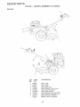
AIR PARTS
TILLER
ENGINE,
o o MODEL
BR_GGS & STRATTON
NUMBER
o - _IODEL
917o295652
NUMBER
333402, TYPE NO. 0083.-01
308
13A
5
306
28
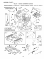
REPAIR PARTS
TILLER
ENGINE,
o _ MODEL
BRmGGS & STRATTON
NUMBER
9!7.295652
o o MODEL NUMBER
133402, TYPE NO. 0083o01
26
12
27
4®
220
3
219 _
36 _
35
20
40
32
REQUIRES SPEOIAL TOOLS
TO tNS°_ALL SEE REPAIR
_NS"TRUC_°_ON_ANUALo
24
57
1016
461
65
55
29
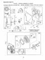
REPAIR PARTS
TILLER
ENGmNE, BR]GGS
o o MODEL
& STRATTON
NUMBER
917.295652
o ° MODEL NUMBER
133402, TYPE NO. 0083-01
125
®
124
%
@ G34
634A
137_
95
3
2O
52
J_J
883
[
_)
104
137
O
116
(_
634
634A
137
977 OARBfJRIETOR
GASKET
SET
134
(5
127
SET
@
116
O
[
30
358 GASKET
121 CARBURETOR
t(IT
REPAtR PARTS
T_LLER _ o MODEL
ENGMNE_ BRHGGS & STRATTON
NUMBER
917o295652
o o MODEL NUMBER
642
133402_ TYPE NOo 0083o01
832
535
445
346
851
!1
335
23
3O4
\
_305
73
332
@
31
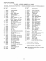
REPAIR PARTS
TILLER - ° MODEL NUMBER
ENGINE, BR GGS
KEY PART
NO. NO.
1
2
3
5
7
8
9
10
1t
12
495133
399268
2998!9
214040
272157
495774
27549
94621
66578
270080
270125
270126
13 94221
13A 94167
14 94679
15 94387
15A 93448
16
18
19
20
21
21A
22
22A
23
24
25
26
27
28
29
3O
32
33
34
4.92088
94388
494044
495660
294606
66768
399195
94682
94666
399673
222698
393819
393820
393821
393822
399067
399014
399015
399016
26026
298909
298908
299430
390459
221890
94745
211119
261044
& STRATTON
917o295652
o - MODEL NUMBER
KEY PART
NO, NO.
DESCRIPTION
Cylinder Assembly
Bushing
*Seal, Oil
Head, Cylinder
*Gasket, Cylinder Head
Breather Assembly
*Gasket, Breather
Screw, Breather Mounting
Grommet
*Gasket, Crankcase, .015" Thick
(Standard)
* Gasket, Crankcase, .005" Thick
* Gasket, Crankcase, .009" Thick
Screw, Cylinder Head 2-5/16
Stud, Cylinder Head
Screw, Cylinder Head 2-15/32
Plug, Oil Drain, 1/4" Standard,
Square Head
P!,,,_ Oi! Drain, !/4" Standard,
Flush, Hex Socket Head
Crankshaft
Crankshaft Gear Key
Cover, Crankcase
Bushing
Seal, Oil
Plug, Oi! Fill
Plug, Oil Fi!l (For High Oil Filt Hole)
Screw, Crankcase Cover Mounting
Stud, Hex Head,
Crankcase Cover Mounting
Flywhee!
Key, Flywheel
Piston Assembly, Standard Size
Piston Assembly, .010" Oversize
Piston Assembly, .020" Oversize
Piston Assembly, .030" Oversize
Ring Set, Standard Size
Ring Set, .010" Oversize
Ring Set, .020" Oversize
Ring Set, o030"Oversize
Lock, Piston Pin
Pin, Piston, Standard Size
Pin, Piston, .005" Oversize
Rod, Connecting
Rod, Connecting, .020" Undersize
Crankpin Bore
Dipper, Connecting Rod
Screw, Connecting Rod
Valve, Exhaust
Valve, Intake
35
36
37
40
45
46
5!
52
53
54
55
56
57
58
59
60
65
69
69A
73
75
95
98
98A
104
108
t 11
116
118
t21
124
125
127
t30
131
133
134
137
*
**
***
260552
26478
222443
93312
260642
212733
272295
272585
94705
94706
494846
493824
262594
280406
396892
393152
94686
280973
224322
224632
495659
94098
398185
493280
224783
262820
493765
493762
94681
495652
223470
493556
398187
398188
133402, TYPE NO. 0083o01
DESCRIPTBON
Spring, Intake Valve
Spring, Exhaust Valve
Guard, Flywheel
Retainer, Spring
Tappet, Valve
Gear, Cam
* Gasket, Carburetor
* Gasket, Intake Port
Screw, Adapter Mounting
Screw, Hex Head
Housing, Rewind Starter
Pulley, Starter
Spring, Rewind Starter
Rope, Starter
(Cut to Required Length)
Insert, Starter Handle
Handle, Rewind Starter
Screw, Starter Mounting
Washer, Rewind Starter
Washer, Rewind Starter
Screen, Rotating .
Washer Kit
Screw, Round Head
Screw, Idle Adjusting
Screw Assembly,
Speed Adjustment
** Pin, Hinge (Sold in Kit Only)
Valve, Choke
Spring, Lever
Gasket, Sealing (Sold in Kit Only)
Valve and Spring, Needle
Carburetor Kit
Screw, Hex Washer Head
Carburetor
** Plug, Welch
Valve, Throttle
Shaft, Throttle
Float, Carburetor
** Valve, Inlet (Includes Seat)
** Gasket, Bowl (Sold in Kit Only)
Included in Gasket Set (495661)
Included in Carburetor Kit (493762)
Included in Carburetor Kit (493762), and
Carburetor Gasket Set (490937)
NOTE: All component dimensions given in U.S. inches
1 inch = 25.4 mm
32
REPAIR PARTS
T LLER
ENGtNE
BRIGGS
KEY PART
NOo NO.
141
159
163
164
165
182
184
185
187
187A
188
200
20!
209
219
220
222
227
230
232
284
300
304
306
30Z
308
332
333
335
337
495651
280871
272537
281247
94692
224669
93559
940t0
393815
4952!8
94357
223886
262865
262283
494845
221551
494899
494906
94742
260585
94620
494562
497018
©
2L4820
94680
224740
92284
397358
93414
802592
346
347
356
356A
358
363
383
'9
42.
445
455
456
459
461
515
524
528
535
552
562
592
93705
493521
495135
4.95118
495661
19069
89838
281190
494511
224250
224321
492833
262626
262625
271485
231818
495246
231079
92613
231082
o o MODEL NUMBER
& STRATTON
°
917o295652
MODEL NUMBER
KEY PART
NO. NO.
DESCRIPTION
601
Shaft, Choke
Support, Air Cleaner
* Gasket, Air Cleaner
Manifold, Intake
Nut, Wing
Bracket, Fuel Tank
Screw, Hex Head
Nut, Hex
Line, Fuel (11" Long, Cut to Suit)
Line, Fuel, Molded
Screw, Hex Head
Guide, Air
Link
Spring, Governor
Gear, Governor
Washer, Thrust
Bracket, Controt
Lever Assembly, Governor
Washer, Governor Lever
Spring, Link
Screw, Hex Head
Muffler, Exhaust
Housing, Blower
Shield, Cylinder
Screw, Rex Head, Cylinder Shield
Cover, Cylinder Head
Nut, FIywheei
Armature, Magneto
Screw, Armature
Plug, Spark
(I_7/8" High, 48ram, Resistor Type)
Screw, Hex Head, Sems
Switch, Stop
Wire, Stop (Armature to Switch)
Wire, Stop (Stop Switch to Ground
Gasket Set
Puller, Flywheel
Wrench, Spark Plug
Cover, Spark Plug
Filter, Air
Cup, Flywheet
Retainer, Spring
Pawt, Ratchet
Pin, Starter
Spring, Torsion
* Seal, Oit Fill
Tube, Breather
Filter, Air
' Bushing, Governor Crank
Bolt, Governor Lever
Nut, Rex
608
611
613
614.
616
634
634A
635
642
663
676
741
832
843
85t
864869
870
871
883
955
957
958
966
969
97!
972
975
977
978
979
982
984
t016
10t9
1058
*
**
***
93053
93807
494782
494451
94729
93306
495243
°- o
°o66538
281188
93343
495074
262992
Uses:
494903
280149
221798
494904.
2t !787
2ti436
262001
63709
272309
495650
495981
493988
494539
4.94902
94.!20
94727
495345
493640
490937
271736
494807
94658
224746
224278
495861
272528
TYPE NOo 0083o01
DESCRIPT_ON
Clamp,. Hose, Green
Clamp, Hose, Black
Starter, Rewind
Connector, Fue_ Line
Screw, Sems
Pin, Cotter
Crank, Governor
*** Sea!, Shaft (Sold in Kit Only)
*** Seal, Choke Shaft (Sold in Kit Only)
Elbow, Spark Ptug
Cover, Air Cleaner
Screw, Sems
Deflector Assembly
Gear, Timing
94388
Key, Woodruff
Guard, Muffler
Sleeve, L.ever
Terminal, Cable
Flange, Muffler
Seat, Intake Valve
Seat, Exhaust Valve, Cobalite®
Guide, Exhaust Valve
Guide, Intake Valve
* Gasket, Exhaust
Screw, Fuel Bowt
Screw, Fue! Bowl High A!titude
Cap, FuelTank
Valve, bhut.-Off
Base, Air Cleaner
Screw, Hex Head
Screw, Hex Head
Tank, Fuet
Bowl, Float
Gasket Set, Carburetor
* Gasket Cover
Cover, Oil Gard®
Screw, Oil Gard® Cover
Bracket, Indicator Light
Cover, Rewind Starter
Label Kit
Owner's Manual
Included in Gasket Set (495661)
_nctuded in Carburetor Kit (493762)
_ncluded in Carburetor Kit (493762), and
Carburetor Gasket Set (490937)
NOTE:
33
133402
Al! component dimensions given in U..S. inches
1 inch = 25°4 mm
34
$
35
£
®
5.0 HP
17 iNCH Tt E Wi
A TmNE TILLER WiTH
TINES
COUNTER ROTAT!
MODEL NO.
917.295652
Each tiller has its own model number,. Each engine has its own model
number.
The model number for your tiller will be found on a plate attached to the
top of the transmission.
The model number for your engine will be found on the blower housing of
the engine.
JF YOU NEED
REPAIR SERVICE
OR PARTS:
FOR REPAIR SERVICE, CALL
THIS TOLL FREE NUMBER:
I_800o4oREPAmR
(1o800o473o7247)
All pa_ts listed hereff3 may be ordered from any Sears Roebuck and Co.
Service Center/Department and most Retail Stores. "
WHEN ORDERING REPAIR PARTS, ALWAYS
iNG MNFORMATION:
G_VE THE FOLLOW-
PRODUCT o REAR TgNE TILLER
o MODEL NUMBER - 917.295652
ENGINE MODEL NUMBER o 133402, TYPE NUMBER 0083-01
PART NUMBER
FOR REPLACEMENT PARTS
INFORMATION AND
ORDERING, CALL THIS
TOLL FREE NUMBER:
loS00oFON°PART
(! °800o366-7278)
o PART DESCRIPTION
Your Sears merchandise has added value when you consider Sears has
service units nationwide staffed with Sears trained technicians.., professional technicians specifically trained to insure that we meet our pledge
to you, we service what we sell.
o__
E
Sears,
153224 t.24.96
TR
Roebuck
and Co., Noffman
Estates,
IL 60179 U°S°Ao
PRINTED 1NTHE U.S.A.