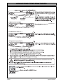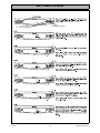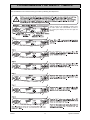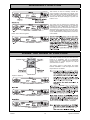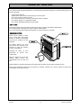
1
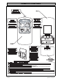
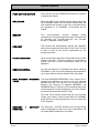
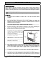
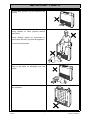
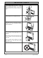
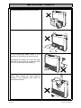
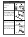
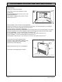
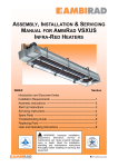
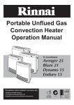
Portable Unflued Gas
Convection Heaters
With Electric Boost
Operation Manual
To Suit Models
Avenger 25 Plus
Capella 18 Plus
This appliance shall be installed in accordance with:
• Manufacturer’s Installation Instructions
• Current AS/NZS 3000 & AS/NZS 5601
• Local Regulations and Municipal Building Codes
This appliance must be installed, serviced and repaired by an Authorised Person.
N10378
This page intentionally blank.
Rinnai
i
Operation Manual
TABLE OF CONTENTS
ABOUT YOUR NEW AVENGER/CAPELLA PLUS ....................................................2
CONTROL PANEL LAYOUT ......................................................................................3
REMOTE CONTROL ...................................................................................................4
FEATURES ..................................................................................................................5
IMPORTANT POINTS .................................................................................................6
CUSTOMER OPERATING INSTRUCTIONS ............................................................11
HOW TO OPERATE THE HEATER ..........................................................................12
ADJUSTING TEMPERATURES................................................................................13
HEATER MODES & FUNCTIONS.............................................................................14
SETTING HEATER MODES......................................................................................15
SETTING CLOCK ......................................................................................................16
PROGRAMMING THE ON/OFF TIMERS..................................................................17
OPERATING THE ON/OFF TIMERS ........................................................................18
PRE-HEAT .................................................................................................................18
OVERRIDE FUNCTION .............................................................................................19
USING THE REMOTE CONTROL ............................................................................19
CHILD LOCK .............................................................................................................20
SAFETY DEVICES ....................................................................................................20
CARE OF HEATER ...................................................................................................21
TROUBLE SHOOTING..............................................................................................22
ERROR CODES ........................................................................................................23
SPECIFICATIONS .....................................................................................................24
CONTACT INFORMATION .......................................................................................26
Rinnai
1
Operation Manual
ABOUT YOUR NEW AVENGER/CAPELLA PLUS
STANDBY/ON BUTTON
Rinnai
2
Operation Manual
STA N D B Y/ ON
S TA N D B Y / ON button
CONTROL PANEL LAYOUT
Rinnai
3
Operation Manual
REMOTE CONTROL
STANDBY BUTTON
Timer mode.
STANDBY button will cancel any future timer
operations, these will have to be reset manually.
Rinnai
4
Operation Manual
FEATURES
PUSH BUTTON IGNITION
Only one touch of the STANDBY/ON switch is required
to operate the heater.
CHILD LOCK
When the Child Lock is activated all controls other than
the STANDBY switch will be locked. Deactivating the
lock releases the controls. If the lock is activated when
the appliance is in STANDBY, all functions will be
locked.
MEMORY
The
micro-computer
records
selected
preset
temperatures, the times programmed into Timers as well
as operating the Economy/Auto-Off and Pre-heat
modes, to maintain comfort levels.
PRE-HEAT
This function will automatically operate the appliance
before the programmed start time of the Timer, in order
to heat a room to the pre-set temperature by the
programmed time.
FILTER INDICATOR
When the fan filters become covered with dust, the filter
indicator will flash. The filters should be vacuumed at
regular intervals to avoid unnecessary strain on the
appliance.
REMOTE CONTROL
For the convenience of operating the heater between
STANDBY or ON, as well as adjusting the temperature
up or down while at a short distance from the heater.
DUAL WEEKDAY / WEEKEND
TIMER
The Dual WEEKDAY/WEEKEND Timer allows you to
program the appliance to come on for two separate
periods each day, one period in the morning and one
period in the evening, on separate WEEKDAY and
WEEKEND timers. The built in Pre-heat Mode brings the
room temperature to the temperature you have selected,
by the time programmed into the Timer.
The Dual Timer feature means that you can "Set and
Forget" your heater. It will turn itself ON or to STANDBY
at the times you have programmed until you cancel the
Timer program.
ECONOMY
FUNCTION
Rinnai
/
AUTO-OFF
The Economy / Auto-Off functions are energy saving
feature designed to control the room temperature and
are automatically selected in all modes.
5
Operation Manual
IMPORTANT POINTS
Unpacking Appliance:
Check for damage. If the heater is damaged, contact your supplier for advice. Before installing the
appliance, check it is labelled for the correct gas type (see label on rear of heater). Refer to local gas
authority for confirmation of gas type if you are in doubt. The following items should also be included in
the carton: Customers Operation Information, Remote Control, Remote Control Caddy and Batteries.
DO NOT modify this appliance.
WARNING
Servicing shall be carried out ONLY by authorised personnel.
IMPORTANT
1.
The appliance must be installed in accordance with the local gas and electrical authority
regulations.
2.
For information on gas consumption, see data plate on the appliance.
3.
When using this appliance, ensure that the room is correctly ventilated. Check AS5601 (Gas
Installations) or the local gas authority for information on ventilation requirements, or refer to the
warning label located on the appliance.
4.
DO NOT connect this appliance to the gas supply to heat a bedroom. It may be connected
to the electric supply for heating a bedroom in ‘ELECTRIC’ mode only.
5.
DO NOT use this heater in the immediate surroundings of a bath, shower, swimming pool,
toilet or sauna. The appliance must not be used to heat any of these areas.
6.
DO NOT connect to an LPG Gas cylinder indoors.
7.
This appliance must not be installed where
curtains or other combustible materials could
come into contact with it. In some cases
curtains may need restraining.
8.
This appliance is not designed to be built in.
Not intended for fireplace insert.
9.
Heater must not be located below a power
socket-outlet.
10.
If you move house, check the gas type in the
area where you are moving to.
50mm
50mm
SET
ON/ OFF
50mm
50mm
750mm
11.
The local gas and electrical authorities will be
able to advise on local regulations.
12.
Heat emanating from the front of this appliance may over time affect the appearance of some
materials used for flooring such as carpet, vinyl, cork or timber. This effect may be amplified if the
air in the room contains cooking vapours or cigarette smoke. To avoid this possibility, it is
recommended that a mat be placed in front of the appliance, extending at least 750 mm in front
of it.
13.
The appliance is not intended for use by young children or infirm persons without supervision.
14.
Young children should be supervised to ensure they do not play with the appliance.
15.
If the supply cord or gas hose are damaged or require replacing, they must be replaced by the
manufacturer or the manufacturer's agent or similarly qualified person in order to avoid a hazard.
16.
The appliance weighs 21 kg. Exercise caution when lifting or moving.
Rinnai
6
The above diagram shows the clearances required
around this heater whilst in operation.
Operation Manual
IMPORTANT POINTS
Do not allow children to post articles in the
louvres.
The appliance is not intended for use by
young children or infirm persons without
supervision.
Young children should be supervised to
ensure they DO NOT play with the appliance.
Do not sit on this heater.
Do not allow children or elderly persons to
sleep in the warm air discharge from the
heater.
Do not cover or place articles on or against
this appliance.
Rinnai
7
Operation Manual
IMPORTANT POINTS
Do not operate/install this heater in areas
where painting is taking place, or in places
such as hairdressing salons, where there
may be fluff and dust, and where aerosols are
used.
Turn the heater on to STANDBY after use.
Keep heater away from flammable materials.
DO NOT use or store flammable materials
near this appliance.
Do not spray aerosols near this heater while it
is in the vicinity of this heater while it is in
operation.
Most aerosols contain butane gas which can
be a fire hazard if used near this heater when
it is in use.
Use of aerosols, paint, polishes etc. whilst
this heater is in use may also cause
unpleasant smells.
DO NOT modify this appliance.
Rinnai
8
Operation Manual
IMPORTANT POINTS
Do not place articles in front of the louvres.
Do not move the heater whilst it is turned on.
Do not unplug the heater while it is in
operation or while the fans are still cycling.
Unplugging the heater will cause the timer
and clock to stop, however programmed ON/
OFF times will remain in the memory.
Do not place containers of liquid on top of the
heater. Water spillage can cause extensive
damage to the appliance and create an
electrocution hazard.
Rinnai
9
Operation Manual
IMPORTANT POINTS
A dedicated 240v 10 Amp power point must
be used with this appliance.
Do not use power boards or double adaptors
to operate this appliance.
Heater must not be located below a power
socket-outlet.
Heat emanating from the front of this
appliance may over time affect the
appearance of some materials used for
flooring such as carpet, vinyl, cork or timber.
This effect may be amplified if the air in the
room contains cooking vapours or cigarette
smoke. To avoid this possibility, it is
recommended that a mat be placed in front of
the appliance, extending at least 750 mm in
front of it.
During peak operating periods the filters
should be cleaned weekly, however if the
“FILTER” warning indicator flashes in the
control panel display, turn off the appliance
immediately and clean filters before further
use.
When the heater is operated for the first time
or after long periods of non use a slight odour
may be emitted, this is normal.
However if odours persist switch of the
appliance and contact Rinnai.
Rinnai
10
Operation Manual
CUSTOMER OPERATING INSTRUCTIONS
INSTALLATION
Check room size and ventilation
This heater must not be installed in a room
smaller than:
The AVENGER 25Plus must not be in a room
smaller than 62.5 m3.
The CAPELLA 18Plus must not be in a room
smaller than 45.0 m3.
Height
HE
De
pt
h
AT
ER
Width
Fixed ventilation must conform to local regulations.
Number and position of vents is for illustrative purposes only. For more information on ventilation,
please refer to our Rinnai Web Site www.rinnai.com.au
DO NOT install in a bedroom or bathroom.
The bayonet plug on the factory fitted flexible hose simply plugs into your bayonet fitting. The control
panel is located on the top of the appliance, basic controls are also located on the remote control.
For the AVENGER - H x W x D must equal or exceed 62.5 m3 .
For example: if room size is L 5.2 m x W 5.0 m x H 2.4 m the volume will be 62.4 m3
For the CAPELLA - H x W x D must equal or exceed 45.0 m3 .
For example: if room size is L 4.5 m x W 4.2 m x H 2.4 m the volume will be 45.4 m3
This heater must not be installed where
curtains or other combustible materials could
come into contact with it. In some cases
curtains may need restraining.
50mm
50mm
SET
ON/ OFF
Other clearances are shown in the diagram.
50mm
50mm
This heater is not designed to be built in.
750mm
The above diagram shows the clearances required
around this heater whilst in operation.
Rinnai
11
Operation Manual
HOW TO OPERATE THE HEATER
STANDBY/ON
STANDBY/ON Button
STANDBY/ON
''STANDBY/ON'' button once.
''STANDBY/ON''
15
12
13
To return the heater to STANDBY
STANDBY/ON
To return the heater to STANDBY while it is in
operation press the ''STANDBY/ON'' button once.
''STANDBY/ON'' button twice to restart.
heaters ''STANDBY/ON'' button
The ''STANDBY'' and ''ON'' buttons located on the remote control can also be used to operate the
appliance.
Remote control STANDBY and ON Buttons
Rinnai
12
Operation Manual
ADJUSTING TEMPERATURES
STANDBY/ON
''STANDBY/ON'' button
STANDBY/ON Button
''STANDBY/ON''
STANDBY/ON
button once.
STANDBY/ON
STANDBY/ON
Rinnai
13
Operation Manual
HEATER MODES & FUNCTIONS
Your appliance has several "MODE" settings to choose from. The factory default setting is "GAS". For your
convenience in normal operation the appliance’s memory will select the “MODE” that was last used.
COMFORT AND ECONOMY
As a room is warmed, the walls and ceilings are also warmed, making one feel a little warmer than when the ceilings
and walls were cold, even though the room temperature is the same. The Economy (ECON) function prevents
discomfort from overheating and saves energy.
“GAS” MODE
When operating in this mode, the appliance will heat the room using gas convection. Gas combustion in this mode
is continuous and will adjust automatically to maintain the “SET” temperature.
"GAS ECON" MODE
When operating in this mode, the appliance will heat the room using gas convection. Once the “SET” Temperature
has been maintained for a period of 30 minutes, the comfort control system will progressively lower the “SET”
temperature by 2°C over a period of 60 minutes. When ‘ECON’ only is selected, gas combustion is continuous and
will adjust automatically to maintain the “SET” temperature minus 2°C.
Note: that during operation in this mode the “CURR” room temperature displayed may be lower than the “SET”
temperature, however this is normal.
"GAS ECON AUTO OFF" MODE
When operating in this mode, the appliance will heat the room using gas convection. Once the “SET” temperature
has been maintained for a period of 30 minutes, the comfort control system will progressively lower the “SET”
temperature by 2°C over a period of 60 minutes. When ‘ECON’ & ‘AUTO OFF’ are selected, gas combustion will
start and stop automatically to maintain the “SET” temperature minus 2°C.
Note: that during operation in this mode the “CURR” room temperature displayed may be lower than the “SET”
temperature, however this is normal.
“GAS ELECTRIC” MODE
When operating in this mode, the appliance will heat the room using Gas convection or Gas and Electric convection.
Electric convection is used only when the room is cold and/or when the heat load is high. Gas combustion in this
mode is continuous and will adjust automatically whilst the electric convection is turned on and off to maintain the
“SET” temperature.
“GAS ECON ELECTRIC” MODE
When operating in this mode, the appliance will heat the room using Gas convection or Gas and Electric convection.
Electric convection is used only when the room is cold and/or when the heat load is high. Once the “SET”
temperature has been maintained for a period of 30 minutes, the comfort control system will progressively lower the
“SET” temperature by 2°C over a period of 60 minutes. When ‘ECON’ only is selected, gas combustion is continuous
and will adjust automatically to maintain the “SET” temperature minus 2°C.
Note: that during operation in this mode the “CURR” room temperature displayed may be lower than the “SET”
temperature, however this is normal.
“GAS ECON ELECTRIC AUTO OFF” MODE
When operating in this mode, the appliance will heat the room using Gas convection or Gas and Electric convection.
Electric convection is used only when the room is cold and/or when the heat load is high. Once the “SET”
temperature has been maintained for a period of 30 minutes, the comfort control system will progressively lower the
“SET” temperature by 2°C over a period of 60 minutes. When ‘ECON’ & ‘AUTO OFF’ are selected, gas combustion
will start and stop automatically to maintain the “SET” temperature minus 2°C.
Note: that during operation in this mode the “CURR” room temperature displayed may be lower than the “SET”
temperature, however this is normal.
“ELECTRIC” MODE
When operating in this mode, the appliance will heat the room using Electric convection. The Electric element will
switch on and off automatically to maintain the “SET” temperature.
Note: Electric convection will only operate when the “SET” temperate is at least 2°C higher than the “CURR”
temperature. Timer operation is disabled when the appliance is in the “ELECTRIC” only mode.
Rinnai
14
Operation Manual
SETTING HEATER MODES
Rinnai
15
Operation Manual
SETTING CLOCK
S TA N D B Y / O N
STANDBY condition.
STANDBY/ON Button
S TA N D B Y / O N
S TA N D B Y / O N
S TA N D B Y / O N
S TA N D B Y / O N
S TA N D B Y / O N
S TA N D B Y / O N
''STANDBY/ON'' Button
STANDBY
Rinnai
16
Operation Manual
PROGRAMMING THE ON/OFF TIMERS
Here we will learn how to set the Timer (s) function by following the steps below.
STANDBY/ON Button
STANDBY/ON
With the heater in the STANDBY condition press
the ''SET'' button until ''PROGRAM'' is shown in
the control panel display and the hour digits are
flashing.
STANDBY/ON
STANDBY/ON
STANDBY/ON
STANDBY/ON
STANDBY/ON
STANDBY/ON
Rinnai
17
Operation Manual
OPERATING THE ON/OFF TIMERS
Now that the timer (s) functions have been programmed they can operated as follows.
STANDBY/ON Button
STANDBY /O N
STANDBY /O N
STANDBY /O N
STANDBY /O N
STANDBY /O N
PRE-HEAT
This function operates automatically in conjunction with the Timers. When a Timer is selected, the heater may
operate anywhere within an hour prior to the programmed starting time of a Timer.
This function is called Pre-heat since it ensures the room
reaches the desired temperature by the time the Timer
programs On time. The room temperature is sensed one
hour before reaching Timers programmed ON time.
The temperature differential at the time of sensing the room
temperature combined with the data from previous
operation governs exactly how long before the programmed
ON time the micro-computer will operate the heater and
ignite the burner.
Rinnai
18
Operation Manual
OVERRIDE FUNCTION
STANDBY/ON
STANDBY/ON
Return to Set Timer Programs.
This function is used to manually override the
current operation of the heater. For example: if the
heater is between the finnishing and starting times
of a timer program and the Override button is
selected, then the heater will begin to operate and
heat the room.
The heater must be between the finnishing and
starting times of a timer program for the Override
to function to work, ''TIMER ON'' is shown in the
control display and the On/Combustion indicator is
illuminated Green (steady) when this is the case.
Press the ''OVERRIDE'' button once to turn heater
on, the heater Mode and Temperature controls are
now available.
STANDBY/ON
''STANDBY/ON''
USING THE REMOTE CONTROL
The remote control can only be used when the
heater is in STANDBY, ON or in OVERRIDE
modes. If the heater is between the finnishing and
starting times of a timer program the remote
control will have no effect.
STANDBY Button
The remote control is able switch the heater
between STANDBY or ON and adjust the heater
temperature UP or DOWN.
Heater in Stand by.
STANDBY/ON
STANDBY
STANDBY/ON
STANDBY/ON
the ''STANDBY''
button once will return the heater to STANDBY.
return the heater to STANDBY, then the
Rinnai
19
Operation Manual
CHILD LOCK
STANDBY/ON
STANDBY/ON Button
''TIMER''
to ''STANDBY''
to
''STANDBY''
''STANDBY''
STANDBY/ON
STANDBY/ON
SAFETY DEVICES
OVER HEAT SWITCH
When the heater gets too hot during operation (for example when the filters or air outlet louvers are blocked) this
device turns the gas and or electric heating element off automatically. Remove cause of overheat (clean filters) allow
heater to cool, then re-ignite.
FUSE
The electrical circuits are protected by a fuse. When the fuse blows, the heater will not operate at all. The fuse must
be replaced by an authorised person.
FLAME FAILURE DEVICE
This device automatically cuts off the gas supply to the heater in the event of a gas failure. To restore the gas supply
to the heater, turn it off, and then follow the ignition procedure.
OXYGEN DEPLETION SAFETY DEVICE
If the oxygen level in the room drops below a pre-set limit, this device cuts the gas supply to the heater. If the oxygen
depletion device operates, turn the heater off, ventilate the room, then follow the ignition procedure to re-light. Heater
will not re-light unit room is fully ventilated.
TILT SWITCH
If the heater is knocked over, the tilt switch will cut the gas supply and or the power to the electric heating element.
The fan keeps running. To restore the gas supply, stand the heater upright, turn it off then follow the ignition
procedure. The tilt switch may also operate if the heater is jolted or picked up whilst in operation.
POWER FAILURE
In the event of a power failure or power cut, the gas valves will automatically close. After the power is re-instated
the appliance must be operated manually.
Rinnai
20
Operation Manual
CARE OF HEATER
Your heater needs very little maintenance, but the following information will help you to keep it looking good, and
working efficiently.
Unplug before cleaning.
All parts of the heater can be cleaned using a soft, damp cloth.
Do not use solvents to clean any parts.
Do not spray aerosols in the vicinity of the heater whilst in operation.
Do not place articles on or against this heater.
Do not store flammable materials near this heater.
AIR FILTERS
Dusty filters reduce the air flow through the heater as well as reducing the heater's effectiveness.
Do not wait for filter warning lamp to come on before cleaning filters.
Do not use the heater with the filter warning lamp on, this may cause it to overheat.
REMOVING FILTERS
Filters require cleaning at least
once a week during the heating
season to prevent unnecessary
cut-out due to a build up of dust
particles.
For cleaning Filters 1 & 2, undo
and remove the retaining screw
(ensuring to store the retaining
screw in a safe place)
Carefully lift filters up
backwards to remove
locating tabs.
then
from
With the careful use of a vacuum
cleaner, gently remove any
contaminates such as dust and
lint.
Replace filters by carefully repositioning the location tabs and fasten in place with the retaining screw.
Filter 3 (the small filter) should be left in position for cleaning, carefully use a vacuum cleaner to remove any
contaminates such as dust and lint.
Rinnai
21
Operation Manual
TROUBLE SHOOTING
Please note: Service calls for general cleaning, maintenance and wear and tear are not necessarily covered under
the guarantee. Service calls of this nature may be chargeable.
SERVICE
Rinnai recommend that this appliance be serviced every 2 years.
If the power supply cord, gas supply hose or any other component of the heater is damaged, they must be replaced
by Rinnai or a suitably qualified person.
Any service or repair work should only be carried out by an authorized person.
Rinnai Australia has service and spare parts departments.
Fault Finding Procedure
If you are unsure about the way your heater is operating, contact Rinnai Australia, or your local agent.
Rinnai
22
Operation Manual
ERROR CODES
Your appliance has the ability to check its own operation continuously. If a fault occurs an Error Code will flash on
the digital display of the control panel. This assists with diagnosing the fault and may enable you to overcome a
problem without a service call. Please quote the Error Code displayed when enquiring about service.
Red (Flashing)
Heater Operational Error
(used in conjuction with Error Code)
STANDBY/ON
Maintenance Monitor
Error Code
STANDBY/ON switch ON
STANDBY/ON button
Switch the Heater to STANDBY and then ON again
Overheat (Electric heater)
Check gas supply is turned on, Switch the Heater to
STANDBY and then ON again. Service call if repeated.
Overheat
Thermocouple failed to read the prescribed temperatures
during the 1st eighty seconds of operation.
Check gas cylinder (LPG models only) and check air filters.
Thermocouple Temperature Error
STANDBY/ON Switch faulty
Switch the Heater to STANDBY and then ON again
* Make sure that the gas supply is on, also it is quite possible that there are pockets of air in the supply hose or in
the heater itself and these will need to be purged, if heater fails to ignite on initial attempt try 3 to 4 more times,
however if the heater ignition continues to be unsuccessful arrange a service call.
Rinnai
23
Operation Manual
SPECIFICATIONS
DIMENSIONS
Refer to appliance data plate for Gas Type, Gas Rates and Burner Pressures.
NOTE
GENERAL SPECIFICATIONS
General Description
Portable Gas Convector Heaters
Gas Control
Electronic Control
Burner
Surface Combustion Burner
Gas Connection
3/8” MI BSP into 1.5mflexible hose with bayonet connection
Convection Fan
Multi-Speed Fan
Ignition System
Continuous Spark electronic Ignition
Operation
Push Button Electronic/Remote Control
Safety Devices
Overheat Switch
Electric Fuse
Flame Failure Sensor
Oxygen Depletion Sensor
Tilt Switch
Power Failure Sensor
Electric Booster
Avenger 25 Plus - 2000 W
Capella 18 Plus - 2000 W
Rinnai
24
Operation Manual
SPECIFICATIONS
WIRING DIAGRAM
CONTROL
DISPLAY UNIT
r
bl
bl
bl
bl
bl
bl
bl
bl
bl
1
2
3
4
5
6
7
8
9
10
THERMOCOUPLE
OUTPUT CHECK
TERMINAL
RCR
1
2
3
r
w
w
SW1
OH.TH
1
2
w
w
or
gy
y
br
w
bk
1
2
bk
bk
1
2
3
4
5
6
7
8
9
10
bl
y
bk
bk
bl
w
y
w
w
r
1
2
3
4
y
r
bl
br
1
2
3
4
5
6
TH
ODS2
OH.TH
ODS1
TF
POV
MAIN P.C.B
TS
w
w
SP
ER
br
br
SV1
SV2
br
bk
br
gr/y
bk
OHS
HEATER
2
SA
w
w
bk
1
2
3
1 2 3
COLOR
bk
black
TR
1
bk
bk
bk
OHS
CODE
pl
pl
br
br
bl
bl
1
2
3
4
15
26
37
48
9
gr
CFM
MARK
PART NAME
TH
THERMISTOR
TF
THERMAL FUSE
F
FUSE
CFM
CONVECTION FAN MOTOR
HFM
HEATER FAN MOTOR
ER
ELECTRODE
POV MODULATING SOLENOID VALVE
TR
TRANSFORMER
OH.TH
OVER HEAT THERMISTOR
OHS
OVER HEAT SWITCH
SPARKER
SP
MAIN SOLENOID VALVE 1,2
SV1,2
ODS OXYGEN DEPLETION SENSOR
TS
TIP OVER SWITCH
RCR REMOTE CONTROL RECEIVER
SA
SURGE ABSORBER
HFM
gy
bl
blue
br
brown
gr
green
gr/y
green/yellow
gy
grey
pl
purple
r
red
w
white
y
yellow
or
orange
bk
w
TF
F [ 20A]
bl
F [ 3A]
br
gr/y
AC240V
BLOCK DIAGRAM
OH.TH [HEATER]
HEATER OHS
TF
OHS
TH
RC
OH.TH
RCR
CONTROL DISPLAY UNIT
TF
AC240V
DRIVE
CIRCUIT
F[ 20A ]
CONTROL DISPLAY CIRCUIT
TEMP
CONTROL
CIRCUIT
SAFETY
TIMER
CIRCUIT
F[ 3A ]
CPU
POWER
SUPPLY
CIRCUIT
TRANSFORMER
CF
CFM
CONVECTION
FAN CIRCUIT
HF
HEATER
FAN CIRCUIT
FLAME
FAILURE
CIRCUIT
IGNITION
CIRCUIT
MODULATION
SOLENOID
VALVE CIRCUIT VALVE CIRCUIT
HFM
SP
ODS1
ER ODS2
GAS
MAIN BURNER
Rinnai
25
SV2 SV1
Operation Manual
CONTACT INFORMATION
Australia Pty. Ltd.
Internet: www.rinnai.com.au E-mail: [email protected]
ABN 74 005 138 769
Head Office
National Help Line
100 Atlantic Drive
Keysborough, Victoria 3173
P.O. Box 460
BRAESIDE VIC. 3195
Tel: (03) 9271 6625
Fax: (03) 9271 6622
Tel: 1300 555 545*
Rinnai has a Service and Spare Parts network with personnel who are fully trained
and equipped to give the best service on your Rinnai appliance. If your appliance
requires service, please call our Service Line. Rinnai recommends that this
appliance be serviced every 2 years.
E&TG 12-014
Fax: 1300 555 655*
*Cost of a local call Higher from mobile or public phones.
26
102646
RC -670-93x08(00)
RA RCE_470_670 TRE Issue 8 - 01/10/14