1
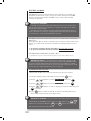
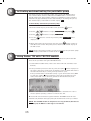
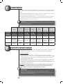
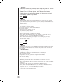
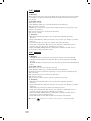
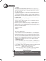
Notice de montage et d’utilisation (à conserver précieusement) Français : page 3 ................................................................................................................................................................................................................................................................................................................ Instructions for installation and use (to be kept in a safe place) English : page 22 ............................................................................................................................................................................................................................................................................................................ Instrucciones de montaje y de uso (a guardar cuidadosamente) Español : página 41 .................................................................................................................................................................................................................................................................................... Montage- und Gebrauchsanleitung (Bitte sicher aufbewahren) Deutsch : seite 60 ................................................................................................................................................................................................................................................................................................ Istruzioni per il montaggio e per l’uso (conservare accuratamente) Italiano : pagina 79 ................................................................................................................................................................................................................................................................................... Montage- und gebruikshandleiding (zorgvuldig bewaren) Nederlands : bladzijde ................................................................................................................................................................................................ 98 Instruções de montagem e de utilização (guarde em lugar seguro) Português : página 117 .......................................................................................................................................................................................................................................... Thank you for choosing the TRi PRO module which integrates both pH regulation and chlorine production control for your swimming pool. From now your pool will become only a source of relaxation and wellbeing, as the TRi PRO module relieves you of tedious manual tasks, whilst providing healthy, clear and more natural water throughout the season. We recommend that you read this user manual carefully before installing and using your TRi PRO unit. Contents 1 Package contents page 23 2 Recommendations page 24 3 Quick install guide page 25 3.1/ Prepare the swimming pool ................................................................................................................................25 3.2/ Installing TRi PRO module .................................................................................................................................25 3.3/ Installing the POD ....................................................................................................................................................... 26 3.4/ Installing pH & ACL sensors ............................................................................................................................. 27 3.5/ Installing the flow switch .....................................................................................................................................28 3.6/ Installing the pH minus injection line .....................................................................................................29 3.7/ Automatic detection (« Plug & Play » TRi PRO module) .....................................................30 3.8/ Testing / Priming the peristaltic pump .................................................................................................30 4 Calibrating pH & ACL sensors page 31 4.1/ pH sensor calibrating procedure .................................................................................................................... 31 4.2/ pH set point ..................................................................................................................................................................... 32 4.3/ Setting the pool size ................................................................................................................................................ 32 4.4/ ACL sensor calibrating procedure ............................................................................................................. 33 4.5/ ACL set point ...................................................................................................................................................................34 5 Activating and deactivating the peristaltic pump page 35 6 Using Zodiac TRI with TRi PRO module page 35 7 Water balance page 36 8 pH & ACL sensors cleaning page 36 9 TRi PRO module maintenance and winterizing page 37 10 Error codes and warnings page 37 10.1/ PH LOW ..................................................................................................................................................................................... 37 10.2/ PH HIGH ................................................................................................................................................................................... 37 10.3/ PH ERROR ..............................................................................................................................................................................38 10.4/ ACL LOW ..................................................................................................................................................................................38 10.5/ ACL HIGH................................................................................................................................................................................. 39 10.6/ ACL ERROR ............................................................................................................................................................................ 39 11 22 Warranty page 40 1 Package contents 1 Zodiac TRi PRO module 2 pH sensor with 5 m armoured cable (blue sensor) 3 ACL sensor with 5 m armoured cable (red sensor) 4 ½’’ threaded cap 5 Hole saw for TRi PRO POD installing 6 Stop washer for intake pipe 7 5 m coil of pipe (pH minus intake & injection) 8 « ORP 700 mV » ACL buffer solution 9 « pH 7,5 » pH buffer solution 10 TRi PRO POD sub-assembly (hose clamp for DN50 & DN63 mm pipes)) 11 Sensor holder (x 2) 12 Teflon tape 13 Ceramic counterweight for intake pipe 3 1 2 11 12 13 8 4 5 6 7 23 9 10 2 Recommendations Important information YOU MUST READ THE FOLLOWING INFORMATION BEFORE PROCEEDING WITH THE INSTALLATION. ALWAYS READ THE USER MANUAL BEFORE USING THE DEVICE. WE RECOMMEND THAT YOU KEEP THE USER MANUAL IN A SAFE PLACE. Zodiac believes in safety first At Zodiac, we take safety seriously. Always exercise caution when using electrical appliances and follow the instructions. Failure to do so could result in permanent injury, electrocution or drowning. Warnings Zodiac water treatment products are designed for domestic swimming pool use only. Inappropriate use could affect performance and void the warranty. Operating a saltwater chlorinator associated with pH regulator without any water flowing through the cell may cause a build-up of flammable gases, which could result in fire or explosion. Keep the equipment out of the reach of children. A damaged supply cord should only be replaced by the manufacturer, authorized service agent or electrician. When installing and using this electrical equipment, always follow basic safety precautions. Before performing installation, disconnect all power. Connect to a circuit that is protected by a ground fault circuit interrupter (GFCI). Service to Zodiac equipment should only be carried out by qualified and authorized pool professionals. Child Safety Children should not be allowed to operate or perform maintenance on this product. No one, particularly children, should sit, step, lean, or climb on any of your pool’s operational system. In the interest of child safety, all components of a pool’s operational system should be located at least 3 meters away from the pool. Electrical Hazard The Zodiac TRi Power pack on which the TRi PRO module is connected must not come into contact with water and should be installed at least 3 meters from the inside wall of your swimming pool. When a lack of water is detected, the unit’s electronic flow switch is designed to turn off the system. Interfering with the electronic flow switch could result in personal injury and/or damage to the cell. 24 3 Quick install guide The following steps will help you set up and operate your new Zodiac TRi PRO module associated with your Zodiac TRi salt water chlorinator. ! IMPORTANT! Your appliance must be installed by a qualified and experienced pool professional. 3.1/ Prepare the swimming pool ! IMPORTANT: the TRi PRO module is designed to automatically ‘MAINTAIN’ the chlorine level (ACL) and pH in your pool. However, it is mandatory to control and adjust water balance parameters before installing this unit. This will help you keeping a correct water balance during the season. Remark: See chapter 7 / ‘Water balance’ to know how to adjust water parameters before installing TRi PRO module. 3.2/ Installing TRi PRO module 1. Switch off the Zodiac TRi salt water chlorinator by pressing the button. (1) 2. Switch off the filtration system by cutting off mains supply into filtration’s electric enclosure. 3. Close the valves cutting off the pipework. 4. Remove the silver cover cap (1). (2) 5. Remove screws holding the original lower module (empty) on the main TRi unit. (2 screws on sides and 2 screws on the bottom) (2). 6. Remove the empty original module and replace it with your new TRi PRO module. Connect the TRi PRO module ribbon cable (flat cable with black male connector) to the corresponding black female connector of the TRi power pack (3). 7. Position the TRi PRO module correctly and tighten the 4 screws. Put the silver cover cap back into place. (3) ! 25 IMPORTANT: Do not connect the unit to mains supply before the TRi PRO module, the POD holding sensors and its pH minus injector pipe are installed (see chapter 3.8 / ‘Testing / Priming the peristaltic pump’). 3.3/ Installing the POD The TRi PRO POD integrates in a single sub-assembly all the necessary elements. That means flow switch (used by your TRi salt water chlorinator), pH sensor, ACL sensor and pH minus one-way valve. Figure illustrating the location of TRi PRO complete system ➤ WARNING : the TRi cell bypass valves must always be fully opened. ! IMPORTANT RECOMMENDATIONS: - TRi PRO POD must always be installed onto a horizontal pipe to be sure that pH & ACL sensor will be positioned vertically. - POD must be the first element installed just after the filter. - If pool is heated (heat pump, heat exchanger, electric heater…), POD will be positioned before heating system (reading made with non heated water). - It is recommended to place the POD at least 20 cm from a bend in the pipe. - pH & ACL sensor cables must not be close to high voltage cables to prevent false readings. NOTE: An incorrectly installed pH and/or ACL sensor may give erroneous measures resulting in inappropriate operation of your TRi equipment. Neither the manufacturer nor the appliance will be held responsible in this case. 1. Choose a straight pipe section with appropriate length after filtration (30 cm minimum, without bend). (1) 2. Disassemble POD sub-assembly (part #10) to keep the bottom part of POD clamp (with 2 holes) (1). 3. Put the bottom part of POD clamp upside down onto dedicated piping place. Use a marker or a centre punch to indicate the location of the 2 holes to be made in the pipe (2). (2) 26 (3) 4. With provided hole saw (part #5), drill the 2 holes for POD supply. Ensure that the holes are perfectly smooth around the edges (3). 5. With provided hole saw (part #5), drill the 2 holes for POD supply. Ensure that the holes are perfectly smooth around the edges. (4) ! WARNING: Water flows through the POD in a certain direction. Please note the direction of the arrows indicating the water flow before installing it! (4). 6. Click the bottom part of the POD clamp onto the upper part already in place on the pipe. Use provided reducer with « EU » mention for DN50 mm pipe. Do not use this reducer for DN63 mm pipe (5). Arrows indicating water flow (5) Reducer (“EU” mark) to be inserted for DN50 mm pipe 7. Position the top part of POD sub-assembly with all its different elements onto the upper part of the POD clamp (beware of the foolproof notch). Firmly tighten the locking ring (hand only tightening !) (6). POD clamp without reducer for DN63 mm pipe (6) 3.4/ Installing pH & ACL sensors For an optimal function, you should follow all the steps below before installing sensors into the POD. Note: (1) - pH sensor (blue, part #2) is designed for reading the pH of pool’s water. - ACL sensor (red, part #3) is made for reading Redox potential (ORP) of pool’s water to automatically adjust chlorine generation (« Active Chlorine Level ») of TRi salt water chlorinator. ➤ Follow instructions hereafter for both pH & ACL sensors. 1. Carefully remove the small protection bottle that contains a preservative liquid by unscrewing its cap. (1). ! (2) 2. Rinse the end of sensor with clear tap water, then shake off any excess of water. WARNING: Never wipe sensors with a cloth or a piece of paper as this could damage it! 3. Set the 2 bottles containing the preservative liquid aside for long term and wintering storage. Empty the preservative liquid solution, filling it with tap water will be sufficient when storing pH & ACL sensors. 4. Introduce pH & ACL sensors (parts #2 & #3) into their respective sensor holders and tighten locking rings by hand. Ensure that sensors are not inserted too far into their housing (see following picture with red dotted line which indicates the driving in limit) (2). 27 5. Now sensors could be connected to TRi control box unit. pH & ACL sensors must then be calibrated before using TRi PRO module (see chapter 4 / ‘Calibrating pH & ACL sensors’). ! (3) WARNING: Follow the colour code of sensor’s cables before plugging it onto TRi control box unit : - BNC socket marked « pH » = pH sensor’s cable (blue plug) - BNC socket marked « ACL » = ACL sensor’s cable (red plug) (3). 3.5/ Installing the flow switch Flow switch is provided with TRi salt water chlorinator. It’s an important safety device made for stopping chlorine generation if a ‘no flow’ situation occurs. ➤ 2 possibilities: a) TRi PRO module installed in the same time as TRi salt water chlorinator b) TRi PRO module installed on a pool already equipped with a TRi unit a) TRi PRO module installed in the same time as TRi unit ! 1. Keep the flow switch from TRi salt water chlorinator. 2. Screw the flow switch in its dedicated threaded adaptor onto the POD (hand tightening only !) WARNING: An arrow on the top of the flow switch indicates water flow. It must be perfectly parallel to the pipe on which the POD is positioned. Arrow indicating water flow b) TRi PRO module installed on a pool already equipped with a TRi unit When swimming pool already has a TRi salt water chlorinator, flow switch is already fitted onto a dedicated hose clamp near the TRi cell. 1. Remove the flow switch from its hose clamp by carefully unscrew its locking ring (filtration off !). 2. Screw the flow switch in its dedicated threaded adaptor onto the POD (hand tightening only !). 3. Fill the empty hole onto original flow switch’s hose clamp by using the provided ½’’ threaded cap and Teflon tape (parts #4 & #12). Remark: It’s also possible to leave the flow switch in its original position on the hose clamp. In this case, the threaded flow switch adaptor on the POD should be removed to seal the hole with the provided threaded cap. This possibility may be useful in order to ensure 100% safety (TRi cell installed on a bypass with valves). 28 3.6/ Installing the pH minus injection line (1) ! IMPORTANT! Always use appropriate safety clothing when handling chemical products (protection glasses, gloves and lab coat) ➤ Installing the injection pipe (peristaltic pump Ð one-way valve): 1. Cut an adequate length of hose from the supplied coil (part #7) to connect the TRi PRO peristaltic pump to the one-way valve located onto the POD. 2. Remove the protective cover of TRi PRO peristaltic pump. 3. Fit the tube onto the threaded output connector on the pump as illustrated in the picture below. The output of peristaltic pump is marked with an arrow pointing downwards on the translucent blue casing (1). 4. Fit the other end of the pipe to the one-way valve located onto the POD (2). (2) pH sensor POD overview with all its equipment (3): pH minus injection Flow switch (3) Installing the intake pipe (container → peristaltic pump): 1. Cut an adequate length of hose from the supplied coil (part #7) to connect the pH minus container to the TRi PRO peristaltic pump. Water flow ACL sensor (4) 2. Fit the tube onto the threaded input connector on the pump as illustrated in the picture below. The suction inlet for the peristaltic pump is marked with an arrow pointing up on the translucent blue casing (4). 3. Drill a hole of appropriate size to accommodate the suction pipe in cap of the pH minus container and also another smaller hole to prevent the container from distorting (“air inlet”). 4. Pull the free extremity of the pipe through the hole drilled in the cap, then place the ceramic weight as well as the nozzle (see picture below, parts #6 & #11) (5). 5. Ensure that ALL connections are safe and watertight before operating the TRi PRO module. (5) 29 6. Put the protection cover of the TRi PRO module peristaltic pump back into place. 3.7/ Automatic detection (« Plug & Play » TRi PRO module) Zodiac TRi power pack will automatically detect the presence of a TRi PRO module. It will display 2 additional lines on the LCD screen, mentioning pH/ ACL CONTROL and pH & ACL set points. 1. After startup, pH/ACL CONTROL will be displayed on the 3rd line on the LCD screen. 2. pH & ACL set points will be displayed on the 4th line of the LCD screen (pH at the left and ACL at the right). In addition, a ^ symbol is displayed at the right of each set point value when measured value by the appliance needs to be automatically corrected. ! REMARKS: 1) pH regulation (peristaltic pump) is not activated as default setting and the LCD screen will display as follows pH ---. Activation will take place automatically approximately 8 hours after it is turned on. To manually activate the pH regulation and display the set point on the LCD screen, refer to the chapter 5 / ‘Activating and deactivating the peristaltic pump’. 2) Default ACL set point is displayed in the bottom right corner of the LCD screen (ACL #1 on the following example). 3.8/ Testing / Priming the peristaltic pump After installation it is recommended to test the peristaltic pump of the TRi PRO module and to prime it (self-priming system). ! WARNING! Before testing the peristaltic pump, check that all the pH minus suction and injection connections are correct. Always use appropriate safety clothes when handling chemical products. To test the peristaltic pump: 1. Turn on the TRi power pack ( 2. Press the 3. Use the 4. Press 5. Use the bouton). button. buttons to display pH\ACL SETUP. to access the pH\ACL SETUP menu. buttons to display TEST ACID. to start the 6. A warning message will be displayed briefly, then press pump test. The peristaltic pump will run for approximately 30 seconds and will stop automatically. If you need to stop the pump immediately, press on the button. 7. Check that the pump has been correctly primed (the pH minus liquid will be visible inside the translucent piping). NOTE: For faster priming of the peristaltic pump, it may be necessary to repeat steps 2 to 7 several times depending on the length of the pH minus injection pipe. 30 4 Calibrating pH & ACL sensors ! IMPORTANT: In order to operate accurately and reliably, it is essential for pH and ACL sensors to be calibrated before operating the TRi salt water chlorinator with the TRi PRO module. To do this, check that the TRi power pack is connected to the mains supply, turn off the pool pump and isolate pH & ACL sensors by closing the valves so as to remove sensors from the POD safely. 4.1/ pH sensor calibrating procedure 1. Remove the pH sensor (blue) from its holder onto the POD (manually unscrew the tightening collar). Rinse the extremity of the pH sensor with clear water and shake it so as to remove any excess water. Do not touch or use a cloth to wipe the glass bulb on the extremity of the pH sensor! (1). (1) 2. Place the pH sensor in a sample of ‘pH 7,5’ blue buffer solution (provided, see picture below). 3. Leave the pH sensor immersed in the buffer solution for approximately 5 minutes in order to ensure a reliable measurement. (2). 4. From the default display on the LCD screen, press the button. 5. Use the buttons to display pH/ACL SETUP, then press 6. Use the buttons to display CALIBRATE pH, then press . . 7. Note the displayed pH value CURRENT pH. If the value is higher than 8,2 or lower than 6,4 there may be a problem with the pH sensor : it is either dirty or may have been damaged during transportation. Clean the pH sensor (see chapter 8 / ‘pH & ACL sensors cleaning’) and repeat steps 1 to 7. If the problem persists, contact your professional retailer for further assistance. (2) 8. If the pH value displayed on the LCD screen CURRENT pH is between 6,4 and 8,2 pH, press to start the calibration process (see pictures hereafter) (3). 9. Once the calibration is completed, note the new pH value displayed CURRENT pH. If the value is different than 7,5 pH, repeat steps 1 to 8 (4). (3) (3) ! (4) 31 10. Press button twice or wait 30 seconds, the TRi power pack will return to the default display on the LCD screen. IMPORTANT NOTES: - In order to ensure that the Zodiac TRi remains fully efficient it is recommended to perform a calibration at least once every two months during the season of pool use. - Ensure that the pH sensor is perfectly clean before starting a calibration operation (Refer to chapter 8 / ‘pH & ACL sensors cleaning’). Then rinse it with clear water, this will ensure that the calibration will be more accurate. 4.2/ pH set point The pH set point is the value to which the Zodiac TRi will adjust the pH in the swimming pool water. This value is always displayed on the LCD screen. The default setting for the TRi PRO module is 7,2 pH. This value corresponds to the ideal compromise so as to achieve optimal efficiency in terms of water disinfection, but it can be changed to adapt to specific pool conditions and requirements. To change the pH set point: 1. Ensure that the pH sensor has been calibrated (see above procedure). 2. From the default display on the LCD screen, press the button. 3. Use the buttons to display pH/ACL SETUP, then press 4. Use the buttons to display pH SETPOINT, then press 5. Use the buttons in order to change the set point value and press . . to validate. button 2 times or wait 30 seconds for the TRi power pack to 6. Press return to the default display on the LCD screen. 4.3/ Setting the pool size To ensure that the pH is regulated under the best conditions for your pool, it is necessary to adapt the settings of the peristaltic pump according to the volume of water in your pool so as to release only the required quantity of pH minus (dosing cycle adjustment). This setting is performed only once when activating the TRi PRO module for the first time, it is not necessary to change it thereafter. It is possible to set 4 different levels corresponding to 4 sizes of swimming pool. List of sizes and corresponding volumes of pool water: - Size #1 : For small pools up to 60 m3 - Size #2 : For mid-size pools between 60 and 90 m3 - Size #3 : For large pools between 90 and 120 m3 - Size #4 : For very large pools more than 120 m3 The above values are only indications, the exact values may vary according to the conditions of use. However, it is recommended not to “over-size” the setting so as to avoid using too much pH minus. NOTE: For safety reasons, default pool size setting is #1 (lowest level). To set the pool size: 1. From the default display on the LCD screen, press the button. 2. Use the buttons to display pH/ACL SETUP, then press 3. Use the buttons to display SET POOL SIZE, then press . . buttons to select the pool size corresponding to your 4. Use the pool volume (default setting is #1). to confirm your choice then press button 2 times or wait 5. Press 30 seconds for the TRi power pack to return to the default display on the LCD screen. 32 ! NOTE: One dose of pH minus is released in the pool every 2 hours (when filtration system and TRi unit are both operating). WARNING! It is not recommended to oversize the pool size setting in order to avoid pH minus overdosing. 4.4/ ACL sensor calibrating procedure 1. Remove the ACL sensor (red) from its holder onto the POD (manually unscrew the tightening collar). Rinse the extremity of the pH sensor with clear water and shake it so as to remove any excess water. Do not touch or use a cloth to wipe the glass bulb on the extremity of the pH sensor! (1). (1) 2. Place ACL sensor in a sample of ‘ORP 700 mV’ orange buffer solution (provided, see picture below). 3. Leave the ACL sensor immersed in the buffer solution for approximately 5 minutes in order to ensure a reliable measurement (2). 4. From the default display on the LCD screen, press the button. 5. Use the buttons to display pH/ACL SETUP, then press . 6. Use the buttons to display CALIBRATE ACL, then press . 7. Displayed ACL value on the LCD screen CURRENT ACL could have 3 different (2) to start the values : HIGH, LOW or OK. Press calibration process (see pictures below) (3). 8. Once the calibration is completed, ACL value should be OK (CURRENT ACL). If the displayed value is not OK, repeat steps 1 to 7 (4). 9. Press button twice or wait 30 seconds, the TRi power pack will return to the default display on the LCD screen. (3) (3) ! (4) 33 IMPORTANT NOTES: - In order to ensure that the Zodiac TRi remains fully efficient, it is recommended to perform a calibration at least once every two months during the season of pool use. - Ensure that the ACL sensor is perfectly clean before starting a calibration operation (Refer to chapter 8 / ‘pH & ACL sensors cleaning’). Then rinse it with clear water, this will ensure that the calibration will be more accurate. 4.5/ ACL set point TRi PRO ACL function (« Active Chlorine Level ») made for automatically ‘maintain’ chlorine level to get a good pool’s water disinfection. TRi PRO module continuously measures the ORP level to control TRi salt water chlorinator operation. ! IMPORTANT REMARKS: > the ACL set point displayed on the LCD screen does not correspond to free chlorine level into pool’s water ! It is only the selected level of ‘water’s disinfection potential’ (ACL). > The ACL set point required in order to obtain the optimal free chlorine level is different for each pool. A regular manual chlorine level analysis will be necessary to correctly adjust the ACL set point. TRi PRO module has 6 different ACL set points (corresponding to 6 different ORP levels). The higher the ACL set point is, the higher the requested “disinfectant action” will be, as a result the free chlorine level will be potentially higher, and vice versa. To increase potential chlorine generation: increase ACL set point To decrease potential chlorine generation: decrease ACL set point TRi PRO module default ACL set point is #1. (*) (*) : Default ACL set point could be different depending on your unit software version. ! IMPORTANT NOTE: It is recommended to set the ACL set point to #3 or #4 during the first few days after having installed the TRi PRO module in order to quickly stabilise the free chlorine level (see chapter 7 / ‘Water balance’). If the free chlorine level is correct after this start-up period, it will be necessary to adjust the ACL set point accordingly. To change the ACL set point: 1. Ensure that the ACL sensor has been calibrated (see above procedure). 2. From the default display on the LCD screen, press the button. 3. Use the buttons to display pH/ACL SETUP, then press 4. Use the buttons to display ACL SETPOINT, then press 5. Use the to validate. buttons in order to change the set point value and press . . button 2 times or wait 30 seconds for the TRi power pack to 6. Press return to the default display on the LCD screen. ! IMPORTANT REMARK: It is not possible to manually adjust the chlorine output when the TRi PRO module is fitted on a TRi power pack ( buttons are inoperative). Only the TRi salt water chlorinator user manual). 34 and modes are active (see 5 Activating and deactivating the peristaltic pump For safety reasons, the peristaltic pump of the Zodiac TRi PRO module is not activated when delivered. When the TRi PRO module is connected to the TRi power pack, the peristaltic pump is programmed to start operating automatically approximately 8 hours after turning it on. During this period, the default display on the LCD screen will display pH ---. To immediately activate the peristaltic pump: 1. From the default display on the LCD screen, press the button. 2. Use the buttons to display pH/ACL SETUP, then press 3. Use the buttons to display ACID PAUSED. 4. Press the displayed). . button to activate the peristaltic pump (ACID ENABLED will be 5. When appropriate option has been selected, press button 2 times or wait 30 seconds for the TRi power pack to return to the default display on the LCD screen. NOTE: Use the opposite procedure in order to deactivate the peristaltic pump (default display on the LCD screen will return to pH ---). 6 Using Zodiac TRI with TRi PRO module The Zodiac TRi is now ready to automatically regulate the pH and the ACL levels in the pool water using the TRi PRO module. 1. Set the ‘ON’ and ‘OFF’ times (refer to the Zodiac TRi Salt chlorinator user manual). 2. If the pool water pH exceeds the set point, the symbol ^ will be displayed to the right of the pH set point value on the LCD screen. pH minus will then be released automatically according to the predefined cycles. If the pool water ACL is unsuitable to keep a good disinfectant effect (ORP too low), the symbol ^ will be displayed to the right of the ACL set point value on the LCD screen. Chlorine generation will automatically start according to the predefined cycles. 3. Refer to the instructions concerning water balance hereunder in order to ensure optimal operating conditions for the Zodiac TRi. Zodiac TRi Salt chlorinator together with the TRi PRO module will now automatically maintain the appropriate pH and ACL levels for the pool water. NOTE: The TRi PRO module is designed to use only pH minus (therefore to lower the pH). Do NOT use other types of chemicals. 35 7 Water balance The Zodiac TRI with the TRi PRO module is designed to disinfect the swimming pool water via its controlled salt electrolysis function and to maintain the pH level. The following information concerning the values to be respected for a correct water balance is essential in order to fully enjoy your pool. Ensuring that the pool water balance is correct from the start will reduce the probability of encountering problems during the first days of operation or during the season of use of your pool. ! pH Recommended values with TRi PRO 7,2 – 7,4 To increase Deactivate the peristaltic pump or add pH plus To reduce Tests frequency (bathing season) 8 REMARK: Even if TRi PRO module is an automatic regulation for ACL and pH, it is mandatory to make some manual water analysis regularly to check water balance parameters. Free chlorine TAC TH (total alcalinity or buffer effect) (calcium hardness) mg/L or ppm °f (ppm) °f (ppm) 0,5 – 2,0 8 – 15 (80 – 150) 10 – 30 (100 – 300) Increase ACL Add alkalinity cor- Add calcium chloset point or use rector (« TAC+ ») ride ‘Boost’ mode Decrease ACL set Add calcium catAdd pH minus point or Add hydrochloric cher or make a (automatic with acid switch off the TRi decarbonation TRi PRO module) unit Weekly Weekly Monthly Monthly Cyanuric acid Salt level Metals (Cu, Fe, Mn…) (stabilizer) mg/L or ppm g/L or kg/m3 mg/L or ppm < 30 4 ≈0 Add cyanuric acid (only if necessary) Add salt / Partially drain the pool and refill with clear water Leave it or partially drain the pool and refill with fresh water Add metals catcher Quarterly Quarterly Quarterly pH & ACL sensors cleaning To ensure that the TRi PRO module will operate under optimal conditions, it is recommended to clean sensors (ph and/or ACL) before each calibration. To clean a sensor: - If the extremity of the sensor is covered with a greasy film (cosmetics deposit, sun lotion….), place it for a few minutes in tepid soapy water. Do NOT use detergent products but rather a liquid dishwashing product. Then rinse profusely using clear water. - If the extremity of the sensor is covered with calcium buildup or if the above procedure was not sufficient, place the sensor in a 10% hydrochloric acid solution for a few minutes (wear all necessary protective clothing).Then rinse profusely using clear water. Remark: It is possible to buy this acid cleaning solution from your local swimming pool retailer. Then rinse profusely the pH tester with clear water and proceed with the calibration before using it. ! IMPORTANT: - Always clean pH & ACL sensors before performing a calibration. - NEVER WIPE THE SENSORS WITH A CLOTH but shake it gently in order to remove any excess rinse water. 36 9 TRi PRO module maintenance and winterizing Using the TRi PRO module allows for more freedom when monitoring the pool parameters. However, it is necessary to check a number of settings on a regular basis so as to ensure a correct and safe operation of the system. NOTE: Your TRi PRO module uses a peristaltic pump that is designed to release only pH minus. Do NOT use hydrochloric acid, pH plus or any other chemicals. TRi PRO module winterizing: - When you want to winterize your TRi PRO module at the end of the season, it is recommended to let it pump clear water instead of the pH minus so as to rinse out the peristaltic pipe. This pipe can be simply cleaned by using the peristaltic pump Testing and Priming function (see chapter 3.8 / ‘Testing / Priming the peristaltic pump’). - Remove the pH & ACL sensors from their respective holders. Store sensors in their original bottle or in a bottle of water filled with tap water. Seal sensor holders if necessary. ! VERY IMPORTANT: NEVER let a sensor dry out, this would damage it permanently. 10 Error codes and warnings 10.1/ PH LOW Meaning: Pool water pH is 0,4 pH lower than the set point displayed on the LCD screen. pH value should be manually checked before proceeding. Possible causes: pH sensor needs to be cleaned and calibrated. pH sensor is worn out and/or faulty. This could also mean that the selected set point is too high or that the selected pool size is too high. Solutions: - Clean then calibrate the pH sensor (see chapter 8 / ‘pH & ACL sensors cleaning’ and 4.1 / ‘pH sensor calibrating procedure’). - Replace the pH 7,5 buffer solution, then calibrate the pH sensor. - Check the selected value for pH set point. - Check the pool size setting (see chapter 4.3 / ‘Setting the pool size’). - If necessary, replace the pH sensor. 10.2/ PH HIGH Meaning: Pool water pH is 0,4 pH higher than the set point displayed on the LCD screen. pH value should be manually checked before proceeding. Possible causes: pH sensor needs to be cleaned and calibrated. pH sensor is worn out and/or faulty. This could also mean that the selected set point is too low or that the selected pool size is too low. 37 Solutions: - Clean then calibrate the pH sensor (see chapter 8 / ‘pH & ACL sensors cleaning’ and 4.1 / ‘pH sensor calibrating procedure’). - Replace the pH 7,5 buffer solution, then calibrate the pH sensor. - Check the selected value for pH set point. - Check the pool size setting (see chapter 4.3 / ‘Setting the pool size’). - If necessary, replace the pH sensor. 10.3/ PH ERROR Meaning: - The peristaltic pump of the TRi PRO module has operated for full dosage cycles without achieving the defined set point (displayed on the LCD screen). - The peristaltic pump of the TRi PRO module has not operated since more than 72 hours. Possible causes: The pH minus container is empty. pH sensor needs to be cleaned and calibrated. pH sensor is faulty. Selected pool size setting is too low The peristaltic pump is defused. Solutions: - Replace the pH minus container if it is empty. - Clean, then calibrate the pH sensor (see chapter 8 / ‘pH & ACL sensors cleaning’ and 4.1 / ‘pH sensor calibrating procedure’). - Check the pool size setting (see chapter 4.3 / ‘Setting the pool size’). - Check the peristaltic pump operation (see chapter 3.8 / ‘Testing / Priming the peristaltic pump’). Hold the button for 3 seconds to erase an error code (when it blinks). 10.4/ ACL LOW Meaning: Water disinfectant poser is too low (ACL). Free chlorine level into pool’s water is probably too low. A manual free chlorine analysis should be done before proceeding. Possible causes: Water pH is too high. Total alkalinity (TAC) is too low, which means an unstable pH. ACL set point is too low. A high bather load has generated a high chlorine demand. ACL sensor needs to be cleaned and calibrated. ACL sensor is faulty. Solutions: - Manually check the pH value to be sure that pH regulation operates correctly. - Check total alkalinity (TAC) and adjust it if necessary (see chapter 7 / ‘Water balance’). - Increase the ACL set point (see chapter 4.5 / ‘ACL set point ‘). - Clean, then calibrate the ACL sensor (see chapter 8 / ‘pH & ACL sensors cleaning’ and 4.1 / ‘pH sensor calibrating procedure’). - Replace the ORP 700 mV buffer solution, then calibrate the ACL sensor. - If necessary, replace the ACL sensor. 38 10.5/ ACL HIGH Meaning: Water disinfectant poser is too high (ACL). Free chlorine level into pool’s water is probably too high. A manual free chlorine analysis should be done before proceeding. Possible causes: Water pH is too low. Total alkalinity (TAC) is too low, which means an unstable pH. ACL set point is too high. Swimming pool has been covered and/or unused during a long period (cover, shelter, cold climate…). ACL sensor needs to be cleaned and calibrated. ACL sensor is faulty. Solutions: - Manually check the pH value to be sure that pH regulation operates correctly. - Check total alkalinity (TAC) and adjust it if necessary (see chapter 7 / ‘Water balance’). - Decrease the ACL set point (see chapter 4.5 / ‘ACL set point ‘). - Clean, then calibrate the ACL sensor (see chapter 8 / ‘pH & ACL sensors cleaning’ and 4.1 / ‘pH sensor calibrating procedure’). - Replace the ORP 700 mV buffer solution, then calibrate the ACL sensor. - If necessary, replace the ACL sensor. 10.6/ ACL ERROR Meaning: - TRi PRO salt water chlorinator has produced chlorine for more than 30 cumulative hours without reaching the ACL set point (displayed onto LCD screen). - TRi PRO salt water chlorinator has not operated for more than 30 cumulative hours. Possible causes: Water pH is not correct (too high or too low). Total alkalinity (TAC) is too low, which means an unstable pH. Unsuitable chlorine generation regarding to pool’s chlorine demand (wrong ACL set point). ACL sensor needs to be cleaned and calibrated. ACL sensor is faulty. TRi electrode is scaled or worn (chlorine generation too low). Solutions: - Manually check the pH value to be sure that pH regulation operates correctly. - Check total alkalinity (TAC) and adjust it if necessary (see chapter 7 / ‘Water balance’). - Adjust ACL set point (see chapter 4.5 / ‘ACL set point ‘). - Clean, then calibrate the ACL sensor (see chapter 8 / ‘pH & ACL sensors cleaning’ and 4.1 / ‘pH sensor calibrating procedure’). - Replace the ORP 700 mV buffer solution, then calibrate the ACL sensor. - If necessary, replace the ACL sensor. - Check TRi electrode (see TRi salt water chlorinator user manual) Hold the 39 button for 3 seconds to erase an error code (when it blinks). 11 Warranty a > Conditions We have taken utmost care in manufacturing this product which has benefited from our extensive technical experience and also from continuous quality controls. We regularly introduce improvements or modifications to our models in order to integrate technological progress. For obvious reasons it is impossible for us to add such improvements to our previous models as part of our warranty. If, despite the care and know-how we put into manufacturing our products, you have to call upon our warranty, this latter will only apply to the free replacement of the faulty parts. Shipping and labor costs will remain at your charge. This device has been specially designed for the European, North African and Near and Middle Eastern markets and cannot be sold outside these zones. Moreover, this appliance is not guaranteed outside of Europe, North Africa and countries of the Near and Middle East. b > Warranty period The Zodiac TRi PRO module is covered by a warranty of 2 years (24 months) following its initial purchase (date on the invoice as proof), except for wearing parts. c > Object of the warranty Only the “power pack” of the Zodiac TRi PRO module is covered by this warranty (main control unit, electronic board and peristaltic pump motor). During the period covered by the warranty as defined here-above, any part which Zodiac has recognized as being faulty will be repaired or replaced with a new part or a fully functional part. In any case, transportation and labor costs will remain at the user’s cost. If the product needs to be returned to us, shipping expenses to and from our workshop will be at the user’s expense, labor costs however will be supported by the manufacturer. Immobilization and deprivation of use of a device in the case of repair will not entitle the users to any compensation. Concerning the following parts : - one-way valve - peristaltic tube - pH sensor - ACL sensor - pH 7,5 and ORP 700 mV buffer solutions These are considered to be subject to normal wear and are therefore not covered by the warranty as defined above. Only the legal warranty covering against hidden manufacturing flaws will apply to these parts. Zodiac will not be held responsible in the case of incorrect installation and/or in the case of failure to comply with the safety regulations and recommendations mentioned in this manual. Using water from a well is forbidden and will void the warranty if this proves to be the cause of any potential defect or damage. In any case, the seller’s legal warranty remains in force with reference to article 4 of decree n°78-464 dated 24 March 1978. The legal warranty stipulated under article 1641 of the civil code will apply. d > Damage during transport The devices are shipped at the user’s risk. It is the user’s responsibility to check that the product is in perfect condition before accepting delivery, and if necessary to write down any reservations and comments on the transportation/delivery slip. Our responsibility will not be engaged in this respect. e > Jurisdiction, litigation and dispute The present warranty is governed by French law and by any European Directives and international treaties in force at the time of the claim, as enforceable in France. Jurisdiction will be attributed exclusively to French courts in the case of dispute concerning its interpretation or its execution. Register your product on our website: - You will be the first to be informed of new Zodiac products and special offers. - You can help us to constantly improve our product quality. www.zodiac-poolcare.com ! For any warranty issue, please contact your local dealer. We recommend that you keep your purchase invoice carefully if you require assistance for your product. 40