1
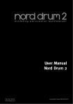
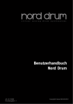
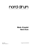
User Manual Nord Drum 2 OS version 3.0x Part No. 50416 Print Edition: F Copyright Clavia DMI AB The lightning flash with the arrowhead symbol within an equilateral triangle is intended to alert the user to the presence of uninsulated voltage within the products enclosure that may be of sufficient magnitude to constitute a risk of electric shock to persons. CAUTION - ATTENTION RISK OF ELECTRIC SHOCK DO NOT OPEN RISQUE DE SHOCK ELECTRIQUE NE PAS OUVRIR Le symbole éclair avec le point de flèche à l´intérieur d´un triangle équilatéral est utilisé pour alerter l´utilisateur de la presence à l´intérieur du coffret de ”voltage dangereux” non isolé d´ampleur suffisante pour constituer un risque d`éléctrocution. CAUTION: TO REDUCE THE RISK OF ELECTRIC SHOCK DO NOT REMOVE COVER (OR BACK). NO USER SERVICEABLE PARTS INSIDE. REFER SERVICING TO QUALIFIED PERSONNEL. The exclamation mark within an equilateral triangle is intended to alert the user to the presence of important operating and maintenance (servicing) instructions in the literature accompanying the product. ATTENTION:POUR EVITER LES RISQUES DE CHOC ELECTRIQUE, NE PAS ENLEVER LE COUVERCLE. AUCUN ENTRETIEN DE PIECES INTERIEURES PAR L´USAGER. CONFIER L´ENTRETIEN AU PERSONNEL QUALIFE. AVIS: POUR EVITER LES RISQUES D´INCIDENTE OU D´ELECTROCUTION, N´EXPOSEZ PAS CET ARTICLE A LA PLUIE OU L´HUMIDITET. Le point d´exclamation à l´intérieur d´un triangle équilatéral est employé pour alerter l´utilisateur de la présence d´instructions importantes pour le fonctionnement et l´entretien (service) dans le livret d´instructions accompagnant l´appareil. Instructions pertaining to a risk of fire, electric shock or injury to persons. IMPORTANT SAFETY INSTRUCTIONS SAVE THESE INSTRUCTIONS Warning - When using electric products, basic precautions should always be followed, including the following: 1) Read these instructions. 10) Protect the power cord from being walked on or pinched particularly at plugs, convenience receptacles, and the point 2) Keep these instructions. where they exit from the apparatus. 3) Heed all warnings. 11) Only use attachments/accessories specified by the manufacturer. 4) Follow all instructions. 5) Do not use this apparatus near water. 6) Clean only with dry cloth. 7) Do not block any ventilation openings. Install in accordance with the manufacturer’s instructions. 8) Do not install near any heat sources such as radiators, heat registers, stoves, or other apparatus (including amplifiers) that produce heat. 12) Use only with the cart, stand, tripod, bracket, or table specified by the manufacturer, or sold with the apparatus. When a cart is used, use caution when moving the cart/apparatus combination to avoid injury from tip-over. 13) Unplug this apparatus during lightning storms or when unused for long periods of time. 9) Do not defeat the safety purpose of the polarized or grounding-type plug. A polarized plug has two blades with one wider than the other. A grounding type plug has two blades and a third grounding prong. The wide blade or the third prong are provided for your safety. If the provided plug does not fit into your outlet, consult an electrician for replacement of the obsolete outlet. 14) Refer all servicing to qualified service personnel. Servicing is required when the apparatus has been damaged in any way, such as power-supply cord or plug is damaged, liquid has been spilled or objects have fallen into the apparatus, the apparatus has been exposed to rain or moisture, does not operate normally, or has been dropped. No naked flame sources, such as lighted candles, should be placed on the apparatus; Il convient de ne pas placer sur l´appareil de sources de flammes nues, telles que des bougies allumées; Do not use the apparatus in tropical climates. L´appareil n’est pas destiné á étre utilisé sous un climat tropical. Additional Safety Information WARNING: To reduce the risk of fire or electric shock, do not expose this apparatus to rain or moisture. The apparatus shall not be exposed to dripping or splashing and that no objects filled with liquids, such as vases, shall be placed on the apparatus. L´appareil ne doit pas étre exposé á des égouttements d´eau ou des éclaboussures et de plus qu´aucun objet rempli de liquide tel que des vases ne doit étre placé sur l´appareil. The maims plug is used as the disconnect device and shall remain readily operable. Lorsque la prise du résau d’alimentation est utilisée comme dispositif de déconnexion, ce dispositif doit demeuré aisément accessible. Trademarks: The Nord logo is trademark of Clavia DMI AB. All other trademarks mentioned in this publication are the properties of their respective holders. Specifications and appearances are subject to change without notice. Copyright © Clavia DMI AB Nord Drum 2 - Table of Contents 1 Overview Thank you! . . . . . . . . . . . . . . . . . . . . . Attaching the stand holder . . . . Connections . . . . . . . . . . . . . . . . . . . Phones . . . . . . . . . . . . . . . . . . . . . . . . . . Left, Right Out . . . . . . . . . . . . . . . . . . . . MIDI In . . . . . . . . . . . . . . . . . . . . . . . . . . MIDI Out . . . . . . . . . . . . . . . . . . . . . . . . . Trig Inputs CH 1 – CH 6 . . . . . . . . . . . . . Power . . . . . . . . . . . . . . . . . . . . . . . . . . . Parameter names . . . . . . . . . . . . . . The Panel . . . . . . . . . . . . . . . . . . . . . Channel Select . . . . . . . . . . . . . . . . . . . Input Trig Level LEDs . . . . . . . . . . . . . . Peak/Focus LEDs . . . . . . . . . . . . . . . . . Trig/Mute Group LEDs . . . . . . . . . . . . . . Lower Param . . . . . . . . . . . . . . . . . . . . . Dial . . . . . . . . . . . . . . . . . . . . . . . . . . . . Shift/Exit . . . . . . . . . . . . . . . . . . . . . . . . Solo Edit . . . . . . . . . . . . . . . . . . . . . . . . . Trig/Tap (Trig) . . . . . . . . . . . . . . . . . . . . Trig Level . . . . . . . . . . . . . . . . . . . . . . . . Program . . . . . . . . . . . . . . . . . . . . . . . . . 4 4 4 4 4 4 4 5 5 6 6 6 7 7 7 7 7 7 8 8 8 8 2 Getting Started Connect a Nord Pad . . . . . . . . . . . . 9 Connecting pads . . . . . . . . . . . . . . . 9 Adjust Input sensitivity . . . . . . . . 9 Threshold . . . . . . . . . . . . . . . . . . . . . 10 Nord Pad - Inp Sens & Thres . 10 MIDI Channel . . . . . . . . . . . . . . . . . 10 MIDI Note assignment . . . . . . . . 10 MIDI Note Learn . . . . . . . . . . . . . . 11 Changing programs . . . . . . . . . . . 11 Play the Demo . . . . . . . . . . . . . . . . 12 Memory Protect . . . . . . . . . . . . . . . 12 Storing . . . . . . . . . . . . . . . . . . . . . . . . 12 3 Reference Channels & signal flow . . . . . . . The Parameters . . . . . . . . . . . . . . . Master Level . . . . . . . . . . . . . . . . . . . . Store . . . . . . . . . . . . . . . . . . . . . . . . . . Program/Value LED display . . . . . . . . Mute Group . . . . . . . . . . . . . . . . . . . . . Edit Group . . . . . . . . . . . . . . . . . . . . . . Edit Group Paste . . . . . . . . . . . . . . . . . Noise Parameters . . . . . . . . . . . . Filter Freq . . . . . . . . . . . . . . . . . . . . . . Filt Type . . . . . . . . . . . . . . . . . . . . . . . . Filter Env (Dyn Filter) . . . . . . . . . . . . . . Filt Res . . . . . . . . . . . . . . . . . . . . . . . . . Attack/Rate . . . . . . . . . . . . . . . . . . . . . Atk Mode (Env Mode) . . . . . . . . . . . . . . Decay . . . . . . . . . . . . . . . . . . . . . . . . . Dec Lo (Type/Dyn) . . . . . . . . . . . . . . . . Tone Parameters . . . . . . . . . . . . . Spectra . . . . . . . . . . . . . . . . . . . . . . . . Wave . . . . . . . . . . . . . . . . . . . . . . . . . . Timb Env (Dyn Timb) . . . . . . . . . . . . . . 13 13 13 13 13 14 14 14 14 14 14 15 16 16 16 17 17 18 18 18 18 Timbre . . . . . . . . . . . . . . . . . . . . . . . . . Timb Dec (Hi Decay) . . . . . . . . . . . . . . Punch . . . . . . . . . . . . . . . . . . . . . . . . . . Decay . . . . . . . . . . . . . . . . . . . . . . . . . Dec Lo (Type Dyn) . . . . . . . . . . . . . . . . Pitch . . . . . . . . . . . . . . . . . . . . . . . . . . Scl Pre . . . . . . . . . . . . . . . . . . . . . . . . . Bend . . . . . . . . . . . . . . . . . . . . . . . . . . Bend Time . . . . . . . . . . . . . . . . . . . . . . 19 19 19 19 20 20 20 20 21 Click Parameters . . . . . . . . . . . . . 21 Level . . . . . . . . . . . . . . . . . . . . . . . . . . . 21 Type . . . . . . . . . . . . . . . . . . . . . . . . . . . 21 Mix Parameter . . . . . . . . . . . . . . . 21 Channel Parameters . . . . . . . . . .21 Distort . . . . . . . . . . . . . . . . . . . . . . . . . Distortion Type . . . . . . . . . . . . . . . . . . . Eq Freq . . . . . . . . . . . . . . . . . . . . . . . . Gain . . . . . . . . . . . . . . . . . . . . . . . . . . . Echo (Repeat) . . . . . . . . . . . . . . . . . . . Echo Amount . . . . . . . . . . . . . . . . . . . . Echo BPM (Repeat Tempo) . . . . . . . . . Level . . . . . . . . . . . . . . . . . . . . . . . . . . Pan . . . . . . . . . . . . . . . . . . . . . . . . . . . . Global Settings . . . . . . . . . . . . . . Copy . . . . . . . . . . . . . . . . . . . . . . . . . . Paste . . . . . . . . . . . . . . . . . . . . . . . . . . Init Sound . . . . . . . . . . . . . . . . . . . . . . Clean Sound . . . . . . . . . . . . . . . . . . . . Panic . . . . . . . . . . . . . . . . . . . . . . . . . . System . . . . . . . . . . . . . . . . . . . . . . . . MIDI . . . . . . . . . . . . . . . . . . . . . . . . . . . Trig Type . . . . . . . . . . . . . . . . . . . . . . . Inp Thres . . . . . . . . . . . . . . . . . . . . . . . Inp Sens, Dynamics . . . . . . . . . . . . . . 21 21 22 22 22 22 22 22 22 22 23 23 23 23 23 23 24 24 25 25 Updating the OS . . . . . . . . . . . . . . 27 Website . . . . . . . . . . . . . . . . . . . . . . . . 27 4 Nord Drum 2 Manager MIDI Interface . . . . . . . . . . . . . . . . . . . . 28 Get Banks . . . . . . . . . . . . . . . . . . . . . . 28 Send Banks . . . . . . . . . . . . . . . . . . . . . 28 5 MIDI MIDI Operation . . . . . . . . . . . . . . . 29 Global & Individual MIDI . . . . . . . . . . . . 29 Global MIDI Channel . . . . . . . . . . . . . . 29 Individual MIDI Channels . . . . . . . . . . . 29 Recording: Global MIDI Ch . . . . 29 Recording parameter changes . . . . . . 29 Recording: Indiv. MIDI Ch . . . . 30 Pitch control on Indivi. MIDI Channels . 30 MIDI Controller . . . . . . . . . . . . . . . . Nord Beat . . . . . . . . . . . . . . . . . . . . . Storing the memory content . . Receive Sys Ex Data . . . . . . . . . . MIDI CC Numbers . . . . . . . . . . . . . 30 31 31 31 32 6 Appendix Stand setup . . . . . . . . . . . . . . . . . . . 33 7 Index Index . . . . . . . . . . . . . . . . . . . . . . . . . . 34 4 | Nord Drum 2 User Manual OS v3.0x 1 Overview Thank you! Connections Thank you for purchasing the Nord Drum 2. We have designed this musical instrument to be a one of a kind drum synthesizer for drummers, percussionists and producers, seeking unique and playable percussive sounds. Phones You are probably eager to start using the Nord Drum 2 right away, but please spend a few minutes with the first pages of this manual. This will give you a good start on how to hook it up, and to access the amazing features. Left, Right Out Connect a low impedance stereo headphone to the Phones output. This is a 1/8" (mini) jack. The L and R outputs are unbalanced ¼" jacks with line level signals. EE The Nord Drum 2 is capable of producing sounds with a very wide dynamic and frequency range. Be careful when you use the unit and when you edit the sounds. Attaching the stand holder MIDI In Connect the MIDI Input to a drum pad or a sequencer if you want to control the Nord Drum 2 with incoming MIDI messages. The MIDI Input is also used when you update the unit with new operating systems. The stand holder is used to mount the Nord Drum 2 on a stand that is equipped with a clamp. The diameter is 23 millimeter (0.9 inches) which will fit most general purpose clamps. MIDI Out Connect the MIDI Output to a computer or sequencer to record what’s played on the Nord Pad or other pads connected to the Trig Inputs. The performance will be transmitted as MIDI notes, which also can be used to trigger other MIDI units. MIDI Output is used with the Program Dump feature to transfer the settings of the programs in the Nord Drum 2 via MIDI. NORD PAD INPUT POWER CH CH46 CH 5 CH 4 CH 3 CH2 CH 1 RIGHT OUT LEFT OUT PHONES Chapter 1 Overview Trig Inputs CH 1 – CH 6 Power Connect drum pads or other signal sources to the Trig Input ¼" jacks. These inputs can be used with a variety of different signals. The sensitivity and the threshold of the inputs can be adjusted with the Inp Sens and Inp Thres parameters, read more about this in the following chapter. Connect the Nord Drum 2 power supply to the Power input. If the original supply is not available, use only a 12 volt DC, 250 mA adapter, with a barrel type plug that has the positive current on the tip. The outer diameter of the plug is 5.5 millimeter and the inner diameter is 2.1 millimeter. EE Do not connect pads while the Nord Drum 2 is turned on, this will trigger the sounds. EE Always turn on the Nord Drum 2 first and the sound system last, and reverse this order when you want to turn it off again. The Nord Drum 2 has been developed and tested with different pad and trigger types. The Trig Inputs are designed to be very versatile and is compatible with many different types of signals. MM If you experience double triggered sounds, flams or a slow response from the Nord Drum 2, make sure that you adjust the Trig Type, Inp Thres and Inp Sens parameters. Read more on how to adjust these settings on page 9 Nord Pad Input Connect a Nord Pad to the RJ45 connector, using the CAT6 cable that is supplied with the Nord Pad. EE This connection can not be used with any other equipment. Do not try and connect a computer network or any other RJ45 equipped unit to the Nord Drum 2. If you want to add a kick drum pad to the Nord Drum 2 while using the Nord Pad, connect the kick pad to the CH 1 input. The other inputs are disabled when the Nord Pad is connected. | 5 6 | Nord Drum 2 User Manual OS v3.0x Parameter names The Panel Please note: Some parameters on the Nord Drum 2 panel have had their names changed since the release of version 2.1. This manual will use the new names in the text and illustrations but the old names will be included in (round brackets). The buttons, the LED display and the Dial are used when you select a program and when you edit the sounds in the Nord Drum 2. Old name New name Dyn Filter Filt Env Atk/Rate Attack/Rate Env Mode Atk Mode Type/Dyn (Noise) Dec Lo Repeat Echo Dyn Timb Timb Env Hi Decay Timb Dec Type/Dyn (Tone) Dec Lo Trig (Button) Trig/Tap Repeat Tempo Echo BPM Channel Select There are six channels, each channel represents one sound. Press the Channel Select buttons repeatedly to change and select the channel to be triggered with the Trig/Tap button on the panel and/or to be edited. The red Focus LEDs will indicate which channel is selected and will stay lit when you are editing a sound. You can use pads to quickly select the channel to edit, if no channel has been previously selected with a Channel Select button. If a Channel Select button has been used to manually select a channel, press the Program button once, strike a pad to select the channel and then a parameter button to return to editing that channel. Chapter 1 Overview Input Trig Level LEDs button or by pressing the Row Select button will move the edit focus to the second row parameter. Lower Param The Input LEDs are used to indicate channel activity, if a channel is triggered, being edited or part of a Mute or Edit Group. Read more about Groups on page 14. Peak/Focus LEDs The upper red LEDs will flash when a trigger input receives a signal from the pad or trigger device. This indication can be used to make sure that you utilize the full dynamic range of the Nord Drum 2. The red Peak LED should be lit with a longer duration when you play with your maximum force. If it blinks (which it does 3 dB below the maximum), you can increase the Input Sensitivity, see page 9. EE The red LEDs do not indicate overload or distortion in the audio signal path of the Nord Drum 2. Trig/Mute Group LEDs The lower green LEDs will blink on channel activity. Solid green LEDs indicates which channels are in the Mute Group. Parameters are accessed with the row of eight buttons. Press one of the buttons to begin to edit a sound. Settings are changed when the Dial is turned. If a button activates a parameter in the upper row, a quick double-tap on the same When you want to see the setting of, or edit one of the parameters with the red labels, hold down the “Lower Param” button. Another method is to hold down that particular parameter button. Dial Turn the Dial to select programs and to change the setting of a selected parameter when you are editing a sound. The Dial is sensitive to the speed of the turning action. A quick twist to the left or the right can set a parameter to its lowest or highest value. Certain parameters have a basic setting in the middle between the highest and lowest settings, Bend is one of these with 0 Bend in the middle of the range. Twist the Dial quickly and the setting will make a stop in this center setting. Shift/Exit The Shift button is used together with the buttons to access additional parameters. These additional parameters are labeled with the text below the buttons. The System, MIDI and Inp Sens parameters have more than one setting. These are accessed by pressing repeatedly on the buttons. | 7 8 | Nord Drum 2 User Manual OS v3.0x Press the Shift button to exit a store operation, or to exit editing the additional parameters. Solo Edit Solo Edit allows you to hear only the section (Noise, Tone or Click) that is currently being edited. In addition, the channel in focus will be soloed in regard to incoming MIDI notes. Trig/Tap (Trig) Trig: Use the Trig/Tap (Trig) button to trigger a selected channel. Tap: You can set the Echo tempo by tapping. Hold the Shift and Echo BPM button, and tap repeatedly on the Trig/Tap (Trig) button. Four taps are needed to set a tempo. Dots in the lower part of the LED display will show the progress of the beats as you tap. Trig Level Adjust the Trig/Tap button’s output velocity. Range: 1 - 20 Program Press the Program button to the left of the display to return to selecting programs with the Dial. Chapter 2 Getting Started 2 Getting Started 3 The red Peak/Focus LEDs will indicate the trigger strength with a quick flash when the trigger signal strength is “almost there” and with a longer flash when you have correctly matched the input sensitivity with your strongest force. Connecting pads 1 Connect your pads to the six Trig Inputs on the Nord Drum 2. CH 5 CH 4 CH 3 CH2 CH 1 RIGHT OUT LEFT OUT PHONES 4 Press the Channel Select button to Most of the factory sounds use Channel 1 for Bass drum, channel 2 for Snare and channel 3 to 6 for toms. Adjust Input sensitivity It is important to adjust the Input Sensitivity, to be able to use the full dynamic range of the Nord Drum 2. 1 Strike the pad, listen to the sound from the Nord Drum 2 and look at the Input Channel LEDs for that particular channel. The LEDs indicate the strength of the incoming trigger signal from the pad. 2 Hold Shift and press the Inp Sens button on the Nord Drum 2 panel. The LED above the Inp Sens button will flash to indicate that your are editing System parameters. move the solid green LED to the channel that the pad you are striking is connected to. 5 Strike the pad and adjust the Input sensitivity with the Dial to match the input sensitivity, the pad response and your striking force. 6 Repeat steps 3 to 5 for the other pads. | 9 10 | Nord Drum 2 User Manual OS v3.0x Threshold If you have pads or other pieces in your kit that are mounted on the same hardware, you can use the Input Threshold (Inp Thres) parameter to eliminate any unwanted, accidental triggers. 1 Hold Shift and press the Inp Thres button. 2 Select the Nord Drum 2 Channel that is responding to the unwanted trigger. 3 Strike the pad or drum that causes the unwanted triggers and raise the Inp Thres value with the Dial until the Nord Drum 2 channel stops triggering. 4 Strike the pad that should properly trigger the Nord Drum 2 to verify that the new setting has not changed the desired response. Nord Pad - Inp Sens & Threshold When a Nord Pad is connected to the Nord Drum 2, the Inp Sens and Thres parameters are not individually adjusted for each channel/ pad, only one Inp Sens and one Thres setting will be used. If you add a kick drum pad to the CH1 Trig Input, this channel can however be adjusted separately. controlling unit’s MIDI channel is matched to the Global MIDI channel of the Nord Drum 2. The default Global MIDI Channel is channel 10, here is how to change this:. 1 Connect a MIDI pad or other MIDI controller to the MIDI Input on the Nord Drum 2. 2 Hold Shift and press the MIDI button repeatedly to access the “ L” (Global) setting. MM The LED above the MIDI button will flash to indicate that your are editing System parameters. 3 Turn the Dial to select the MIDI channel you wish the Nord Drum 2 to use. MIDI Note assignment When the Nord Drum 2 is shipped from the factory, channels 1 to 6 are assigned to MIDI note numbers: 60, 62, 64, 65, 67 and 69. Here is how to change this: 1 Connect a MIDI pad or other MIDI controller to the MIDI Input on the Nord Drum 2. 2 Hold Shift and press the MIDI button repeatedly until you see a “n” followed by a number in the display. 3 Press the Channel Select buttons on the Nord Drum 2 to select one of the channels. 4 Turn the Dial to set the desired MIDI MIDI Channel The Nord Drum 2 can be controlled on one (Global) MIDI Channel, the sound from the six Nord Drum 2 channels will respond to six separate MIDI notes. Make sure that the Note Number for that channel. 5 Repeat steps 3 and 4 to assign the other channels to the MIDI note numbers that the MIDI unit transmits. 6 Press Shift to exit. Chapter 2 Getting Started MIDI Note Learn Changing programs If you wish to control the Nord Drum 2 with a MIDI controller, the MIDI notes that this controller transmits can be automatically assigned by the Nord Drum 2 to trigger the six channels. Press the Program button and turn the dial to change programs. Programs are organized in 8 Banks with 50 Programs in each bank. 1 Connect a MIDI pad or other MIDI controller to the MIDI Input on the Nord Drum 2. 2 Press Channel Select on the Nord Drum 2 to select one of the channels. 3 Press MIDI repeatedly until “n” is shown Hold Shift and turn the Dial to change the Bank number. When shipped from the factory, the Nord Drum 2 comes with a selection of sounds organized in the following way: Bank Drums 1 Drum Kits & Machines 2 Drum Kits & Machines wish to assign to the selected Nord Drum 2 channel. 3 Tuned Perc, Marimba, Xylofon 4 Fantasy The note number that the MIDI pad transmitted will be assigned to this Nord Drum 2 channel and will be shown in the display. 5 Free 6 Free 7 Free 8 Free in the display. Turn the dial until you reach the setting after 127, “Lrn”. 4 Strike the pad on the MIDI unit that you 5 Repeat steps 2, 3 and 4 to assign the other five channels to the additional MIDI note numbers that the MIDI unit transmits. 6 Press Shift to exit. All the sounds can be edited and overwritten if you like, or saved as copies to other locations. The P5 to P8 banks are intentionally left blank for saving your own creations but you’re free to save anywhere you like. The factory banks are available at the www.norddrum.com website, if you wish to restore the unit to the factory settings | 11 12 | Nord Drum 2 User Manual OS v3.0x Play the Demo Storing 1 Press the Program, Channel Select and When a program has been edited, this is indicated with a dot to the right of the program number. Trig buttons simultaneously to start the Demo playback. 2 Turn the Dial while the demo is playing to listen to the various sounds in the Factory soundbank. 3 Press Shift/Exit to stop the playback. Memory Protect When the Nord Drum 2 is shipped from the factory, storing programs to the memory is not possible until you turn the Memory protection off. This is one of the system settings. If you select another program, your edits will be lost. If you want to keep any changes you have made, you have to Store the edited program. 1 Hold Shift and press the Program/Store button. 2 The display will start to blink. 3 Select a location for the new program with the dial. MM If the Memory Protect is On, the display will show “PrOt” when you try to Store a program. If a selected location is empty, the dot to the right will light up. 1 Hold Shift and press repeatedly on the 4 Press Program/Store again. System button until “Pr.On” is shown in the display. 2 Turn the Dial to the “Pr.Of” setting. This makes it possible to store programs until this parameter is set to On again. 3 Exit by pressing Shift. If you do step 4 without turning the Dial, the edited program will be stored to the current location. Chapter 3 Reference 3 Reference Channels & signal flow There are six channels in the Nord Drum 2, it can produce six simultaneous sounds. Each one of the channels has an identical set of parameters. The illustration below shows the signal flow in the Nord Drum 2. The Parameters Master Level The Master Level set the overall output level of the Nord Drum 2. This is not a programmable control. Store This function is used when you store a program in the Nord Drum 2 memory. Program/Value LED display Programs are indicated in the display with a P, followed by numbers. The first A sound in the Nord Drum 2 is created with a blend of up to three components: Tone, Noise and Click. Each one of these components has their individual set of parameters The Tone can be described as the “body” of the sound, the Noise is a non-pitched addition and the Click is the very first transient, like the contact sound of the stick on whatever you are hitting. These components can be processed with effects, such as the equalizer and an echo effect. number is the bank, the second number is the program. Edit is enabled as soon as a parameter in the Nord Drum 2 is selected with a parameter button. The presentation of the parameter settings are made with numbers and/or characters in the display. | 13 14 | Nord Drum 2 User Manual OS v3.0x Mute Group The Mute Group feature allows you to mute the output of one channel/sound by playing on any other channel in the Mute Group. This can be used to silence an open hihat sound on one channel, by playing a closed hihat sound on another channel that is in the Mute Group. Use the Mute Group button (hold Shift and press) to select a channel as part of the Mute Group. Select another channel with the Channel Select buttons and press Mute Group again to add this to the Mute Group. If a Mute Group contain one single channel, this channel will mute the repeats of the Echo effect on the other channels. The channels in the Mute Group will be indicated by steady lit green LEDs. The Mute Group selection will be saved in a Program. Hold Shift and the Mute Group button for one second to clear an entire Mute Group if there is a selection, or to add ALL channels to a group if none is selected. Edit Group The Edit Group feature allows you to change the setting of parameters on all the channels in the group. The right Channel Select button allows you to add/select several consecutive channels as an Edit Group. The selection begins with the current channel in focus and adds one or more to the right of it depending on how many times you push the button. An Edit Group is needed for the Scale Preset feature. Read more about this on page 20. MM Edit groups are not saved as part of programs. Hold Shift and the Edit Group button for one second to clear an entire Edit Group if there is a selection, or to add ALL channels to a group if none is selected. Edit Group Paste When using the Paste function to one channel in a Group, the content will be pasted to all the channels in the Edit Group. Noise Parameters The Noise sound source is a white noise generator followed by a dynamic multimode filter which shapes the noise spectra. The filter cutoff frequency is controlled from a velocity modulated A/D envelope generator. Filter Freq The Filter Freq is the cutoff frequency where the selected filter will begin to influence the noise. The actual sound that is produced depends on the filter type, see below. Range: 0 – 50 Filt Type There are seven filter types to choose from: low pass, high pass and band pass with different slopes. The low pass and high pass can have a 12 or 24 dB/octave slope, with an additional 24dB/octave High Cut version of the high pass filter that also dampens the high frequencies a bit. The band pass can be set to 6 or 12 dB/octave. Chapter 3 Reference A low pass filter dampens the treble, making the sound duller. The slope describes how steep the filter will be at the cut off frequency. Filter Type: LP12, LP24, bP6, BP12, Low pass filter gain(dB) HP12, HP24, HPhc fc FILT FREQ = FILT RES = 0 FILT TYPE = FILT TYPE = 12 dB/oct 24 dB/oct freq Filter Env (Dyn Filter) Set the amount of the envelope that changes the noise filter together with the velocity. This parameter is bipolar, a positive setting will open the filter and a negative setting will close the filter. Range: -50 to 50 18 filter freq A high pass cuts the bass frequencies, making the sound brighter. Positive filter envelope 50 High pass filter gain(dB) fc 0 max velocity FILT TYPE = FILT ENV = FILT TYPE = FILT FREQ = FILT RES = 25 low velocity FILTER = 12 dB/oct time 0 24 dB/oct freq filter freq Negative filter envelope 36 The band pass dampens frequencies from both the treble and the bass, leaving the mid frequencies unfiltered. gain(dB) Band pass filter 50 low velocity 25 FILT ENV = fc 0 max velocity FILT FREQ = FILT RES = FILTER = FILT TYPE = FILT TYPE = 6 dB/oct 12 dB/oct freq 30 0 time | 15 16 | Nord Drum 2 User Manual OS v3.0x Filt Res Atk Mode (Env Mode) Resonance is used to emphasize frequencies around the filter cutoff frequency. This can be perceived as making the sound thinner or a bit “nasal”. The noise envelope (attack, decay) can be used in a traditional, one shot behavior (Ad). filter env/ noise amp AD mode Range: 0 - 20 gain(dB) ATK MODE = ATTACK = DECAY = Low pass filter w resonance fc FILT TYPE = FILT FREQ = FILT RES = 0 24 dB/oct time 0 attack time freq 18 Attack/Rate The Attack setting defines how much time it will take for the noise level to go from zero to the maximum level. If the Attack time is set to “0”, the noise will instantly reach its full level. If the attack time is higher it will take a longer time. decay time In addition, the envelope can be set to a cyclic behavior and will act as a modulating LFO with sawtooth, inverted sawtooth and triangle waveforms (LFO1 to LFO3 ) during the Noise decay. filter env/ noise amp LFO mode ATK MODE = RATE = DECAY = If the Atk Mode parameter is set to any of the LFO modes, this parameter set the rate of the LFO. Range: 0 - 50 time 0 decay time Chapter 3 Reference The CLP (Clap) settings add a short reverb phase after sawtooth cycles, which might be the thing to create a good clap sound. The higher the number, the longer the tail. filter env/ noise amp Hold Shift and turn the Dial to quickly choose between the exponential, linear or a gated response of the noise envelope decay. Range: 0-50E, 0-50L, 0-50 Clap mode w exp decay ATK MODE = RATE = DECAY = Type L Type E Type G Dec Lo (Type/Dyn) time 0 decay time filter env/ noise amp reverb phase Clap mode w gate decay ATK MODE = RATE = DECAY = This parameter can activate a second decay, which is dynamic and will be gradually introduced when you use less striking force. This decay time can be either longer or shorter than the “original” decay, and shares the response characteristic of the Decay parameter. MM At approx. 25% of the maximum velocity, the Decay time is fully replaced by the Dec Lo time. Range: OFF, 0 - 50 time 0 decay time reverb phase Dynamic decay amp DECAY = DECAY LO = 50 Range: Ad, LFO1-3, CLP1-9 high velocity Decay The Decay parameter defines how much time it takes for the level to drop to zero after the envelope has reached the maximum level or during the cyclic repeats. The higher the value, the longer the noise. 25 low velocity time 0 12 38 | 17 18 | Nord Drum 2 User Manual OS v3.0x When Spectra is selected, both the Spectra and the Wave parameter settings will be shown in the display. Dynamic decay amp DECAY = DECAY LO = 50 Wave There are several different synthesis models called Waves in the Nord Drum 2, each with its own characteristic. Some have distinctive pitches, others are of a more non-pitched variety. high velocity 25 low velocity time 0 Wave Description Spectra A1 Analog style sinewave - A2 Analog style trianglewave Detune 2nd triangle A3 Analog style sawtoothwave Detune 2nd sawtooth A4 Analog style squarewave Detune 2nd square The Wave parameter is a selection of different synthesis models, specifically created to make the foundations for various drum sounds. A5 Highpass filtered squarewave Detune 2nd square A6 Analog style pulsewave Initial pulse width The Spectra and Timbre parameters changes the harmonic content of the Waves. In addition, Timbre can be dynamically controlled with from a velocity modulated decay envelope by using the Timb Env and Timb Dec parameters. r1-r2 Ring mod oscillators Detune modulator t1 T-bridge oscillator Detune 2nd oscillator 12 38 Tone Parameters The Tone component can be described as the body of the sound that can be changed quite drastically with several parameters. Spectra This powerful parameter allows you to stretch or tune the spectral components. With for example the drumhead models (d1 - d9 Waves) you can tune the head separated from the body resonance. Very good for making Ethnic type drum sounds. When FM is used, the Spectra parameter will set the modulator frequency. Range: 0 - 99 F1 - F6 FM algorithms. Detune operator H1 - H7 Resonance center Harmonic resonance modelling. P1 - P4 Resonance modelling of tuned percussion: marimba, vibraphone etc. Resonance center d1 - d9 Drum head reso- Resonance nance modelling. center Chapter 3 Reference C1 - C3 Cymbals. Cymbal tune & filter MM Timb Dec is not available if the A 1 (sine) waveform is selected. Range: 0 - 50 Range: 0 - 50 Timb Env (Dyn Timb) Timbre control timbre TIMB DEC = 50 Sets the amount of the envelope that changes the Timbre together with the velocity. max velocity TIMB ENV = 25 MM Timb Env is not available if the A 1 (sine) waveform is selected. Timbre The initial timbre is set with this parameter. A value of 0 produces less harmonics, and would allow the Timb Env amount, Timb Dec and striking force to have a greater influence on the Wave. A value of 50 will produce the maximum harmonic content, leaving little to be controlled by the Timb Env and Timb Dec parameters. The analog style waveforms are low pass filtered, the other Waves will have their harmonic content changed. Timbre controls the FM amount if a FM Wave is selected. MM In T-bridge oscillator mode ,Timbre sets the mix between the two oscillators. MM Timbre is not available if the A 1 (sine) waveform are selected. Range: 0 - 50 Timb Dec (Hi Decay) Timb Decay is the time of the timbre envelope decay. MM If the Timb Env parameter is set to 0, changing this parameter will have no effect. low velocity TIMBRE = time 0 timbre decay time Punch Punch can add a short, velocity controlled attack portion to the Wave. L1 to L3 indicates three different levels of this attack. The “PUP” setting will shift the pitch of the very first cycle or period in the Wave one octave up, a great way to get a initial kick in a bass drum sound. The “Pdn” setting will shift the pitch of the first period one octave down. Range: OFF, L1, L2, L3, PUP, Pdn Decay The decay parameter sets the length of the Tone and the curve of the Tone decay. The higher the value, the longer the sound. Hold Shift and turn the Dial to quickly choose between the exponential or the linear curve. Range: 1-50e, 1-50L | 19 20 | Nord Drum 2 User Manual OS v3.0x Dec Lo (Type Dyn) Scl Pre This parameter can activate a second Tone decay, a dynamic decay that will be introduced when you use less velocity. The second decay time can be either longer or shorter than the original decay. Use the Scl Pre feature with an Edit Group to quickly set up different pitch relationships between pads. MM At approx. 25% of the maximum velocity, the Decay time is fully replaced by the Dec Lo time. Range: OFF, 0 - 50 Dynamic decay amp DECAY = DECAY LO = 50 high velocity 25 low velocity time 0 12 DECAY = DECAY LO = 50 high velocity 25 low velocity time 0 12 If a Scale has been used to set a pitch relationship, you can change the pitch of one channel without breaking the pitch relationship. This will move all the other pitches until one of the pitches reaches the maximum, or minimum pitch (“0” or “127.5”). SCL value Description Sc.1-10 Pitches are increased by 1, 2, etc. semitones. P1-3 Pentatonic, P major and P minor. H1-5 Hang tunings. Av Hexatonic, augmented. Pr Hexatonic, prometheus. bL Hexatonic, blues. The SCL Pre is not a parameter as such and will not be stored as one. It will act as a macro on the pitch settings of the selected channels. 38 Pitch Set the basic pitch of the Tone, in semitones. The pitch is shown in the Display as MIDI Note Numbers. A setting of 69.0 equals A = 440 Hz. Range: 0.0 - 127.5 The pitches will begin at the set pitch on the lowest numbered channel in the Edit Group and increase with a factor determined by the selected scale on the selected channels. 38 Dynamic decay amp Hold Shift and press the Edit Group button repeatedly to create an Edit Group. Hold the SCL Pre button and select a scale with the Dial. Bend The velocity sensitive Bend feature bends the pitch of the Tone. The Bend has two directions indicated by symbols in the display, for bending up to the Tone pitch or for bending down. Range Bend: *r50 -0 50 Chapter 3 Reference Positive pitch bend pitch BEND = TIME = high velocity low velocity time nom pitch Click Description n 1-9 Noise waveforms with different characters. P 1-9 Short pulses. PH 1-9 High pass filtered, short pulses. C1-9 Clicks with a pitched 30 pitch bend time and somewhat “chirpy” character. Range: n1-9, P1-9, PH1-9, C1-9 Negative pitch bend pitch Mix Parameter BEND = TIME = nom pitch pitch bend time time 30 Use the mix parameter to set the balance between the Tone and Noise sections. Range: 0 - 20, 20-20, 20 - 0 low velocity high velocity Channel Parameters Bend Time The bend time parameter sets the duration of the pitch bend, how fast the pitch should reach the Tone pitch. Range: 0 - 50 Click Parameters The click is a sharp transient at the very beginning of the sound. Level The amplitude of the Click component is set with the Level parameter. Range: 0 - 50 Type There are several different click types in the Nord Drum 2, each with a different characteristic. The Channel parameters can add distortion, equalizer and echo to the sound. This also where you set the level and the panning of the channel. Distort This parameter adds distortion to the sound. MM The Click section is not processed by distortion. Range: 0 - 50 Type There are three distortion types. A tube amplifier type overdrive (driv) can put some subtle three o’clock shadow on the sound or give it a full Gibbons beard. The sample rate reduction (Srr) can get anything to sound | 21 22 | Nord Drum 2 User Manual OS v3.0x retro, 4 bit retro that is. The Ring modulation (ring) modulates the output with a sinewave that can be set to different frequencies creating anything from a subtle vibrato to a rich belltone. Range: driv, Srr, rin Eq Freq Every channel has a parametric equalizer for boosting or cutting within a frequency band. The equalizer has a fixed bandwidth (Q value). MM If the EQ Gain parameter is set to 0, changing this parameter will have no effect. MM If the Echo Amount parameter is set to 0, changing this parameter will have no effect. Amount This parameter sets the amount of repeat feedback. Range: 0 - 20 Change the tempo of the echo repeats by holding Shift and Echo BPM buttons and turn the Dial. The tempo range is from 30 to 1000 BPM. Parametric equalizer fc Range: 0 - 20, rep1-9 Echo BPM (Repeat Tempo) Range: 50 Hz to 12.0 kHz gain(dB) the repeats, these will be added and repeated together with the original sound. EQ FREQ = Level 24 GAIN = This sets the volume of the channel. 0 Range: 0 - 50 GAIN = Pan -24 freq 28 Gain Use the gain control to boost or cut with up to 24 dB at the selected EQ frequency. This parameter sets the position of the channel in the stereo panorama. Range: 0 - 20, 20-20, 20 - 0 Global Settings Range: -24 - 24 Echo (Repeat) The Echo function add delaylike repeats. The tempo is set by holding the Shift and Echo BPM buttons and turning the Dial. For more repeats, use a higher setting. The “rEP” settings indicates a fixed number of repeats. If you trigger the channel between The second row has an additional set of functions that are accessed by holding Shift while pressing the corresponding button. Some of these activate immediate actions (Copy, Paste, Init Sound and Clean Sound), the rest are global settings and features. Chapter 3 Reference Some of these have more than one set of functions/parameters. These are accessed by pressing repeatedly on the button. Exit the settings of these parameters with Exit or Program. The settings will remain in the unit after it has been turned off with one exception: MIDI Local will revert to On when the unit is turned on. Copy This function allows you to copy all the settings of the selected channel. The copy can be pasted to another channel in the same program or to a channel in another program of your choice by using paste. The copied settings will remain in a “clipboard” until you perform another copy or turn the unit off. Paste After you have copied a channel, and selected another program and/or channel as a destination, use this function to paste the settings. The copied settings can be pasted to several destinations, by repeating the Paste command. Pasting to a channel that is part of an Edit Group will paste the copy to all channels in the group. Init Sound This initializes all parameters on the selected channel to default settings, when you want to start creating a sound from scratch. Clean Sound This initializes the setting of the following parameters on the selected channel to zero or Off: Punch, Bend amount, EQ gain, Distortion amount and Echo amount. Panic Press Panic to stop any ongoing sound from all the Nord Drum 2 channels. System Memory Protect - PR is a protection that has to be Off if you want to store any programs in the Nord Drum 2. Pad Layout - PDL.1-4 are four different layouts on how the Nord Drum 2 channels 1 to 6 are assigned on the Nord Pad. 1 2 3 4 5 6 4 5 6 1 2 3 . . 3 2 1 6 5 4 6 5 4 3 2 1 . . Erase Selected Program - ErSP erases a selected Program from the memory. Press Program and turn the Dial to select the program to be erased, confirm your intentions by pressing Program again. | 23 24 | Nord Drum 2 User Manual OS v3.0x MIDI There are several MIDI related settings in the Nord Drum 2. Have a look at the MIDI chapter on page 29 for examples on how to use MIDI with the Nord Drum 2. Lo - Local Control On/Off is indicated as L Lo. On or Lo.Of. Local Control Off disconnects the internal engine from the panel. Try the Off setting if you use the Nord Drum 2 in a situation where a sequencer is echoing back notes and data. EE If Local is Off and MIDI is not routed back to the Nord Drum 2, the controls on the panel will be inoperable. Range: Lo.On, Lo.Of GL - MIDI Channel: The Global MIDI channel is used if you want to transmit and receive notes and parameter changes on one MIDI channel. Range: L.1 - L.16, L.Of CH - MIDI Channel: These Individual MIDI channels for the Nord Drum 2 channels. Use these if you want more flexibility with note and parameter messages. Range: Ch.1 -Ch.16, Ch.Of n - MIDI Note: Each of the six channels can be assigned to respond to an incoming MIDI note. When the Nord Drum 2 is shipped from the factory, channels 1 to 6 are assigned to MIDI note numbers: 60, 62, 64, 65, 67 and 69. “Lrn” will assign the selected channel to an incoming MIDI Note number, this note number will be shown in the display. Range: n.0 - 127, Lrn PC - Program Change can be set to Off, Send only, Receive only and both Send and Receive. Set this to receive if you want to change the programs on the Nord Drum 2 from a MIDI controller or a sequencer. Range: PC.Of, PC.S, PC.r, PC.Sr CC - Control Change can be set to Off, Send only, Receive only and both Send and Receive. Set this to receive if you want to change parameters on the Nord Drum 2 from a MIDI controller or a sequencer. Range: CC.Of, CC.S, CC.r, CC.Sr Program Dump - Pro allows you to dump the current program from the Nord Drum 2 as MIDI Sys Ex data. Use this to create safety copies of your individual programs or to share them with other Nord Drum 2 users. The transmission is activated by pressing the Program button. Dump All - ALL transmits all the programs in the Nord Drum 2 memory as MIDI Sys Ex data. The transmission is activated by pressing the Program button. Receive Dump - recv prepares the Nord Drum 2 to receive a Sys Ex dump from a sequencer or computer. Press the Program button on the Nord Drum 2. When “rdy” appears in the display, start the transmission on the other device. Trig Type The different Trig Types that allows you to match the response of the Nord Drum 2 to the output from a pad or a drum trigger. The trigger output from different types of pads and manufacturers varies a lot. The setting of the Trig Type parameter should be matched to suit the output from the pads or triggers you use. Chapter 3 Reference If you have Roland pads, try the Ro setting, if you have Yamaha pads, try the Ya setting. Trig Type Pads, triggers t.Ro Roland rubber pads (PD8 etc.) t.Ya Yamaha pads (TP65 etc.). t.Ac1 Trigger fitted to kick, snare. t.Ac2 Trigger fitted to high, mid toms t.Ac3 Trigger fitted to low toms. As a guideline for the Ac settings, the longer decay from the drum, the higher the number. If a Nord Pad is connected, other Trig Types are available. Trig Type Description t.Stc When you play the Nord Pad with sticks. t.Hnd When you play the Nord Pad with your hands. Range: ro, Ya, Ac1, Ac2, Ac3 (StC), (Hnd) MM Roland and Yamaha are trademarks of their respective owners and are not affiliated or associated with Nord. These trademarks are mentioned here only as a reference to products that can be used with the Nord Drum 2. Inp Thres Use this setting to make sure that a pad or other drum unit mounted on the same hardware as another pad does not accidentally trigger a channel. If striking a pad that is connected to channel 2 also triggers the sound on channel 1, raise the threshold on channel 1. Range: t. 0 - t.100 Inp Sens, Dynamics Input Sensitivity is used to match the output signal of the pad or trigger device connected to the Trig Input of the selected channel. The Input Trig Level LEDs provides information on the trigger signals from the pads. The green LED will indicate that a trigger signal is received. The red LED will blink quickly when the trigger signal is 3 dB below the maximum and it will be lit up in a longer duration when the maximum signal is fed to the Trig Input. Adjust the Inp Sens parameter to make sure that only your hardest strike lights up the red LED in its longer duration on the Input Trig Level LEDs. Range: S0 - S100 Inp Thres and Inp Sens settings made with a Nord Pad connected will be stored in the unit even if you disconnect the Nord Pad to use (and make other Inp Thres settings for) other pads. Just reconnect the Nord Pad to revert to those settings. | 25 26 | Nord Drum 2 User Manual OS v3.0x Dynamics: there are six different dynamic response curves that can be individually applied to each of the channels. Dyn Description d.Lin This curve has a linear correspondence between velocity and output level. d.L 1-3 The Logarithmic curves offers a compressed dynamic response. d.OL1-2 The Offset Level curves has little dynamic response, useful when you want even levels. Logarithmic dynamic curves max output level min trigger input soft hard Offset Level dynamic curves max output level min soft trigger input hard Chapter 3 Reference 4 Click on the Update button to transfer Updating the OS the new OS to the unit. The version of the installed Operating System (OS) is shown in the display when you turn on the Nord Drum 2. The OS may be updated if the functionality is subject to improvements. Updating is done from a Windows or Mac computer with a MIDI interface. The Update Utility application is downloaded from the www.norddrum.com web site. The Update Utility is available for Windows or Mac OSX computers, make sure you use the one that matches your computer system. You need a MIDI interface attached to the computer in order to update the Nord Drum 2. 1 Connect the MIDI In and the MIDI Out from the Nord Drum 2 to the MIDI Out and MIDI In on the MIDI interface. 2 Double click on the Update utility icon to run the Update application. The Windows version of the utility is a zipped archive when you download it from the website. This archive has to be expanded with an application like WinRAR before the utility can be executed. 3 Select the MIDI ports you wish to use and press OK. The Update Utility will display the current OS version in the connected Nord Drum 2. 5 It will take a moment to transfer the operating system. Do not disconnect the MIDI cables or turn off the Nord Drum 2 during this time. When the unit have been successfully updated, a message will appear in the Update Utility. EE In the unlikely event that the operating system is corrupted in the Nord Drum 2, hold Shift and Program/Store while powering the unit up. This will start the Nord Drum 2 in a Update Ready Mode, ready to be updated with the latest OS to the unit. Website Please check in from time to time on the www.norddrum.com website for OS updates, additional programs and other things that are available. | 27 28 | Nord Drum 2 User Manual OS v3.0x 4 Nord Drum 2 Manager The Nord Drum 2 Manager is an free application that allows you to transfer Banks of programs to, and from the Nord Drum 2. The application can be downloaded from the www.norddrum.com website and is compatible with computers running Windows XP, Vista and Windows 7, and Mac OSX 10.6 or later. Get Banks Program Banks can be saved on the computer hard drive by using the “Get Bank From” command. A retrieved bank will contain all the 50 Programs and will be saved on the computer hard drive as a .nd2_bank file. MIDI Interface A MIDI interface is needed for the computer to communicate with the Nord Drum 2. Select the MIDI Ports that the Nord Drum 2 is connected to, in the Setup Dialog. Send Banks Use the Send Bank To command, select a file on the hard drive and then a destination, to transfer a bank to the Nord Drum 2. MM Any programs in the destination bank will be overwritten. Chapter 5 MIDI 5 MIDI MIDI Operation There are two methods of operation when using the Nord Drum 2 in a MIDI setup. You can use the Global Channel or the individual MIDI Channels. These methods differs a little bit in their flexibility and in what you can achieve. Both methods make it possible to record, and to play back the MIDI notes and parameter changes. Pads connected to the Trig Inputs will generate MIDI Notes, any changes that you make to the sounds from the Nord Drum 2 panel, will be transmitted as MIDI Control Change messages. Global & Individual MIDI Global MIDI Channel By using the Global MIDI Channel, all MIDI notes and Control Change messages will be transmitted and received on a single MIDI channel. Individual MIDI Channels By using the individual MIDI Channels in the Nord Drum 2, you can control all the parameters on all the Nord Drum 2 channels. Recording: Global MIDI Channel Connect the Nord Drum 2 MIDI In and Out to a computer/MIDI interface/sequencer. Set the sequencer track to all Channels or MIDI Channel 10, the default Global MIDI channel in the Nord Drum 2. Play on the Nord Pad (or any other attached pad) and record the performance. The individual MIDI Notes of the Nord Drum 2 channels will be transmitted to the sequencer on the Global Channel. If the sequencer is set to echo back incoming MIDI data, this can cause double triggered notes and flams. If this happens, set MIDI Local to Off on the Nord Drum 2. Recording parameter changes There are more parameters in the Nord Drum 2 channels than there are available MIDI Control Change numbers. The Channel Select buttons on the panel will therefore be used to set the transmitting and receiving Nord Drum 2 channel focus of the CC messages. This allows you to record and receive parameter changes on the Global MIDI Channel. | 29 30 | Nord Drum 2 User Manual OS v3.0x As an example, the Noise Filter Frequency control is mapped to CC number 14 This CC number is the same for all the channels in the Nord Drum 2. When you press the right Channel Select button three times to select channel 4 in the Nord Drum 2, this transmits CC 70, value 71 (“channel 4 is now set to transmit/receive MIDI”) on the Global MIDI Channel. Your next action would be to press the Noise Filter button and use the Dial to change the filter setting, this will transmit CC 14 with values that correspond to the settings. When the recorded track is played back, the Nord Drum 2 will respond to these MIDI Messages and change the noise filter, on that channel. EE If you want to make parameter changes on more than one Nord Drum 2 channel at the same time, using overdub recording techniques, the Individual MIDI Channels approach would be more suitable. Recording: Individual MIDI Channels Use the Individual MIDI Channels when you need to control parameters on more than one Nord Drum 2 channel at a time. The Global MIDI Channel can still be used for the notes if you wish to keep those on one track in the sequencer. Program or record the notes on one track in the sequencer, a track set to the Global MIDI Channel. Create a new track that is set to the Individual MIDI channel of the Nord Drum 2 channel you wish to control. Play back the notes you recorded and at the same time, record any parameter changes by making these on the Nord Drum 2 panel, or from other MIDI devices set to control the Nord Drum 2, on the new track. You can record overdubs on this control track if you wish to change several parameters. Pitch control on Individual MIDI Channels If you record notes on a track set to an Individual MIDI Channel, you can control the Tone pitch of the Nord Drum 2 channel with the actual MIDI Note Numbers. Set the Tone Pitch parameter to 60 if you want to match the Tone pitch to the scale on a keyboard. MIDI Controller A MIDI Fader box or Controller can be used to have full control of all the parameters on all the Nord Drum 2 channels. Such a setup would use the individual MIDI Channels. Make sure that each of the Nord Drum 2 channels are set to an exclusive MIDI Channel. Assign the MIDI Control Change number to the knobs and buttons on the MIDI unit. A list of the available CC numbers is found on page 32. Make sure that the MIDI unit switches its transmitting MIDI channel, set to match the individual MIDI Channels set in the Nord Drum 2. Chapter 5 MIDI Nord Beat Nord Beat is a free sequencer application for the iPad, designed to be used with the Nord Drum 2. Nord Beat has a classic step sequencer interface with an easy to use grid for programming patterns and combining patterns to songs. Download the application at the App Store. You need an iPad compatible MIDI Interface to connect MIDI to and from the Nord Drum 2. EE Use Global MIDI Channel 10 on the Nord Drum 2 and set the individual MIDI channels to “Off”. Nord Drum 2 is connected to MIDI In on a MIDI interface connected to the computer. 2 Press Shift and the MIDI button repeatedly until PRo or ALL is shown in the display. Selecting PRo will transmit the current program, ALL transmits all the programs in the Nord Drum 2. 3 Start the transmission by pressing the Program button. Wen the transmission is complete, “doNE” will be shown briefly in the LED display. 4 Check the receiving application and make sure that the data is there. Save the file with a meaningful name on a nice place on the hard drive. MM Transmitting data will not affect the memory content in the Nord Drum 2. Receive Sys Ex Data 1 Make sure that your sequencer or MIDI Storing the memory content By using MIDI Sys Ex dumps, you can store all or individual programs on a computer or sequencer. The memory dumps can be recorded to a sequencer or by using one of the many, free MIDI applications that can receive, save and transmit MIDI data. Windows users can do this with MIDI Ox (www.midiox.com), Mac OSX users can use the SysEx Librarian from Snoize Productions (www.snoize.com). 1 Make sure that the receiver is ready to receive and that MIDI Out from the application is ready to transmit a Sys Ex package and that MIDI Out from the MIDI interface on the computer is connected to MIDI In on the Nord Drum 2. 2 Hold Shift and press the MIDI button repeatedly until “recv” is shown in the display. 3 Press the Program button on the Nord Drum 2 to make it ready to receive a Sys Ex transmission. 4 Start the transmission on the MIDI application. The Nord Drum 2 will acknowledge incoming data in the display. | 31 32 | Nord Drum 2 User Manual OS v3.0x If the Sys Ex package contains all the programs, the entire memory in the Nord Drum 2 will be replaced by the content of the Sys Ex package, except any edited program that was in the Nord Drum 2 edit buffer when the transmission started. If the Sys Ex package contains one program, this program will be placed in the Nord Drum 2. You need to Store this program to a location in the Nord Drum 2 memory, if you want to keep the program in the unit. MIDI CC Numbers MIDI CC Parameter 0 Bank Select MSB 7 Level 10 Pan 14 Noise Filter Frequency 15 Noise Filter Type 16 Noise Filter Envelope 17 Noise Filter Resonance 18 Noise Attack/Rate 19 Noise Atk Mode 20 Noise Decay Type (E, L, G) 21 Noise Decay 22 Noise Decay Lo 23 Dist Amount 24 Dist Type 25 EQ Frequency 26 EQ Gain 27 Echo Feedback 28 Echo Amount 29 Echo BPM MSB 30 Tone Spectra 31 Tone Pitch MSB 32 Bank Select LSB 46 Tone Wave 47 Tone Timbre Decay 48 Tone Punch 49 Tone Decay Type (L, E) 50 Tone Decay 51 Tone Dec Lo 52 Tone Timbre 53 Tone Timb Envelope 54 Tone Bend Amount 55 Tone Bend Time 56 Click Level 57 Click Type 58 Mix Balance 59 Mute Group 61 Echo BPM LSB 63 Tone Pitch LSB 70 Channel Focus MM Bank Select, Tone Pitch and Echo BPM have settings in the Nord Drum 2 that requires a pair of LSB and MSB values (Least Significant - and Most Significant Byte) to be acknowledged. Transmit the LSB value first, then the MSB value. Chapter 6 Appendix 6 Appendix Stand setup This is an example of a flexible and uncluttered setup using only two pieces of standard drum hardware. You can mount both the Nord Drum 2 and the Nord Pad on the same stand and adjust the height and tilt of both units. Roland PDS 10 features adjustable height and a tiltable mount. Pearl AX-25L tiltable clamp. | 33 34 | Nord Drum 2 User Manual OS v3.0x 7 Index Index A Amount 22 Atk Mode 16 Attack/Rate 16 B Bend 20 Bend time 21 C Channel parameters 21 Channel Select 6 Click Level 21 Click Parameters 21 Click Types 21 Control Change 24 Copy 23 Cymbals 18 D Decay 17, 19 Decay Lo 17, 20 Display 13 Distort 21 Distortion Type 21 Dynamic Response 26 E Echo 22 Echo BPM 22 Edit Group 14 Edit mode 13 Env Mode 16 EQ Gain 22 Equalizer 22 Exit 7 F P Filter Env 15 Filter Type 14 Filt Res 16 FM algorithms 18 Pan 22 Parameter buttons 7 Parametric Equalizer 22 Paste 23 PR 23 Program mode 13 Punch 19 G Gain 22 Global MIDI 24 I Individual MIDI 24 Inp Thres 25 Input Sensitivity 25 L Level 21, 22 Local Control 24 Lower Param 7 M Master Level 13 MIDI Learn 24 MIDI Note 24 MIDI note numbers 10 MIDI settings 24 MIDI Sys Ex 31 Mix Parameter 21 Mute Group 14 N Nord Beat 31 Nord Pad layout 23 S Scl Pre 20 Shift 7 Solo Edit 7 Sound Init 23 Spectra 18 Synthesis Models 18 T T-bridge Oscillator 18 Tap 7 Timbre 19 Timbre Decay 19 Timbre Env 18 Trig Level 7 Trig/Tap 7 Trig Type 24 Trig Types Nord Pad 25 Type 21 U Update Utility 27 W Wave 18 FCC Information (U.S.A.) 1. IMPORTANT NOTICE: DO NOT MODIFY THIS UNIT! This product, when installed as indicated in the instructions contained in this manual, meets FCC requirements. Modifications not expressly approved by Clavia may void your authority, granted by the FCC, to use the product. 2. IMPORTANT: When connecting this product to accessories and/ or another product use only high quality shielded cables. Cable/s supplied with this product MUST be used. Follow all installation instructions. Failure to follow instructions could void your FCC authorization to use this product in the USA. 3. Note: This equipment has been tested and found to comply with the limits for a Class B digital device, pursuant to Part 15 of the FCC Rules. These limits are designed to provide reasonable protection against harmful interference in a residential installation. This equipment generates, uses, and can radiate radio frequency energy and, if not installed and used in accordance with the instructions, may cause harmful interference to radio communications. However, there is no guarantee that interference will not occur in a particular installation. If this equipment is found to be the source of interference to radio or television reception, which can be determined by turning the equipment off and on, the user is encouraged to try to correct the interference by one or more of the following measures: – Reorient or relocate the receiving antenna. – Increase the separation between the equipment and receiver. – Connect the equipment into an outlet on a circuit different from that to which the receiver is connected. – Consult the dealer or an experienced radio/TV technician for help. This device complies with Part 15 of the FCC Rules. Operation is subject to the following two conditions: (1) this device may not cause harmful interference, and (2) this device must accept any interference received, including interference that may cause undesired operation. Unauthorized changes or modification to this system can void the users authority to operate this equipment. This equipment requires shielded interface cables in order to meet FCC class B Limit. For Canada NOTICE This Class B digital apparatus meets all requirements of the Canadian Interference-Causing Equipment Regulations. AVIS Cet appareil numérique de la classe B respecte toutes les exigences du Règlement sur le matériel brouilleur du Canada. DECLARATION OF CONFORMITY Compliance Information Statement Model Name : Nord Drum 2 Type of Equipment : Digital Drum unit Responsible Party :Clavia DMI AB Address : P.O. BOX 4214. SE-102 65 Stockholm Sweden Telephone : +46-8-442 73 60