1
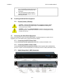
INSTALLATION MANUAL
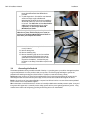
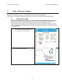
FOR SEA TEL 5012-33 KU-BAND
BROADBAND-AT-SEA VSAT ANTENNA SYSTEM
Sea Tel, Inc.
4030 Nelson Avenue
Concord, CA 94520
Tel: (925) 798-7979
Fax: (925) 798-7986
Web: http://www.cobham.com/seatel
October 22, 2012
Sea Tel Europe
Unit 1, Orion Industrial Centre
Wide Lane, Swaythling
Southampton, UK S0 18 2HJ
Tel: 44 (0)23 80 671155
Fax: 44 (0)23 80 671166
Web: http://www.cobham.com/seatel
Sea Tel Inc is also doing business as Cobham Antenna Systems
Document. No. 138222 Revision A
These commodities, technology or software were exported from the United States in
accordance with the Export Administration Regulations. Diversion contrary to U.S. law is
prohibited.
Sea Tel Marine Stabilized Antenna systems are manufactured in the United States of America.
Sea Tel is an ISO 9001:2008 registered company.
Certificate Number 13690 issued March 14, 2011.
R&TTE
CE
The Series 12 Maritime Satellite Earth Station complies with the requirements of directive
1999/5/EC of the European Parliament and of the Council of 9 March 1999 on Radio
equipment and Telecommunication Terminal Equipment. A copy of the R&TTE Declaration of
Conformity for this equipment is contained in this manual.
The Sea Tel Series 12 antennas will meet the off-axis EIRP spectral density envelope set forth in FCC 47 C.F.R. §
25.222(a)(1)(i) when the input power density limitations, listed in our FCC Declaration, are met..
These antenna systems also contain FCC compliant supervisory software to continuously monitor the pedestal
pointing accuracy and use it to control the “Transmit Mute” function of the satellite modem to satisfy the
provisions of FCC 47 C.F.R. § 25.222(a)(l)(iii).
Copyright Notice
Copyright © 2012 Sea Tel Inc All Rights Reserved. The information contained in this document is proprietary to Sea Tel,
Inc.. This document may not be reproduced or distributed in any form without prior written consent of Sea Tel, Inc. The
information in this document is subject to change without notice. Sea Tel Inc, is also doing business as Cobham Antenna
Systems.
This document has been registered with the U.S. Copyright Office.
Revision History
REV
ECO#
Date
Description
By
A
A1
9912
N/A
August 28, 2012
September 28, 2012
Production Release
Updated to 5012-91 and remove Green Passport pages.
MDN
MDN
ii
RTT&E Declaration Page
Testing Being Conducted
iii
FCC Declaration
Testing Being Conducted
iv
Table of Contents
1.
2.
3.
5012-33 Installation Manual
SERIES 12 KU-BAND SYSTEM CONFIGURATION(S)........................................................................................................... 1-1
1.1. SYSTEM CABLES ............................................................................................................................................................................................. 1-1
1.2. OTHER INPUTS TO THE SYSTEM .................................................................................................................................................................. 1-1
1.3. SIMPLIFIED BLOCK DIAGRAM OF A SERIES 12 KU-BAND SYSTEM........................................................................................................ 1-1
1.4. DUAL ANTENNA CONFIGURATION ............................................................................................................................................................. 1-2
1.5. OPEN ANTENNA-MODEM INTERFACE PROTOCOL (OPENAMIP™) SPECIFICATION:........................................................................ 1-3
1.5.1. Overview: ........................................................................................................................................................................................1-3
1.5.2. Interface requirements: .........................................................................................................................................................1-3
1.5.3. Utilized OpenAMIPTM Commands: ...................................................................................................................................1-4
SITE SURVEY .................................................................................................................................................................................................. 2-1
2.1. SITE SELECTION ABOARD THE SHIP .......................................................................................................................................................... 2-1
2.2. ANTENNA SHADOWING (BLOCKAGE) AND RF INTERFERENCE .............................................................................................................. 2-1
2.3. MOUNTING FOUNDATION ........................................................................................................................................................................... 2-2
2.3.1. Mounting on Deck or Deckhouse......................................................................................................................................2-2
2.3.2. ADE Mounting Considerations ...........................................................................................................................................2-2
2.3.3. Sizing of the support pedestal ............................................................................................................................................2-2
2.4. MOUNTING HEIGHT ...................................................................................................................................................................................... 2-3
2.5. MAST CONFIGURATIONS ............................................................................................................................................................................. 2-3
2.5.1. Vertical Masts ..............................................................................................................................................................................2-4
2.5.2. Raked Masts..................................................................................................................................................................................2-4
2.5.3. Girder Masts .................................................................................................................................................................................2-4
2.5.4. Truss Mast .....................................................................................................................................................................................2-5
2.6. SAFE ACCESS TO THE ADE .......................................................................................................................................................................... 2-5
2.7. BELOW DECKS EQUIPMENT LOCATION ..................................................................................................................................................... 2-5
2.8. CABLES ............................................................................................................................................................................................................. 2-5
2.8.1. ADE/BDE Coaxial Cables........................................................................................................................................................2-6
2.8.2. Antenna Power Cable ..............................................................................................................................................................2-6
2.8.3. Air Conditioner Power Cable ...............................................................................................................................................2-6
2.8.4. ACU Power Cable/Outlet ........................................................................................................................................................2-6
2.8.5. Gyro Compass Cable ................................................................................................................................................................2-6
2.9. GROUNDING.................................................................................................................................................................................................... 2-7
INSTALLATION ............................................................................................................................................................................................. 3-1
3.1. UNPACKING AND INSPECTION .................................................................................................................................................................... 3-1
3.2. ASSEMBLY NOTES AND WARNINGS ........................................................................................................................................................... 3-1
3.3. INSTALLING THE ADE ................................................................................................................................................................................... 3-2
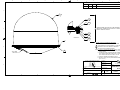
3.3.1. Prepare the 50”, 60”, 66” or 76” Radome Assembly ................................................................................................3-2
3.3.2. Installing the 50, 60 or 66” Radome Assembly..........................................................................................................3-3
3.4. GROUNDING THE PEDESTAL ......................................................................................................................................................................... 3-6
3.5. REMOVING THE SHIPPING/STOW RESTRAINTS PRIOR TO POWER-UP .............................................................................................. 3-7
3.5.1. Removing the AZ Shipping/Stow Restraint ..................................................................................................................3-7
3.5.2. Removing the EL Shipping/Stow Restraint ...................................................................................................................3-8
3.5.3. Removing the CL Shipping/Stow Restraint ................................................................................................................3-10
3.6. INSTALLING THE BELOW DECKS EQUIPMENT. ........................................................................................................................................3-11
3.6.1. General Cautions & Warnings ..........................................................................................................................................3-11
3.7. CONNECTING THE BELOW DECKS EQUIPMENT ......................................................................................................................................3-11
3.7.1. Connecting the ADE AC Power Cable..........................................................................................................................3-11
3.7.2. Connecting the BDE AC Power Cables........................................................................................................................3-11
3.7.3. Media Xchange Point™ (MXP) Connections .............................................................................................................3-11
v
5012-33 Installation Manual
Table of Contents
3.7.4. Other BDE connections ...................................................................................................................................................... 3-12
FINAL CHECKS.............................................................................................................................................................................................. 3-12
3.8.1. Visual/Electrical inspection ............................................................................................................................................... 3-12
3.8.2. Electrical - Double check wiring connections ......................................................................................................... 3-12
3.9. SETUP - MEDIA XCHANGE POINT™ (MXP) ......................................................................................................................................... 3-13
4. CONFIGURING A COMPUTER FOR THE MXP .......................................................................................................................... 4-1
5. SETUP – SHIP’S GYRO COMPASS ..................................................................................................................................................... 5-1
5.1. SETTING THE GYRO TYPE.............................................................................................................................................................................. 5-1
5.2. IF THERE IS NO SHIPS GYRO COMPASS..................................................................................................................................................... 5-2
6. SETUP – SATELLITE CONFIGURATION ....................................................................................................................................... 6-1
7. SETUP – HOME FLAG ................................................................................................................................................................................ 7-1
7.1. YOU FOUND A LARGE AZ TRIM VALUE: ................................................................................................................................................... 7-1
7.1.1. You Observe “Home” Pointing is LEFT of the Bow-line:......................................................................................... 7-2
7.1.2. You Observe “Home” Pointing is RIGHT of the Bow-line: ..................................................................................... 7-2
7.1.3. Entering a large value as Home Flag .............................................................................................................................. 7-3
7.1.1. Entering a small value as AZ TRIM .................................................................................................................................. 7-4
8. SETUP – BLOCKAGE ZONES ................................................................................................................................................................. 8-1
9. SETUP – CALIBRATING TARGETING ............................................................................................................................................ 9-1
9.1. AUTO TRIM ................................................................................................................................................................................................. 9-1
9.2. MANUALLY CALIBRATING TARGETING ...................................................................................................................................................... 9-3
10. QUICK START OPERATION ............................................................................................................................................................... 10-1
10.1. IF SATELLITE SIGNAL IS FOUND AND NETWORK LOCK IS ACHIEVED: ................................................................................................ 10-1
10.2. IF NO SIGNAL IS FOUND: ............................................................................................................................................................................ 10-1
10.3. IF SATELLITE SIGNAL IS FOUND BUT NETWORK LOCK IS NOT ACHIEVED: ........................................................................................ 10-3
10.4. TO TARGET A DIFFERENT SATELLITE ........................................................................................................................................................ 10-4
11. OPTIMIZING CROSS-POL ISOLATION ...................................................................................................................................... 11-1
11.1. OPTIMIZING CROSS-POL ISOLATION ...................................................................................................................................................... 11-1
12. SERIES 12 KU-BAND TECHNICAL SPECIFICATIONS ..................................................................................................... 12-1
12.1. ANTENNA ASSEMBLY 5009 ..................................................................................................................................................................... 12-1
12.2. TX RADIO PACKAGE ( -33 SYSTEMS)..................................................................................................................................................... 12-1
12.3. BUC POWER SUPPLY .................................................................................................................................................................................. 12-1
12.4. SMW QUAD BAND LNB ........................................................................................................................................................................... 12-2
12.5. INTEGRATED CONTROL UNIT (ICU) ....................................................................................................................................................... 12-3
12.6. MOTOR DRIVER ENCLOSURE (MDE)....................................................................................................................................................... 12-3
12.7. STABILIZED ANTENNA PEDESTAL ASSEMBLY ........................................................................................................................................ 12-4
12.8. GPS (INTEGRATED ON PEDESTAL) ........................................................................................................................................................... 12-5
12.9. RADOME ASSEMBLY, 66” .......................................................................................................................................................................... 12-6
12.1. SERIES 12 ENVIRONMENTAL SPECIFICATIONS (ADE) ........................................................................................................................ 12-7
12.1.1. Environmental Conditions (ADE) ................................................................................................................................... 12-7
12.1.2. Chemically Active Substances......................................................................................................................................... 12-7
12.1.3. Mechanical Conditions........................................................................................................................................................ 12-7
12.1.4. Transit Conditions.................................................................................................................................................................. 12-8
12.2. MEDIA XCHANGE POINT ™........................................................................................................................................................................ 12-8
12.2.1. Ship's Terminal Interface (MXP) .................................................................................................................................... 12-8
12.2.2. MXP Box Rear Panel Connections................................................................................................................................. 12-9
12.2.3. Integrated SCPC Receiver ................................................................................................................................................. 12-9
12.2.4. Control Interface .................................................................................................................................................................12-10
12.2.5. SW1 Local Band Select Output .....................................................................................................................................12-10
3.8.
vi
Table of Contents
5012-33 Installation Manual
12.2.6. SW2 Blockage/ TX Mute Output .................................................................................................................................. 12-10
12.2.7. NMEA Interface ...................................................................................................................................................................12-10
12.2.8. ICU/Pedestal Power Supply ........................................................................................................................................... 12-11
12.2.9. BUC Power Supply ...............................................................................................................................................................12-11
12.3. BDE ENVIRONMENTAL CONDITIONS....................................................................................................................................................12-11
12.4. SYSTEM WEIGHT (ADE) .........................................................................................................................................................................12-11
12.5. POWER REQUIREMENTS ...........................................................................................................................................................................12-11
12.6. REGULATORY COMPLIANCE.....................................................................................................................................................................12-11
12.7. CABLES ........................................................................................................................................................................................................12-12
12.7.1. Antenna L-Band IF Coax Cables (Customer Furnished).................................................................................. 12-12
13. DRAWINGS ................................................................................................................................................................................................... 13-1
13.1. 5012-33 KU-BAND MODEL SPECIFIC DRAWINGS ............................................................................................................................13-1
vii
5012-33 Installation Manual
Table of Contents
This Page Intentionally Left Blank
viii
Series 12 Ku-Band System Configuration(s)
1.
5012-33 Installation Manual
Series 12 Ku-Band System Configuration(s)
The Series 12 Ku-Band Stabilized Antenna system is to be used for Transmit/Receive (TX/RX) satellite communications, it is
comprised of two major groups of equipment. These are the Above Decks Equipment (ADE) and the Below Decks Equipment
(BDE). There will also be interconnecting cables between the ADE & BDE and cables to provide other inputs to the system.
It is initially equipped for Ku-Band operation, however, later it may be upgraded to Ka-Band if desired (when the Ka-Band
services are available).
1.1.
System Cables
AC Power & Coaxial cables will be discussed in a separate chapter.
1.2.
Other Inputs to the System
Multi-conductor cables from Ships Gyro Compass, GPS, phone, fax and Computer equipment may also be connected
in the system.
1.3.
Simplified block diagram of a Series 12 Ku-Band system
Your Series 12 Ku-Band TXRX system consists of two major groups of equipment; an above-decks group and a belowdecks group. Each group is comprised of, but is not limited to, the items listed below. All equipment comprising the
Above Decks is incorporated inside the radome assembly and is integrated into a single operational entity. For inputs,
this system requires only an unobstructed line-of-sight view to the satellite, Gyro Compass input and AC electrical
power.
A. Above-Decks Equipment (all shown as the ADE) Group
• Stabilized antenna pedestal
• Antenna Reflector
• Feed Assembly with Cross-Pol and Co-Pol LNBs
• 8W Ku-Band Solid State Block Up-Converter (BUC)
• Radome Assembly
B. Below-Decks Equipment Group
• Media Xchange Point™ (MXP)
• Customer Furnished Equipment - Satellite Modem and other below decks equipment required for the
desired communications purposes (including LAN and VOIP equipment).
• Appropriate Coax, Ethernet, and telephone cables
1-1
5012-33 Installation Manual
1.4.
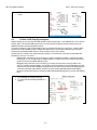
Series 12 Ku-Band System Configuration(s)
Dual Antenna Configuration
Sometimes, due to very large blockage conditions, you may need to install a dual antenna configuration to provide
uninterrupted services. Two full antenna systems are installed and the ACU control outputs are connected to an
arbitrator switch panel which then is connected to the below decks equipment. The connection scheme is required for
MXP “A” to be able to control Antenna “A” (and ONLY Antenna “A”) AND MXP “B” to be able to control Antenna “B”
(and ONLY Antenna “B”).
You will program the blockage zone(s) for each of the two antennas (refer to Setup – Blockage Zones). The blockage
output from each MXP is fed to the arbitrator. The blockage output is a transistor “short” to ground when the antenna
is within a programmed blockage zone and is an “open” when not blocked.
When one antenna is blocked, its blockage output will command the arbitrator panel to switch services to the modem
from that antenna to the other antenna. The arbitrator panel provides a logic latch to prevent excess switching when
the ship heading is yawing, therefore, causing if the antenna to be repeatedly blocked – unblocked – blocked.
1-2
Series 12 Ku-Band System Configuration(s)
1.5.
5012-33 Installation Manual
Open Antenna-Modem Interface Protocol (OpenAMIP™) Specification:
1.5.1.
Overview:
TM
OpenAMIP , an ASCII message based protocol invented and Trademarked by iDirect is a specification for
the interchange of information between an antenna controller and a satellite modem. This protocol allows
the satellite modem to command the MXP (via TCP port 2002) to seek a particular satellite as well as
allowing exchange of information necessary to permit the modem to initiate and maintain communication
via the antenna and the satellite. In general, OpenAMIPTM is not intended for any purpose except to permit a
modem and the MXP to perform synchronized automatic beam switching when using an iDirect Network. It
is NOT a status logging system or a diagnostic system. In addition, OpenAMIPTM is intended for a typical
installation whereby a specific satellite modem and Antenna system are properly configured to work
together. The protocol does not make specific provisions for auto-discovery or parameter negotiation. It is
still the responsibility of the installer to ensure that the parameters of both the satellite modem (proper
option files) and the MXP/PCU (setup parameters) are actually compatible for the intended satellite(s).
1.5.2.
Interface requirements:
1.5.2.1.
Hardware
Sea Tel Media Xchange Point (MXP)
Any Satellite modem manufacturer that is compatible with OpenAMIPTM
CAT5 Patch cable
1.5.2.2.
Software
Sea Tel MXP software version (latest).
1-3
5012-33 Installation Manual
Series 12 Ku-Band System Configuration(s)
Utilized OpenAMIPTM Commands:
1.5.3.
1.5.3.1.
Command
S f1 f2 f3
P c1 c2
H f1 f2
B f1 f2
F
Ai
L b1 b2
Wi
I s1 s2
Description
Satellite Longitude, 3 parameters:
Degrees E/W (-value equals West), Latitude Variance (Inclined
Orbit), Sat Skew Offset
Polarization, 2 parameters:
H,V,L,, or R
Tracking Frequency: 2 Parameters:
Center Frequency and Bandwidth in MHz
Down Conversion Offset: 2 parameters:
LNB (Receive) Local Oscillator and BUC (TX) L.O.
Find,
Target satellite using existing S, P,R, and H Parameters
Set keep alive in seconds (0 = off)
Modem Lock and free to transmit. 2 parameters:
b1 indicates Rx lock and b2 (not utilized) enables/disables Tx
Mute to BUC
GPS Update:
Sets GPS Update period in seconds (0 = Off)
Set modem vendor (s1) and device (s2) 2 parameters:
1.5.3.2.
Command
ai
i s1 s2
s b1 b2
w b1 f1 f2 t1
Antenna Commands:
Example
“S -20.1 1.0 3.5”
“P L R”
“H 1100.500 0.256”
“B 10750”
“A 5”
“L 1 1”
“W 300”
“I iDirect 5100”
Modem Commands:
Description
Set keep alive in seconds (0 = off)
Set Antenna Vendor (s1) and device (s2) 2 parameters:
Antenna Status: 2 parameters:
b1 is functional status and b2 is Tx allowed
Set GPS Position: 4 parameters:
b1 is validity flag, f1 is latitude, f2 is longitude, and t1 is
timestamp
1-4
Example
“a 5”
“i Sea Tel DAC-2202”
“s 1 1”
“w 1 38.222 122.123
0”
Site Survey
2.
5012-33 Installation Manual
Site Survey
The objective of the Site survey is to find the best place to mount the antenna & the below decks equipment, the length and
routing of the cables and any other items or materials that are required to install the system and identify any other issues that
must be resolved before or during the installation.
2.1.
Site Selection Aboard The Ship
The radome assembly should be installed at a location aboard ship where:
•
The antenna has a clear line-of-sight to view as much of the sky (horizon to zenith at all bearings) as is
practical.
•
X-Band (3cm) Navigational Radars:
•
•
The ADE should be mounted more than 0.6 meters/2 feet from 2kW (24 km) radars
•
The ADE should be mounted more than 2 meters/8 feet from 10kW (72 km) radars
•
The ADE should be mounted more than 4 meters/12 feet from 160kW (250km) radars
S-Band (10cm) Navigational Radars:
•
•
If the ADE is/has C-Band it should be mounted more than 4 meters/12 feet from the S-band Radar.
The ADE should not be mounted on the same plane as the ship's Radar, so that it is not directly in the Radar
beam path.
•
The ADE should be mounted more than 2.5 meters/8 feet from any high power MF/HF antennas (<400W).
•
The ADE should be mounted more than 4 meters/12 feet from any high power MF/HF antennas (1000W).
•
The ADE should also be mounted more than 4 meters/12 feet from any short range (VHF/UHF) antennae.
•
The ADE should be mounted more than 2.5 meters/8 feet away from any L-band satellite antenna.
•
The ADE should be mounted more than 3 meters/10 feet away from any magnetic compass installations.
•
The ADE should be mounted more than 2.5 meters/8 feet away from any GPS receiver antennae.
•
Another consideration for any satellite antenna mounting is multi-path signals (reflection of the satellite
signal off of nearby surfaces arriving out of phase with the direct signal from the satellite) to the antenna.
This is particularly a problem for the onboard GPS, and/or the GPS based Satellite Compass.
•
The Above Decks Equipment (ADE) and the Below Decks Equipment (BDE) should be positioned as close to
one another as possible. This is necessary to reduce the losses associated with long cable runs.
•
This mounting platform must also be robust enough to withstand the forces exerted by full rated wind load
on the radome.
•
The mounting location is robust enough that it will not flex or sway in ships motion and be sufficiently well
re-enforced to prevent flex and vibration forces from being exerted on the antenna and radome.
•
If the radome is to be mounted on a raised pedestal, it MUST have adequate size, wall thickness and gussets
to prevent flexing or swaying in ships motion. In simple terms it must be robust.
If these conditions cannot be entirely satisfied, the site selection will inevitably be a “best” compromise between the
various considerations.
2.2.
Antenna Shadowing (Blockage) and RF Interference
At the transmission frequencies of C and Ku band satellite antenna systems, any substantial structures in the way of
the beam path will cause significant degradation of the signal. Care should be taken to locate the ADE so that the ADE
has direct line-of-sight with the satellite without any structures in the beam path through the full 360 degree ships
turn. Wire rope stays, lifelines, small diameter handrails and other accessories may pass through the beam path in
limited numbers; however, even these relatively insignificant shadows can produce measurable signal loss at these
frequencies.
2-1
5012-33 Installation Manual
2.3.
Site Survey
Mounting Foundation
2.3.1.
Mounting on Deck or Deckhouse
While mounting the ADE on a mast is a common solution to elevate the ADE far enough above the various
obstructions which create signal blockages, sometimes the best mounting position is on a deck or deckhouse
top. These installations are inherently stiffer than a mast installation, if for no other reason than the design of
the deck/deckhouse structure is prescribed by the ship’s classification society. In the deck/deckhouse design
rules, the minimum plating and stiffener guidelines are chosen to preclude high local vibration amplitudes.
Most installations onto a deck or deckhouse structure will require a mounting pedestal to raise the ADE above
the deck for radome hatch access and to allow the full range of elevation (see ADE mounting considerations
above). Some care must be taken to ensure the mounting pedestal is properly aligned with the stiffeners
under the deck plating.
2.3.2.
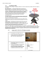
ADE Mounting Considerations
Mounting the radome directly on the deck, or platform
prevents access to the hatch in the base of the radome
unless an opening is designed into the mounting surface to
allow such entry. If there is no access to the hatch the only
way to service the antenna is to remove the radome top.
Two people are required to take the top off of the radome
without cracking or losing control of it, but even with two
people a gust of wind may cause them to lose control and
the radome top may be catastrophically damaged (see
repair information in the radome specifications).
If access to the hatch cannot be provided in the mounting
surface, provide a short ADE support pedestal to mount the
ADE on which is tall enough to allow access into the radome
via the hatch.
Ladder rungs must be provided on all mounting stanchions
greater than 3-4 feet tall to allow footing for personnel
safety when entering the hatch of the radome.
The recommended cable passage in the 50, 60 and 66 inch
radomes is through the bottom center of the radome base,
down through the ADE support pedestal, through the deck
and into the interior of the ship.
2.3.3.
Sizing of the support pedestal
The following should be taken into account when choosing the height of a mounting support stand:
1. The height of the pedestal should be kept as short as possible, taking into account recommendations
given in other Sea Tel Guidelines.
2. The minimum height of the pedestal above a flat deck or platform to allow access into the radome
for maintenance should be 0.6 meters (24 inches).
3. The connection of the ADE mounting plate to the stanchion and the connection of the pedestal to
the ship should be properly braced with triangular gussets (see graphic above). Care should be taken
to align the pedestal gussets to the ship’s stiffeners as much as possible. Doublers or other
reinforcing plates should be considered to distribute the forces when under-deck stiffeners are
inadequate.
4. The diameter of the pedestal stanchion shall not be smaller than 100 millimeters (4 inches). Where
the ADE base diameter exceeds 1.5 meters (60 inches), additional stanchions (quantity greater than
3) should be placed rather than a single large stanchion.
5. Shear and bending should be taken into account in sizing the ADE mounting plate and associated
gussets.
6. Shear and bending must be taken into account when sizing the pedestal to ship connection.
7. All welding should be full penetration welds –V-groove welds with additional fillet welds – with
throats equivalent to the thickness of the thinnest base material.
8. For an ADE mounted greater than 0.6 meters (24 inches) above the ship’s structure, at least one (1)
2-2
Site Survey
5012-33 Installation Manual
9.
2.4.
foot rung should be added. Additional rungs should be added for every 0.3 meter (12 inches) of
pedestal height above the ship’s structure.
For an ADE mounted greater than 3 meters (9 feet) above the ship’s structure, a fully enclosing cage
should be included in way of the access ladder, starting 2.3 meters (7 feet) above the ship’s
structure.
Mounting Height
The higher up you mount the antenna above the pivot point of the ship the higher the tangential acceleration (gforce) exerted on the antenna will be (see chart below).
When the g-force exerted on the antenna is light, antenna stabilization and overall performance will not be affected.
If the g-force exerted on the antenna is high enough (> 1 G), antenna stabilization and overall performance will be
affected.
If the g-force exerted on the antenna is excessive (1-2 Gs), the antenna will not maintain stabilization and may even
be physically damaged by the g-force.
2.5.
Mast Configurations
Sea Tel recommends the ADE be mounted on the ship in a location which has both a clear line-of-sight to the target
satellites in all potential azimuth/elevation ranges and sufficient support against vibration excitement. If possible,
mounting the ADE pedestal directly to ship deckhouse structures or other box stiffened structures is preferred.
However, in many cases, this imposes limits on the clear line-of-sight the antenna system has.
Often the solution for providing the full azimuth/elevation range the antenna needs is to mount the ADE on the ship’s
mast. Unfortunately, masts do not consider equipment masses in design and often have harmonic frequencies of their
own.
There are many designs of masts used on ships – masts are nearly as unique in design as the ship is – but the designs
often fall into just a few categories. These categories can be addressed in terms of typical responses and problems
with regards to vibration and mounting of ADE. The most common categories of masts are:
2-3
5012-33 Installation Manual
2.5.1.
Site Survey
Vertical Masts
Vertical masts are a very ancient and common mast design. In essence, it is the mast derived from the sailing
mast, adapted for mounting the ever-increasing array of antennae ships need to communicate with the
world. This drawing of a Vertical mast shows
preferred mounting of the ADE center-line above
the plane of the radar, or as an alternate with the
ADE mounted below the plane of the radar signal,
as reasonably good installations of a satellite
antenna ADE.
Vertical masts are most commonly still found on
cargo ships – they are simple, inelegant and
functional. They are also fairly stiff against
torsional reaction and lateral vibrations, as long as
the ADE is mounted on a stiff pedestal near the
vertical centerline of the mast. If centerline
mounting is impractical or otherwise prohibited,
the mast platform the ADE is mounted on should be checked for torsional vibration about the centerline of
the mast and the orthogonal centerline of the platform.
If the estimated natural frequency of the mast or platform is less than 35 Hertz, the mast or platform should
be stiffened by the addition of deeper gussets under the platform or behind the mast.
2.5.2.
Raked Masts
Raked masts are found on vessels where the style
or appearance of the entire vessel is important.
Again, the inclined mast is a direct descendant from
the masts of sailing ships – as ship owners wanted
their vessels to look more unique and less
utilitarian, they ‘raked’ the masts aft to make the
vessel appear capable of speed. This drawing
shows a raked mast, again with the preferred ADE
mounting above the radar and alternate with the
ADE below the radar.
Raked masts pose special problems in both
evaluating the mast for stiffness and mounting of
antennae. As can be seen in the drawing all
antennae must be mounted on platforms or other
horizontal structures in order to maintain the
vertical orientation of the antenna centerline. This
implies a secondary member which has a different
natural frequency than the raked mast natural frequency. In order to reduce the mass of these platforms,
they tend to be less stiff than the main box structure of the raked mast. Thus, they will have lower natural
frequencies than the raked mast itself. Unfortunately, the vibratory forces will act through the stiff structure
of the raked mast and excite these lighter platforms, to the detriment of the antenna.
2.5.3.
Girder Masts
Girder masts are large platforms atop a pair of
columns. Just like girder constructions in buildings,
they are relatively stiff athwart ship – in their
primary axis – but less stiff longitudinally and
torsionally. An example of a girder mast is shown in
this drawing, with the preferred ADE mounting
outboard and above the radar directly on one of the
columns and alternate with the ADE centered on
the girder above the plane of the radar.
The greatest weakness of girder masts is in torsion –
where the girder beam twists about its vertical
centerline axis. As with all mast designs discussed so far, mounting the antenna in line with the vertical
2-4
Site Survey
5012-33 Installation Manual
support structure will reduce the vibration tendencies. Mounting the antenna directly above the girder
columns provides ample support to the antenna pedestal and locates the antenna weight where it will
influence the natural frequency of the mast the least.
2.5.4.
Truss Mast
Truss masts are a variant on the girder mast
concept. Rather than a pair of columns supporting a
girder beam, the construction is a framework of
tubular members supporting a platform on which
the antennae and other equipment is mounted. A
typical truss mast is shown in this photograph.
Like a girder mast, truss masts are especially stiff in
the athwart ship direction. Unlike a girder mast, the
truss can be made to be nearly as stiff in the
longitudinal direction. Truss masts are particularly
difficult to estimate the natural frequency – since a
correct modeling includes both the truss structure
of the supports and the plate/diaphragm structure
of the platform. In general, though, the following
guidelines apply when determining the adequate
support for mounting an antenna on a truss mast:
1. Antenna ADE pedestal gussets should align
with platform stiffeners which are at least
200 millimeters in depth and 10 millimeters in thickness.
2. When possible, the antenna ADE pedestal column should align with a vertical truss support.
3. For every 100 Kilograms of ADE weight over 250 Kilograms, the depth of the platform stiffeners
should be increased by 50 millimeters and thickness by 2 millimeters.
Sea Tel does not have a recommended arrangement for a truss mast – the variability of truss mast designs
means that each installation needs to be evaluated separately.
2.6.
Safe Access to the ADE
Safe access to the ADE should be provided. Provisions of the ship’s Safety Management System with regard to men
aloft should be reviewed and agreed with all personnel prior to the installation. Installations greater than 3 meters
above the deck (or where the access starts at a deck less than 1 meter in width) without cages around the access
ladder shall be provided with means to latch a safety harness to a fixed horizontal bar or ring.
The access hatch for the ADE shall be oriented aft, or inboard, when practical. In any case, the orientation of the ADE
access hatch shall comply with the SMS guidelines onboard the ship. Nets and other safety rigging under the ADE
during servicing should be rigged to catch falling tools, components or fasteners.
2.7.
Below Decks Equipment Location
The Antenna Control Unit, Terminal Mounting Strip and Base Modem Panel are all standard 19” rack mount, therefore,
preferred installation of these items would be in such a rack. The ACU mounts from the front of the rack. The
Terminal Mounting Strip and Base Modem Panel mount on the rear of the rack.
The Satellite Modem, router, VIOP adapter(s), telephone equipment, fax machine, computers and any other associated
equipment should also be properly mounted for shipboard use.
Plans to allow access to the rear of the ACU should be considered.
2.8.
Cables
During the site survey, walk the path that the cables will be installed along. Pay particular attention to how cables will
be installed all along the path, what obstacles will have to have be routed around, difficulties that will be encountered
and the overall length of the cables. The ADE should be installed using good electrical practice. Sea Tel recommends
referring to IEC 60092-352 for specific guidance in choosing cables and installing cables onboard a ship. Within these
guidelines, Sea Tel will provide some very general information regarding the electrical installation.
In general, all cable shall be protected from chaffing and secured to a cableway. Cable runs on open deck or down a
mast shall be in metal conduit suitable for marine use. The conduit shall be blown through with dry air prior to passing
cable to ensure all debris has been cleared out of the conduit and again after passing the cable to ensure no trapped
2-5
5012-33 Installation Manual
Site Survey
moisture exists. The ends of the conduit shall be sealed with cable glands (preferred), mastic or low VOC silicon
sealant after the cables have been passed through.
Cables passing through bulkheads or decks shall be routed through approved weather tight glands.
2.8.1.
ADE/BDE Coaxial Cables
The first concern about the coaxial cables installed between the ADE & BDE is length. This length is used to
determine the loss of the various possible coax, Heliax or fiber-optic cables that might be used. You should
always provide the lowest loss cables to provide the strongest signal level into the satellite modem.
Signal cable shall be continuous from the connection within the ADE radome, through the structure of the
ship to the BDE. Splices, adapters or dummy connections will degrade the signal level and are discouraged.
Be careful of sharp bends that kink and damage the cable. Use a proper tubing bender for Heliax bends.
Penetrations in watertight bulkheads are very expensive, single cable, welded penetrations that must be
pressure tested.
Always use good quality connectors that are designed to fit properly on the cables you are using. Poor
quality connectors have higher loss, can allow noise into the cable , are easily damaged or fail prematurely.
In as much as is possible, don’t lay the coaxes on power cables. Try to have some separation from Inmarsat &
GPS cables that are also passing L-band frequencies or Radar cables that may inject pulse repetition noise –as
error bits - into your cables.
2.8.2.
Antenna Power Cable
Be cautious of length of the run, for voltage loss issues, and assure that the gauge of the wires is adequate for
the current that is expected to be drawn (plus margin). Antenna power is not required to be from a UPS
(same one that supplies power to the below decks equipment), but it is recommended.
Power cable shall comply with the provisions of IEC 60092-350 and -351 in so far as practicable. Power
cable may be routed through the same conduit as the signal cable from the junction box to the base of the
ADE. Power cables shall pass through separate radome penetrations from the signal cable.
The power cable shall be continuous from the UPS (or closest circuit breaker) to the ADE connections within
the radome. The power circuits shall be arranged so that ‘active,’ ‘common’ and ‘neutral’ (ground) legs are all
made or broken simultaneously. All circuit legs shall be carried in the same cable jacket.
2.8.3.
Air Conditioner Power Cable
If your system includes a marine air conditioner (available with the 81 inch radome ONLY), run an AC power
cable to it from a breaker, preferably from a different phase of the electrical system than supplies power to
the ADE & BDE. Be EXTREMELY cautious of length of the run for voltage loss and gauge of the wires for the
current that is expected to be drawn.
Power cable shall comply with the provisions of IEC 60092-350 and -351 in so far as practicable. Power
cable may be routed through the same conduit as the signal cable from the junction box to the base of the
ADE. Power cables shall pass through separate radome penetrations from the signal cable.
The power cable shall be continuous from the closest circuit breaker to the ADE connections within the
radome. The power circuits shall be arranged so that ‘active,’ ‘common’ and ‘neutral’ (ground) legs are all
made or broken simultaneously. All circuit legs shall be carried in the same cable jacket.
2.8.4.
ACU Power Cable/Outlet
The AC power for the ACU and other below decks equipment is not required to be from a UPS (same one that
supplies power to the ADE), but it is recommended.
Power cable shall comply with the provisions of IEC 60092-350 and -351 in so far as practicable.
2.8.5.
Gyro Compass Cable
Use good quality shielded cable (twisted pairs, individually foil wrapped, outer foil with braid overall is best)
You only need 2-wire for NMEA signal, 4-wire for Step-By-Step and 5-wire for Synchro … always use shielded
cable. Be cautious of length and gauge of the run for voltage loss issues.
2-6
Site Survey
2.9.
5012-33 Installation Manual
Grounding
All metal parts of the ADE shall be grounded to bare metal at the mounting pedestal. Grounding straps from the base
of the ADE to a dedicated lug on the mounting pedestal are preferred, but grounding may also be accomplished by
exposing bare metal under all mounting bolts prior to final tightening. Preservation of the bare metal should be done
to prevent loss of ground.
Grounding should be ensured throughout the entire mounting to the hull. While it is presumed the deckhouse is
permanently bonded and grounded to the hull, in cases where the deckhouse and hull are of different materials a
check of an independent ground bonding strap should be made. Masts should be confirmed to be grounded to the
deckhouse or hull.
2-7
5012-33 Installation Manual
Site Survey
This Page Intentionally Left Blank
2-8
Installation
3.
5012-33 Installation Manual
Installation
Your antenna pedestal comes completely assembled in its radome. This section contains instructions for unpacking, final
assembly and installation of the equipment. It is highly recommended that installation of the system be performed by trained
technicians.
The installation instructions for your system are below.
3.1.
Unpacking and Inspection
Exercise caution when unpacking the equipment.
1. Unpack the crates. Carefully inspect the radome surface for evidence of shipping damage.
2. Unpack all the boxes.
3. Inspect everything to assure that all materials have been received and are in good condition.
3.2.
Assembly Notes and Warnings
NOTE: All nuts and bolts should be assembled using the appropriate Loctite thread-locker
product number for the thread size of the hardware.
Loctite # Description
222
Low strength for small fasteners.
242
Medium strength
638
High strength for Motor Shafts & Sprockets.
2760
Permanent strength for up to 1” diameter fasteners.
290
Wicking, High strength for fasteners which are already
assembled.
WARNING: Assure that all nut & bolt assemblies are tightened according to the
tightening torque values listed below:
SAE Bolt Size
Inch Pounds
Metric Bolt Size
Kg-cm
1/4-20
75
M6
75.3
5/l6-18
132
M8
150
3/8-16
236
M10
270
1/2-13
517
M12
430
WARNING: Hoisting with other than a webbed four-part sling may result in catastrophic
crushing of the radome. Refer to the specifications and drawings for the fully assembled
weight of your model Antenna/Radome and assure that equipment used to lift/hoist this
system is rated accordingly.
CAUTION: The antenna/radome assembly is very light for its size and is subject to large
swaying motions if hoisted under windy conditions. Always ensure that tag lines, attached
to the radome base frame, are attended while the antenna assembly is being hoisted to its
assigned location aboard ship.
3-1
5012-33 Installation Manual
3.3.
Installation
Installing the ADE
The antenna pedestal is shipped completely assembled in its radome. Please refer to the entire Site Survey chapter of
this manual.
Base Hatch Access - Mounting the radome directly on the deck, or
platform prevents access to the hatch in the base of the radome unless an
opening is designed into the mounting surface to allow such entry. If there is
no access to the hatch the only way to service the antenna is to remove the
radome top. Two people are required to take the top off of the radome
without cracking or losing control of it, but even with two people a gust of
wind may cause them to lose control and the radome top may be
catastrophically damaged (see repair information in the radome
specifications) or lost.
If access to the hatch cannot be provided in the mounting surface, provide a
short ADE mounting stanchion to mount the ADE on which is tall enough to
allow access into the radome via the hatch.
Ladder rungs must be provided on all mounting stanchions greater than 3-4
feet tall to allow footing for personnel safety when entering the hatch of the
radome.
Cable Passage - The radome base is designed with a bottom center cable
passage and Roxtec® Multidiameter® blocks for cable strain relief. The
recommended cable passage in the 50, 60, 61 and 66 inch radomes is through
the bottom center of the radome base, down through the ADE mounting
stanchion, through the deck and into the interior of the ship.
Bottom center cable passage is recommended, however, a strain relief kit is provided with the system if off-center
cable entry is required. Note: Strain relief installation procedure, provided in the Drawings chapter, MUST
be followed to assure that the cored holes are properly sealed to prevent moisture absorption and delamination of the radome base.
3.3.1.
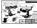
Prepare the 50”, 60”, 66” or 76” Radome Assembly
1.
2.
3.
Remove the side walls of the Radome crate.
Lift the pallet using a forklift and/or jacks.
From the under side of the pallet, remove the
4 shipping bolts which attach the ADE to its’
pallet. Discard this shipping hardware.
4.
Remove four equally spaced bolts around the
radome flange. Save these nuts and bolts to
be re-installed later.
Install four lifting eyebolts in the vacant holes
in the flange of the radome.. (Hardware
provided in the radome installation kit). Keep
the original perimeter bolt hardware to be reinstalled after the ADE has been installed.
5.
3-2
Installation
5012-33 Installation Manual
6.
7.
8.
3.3.2.
Attach shackles and four part web lifting sling
arrangement to the eyebolts.
Attach a suitable length tagline to one of the
eyebolts.
After hoisted into place the lifting eyes are to
be removed & replaced with the stainless
hardware that was removed in step 4 (the
eyes are galvanized with bare thread that will
rust if left exposed to the weather).
Installing the 50, 60 or 66” Radome Assembly
The antenna pedestal is shipped completely assembled in its radome.
1.
2.
3.
4.
5.
6.
Man the tag line(s).
Hoist the antenna assembly off the shipping pallet,
by means of a suitably sized crane or derrick, to allow
access to bottom of radome assembly.
Open the hatch by pressing the round release button
in the center of the black latches and gently push the
hatch up into the radome. Place the hatch door (gel
coat surface up) inside the radome on the far side of
the antenna pedestal.
Inspect the pedestal assembly and reflector for signs
of shipping damage.
Peel the paper off of the mounting pad (provided in
the radome installation kit) to expose the sticky side
of the pad, align it to the mounting holes and press it
in place on the underside of the radome base.
Using Loctite 271, install the 4 mounting bolts
(provided in radome mounting kit) into the radome
base.
3-3
5012-33 Installation Manual
7.
Installation
Remove the hardware in the cable mounting frame.
8.
Lift the cable mounting frame out from the cable
passage channel.
NOTE: If the bottom center cable passage will NOT
be used, it is recommended that the strain reliefs be
installed in place of this cable mounting frame. Other
locations around the radome base are MUCH thicker,
requiring longer strain reliefs than the ones provided
by Sea Tel. Refer to the strain relief installation
procedure provided in the Drawings chapter of this
manual.
9. Man the tag line and have the crane continue lifting
the ADE up and hover above the mounting site on
the ship.
10. Carefully route AC Power, ground strap/cable (see
Grounding info below) and IF coax cables through
the cable passage in the bottom center of the
radome base and through the cable channel under
the lower base plate of antenna.
NOTE: Suitable strain relief should be provided below
the mounting surface to prevent the cables from
being kinked where the cables exit the bottom of the
radome.
11. Allow enough service loop to terminate these cables
to the circuit breaker assembly and connector
bracket respectively (see cable termination
information below).
HINT: It may be easier to connect, or tie-wrap, the
coaxes and power cable temporarily.
12. Lower radome assembly into the mounting holes,
positioned with the BOW reference of the radome as
close to parallel with centerline of the ship as
possible (any variation from actual alignment can be
electrically calibrated if needed).
13. Using Loctite 271, install the 4 fender washers and
hex nuts (provided in the radome installation kit),
from the underside of the mounting surface, to affix
the radome to the mounting surface. Tighten to
torque spec.
3-4
Installation
5012-33 Installation Manual
14. Remove the clamp bar and Roxtec® Multidiameter®
blocks from their cable mounting frame in the cable
passage channel.
15. Remove the rubber bar from the top of the Roxtec®
Multidiameter® blocks.
16. Remove the Roxtec® Multidiameter® blocks from
the cable mounting frame.
17. Pass the coaxes and power cable through the cable
mounting frame.
HINT: Again, It may be easier to connect, or tie-wrap,
the coaxes and power cable temporarily.
18. Re-install the cable mounting frame onto cable
passage channel using the four screws and flat
washers that were removed in step 7 above. .
19. Peel layers out of the upper and lower Roxtec®
Multidiameter® blocks to provide an opening in the
block that is just smaller than the outer diameter of
the cable that will pass through it. When
compressed the block should provide clamping force
on the cable and prevent it from moving in the block.
3-5
5012-33 Installation Manual
Installation
20. Two cables may be passed through each of the
Roxtec® Multidiameter® CM-20w40 blocks
provided.
21. If cables larger than 1.65cm/0.65in outer diameter
will be used, larger single-cable Roxtec®
Multidiameter CM-40 10-32 blocks are available to
allow three cables of up to3.25cm/1.28in diameter
to be used. The rubber bar and the three doublecable Roxtec® Multidiameter blocks will be
replaced by the three larger Roxtec®
Multidiameter blocks.
HINT: It may be helpful to put the clamp bar and
rubber bar in place (held loosely by one screw) to
hold some of the Roxtec® Multidiameter blocks in
place while you complete the others.
22. Re-install the clamp bar using the hardware removed
in step 14 above.
23. Remove the tag lines.
24. Remove the lifting sling.
25. Remove the 4 lifting eye nuts and re-install the
original perimeter bolt hardware (the eyes are
galvanized with bare thread that will rust if left
exposed to the weather). Save the lifting eye
hardware in case lifting of the ADE is required in the
future.
3.4.
Grounding the Pedestal
The antenna pedestal must be grounded to the hull of the ship. A grounding point is provided on the upper base plate
to ground the pedestal. You must provide a cable, or strap, that is of sufficient gauge and length to ground the
pedestal to the nearest grounding point of the hull (this is usually on or near the mounting surface).
Solid strap is the conductor of choice for low impedance RF ground connections because the RF currents tend to
flow along the outer surface and the strap has a large, smooth, surface area to take full advantage of this effect.
Braid is the conductor of choice where flexibility is required. Sea Tel uses braid to cross axes of the antenna pedestal
and to connect various subassemblies together.
Wire is the easiest to install, the easiest to connect and is readily available with a weather protective jacket. 4 awg and
6 awg bare solid copper wire is commonly used as safety grounds and very basic lightning protection grounds. 2 awg
stranded wire is often used for lightning grounding and bonding and it much more flexible.
3-6
Installation
5012-33 Installation Manual
1.
Provide a grounding strap/cable (of
adequate gauge for the length) to
provide a good ground drain for the
antenna pedestal. This cable/strap
must also be insulated where it may
be exposed to weather.
NOTE: Minimum gauge should not be
smaller than 10 AWG, even for a short cable
run.
2. Route the ground cable/strap into
the radome with the coax and
power cables.
3. Connect grounding strap/cable to
the burnished ground point on the
upper base plate.
4. Route the ground strap/cable
through one of the Roxtec®
Multidiameter® blocks with the
other power and coax cables.
5. Connect the other end of the
grounding strap/cable to a
burnished ground point on, or near,
the mounting surface. Bi-metal
coupling plate may be required to
get good electrical coupling.
Protective coating should be
applied to prevent the grounding
point from rusting or corroding.
3.5.
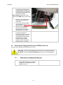
Removing the Shipping/Stow Restraints PRIOR to Power-Up
The order in which the restraints are removed is not critical.
CAUTION: There are three shipping/Stow restraints on this antenna pedestal
that MUST be removed, before energizing the antenna, for normal operation.
3.5.1.
1.
Removing the AZ Shipping/Stow Restraint
The AZ Shipping/Stow restraint is formed by a
pin bolt that is lowered into a channel in a
stowage block on the upper plate of the
pedestal (as shown).
3-7
5012-33 Installation Manual
Installation
2.
To un-stow the antenna, remove the pin bolt
from the LOCK position.
3.
Install the pin bolt into the STOW hole and
tighten. This assures that it does not get lost
and will be ready for re-use if the antenna
needs to be stowed again at a later date.
Verify that the antenna is able to rotate freely
in Azimuth.
4.
3.5.2.
1.
2.
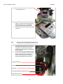
Removing the EL Shipping/Stow Restraint
The EL Shipping/Stow restraint is formed by a
Stow pin-bolt mounted through a bracket and
is engaged into a hole/slot in the elevation
driven sprocket when the dish is at zenith (90
degrees elevation).
In the stowed position the hardware from left
to right is Stow pin-bolt head, washer, bracket,
washer, hex nut, hex nut so that the pin
section of the Stow pin-bolt is inserted into
the hole in the elevation driven sprocket.
EL Stow Pin-Bolt head
Bracket
2 Hex Nuts
Pin inserted into Elevation Driven Sprocket
Elevation Driven Sprocket
3-8
Installation
5012-33 Installation Manual
3.
4.
5.
6.
7.
To un-restrain the elevation axis of the
antenna, unthread the two hex nuts. Using a
¾” open end wrench, remove the hex nuts
and washer from the stow pin-bolt.
Remove the stow pin-bolt from the bracket.
Remove the washer from the stow pin-bolt
and thread one of the 2 hex nuts onto the
bolt and tighten.
Put one of the washers onto the stow pin-bolt
and insert it into the bracket toward the
elevation driven sprocket.
Put the other washer, and then the other hex
nut onto the bolt.
3-9
5012-33 Installation Manual
8.
9.
3.5.3.
1.
Installation
Tighten the hex nut to prevent the hardware
from loosening while in the un-stowed
configuration.
Verify that the antenna rotates freely through
its full elevation range of motion.
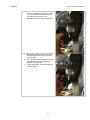
Removing the CL Shipping/Stow Restraint
The CL Shipping/Stow restraint is formed by a
red locking bar with adjustable bumpers at
each end of the bar. This mechanism is
placed under the cross-level beam to lock it in
place.
Cross-Level Beam
CL Shipping/Stow bar
Adjustable CL Locking Bumpers (only one end shown)
2.
To un-restrain the cross-level axis of the
antenna use a 7/16“ open end wrench to
loosen the nut on the top side of the locking
bar (either end of the bar).
3.
Remove the bottom nut off of that adjustable
bumper.
Remove the adjustable bumper from the
locking bar.
4.
3-10
Installation
5012-33 Installation Manual
5.
6.
3.6.
Extract the locking bar from the underside of
the cross-level beam and retain these parts for
later re-use if it becomes necessary to stow
the antenna.
Verify that the antenna rotates (tilts left &
right from level) freely through its full crosslevel range of motion.
Installing the Below Decks Equipment.
3.6.1.
General Cautions & Warnings
CAUTION - Electrical Shock Potentials exist on the Gyro Compass output
lines. Assure that the Gyro Compass output is turned OFF when handling and
connecting wiring to the MXP.
CAUTION - Allow only an authorized dealer to install or service the your Sea Tel
System components. Unauthorized installation or service can be dangerous and may
invalidate the warranty.
3.7.
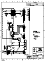
Connecting the Below Decks Equipment
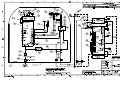
Connect this equipment as shown in the System Block Diagram. Install the equipment in a standard 19 inch
equipment rack or other suitable location. Optional slide rails are available.
3.7.1.
Connecting the ADE AC Power Cable
Connect the AC Power cable that supplies power to the ADE to a suitably rated breaker or UPS.
3.7.2.
Connecting the BDE AC Power Cables
Connect the AC Power cables that supply power to the Below Decks Equipment (MXP, Satellite Modem,
phone, fax, computer and all other equipment) to an outlet strip fed from a suitably rated breaker or UPS.
3.7.3.
Media Xchange Point™ (MXP) Connections
3-11
5012-33 Installation Manual
3.7.3.1.
Installation
Ships Mains
Connect the desired power cord from the rear panel of the MXP to power sourse (UPS power
recommended).
3.7.3.2.
J1 (Modem RX)
Connect this RXIF Output to the satellite modem RX Input.
3.7.3.3.
J2 Antenna RX
Connect this RXIF Input from the antenna to the MXP.
3.7.3.4.
Ethernet 4 Port 10/100 switch
Ethernet connections to computer, satellite modem LAN devices as desired.
3.7.3.5.
Fiber Interface
SFP Gigabit Ethernet connection.
3.7.3.6.
Mini-USB Computer M&C Connection
Mini-USB M&C connection, if desired.
3.7.3.7.
USB
Not connected - -Future development.
3.7.3.8.
J9 A/B Serial
Computer RJ-45 Serial M&C connection.
3.7.3.9.
J10C Modem
RJ-45 Serial M&C connection to Satellite Modem Console Port.
3.7.3.10.
J10D OBM
RJ-45 Serial M&C connection to Out of Band Management equipment, if used.
3.7.3.11.
J11 Gyro
Gyro SBS or Synchro connections.
3.7.3.12.
J13 NMEA 0183
NMEA 0183 I/O connections..
3.7.3.13.
J12 Aux 232
Auxiliary wired RS-232 connection.
3.7.3.14.
J14 Aux 232
Not connected - -Future development.
3.7.3.15.
J15 NMEA 2000
NMEA 2000 I/O connection..
3.7.4.
Other BDE connections
Connect your other Below Decks Equipment (ie, telephone, fax machine and computer equipment) to
complete your configuration.
3.8.Final Checks
3.8.1.
Visual/Electrical inspection
Do a visual inspection of your work to assure that everything is connected properly and all cables/wires are
secured.
3.8.2.
Electrical - Double check wiring connections
Double check all your connections to assure that it is safe to energize the equipment.
3-12
Installation
5012-33 Installation Manual
3.9.
Setup - Media Xchange Point™ (MXP)
Now that you have installed the hardware, you will need to setup, calibrate and commission the antenna.
You may also need to load/update the modem option file, which is not part of the scope of this manual, contact the
airtime provider NOC for guidance.
At the very least, you will need to set up the antenna system for:
•
Connect & configure a ships computer for accessing the MXP.
•
The gyro compass signal being provided by the ship.
•
Check/Set Home Flag.
•
Set up Blockage zone(s) as needed.
•
Set up / configure all satellites that the system might use as the ship travels, even if there is only one. If your
system will be using iDirect OpenAMIP you will not need to create satellite configurations.
•
Acquire the desired satellite.
•
Optimize targeting (Auto or manual trim).
•
Arrange for commissioning & cross-pol isolation testing with the NOC.
•
Conduct cross-pol isolation testing with the NOC.
•
Conduct other commissioning testing with the NOC (ie P1dB compression point).
•
If this is a Dual Antenna installation configuration, you will have to balance the TX levels of the two antennas
while online with the NOC (refer to procedure in the Dual Antenna Arbitrator manual).
•
It is strongly recommended that you download, and save, the system INI file (contains all of the system
parameters for the ICU and the MXP). Save this file in a convenient location on your computer.
3-13
5012-33 Installation Manual
Installation
This Page Intentionally Left Blank
3-14
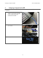
Configuring a Computer for the MXP
4.
5012-33 Installation Manual
Configuring a Computer for the MXP
The first thing you need to do is to configure your computer so that it will display the MXP screens. Follow these instructions to
accomplish that.
1.
Connect a LAN cable to the back of your
computer. If you are connecting into a LAN,
instead of a single computer, you will need to
provide a connection from your LAN
router/hub/switch to the MXP.
2.
Connect the other end of the LAN cable to the
back of the MXP.
3.
Power on the MXP.
4-1
5012-33 Installation Manual
4.
Configuring a Computer for the MXP
From your computer desktop, click the Control
Panel button.
NOTE: The following displayed screen captures are form
Window 7 OS, Your screens may differ, refer to your PC
manual for changing network adapter settings.
5.
Click on “View network status and tasks”.
6.
Click “Change adapter settings”.
7.
Click on “Local Area Connection.”
4-2
Configuring a Computer for the MXP
8.
Click on “Properties”.
9.
Double-Click on “Internet Protocol Version 4
(IPv4)”.
5012-33 Installation Manual
10. Click on “Use the following IP address:
4-3
5012-33 Installation Manual
Configuring a Computer for the MXP
11. In the IP Address boxes, enter “10.1.1.102” (This
is for the IP address of your computer).
NOTE: You could use 101, 102, 103, etc. as long as it is
not the same as the address of the MXP, which is
“10.1.1.100” (default).
12. On the second line, enter Subnet Mask of
“255.255.255.0”.
13. Then click the “OK” button.
14. Back at the Local Area Connection Properties
screen, click the “OK” button.
15. Click the “Close” button.
4-4
Configuring a Computer for the MXP
5012-33 Installation Manual
16. Close the Control Panel.
17. Open your browser, and enter the URL:
“10.1.1.100”.
18. At the log in screen enter the user name (Dealer,
SysAdmin, or User). Contact Sea Tel Service for
the password.
19. After you log in you will see the System Status
screen
4-5
5012-33 Installation Manual
Configuring a Computer for the MXP
This Page Intentionally Left Blank
4-6
Setup – Ship’s Gyro Compass
5.
5012-33 Installation Manual
Setup – Ship’s Gyro Compass
The Ships Gyro Compass connection provides true heading (heading of the ship relative to true North) input to the system. This
allows the ICU to target the antenna to a “true” Azimuth position to acquire any desired satellite.
After targeting, this input keeps the antenna stabilized in Azimuth (keeps it pointed at the targeted satellite Azimuth).
5.1.
Setting the Gyro Type
The GYRO TYPE parameter selects the type of gyro compass interface signal, the appropriate hardware connections,
and the ratio of the expected input signal for ship turning compensation. Default GYRO TYPE parameter for all
systems is Step-By-Step so that the ICU will properly follow for Step-By-Step or NMEA gyro signals.
If the Ships Gyro Compass output is Synchro, or there is NO Gyro Compass, the GYRO TYPE parameter must be set
correctly to properly read and follow the Ships Gyro Compass signal that is being provided. To manually update the
Gyro Type parameter:
1.
2.
Go to the Communications Interface screen.
Click the Gyro Type drop down menu..
3.
Select the correct Gyro type.
5-1
5012-33 Installation Manual
4.
5.2.
Setup – Ship’s Gyro Compass
Click Save, at the bottom left area of the
screen.
If there is NO Ships Gyro Compass
Without heading input to the system the MXP will NOT be able to easily target, or stay stabilized ON, a “true” azimuth
pointing angle. This will make satellite acquisition much more difficult and the true azimuth value that any given
satellite should be at will not be displayed correctly.
This mode of operation is NOT recommended for ships or any other vessel that turns in the water. A better solution
would be to provide a Satellite Compass (multiple GPS Antenna device) to provide true heading input to the ACU.
These devices are readily available and are much less expensive than a Gyro Compass.
If there is NO Gyro Compass (ie on a large stationary rig which is anchored to the ocean floor) set the GYRO TYPE
parameter to “No Gyro” or to “Fixed”.
Fixed mode is used when you do not have a gyro compass, but the ship/vessel/rig is stationary at a fixed
heading that you can manually enter for satellite targeting. This allows you to use a standard (small) search
pattern and acquire the satellite relatively quickly.
No gyro mode is used when you do not have a gyro compass, the ship does turn and you will use “Sky
Search” to initially acquire the satellite. The Sky Search drives the antenna to the calculated elevation angle
and then drives azimuth CW 360 degrees, steps elevation up and then drives azimuth CCW 360 degrees and
continues to alternately steps elevation up/down and drives azimuth alternately CW/CCW 360 degrees.
Because of this large search area, acquiring the satellite will take MUCH longer than if you have valid heading
input.
1.
2.
Go to the Reflector Configuration page
To change: Set the Scan Rate parameter to 5
deg/sec.
5-2
Setup – Ship’s Gyro Compass
3.
5012-33 Installation Manual
Turn on SAT REF Mode. (It must be turned on.)
This combination of settings will cause “No Gyro” Search pattern to be use to find the desired satellite (refer to the
setup – Searching chapter).
5-3
5012-33 Installation Manual
Setup – Ship’s Gyro Compass
This Page Intentionally Left Blank
5-4
Setup – Satellite Configuration
6.
5012-33 Installation Manual
Setup – Satellite Configuration
If your system will be using iDirect OpenAMIP, you will not need to configure any satellites and can skip this chapter.
The values that these parameters are set to depends on the hardware configuration required for each satellite. Configure each
of the satellites that airtime services will be provided on so that any one of them can be selected, remotely or by the user
onboard. The satellite selection will in turn control the hardware on the antenna pedestal to select the correct TX & RX
hardware and the correct tracking settings.
Sea Tel provides quad-band LNBs as standard on the Series 12 Ku-Band antennas.
1.
2.
3.
4.
5.
Access the Satellite Configuration screen.
If no satellites have been configured, or
you need to add another, click Add
Satellite.
Enter a name for this satellite you are
creating.
Enter the Longitude position of this
satellite.
Select the satellite that your airtime
services will be provided on.
6.
Determining the IF Tracking Frequency (MHz)
The IF Tracking frequency parameter is a value entered into the MXP MHZ Sub-Menu. The value itself
may be provided by your air-time provider and the MHz value will be entered directly in this sub-menu.
Or, the RF downlink frequency of a specific carrier on the desired satellite can be obtained from a satellite
website and calculated by using the formula RF- LO = IF. When you take the Satellite Transponder
Downlink RF value and subtract the LNB’s Local Oscillator (LO) Value, the resultant value will equal the
Intermediate Frequency (IF). It is this IF value that will be entered into the MXP for tracking purposes.
The MHz and KHz are entered as a single value.
Example: Assuming an LNB LO value of 11.25GHz: We want to track a satellite downlink carrier at
12268.250 MHz.
12268.250 MHz – 11250.000 MHz = 1018.250 MHz IF
7.
Enter the entire six digits of the
“megahertz and kilohertz” is simply
entered as one value in the Frequency
field.
SAT SKEW
SKEW is used to optimize the polarization of the feed to the desired satellite signal. It is entered when a
known satellite is skewed. Use Polang to peak the polarity.
8.
6-1
5012-33 Installation Manual
9.
Setup – Satellite Configuration
Enter the known skew for this satellite in
degrees, leave at zero if this satellite is not
skewed.
10. Select the desired type of search pattern
to use for this satellite.
11. Select desired TX Polarity from the drop
down menu.
12. Select desired Band from its drop down
menu.
6-2
Setup – Satellite Configuration
5012-33 Installation Manual
13. Assure that reflector is set to “Primary”.
14. Select Cross-Pol LNB (XPol) or Co-Pol LNB
(CoPol) as is appropriate for this satellite.
15. Click the Save button to save this satellite.
16. Repeat as necessary for all of the satellites
that the system may need to use as the
ship travels.
6-3
5012-33 Installation Manual
Setup – Satellite Configuration
This Page Intentionally Left Blank
6-4
Setup – Home Flag
7.
5012-33 Installation Manual
Setup – Home Flag
Home Flag is used to calibrate the relative azimuth value of the antenna to the bow line of the ship. This assures that the
encoder input increments/decrements from this initialization value so that the encoder does not have to be precision aligned.
When the antenna is pointed in-line with the bow (parallel to the bow) the “Relative” display value should be 000.0 Relative
(360.0 = 000.0). Good calibration is especially important if blockage mapping is used, because the values entered into the AZ
LIMIT parameters are entered in Relative Azimuth. The default Home Flag value saved in the ICU is 000.
The default mounting of the radome is with its bow reference
in-line with the bow and the base hatch in-line with the stern
(aft reference of the radome). There are valid reasons for
mounting the ADE in a different orientation than the default.
One of these would be that the hatch of radome needs to be
oriented inboard of the ship for safe entry into the dome (ie
ADE is mounted on the Port, or Starboard, edge of the ship and
safe entry is only available from inboard deck or inboard mast
rungs).
Observe initialization of the antenna. When Azimuth drives CW
and then stops at “Home” position, VISUALLY compare the
antennas pointing, while at Home position, to the bow-line of
the ship (parallel to the Bow).
If it appears to be very close to being parallel to the bow, you
will not need to change the Home Flag and should proceed with
Optimizing Targeting. When “Optimizing Targeting” small
variations (up to +/- 5.0 degrees) in Azimuth can be easily
corrected using the AZ TRIM feature.
If it is NOT close (stops before the bow or continues to drive
Figure 7-1 Antenna stops In-line with Bow
past the bow) Home Flag needs to be adjusted.
If the antenna is pointing to the LEFT of the bow line: If the antenna stops driving before the bow line, when targeting a
satellite it will fall short of the desired satellite by exactly the same number of degrees that it fell short of the bow line. You
must calibrate Home Flag using either of the methods below.
If the antenna is pointing to the RIGHT of the bow line: If the antenna continues to drive past the bow line, when targeting a
satellite it will overshoot the desired satellite by exactly the same number of degrees that it went past the bow line. You must
calibrate Home Flag using either of the methods below.
If you find that a large value of AZ TRIM parameter has been used to calibrate the antenna, This indicates that the Relative
position is incorrect and should be “calibrated” using the correct Home Flag value instead of an Azimuth Trim offset.
If the radome was purposely rotated, has a large value of AZ TRIM or was inaccurately installed (greater than +/- 5 degrees),
there are two ways of setting Home Flag to compensate for the mounting error. They are Electronic, or Mechanical, Calibration
of Relative Antenna Position (Home Flag).
Above, you VISUALLY compared the antenna pointing, while at “Home” position, to the bow-line of the ship and found that the
antenna pointing was NOT close to being parallel to the bow-line. It stopped before the bow or went past the bow OR you
found AZ TRIM has been set to a large value, therefore, Home Flag needs to be adjusted.
Ascertain the exact amount of error using the appropriate procedure below, enter the Home Flag to calibrate the antenna to the
ship, save the value and re-initialize the antenna to begin using the new value.
7.1.
You Found a Large AZ TRIM value:
If Targeting has been optimized by entering a large value of AZ TRIM; First, verify that you are able to repeatably
accurately target a desired satellite (within +/- 1.0 degrees). Then you can use the AZ TRIM value as the Home Flag
value (so you can set AZ TRIM to zero). Set Home Flag to the AZ Trim value that was calculated (and click SAVE) and
then set the AZ Trim value to zero (and click SAVE). Both AZ TRIM and Home Flag are entered as the number of
degrees and tenths of degrees.
7-1
5012-33 Installation Manual
7.1.1.
Setup – Home Flag
You Observe “Home” Pointing is LEFT of the Bow-line:
In this example, I observe that the Home
position is short of the bow line.
I estimate that it is about 45 degrees away.
I target my desired satellite and record the
Calculated Azimuth to be 180.5.
I drive UP (I estimated that I will need to go
UP about 45 degrees) and finally find my
desired satellite.
Turn tracking ON to let the ACU peak the
signal up. When peaked, the Azimuth is 227.0
degrees.
I subtract Calculated from Peak (227 – 0180.5
= 46.5) and difference is 46.5 degrees.
I can calculate what the correct value for the
Home position of the antenna by subtracting
(because “home” was to the left of bow) this
difference of 46.5 from the bow line position
Figure 7-2 Antenna stopped before the Bow
360.0. Therefore “home” should be 313.5
Relative.
I set, and Save, Home Flag to 46.5 using the Home Flag entry window, located on the System Configuration
screen. After I re-initialize the relative position of the antenna is now calibrated.
7.1.2.
You Observe “Home” Pointing is RIGHT of the Bow-line:
In this example, I observe that the Home
position is past the bow line.
I estimate that it is about 90 degrees.
I target my desired satellite and record the
Calculated Azimuth to be 180.0.
I drive DOWN (I estimated that I will need
to go DOWN about 89 degrees) and finally
find my desired satellite.
Turn tracking ON to let the ACU peak the
signal up. When peaked, the Azimuth is
90.0 degrees.
I subtract Calculated from Peak (180.0 –
90.0 = 90.0) and difference is 90.0
degrees.
I can calculate what the correct value for
the Home position of the antenna by
adding (because “home” was to the right of
bow) this difference of 09.0 to the bow line
Figure 7-3 Antenna stops past the Bow
position 000.0. Therefore “home” should
be 90.0 Relative.
I set, and Save, Home Flag to 90.0 using the Home Flag entry window, located on the System Configuration
screen (as shown in the previous section).
After I re-initialize the relative position of the antenna is now calibrated.
If there is a small amount of error remaining, I will use AZ TRIM in the Optimizing Targeting procedure to
correct it (as shown in the previous section).
7-2
Setup – Home Flag
5012-33 Installation Manual
7.1.3.
Entering a large value as Home Flag
If the amount of offset is greater than +/-5 degrees, enter it as Home Flag. If it is within +/-5 degrees, you
could enter it in AZ TRIM, however, the amount of this error will cause you blockage zone(s) to be off by this
amount & direction of error.
1. Access the System Configuration
screen
2.
Enter new Home Flag value (positive
or negative value)
3.
Click SAVE
7-3
5012-33 Installation Manual
7.1.1.
Setup – Home Flag
Entering a small value as AZ TRIM
If the amount of offset is greater than +/-5 degrees, enter it as Home Flag. If it is within +/-5 degrees, you
should enter it in AZ TRIM.
1.
Access the Reflector Configuration
screen
2.
Use Auto Trim, or enter the small
amount of AZ Trim value
3.
Click SAVE
7-4
Setup – Blockage Zones
8.
5012-33 Installation Manual
Setup – Blockage Zones
The Blockage Zones function inhibits the antenna from transmitting within certain pre-set zones.
1.
To set up the blockage zones go to the System
Configuration screen.
2.
Enter a name for this particular blockage zone to
help you identify it (ie “Mast” or “Stack”).
Enter the counter-clockwise relative azimuth point
of the blockage zone in the REL Start field and the
clockwise point of the blockage zone in the REL End
field.
Likewise, for Elevation, enter the elevation angle,
below which the antenna will be blocked in the EL
field.
Repeat for other blockage zones (up to four).
When completed, cklick SAVE
3.
4.
5.
6.
8-1
5012-33 Installation Manual
Setup – Blockage Zones
This Page Intentionally Left Blank
8-2
Setup – Calibrating Targeting
9.
5012-33 Installation Manual
Setup – Calibrating Targeting
In this chapter you will learn how to optimize the targeting of the antenna to taget on or near a desired satellite (within +/-1
degree).
9.1.
AUTO TRIM
The Auto Trim function will automatically calculate and set the required Azimuth and Elevation trim offset parameters
required to properly calibrate the antennas display to the mechanical angle of the antenna itself, while peaked ON
satellite.
NOTE: The AUTO TRIM feature is NOT allowed unless all of these conditions are met:
•
The antenna must be actively tracking a satellite (AGC above threshold) AND
•
The antenna must have positive SAT ID (RX lock received from the Satellite
Modem) AND
•
The elevation angle of the antenna must be LESS than 75 degrees AND
•
The antenna must NOT be set for Inclined Orbit Search.
After locating the satellite, with Tracking ON, wait at least 30 seconds before performing the AUTO TRIM feature, this
will allow sufficient time for the antenna to peak up on signal. It is equally important that you verify that the system is
tracking the CORRECT satellite (verify a RX lock indication on the satellite modem). If Auto Trim cannot be used,
please refer to the next section to manually calibrate targeting.
1.
2.
Access the Satellite Search page
Select the desired satellite from the drop
down list.
9-1
5012-33 Installation Manual
Setup – Calibrating Targeting
3.
To activate the Auto Trim function go to
the Reflector Configuration screen.
4.
Click on the Auto Trim button.
5.
When Auto Trim completes and enters the
trim values for Azimuth and Elevation,
Click SAVE
9-2
Setup – Calibrating Targeting
9.2.
5012-33 Installation Manual
Manually Calibrating Targeting
1.
2.
Access the Satellite Search screen
Assure that your Ship Latitude & Longitude
(under ship position) and Heading (in the
banner) settings in the MXP are correct.
3. Target the desired satellite by selecting it
from the drop down list. You will see a
message “Acquiring Satellite Signal…Please
Wait” displayed.
4. Watch the Azimuth and Elevation values
displayed in the center area of the banner
and prepare to click the Track OFF button.
When targeting the antenna will initially drive to an
elevation position that is 8 degrees above (or below
if the elevation is greater than 83 degrees) the
actual calculated position that the satellite should
be at. After azimuth and polarization also finish
driving, the elevation will drive to the actual
elevation of the satellite.
5. As soon as the elevation drives (up or
down) 8 degrees click the Track OFF
button and record the Azimuth and
Elevation positions displayed in the banner
(these are the Calculated positions).
6. Click Track ON button and allow the
antenna to search, acquire and track the
desired satellite.
As this happens you will see “Satellite Signal Found”
and “Modem Lock: LOCKED” messages displayed.
7. After the antenna has been tracking for
several minutes, record the Azimuth and
Elevation positions of the antenna (these
are the Peak positions).
8. Subtract the Peak Positions from the
Calculated Positions to determine the
amount of Trim which is required.
9. Access the Reflector Configuration page.
9-3
5012-33 Installation Manual
Setup – Calibrating Targeting
10. Enter the Elevation Trim in the EL field.
11. Enter the Azimuth Trim in the AZ field.
12. Click Save.
13. Re-target the satellite several times to
verify that targeting is now driving the
antenna to a position that is within +/- 1.0
degrees of where the satellite signal is
located.
EXAMPLE: The antenna initially targets to an
Elevation position of 38.0 degrees and an Azimuth
position of 180.2. Shortly after that the Elevation
drives to 30.0 degrees and Azimuth stays at 180.2
(Calculated), you find that Peak Elevation while ON
your desired satellite is 31.5 degrees and Peak
Azimuth is 178.0. You would enter an EL TRIM
value of –1.5 degrees and an AZ TRIM of +2.2
degrees. After these trims values have been set,
your peak “ON” satellite Azimuth and Elevation
displays would be very near 180.2 and 30.0
respectively.
9-4
Quick Start Operation
10.
5012-33 Installation Manual
Quick Start Operation
If your system has been set up correctly, and if the ship has not moved since the system was used last, the system should
automatically acquire the satellite from a cold (power-up) start. Once the satellite has been acquired, the modem then should
achieve lock and you should be able to use the system.
10.1.
1.
If satellite signal is found AND network lock is achieved:
Tracking will take over (front panel
Tracking LED will be ON) and
automatically peak the antenna
position for highest receive signal
level from the satellite.
2.
When the ICU has signal above
threshold AND modem has network
lock the antenna will continue to track
the satellite.
3. Satellite Name (if entered), Tracking
indicator, Modem Lock indicator and
signal level (number value and bar
graph) will be displayed in the header
of the MXP GUI pages.
Upon completion of the above, the system will
continue to operate automatically, indefinitely
until:
10.2.
•
AC power to the system is
interrupted OR
•
The satellite signal is blocked OR
•
The ship sails into an area of
insufficient satellite signal
strength/level.
If no signal is found:
If the system does NOT automatically find the satellite from a cold start, follow the steps below:
1.
2.
The Tracking LED will flash for a short
period of time (Search Delay)
followed by the Search LED coming
ON.
The ICU will automatically move the
antenna in the selected Search
pattern until looking for a signal value
that is greater than the threshold
value (red bar in the bar graph).
10-1
5012-33 Installation Manual
3.
4.
5.
6.
7.
Quick Start Operation
Not finding a signal greater than
Threshold, the bar graph will stay red
and the antenna will reach the end of
the prescribed search pattern.
The antenna will retarget and the
cycle will repeat (Search Delay
timeout, conduct search pattern
followed by retarget).
Check Latitude, Longitude and
Heading. These should be correct, but
may be updated if necessary.
Access the System Status screen.
Find the Latitude, Longitude (under
Ship) and Heading (in the banner)
displayed values. If they are correct
skip to step 12.
8.
If the Latitude & Longitude values are
not correct, access the
Communication Interfaces screen and
enter the ships Latitude & Longitude
position in the fields provided.
9. If the Heading value is not correct,
enter the correct value in the lower
right field of the Communication
Interfaces screen. If the system is set
for NMEA or 1:1 type, you will not be
able to enter a heading value.
10. Click Save.
11. Check for blockage (this is the MOST
common cause of not being able to
acquire the desired satellite).
12. Verify that the correct satellite is
selected.
13. Check cable connections to assure
that a cable has not been
disconnected.
10-2
Quick Start Operation
10.3.
5012-33 Installation Manual
If satellite signal is found but network lock is NOT achieved:
1.
The Tracking LED will flash for a short
period of time (Search Delay)
followed by the Search LED coming
ON.
2.
The ICU will automatically move the
antenna in the selected Search
pattern until it receives a signal value
that is greater than the threshold
value (red bar in the bar graph). If
signal above Threshold is found,
Tracking will take over (Tracking LED
ON) and automatically peak the
antenna position for highest receive
signal level from the satellite which
has been acquired. The system will
wait for the modem to achieve lock.
If the modem does not get lock, the
antenna will resume its search pattern.
If the system does not acquire the
correct satellite within the prescribed
search pattern, the antenna will
retarget and the cycle will repeat
(Search Delay timeout, conduct
search pattern followed by retarget).
Check Latitude, Longitude and
Heading. These should be correct, but
may be updated if necessary.
Access the System Status screen.
3.
4.
5.
6.
Find the Latitude, Longitude and
Heading displayed values. If they are
correct skip to step 11.
10-3
5012-33 Installation Manual
7.
8.
9.
10.
11.
12.
13.
14.
15.
16.
17.
10.4.
1.
Quick Start Operation
If the Latitude & Longitude values are
not correct, access the
Communication Interfaces screen and
enter the ships Latitude & Longitude
position in the fields provided.
Click Save.
If the Heading value is not correct,
enter the correct value in the lower
left field of the Communication
Interfaces screen.
Click Save.
Check for blockage (this is the MOST
common cause of not being able to
acquire the desired satellite).
Verify that the correct satellite is
selected.
Check for polarization drive failure.
Check for improper polarization
alignment/position.
Check cable connections to assure
that a cable has not been
disconnected.
Verify that the modem option file is
correct.
Check the modem for failure.
To Target a different satellite
To target a different satellite go to the
Satellite Search Auto screen and select
the desired satellite from the drop
down list.
10-4
Quick Start Operation
2.
5012-33 Installation Manual
When you make that selection you will
see the temporary message:
Acquiring Satellite Signal…Please Wait
3.
Shortly after that you will see the
temporary message:
Satellite Signal Found.
Modem Lock: LOCKED
10-5
5012-33 Installation Manual
Quick Start Operation
This Page Intentionally Left Blank
10-6
Optimizing Cross-Pol Isolation
11.
5012-33 Installation Manual
Optimizing Cross-Pol Isolation
Now that all of the other setup items have been checked and changed as necessary, it is time to contact the NOC to arrange for
cross-pol isolation testing and whatever other commissioning the NOC asks for. Read this procedure thoroughly before you are
asked to begin. Assure that you are on the correct satellite and have RX network lock. (the NOC may have you adjust TX
Frequency and/or modem TX level prior to beginning cross-pol isolation). At the appointed time follow the steps below for the
cross-pol isolation testing.
11.1.
Optimizing Cross-Pol Isolation
1.
Access the Tools - Position Antenna
screen.
NOTE: You will use Skew to optimize polarization
because it drives the feed immediately (Linear
Offset is slower, longer term drive).
2. Record the value in the Skew field in the
upper section of the screen. If this
satellite has a known Skew, it will be
entered in the satellite configuration
displayed here. If this satellite is not
skewed this field will be 0.0.
3. While talking to the technician at the NOC
make adjustments to the Skew value to
adjust polarity of the feed under his/her
direction (minus values are accepted –
type a minus sign before the number
value). It is best to adjust in one degree
increments to get close to best isolation
and then half degree steps and then
tenths as needed. Click “Submit” after
each numeric change is typed in.
4. Record the DIFFERENCE in Skew value
which was required to achieve optimum
cross-pol isolation.
5. Set Skew back to the value recorded in
step 2.
6. Access the Reflector Configuration
screen.
7. Change the “Linear Offset” value by the
amount of difference recorded in step 4.
Examples:
Skew was 0.0, you increased it to 2.5 to optimize
TX polarization. You set Skew back to zero and go
to the Reflector Configuration screen where you
find Linear Offset to be 0.0, so you increase Linear
Offset to 2.5 degrees and click Save.
Skew was 3.0, you decrease it to 1.0 to optimize TX
polarization. You set Skew back to 3.0 and go to
the Reflector Configuration screen where you find
Linear Offset to be 0.0, so you set Linear Offset to
minus 2 (-2.0) degrees and click Save.
11-1
5012-33 Installation Manual
8.
9.
Optimizing Cross-Pol Isolation
Double check with the NOC to assure that
cross-pol is still optimized.
Conduct any other testing as directed by
the NOC (ie P1dB compression).
11-2
Series 12 Ku-Band Technical Specifications
12.
5012-33 Installation Manual
Series 12 Ku-Band Technical Specifications
The specifications of your antenna system are below. For Naval Engineering level information on this subject, please refer to
Antenna Installation Guideline – Site Arrangement, document number 130040_A available on the Sea Tel Dealer Support Site.
12.1.
Antenna Assembly 5009
The antenna assembly is comprised of the Dish, feed assembly and LNB. A variety of LNBs could be used, refer to LNB
specification for the LNB that is provided with your system.:
Reflector Diameter
1.24 m (49.0 inch)
Reflector Type
Spun Aluminum, axis symmetric, D Ring focus
Feed
Center focus Cassegrain feed with integral 9GHz radar filter and
Cross-Pol OMT
Cross Pol Isolation:
> 30dB within -1dB contour, > 35dB within max pointing error
Port to Port Isolation
> 35 dB typical
Polarization
Linear w/motorized skew adjustment
Polarization control
24 volt DC motor with pot feedback
Transmit frequency range
13.75-14.5 GHz Ku Band
Receive frequency range
10.70-12.75 GHz Ku Band
Antenna Gain
TX Gain
42.4 dBi at 14.25 GHz Typical
RX Gain
41.0 dBi at 12.75 GHz Typical
Antenna Efficiency
65 Percent typical minimum
Measured G/T (31.2° elevation, clear sky)
19.3 dB/K at 12.5 GHz In the Radome (typical)
12.2. TX Radio Package ( -33 systems)
SSPB (Block Up-Converter)
IF Input Frequency:
RF Output Frequency:
Input Power
Co-Pol Diplexer
Common Port (to feed)
Transmit Output (from SSPB)
Receive Output (to Co-Pol LNB)
Co-Pol LNB
Codan 6908, 8 Watt BUC
950-1700 MHz
13.75-14.5 GHz
+18VDC to +60VDC
DPX75K-002
WR-75 Flange, 10.70-14.5 GHz
WR-75 Flange, 13.75-14.5 GHz
WR-75 Flange, 10.70-12.75 GHz
Refer to LNB spec
12.3. BUC Power Supply
AC Input
DC Voltage Output
Max Power Consumption
Voltage output Connection
85-264 VAC, single phase
48 VDC
300 watts
Multi-conductor
12-1
5012-33 Installation Manual
12.4.
Series 12 Ku-Band Technical Specifications
SMW Quad Band LNB
Band 1
Voltage Required
Input RF Frequency
Local Oscillator Frequency
Output IF Frequency
13 VDC
10.95-11.70 GHz
10.00 GHz
950 to 1700 MHz
Voltage & Tone Required
Input RF Frequency
Local Oscillator Frequency
Output IF Frequency
13 VDC + 22 KHz Tone
11.70-12.25 GHz
10.75 GHz
950 to 1500 MHz
Voltage Required
Input RF Frequency
Local Oscillator Frequency
Output IF Frequency
18 VDC
12.25-12.75 GHz
11.30 GHz
950 to 1450 MHz
Band 2
Band 3
Band 4
Voltage & Tone Required
Input RF Frequency
Local Oscillator Frequency
Output IF Frequency
Gain (typ)
Noise Figure
Current (typ)
18 VDC + 22 KHz Tone
10.70-11.70 GHz
9.75 GHz
950 to 1950 MHz
54 dB
0.8 dB
270 mA
12-2
Series 12 Ku-Band Technical Specifications
12.5.
5012-33 Installation Manual
Integrated Control Unit (ICU)
Connectors
AC Power
USB
GPS Input
Motor Control
Rotary Joint
L-Band
RF M&C
Feed
Service
Coax Switch
LNB-A
LNB-B
Controls
M&C Interface
Status LEDs
ICU Status
12.6.
Connectors
Drive
Home
Az
EL
CL
Status LEDs
CL Drive
EL Drive
Az Drive
MDE Status
100-240 VAC, 2A-1A
Mini USB
RJ-11
DA-15S
SMA
SMA Connector, L-Band Input
DE-9S
DB-25S
DE-9S
N
N
Configurable from GUI
Serial or Ethernet
Diagnostic Status of the ICU
Motor Driver Enclosure (MDE)
DA-15P
DE-9S
DA-15S
DA-15S
DA-15S
Yes
Yes
Yes
Yes
12-3
5012-33 Installation Manual
12.7.
Series 12 Ku-Band Technical Specifications
Stabilized Antenna Pedestal Assembly
Type:
Stabilization:
Stability Accuracy:
Azimuth Motor:
Three-axis (Level, Cross Level and Azimuth)
Torque Mode Servo
0.1° RMS, 0.2° peak in presence of specified ship motions
(see below).
Size 23 Brushless DC Servo, Double Stacked w/ Encoder
Level and Cross Level Motors,
Inertial Reference:
Gravity Reference:
Size 23 Brushless DC Servo w/ Brake
3 Solid State Rate Sensors
2 MEMS Tilt Sensors
AZ transducer:
Pedestal Range of Motion:
256 line optical encoder / home switch
Elevation Joint Angle
-15° to +115°
+/- 35°
Cross Level (Inclined 30°)
Azimuth
Elevation Pointing:
Unlimited
+5° to +90° at 20 degree roll only
+10° to +85° at maximum combined roll & pitch
Relative Azimuth Pointing
Maximum Ship Motions
Roll:
Pitch:
Yaw:
Turning rate:
Headway:
Heave
Surge
Sway
Specified Ship Motion (for stability
accuracy tests)
Roll
Pitch
Unlimited
Az Relative
0, 45 and 90° with respect to roll input
Sea Tel recommends that you not exceed tangential
accelerations of 0.5G (See below chart)
Mounting Height
+/-25° at 8-12 sec periods
+/-15° at 6-12 sec periods
+/-8 degrees at 15-20 sec periods
Up to 12 deg/sec and 15 deg/sec/sec
Up to 50 knots
0.5G
0.2G
0.2G
+/- 20° at 8 second period
10° Fixed
12-4
Series 12 Ku-Band Technical Specifications
250
Pedestal Mounting Height vs Roll Period
@ 25 degrees of Roll amplitude
Not
Recomended
Mounting Height in Feet
200
5012-33 Installation Manual
Reduced System
Performance
Possible
Mechanical
Failure
150
Full System Performance
Reduced Stabilization Accuracy
Full System Performance
Full Stabilization Accuracy
100
2.
0
G
50
0
12.8.
6
8
10
12
Roll Period in Seconds
14
GPS (integrated on Pedestal)
Waterproof
Operating Temperature
Storage Temperature
Humidity
Altitude
Vibration
Max vehicle dynamics
Shock
Connector
Input Voltage
Min
Typ
Max
NMEA output messages
Refresh Rate
IPX7
-30°C to +60°C
-40°C to +60°C
Up to 95% non-condensing or a wet bulb temperature of
+35°C
-304m to 18,000m`
IEC 60721
500 m/s
50G 3ms
RJ11
4.75VDC
5.0VDC
5.25VDC
GGA, GLL
1s
12-5
5012-33 Installation Manual
12.9.
Series 12 Ku-Band Technical Specifications
Radome Assembly, 66”
Type
Material
Size
Frequency Tuned
Composite foam/laminate
Diameter:
Height:
Hatch size
Installed weight
RF attenuation
1.76 M (69.35 inch)
1.76 M (69.40 inch )
0.43 x 0.66 M (17 x 26 inch)
MAX 195 kg (430 lbs.) Including antenna pedestal.
Less than 0.3 dB @ 10.7-12.75 GHz, dry
Less than 0.3 @ 14.0-14.5 GHz, dry
Wind:
Withstand relative average winds up to 201 Kmph (125 mph) from
any direction.
Ingress Protection Rating
All Sea Tel radomes have an IP rating of 56
Cable Passage - The radome base is designed with a bottom center cable passage and Roxtec® Multidiameter®
blocks for cable strain relief. Bottom center cable passage is recommended, however, a strain relief kit is provided with
the system if off-center cable entry is required. Note: Strain relief installation procedure MUST be followed to
assure that the cored holes are properly sealed to prevent moisture absorption and de-lamination of the radome
base.
Maintenance – The radome must be kept clean and free of residues that will increase the RF attenuation.
Repair - NOTE: Damage to the seal of the inside, or outside, of the radome can allow moisture to be absorbed. This
will result in de-lamination of the radome, increased weight and higher attenuation.
To maintain the RF transparency characteristics of the radome top, any cracks, scratches or other damage to the
surface seal of the tuned radome top must be repaired and re-sealed by a competent “A” layered laminate, or cored
deck, repair professional.
Cracks in, or other damage to, the radome base can be repaired using typical fiberglass repair techniques and proper
sealing of the inside and outside surfaces. Edges of holes in the radome base must be properly sealed to prevent
moisture from being absorbed into the layered construction of the radome base.
Disposal - Should it ever become necessary to dispose of the radome, it must be disposed of using the same
handling procedures as other fiberglass materials.
12-6
Series 12 Ku-Band Technical Specifications
12.1.
5012-33 Installation Manual
Series 12 Environmental Specifications (ADE)
12.1.1.
Environmental Conditions (ADE)
Temperature Range (Operating)
Humidity
Wind Speed
Solar Radiation
Spray
Icing
-25º to +55º Celsius (-13º to +131º F)
100% Condensing
56 m/sec (125 mph)
1,120 Watts per square meter, 55º Celsius
Resistant to water penetration sprayed from any
direction.
Survive ice loads of 4.5 pounds per square foot.
Degraded RF performance will occur under icing
conditions.
Rain
Up to 101.6mm (4 inches) per hour. Degraded RF
performance may occur when the radome surface
is wet.
Corrosion
Parts are corrosion resistant or are treated to
endure effects of salt air and salt spray. The
equipment is specifically designed and
manufactured for marine use.
12.1.2.
Chemically Active Substances
Environmental Condition
Sea Salt
12.1.3.
Test Level
5 percent solution
Mechanical Conditions
Systematic Vibration
Amplitude (single peak)
Acceleration
Frequency Range
Shock (Transient Vibration)
Response Spectrum
Peak Accel., m/s2
Duration, ms
Number of Cycles
Directional Changes
Shock (Bump)
Peak Accel., m/s2
Duration, ms
Number of Cycles
Directional Changes
5.0 millimeters
2.0 G (20m/s2)
1Hz-150Hz
I - II - III
100 - 300 - 500
11 - 6 - 3
3 each direction
6
250
6
100 ea. direction
6
12-7
5012-33 Installation Manual
12.1.4.
Series 12 Ku-Band Technical Specifications
Transit Conditions
Drop (Transit Shock)
12.2.
Complies with ISTA Standard
Media Xchange Point ™
12.2.1.
Ship's Terminal Interface (MXP)
Standard 19 Inch Rack mount
Physical Dimensions
Input Voltage
Weight
Synchro Interface
Connectors
Input Voltage Level
Synchro Ratios
Impedance
SBS Interface
Connectors
Input Voltage Level
Interface
Polarity
Ratio
Impedance
One Unit High (Slide Rails optional)
43.18 x 43.18 x 4.45 (cm) / 17 X 17 X 1.75 (Inches)
110-240 VAC, 47-63 Hz, single phase
3.0 kgs / 6.6lbs
5 screw terminal connections (Plug-In)
36-110 VDC, 400 or 60 Hz
1:1, 36:1, 90 or 180:1 and 360:1 with SynchroDigital converter
1M ohm
4 screw terminal connections (Plug-In)
20-90 VDC
Opto-isolated
Auto switching
6 steps per degree
10K Ohm
12-8
Series 12 Ku-Band Technical Specifications
12.2.2.
5012-33 Installation Manual
MXP Box Rear Panel Connections
4 Ethernet Port (RJ-45)
1 Ethernet Port Internal (RJ-45)
1 Power Input
1 SMA Connector (RX from Rotary Joint to Diplexer)
1 F-Connector from Diplexer to Modem RX Port
8 Tri Colored MXP status LEDs
Small Form Factor Pluggable
USB Devise (Mini B)
USB Host (Type A) (Under Development)
2 RS-232 Serial Pass thru Ports (1 Port has the ability to monitor receiver lock and drive
transmit mute for Sat Modem)
1 NMEA RS-232 Serial Port
1 RS-232 Console Port
1 Internal Facing RS-232 Port
SBS/Synchro Gyro (Terminal Connections)(Plug-In)
Modem and OBM I/O Port
Aux IN1
Aux IN2
SW1
SW2
SW3-A
SW3-B
SW4-A
SW4-B
12.2.3.
Integrated SCPC Receiver
Tuning Range
Input RF Level
Output RF Level
Sensitivity
Bandwidth (3dB)
Interfaces
Modem/MXP M&C Interface
Network Interface
User Interface
950 to 1950 MHz in 1 KHz increments
-85 to -25dBm typical
Input level +/- 1dB typical
30mV/dB typical (25 counts/dB typical)
150 KHz
OpenAMIP & Legacy
4-port managed fast ethernet switch
Web Browser/Console Port
12-9
5012-33 Installation Manual
12.2.4.
Series 12 Ku-Band Technical Specifications
Control Interface
External AGC
Connectors
Input Voltage Level
Impedance
Control (Logic Sense can be reversed by
adding 128 to the system type)
Switched outputs
Dry Contacts: 2 Each
12.2.5.
2 screw terminal connections
0-5 VDC
30K Ohm
Low Level (<1.25VDC)= Modem Lock
High Level (>1.25 VDC)= Modem Unlock
4.7K pull up or Pull Down
Normally Open
SW1 Local Band Select Output
Connections
Control Level
1 screw terminal connection (SW1)
Low Band=OPEN circuit
High Band=SHORT to ground
Controlled by MODE - TRACKING - Band Selection
Current sink of 0.5 amps max.
12.2.6.
SW2 Blockage/ TX Mute Output
Connections
Control Level
12.2.7.
1 screw terminal connection (SW2)
Not Blocked or Not mispointed=OPEN circuit
Blocked or mispointed= SHORT to ground
Current sink of 0.5 amps max.
NMEA Interface
Connections
Rx Sentence Format
Tx Sentence Format
5 screw termninal connections (RXA+ /RXA- input,
RXB+/ RXB- input, and TXA+ output)
Global Positioning System
$xxGLL,DDmm,mmmm,N,DDDmm.mmmm,W (UTC
optional) (*CS optional)
Heading $xxHDT,xxx.x
Global Positioning System
$GPGGA,0,DDmm,N,DDDmm,W
NMEA string examples:
RX:
$GPGLL,3800.4300,N,12202.6407,W,231110,A*32
$GPGGA,231110,3800.4300,N,12202.6407,W,2,08,1.2,40.0,M,-31.3,M,,*4A
TX:
$GPRMC,231325,A,3800.4300,N,12202.6405,W,000.0,184.9,190412,014.1,E*67
$GPVTG,184.9,T,170.8,M,000.0,N,0000.0,K*74
12-10
Series 12 Ku-Band Technical Specifications
12.2.8.
ICU/Pedestal Power Supply
Voltage
Wattage
Current Capacity
12.2.9.
0 to 40 degrees C
Up to 100% @ 40 degrees C, Non-Condensing
System Weight (ADE)
System Weight (Pedestal & Radome)
12.5.
24VDC
150W
6.5A
BDE Environmental Conditions
Temperature
Humidity
12.4.
24VDC
150W
6.5A
BUC Power Supply
Voltage
Wattage
Current Capacity
12.3.
5012-33 Installation Manual
152kg/335lbs
Power Requirements
ADE
110-240 VAC, 47-63 Hz, single phase, 350 Watts MAX
(brake release, pedestal drive and 8W BUC drive)
BDE
110-240 VAC, 47-63 Hz, single phase, 100 Watts
12.6.
Regulatory Compliance
Operational Shock and Vibration
EMI/ EMC Compliance
Safety Compliance
Environmental Compliance
FCC ESV Compliance Ku-Band
FCC ESV Compliance Ka-Band
Operational: IEC-60945, Survival: IEC-60721 and
MIL-STD 901D
EN 301-489, EN 301-428, EN 302-340 (Ku Band)
ETSI EN 60950
RoHS
47 C.F.R. § 25.222
TBD
12-11
5012-33 Installation Manual
12.7.
Series 12 Ku-Band Technical Specifications
Cables
12.7.1. Antenna L-Band IF Coax Cables (Customer Furnished)
Due to the loss across the length of the RF coaxes at L-Band, Sea Tel recommends the following 50 ohm coax
cable types (and their equivalent conductor size) for our standard pedestal installations. Type N male
connectors installed on the cables MUST be 50 Ohm connectors for the center pin to properly mate with the
female adapters we provide on the Base multiplexer panel and on the adapter bracket mounted inside the
radome next to the breaker box.:
Run
Length
Coax
Type
Typical. Loss @
1750Mhz
Shield
isolation
<100 ft
LMR-240
>90db
up to
150 ft
LMR-400
up to
200 ft
LMR-500
Up to
300 ft
LMR-600
10.704 db per
100 ft(30.48 m)
5.571 db per
100 ft(30.48 m)
4.496 db per
100 ft(30.48 m)
3.615 db per
100 ft(30.48 m)
12-12
>90db
>90db
>90db
Center
Conductor
Size
0.056 In.
(1.42 mm)
0.108 In.
(2.74 mm)
0.142 In.
(3.61 mm)
0.176 In.
(4.47 mm)
Installed
Bend
Radius
2.5 In. (63.5
mm)
4.0 in.
(101.6 mm)
5.0 In.
(127 mm)
6.0 In.
(152.4 mm)
Tensile
Strength
80lb
(36.3 kg)
160lb
(72.6 kg)
260lb
(118 kg)
350lb
(158.9 kg)
DRAWINGS
13.
5012-33 Installation Manual
DRAWINGS
13.1.
5012-33 Ku-Band Model Specific Drawings
Drawing
Title
134725-1_C
138198-601_A
138203-1_A1
138204_A
137389_A
138199-1_B
136871-1_A
130450_B1
131226_A
Enclosure Assembly, MXP
System, 5012-33 in 66” Radome
System Block Diagram, 5012-33, Ku-Band
Antenna Schematic, 5012
Pedestal Schematic, 5012
General Assembly 5012-33
66” Radome Assembly, Tuned
Installation Arrangement, 50, 60 & 66” Radomes
Procedure, Radome Strain Relief Installation
13-1
13-3
13-8
13-10
13-13
13-14
13-15
13-18
13-21
13-22
5012-33 Installation Manual
DRAWINGS
This Page Intentionally Left Blank
13-2
SINGLE LEVEL MFG BILL OF MATERIAL
FIND QTY
PART NO
REV DESCRIPTION
REFERENCE DESIGNATOR
1
1 EA 133373-1
C1 PCB ASS'Y, MXP-2011
2
1 EA 133729-5
A1 POWER SUPPLY SWITCHING, 75W
3
1 EA 122660-6
A
4
1 EA 126597-17
B4 CABLE ASS'Y, .156 ORG IDC TO PIN TERM
(NOT SHOWN) (P/S DC TO
J106) ,
5
1 EA 138320-1
X1 RECEPTACLE, REAR MOUNT, M12 - IDC, NM
(J115 TO J15) ,
6
2 EA 129751-6
A1 CABLE ASS'Y, RIBBON, DE-9P TO 10 PIN
(J113 TO J13/J114 TO J14) ,
7
1 EA 135762-1
A
CABLE ASS'Y, JUMPER, M-F, 0.1 IN., 15
(NOT SHOWN) (J104 TO FP)
,
8
1 EA 119673
B
SWITCH, ROCKER, DPST, 10A
10
1 EA 134727-1
A
FRONT PANEL, MXP
11
1 EA 134951-1
A
BACK PANEL, MXP
12
1 EA 134726-1
A
ENCLOSURE TOP, MXP
13
1 EA 134724-1
B1 ENCLOSURE BASE, MXP
14
1 EA 135479-1
A
BRACKET, POWER SUPPLY, MXP, 11G2
15
1 EA 120385-3
C
BRACKET, LID, ACU ASS'Y, M3 PEM
19
1 EA 136865
A
LABEL, MXP, CONNECTOR PINOUTS, J11 -
20
1 EA 130091-1
A
LABEL, TAMPER RESISTANT, WARRANTY VOI
21
1 EA 125201-1
A
CABLE CLAMP, NYLON, 3/16 DIA, ADHESIV
30
1 EA 108929-2
D
POWER CORD, 110V AC
(NOT SHOWN) ,
31
1 EA 109752-3
C
POWER CORD, 220V AC
(NOT SHOWN) ,
40
6 EA 110941-3
B
SCREW, JACK, 4-40 X .312 LG
50
2 EA 120077-112
SCREW, FLAT HD, PHIL, M3 X 4, S.S.
51
12 EA 120077-116
SCREW, FLAT HD, PHIL, M3 X 6, S.S.
52
15 EA 119745-116
SCREW, PAN HD, PHIL, M3 x 6, S.S.
53
2 EA 119745-122
SCREW, PAN HD, PHIL, M3 X 12
58
12 EA 114580-210
WASHER, FLAT, M3, S.S.
HARNESS, AC ENTRY, 18 IN. CHASSIS
ENCLOSURE ASS'Y, MXP
PROD FAMILY
COMMON
EFF. DATE
10/22/2012
SHT 1 OF 1
DRAWING
NUMBER
134725-1
REV
C
SINGLE LEVEL MFG BILL OF MATERIAL
FIND QTY
PART NO
REV DESCRIPTION
REFERENCE DESIGNATOR
59
7 EA 120089-211
NUT, HEX, M3, S.S.
67
1 EA 126264-13
A1 WASHER, STAR, INTERNAL TOOTH, NARROW
69
1 EA 119967
A1 NUT, HEX, PANEL, 3/8-32
ENCLOSURE ASS'Y, MXP
PROD FAMILY
COMMON
EFF. DATE
10/22/2012
SHT 2 OF 1
DRAWING
NUMBER
134725-1
REV
C
8
6
7
5
4
3
2
1
A
A1
A2
B
B1
C
6X
51
5
REVISION HISTORY
DESCRIPTION
ECO# DATE
REV
9458
9465
9469
9756
9550
10029
3-8-12
3-28-12
4-26-12
06-18-12
07-25-12
10-15-12
BY
K.D.H.
K.D.H.
MSF
SL
SL
MSF
ADD ITEM 19, NOTE 6; RELEASED TO PRODUCTION, WAS X5
REMOVE NOTE REQUIRING TESTING PER 136596
ADDED SOFTWARE P/N TO THE BOM AS BUILT.
REMOVE ITEM 70. ADD NOTE 6.
ADD SHEET 3 TO SHOW WIRE HARNESS DETAIL. ITEM 21 QTY WAS 4.
ITEM 5 WAS P/N 135558-1
19
D
D
1
2
6
12
C
C
20
4
SEE TOP VIEW
B
B
8
REFERENCE DRAWINGS
135494 SCHEMATIC, ENCLOSURE ASS'Y, MXP-2011
NOTES: UNLESS OTHERWISE SPECIFIED
1
5
IDENTIFY ASS'Y P/N & S/N PER SEA TEL SPEC. 122930 APPROX. WHERE SHOWN.
2
IDENTITY PCB ASSY P/N & S/N PER SEA TEL SPEC 122930 APPROX WHERE SHOWN.
3.
MANUFACTURE PER SEA TEL STANDARD 122298.
4.
COSMETIC INSPECTION PER SEA TEL SPEC 127212.
A
A
5
NOTE ORIENTATION.
6
IDENTIFY MXP, SOFTWARE P/N, REVISION, AND DATE PER SEA TEL SPEC 122930
APP. D. APPOX. WHERE SHOWN.
DESIGNER/ENGINEER:
MMALEK
UNLESS OTHERWISE SPECIFIED
DIMENSIONS ARE IN INCHES.
X.X = .050
X.XX = .020
X.XXX = .005
ANGLES: .5
DRAWN BY:
MMALEK
WEIGHT:
DRAWN DATE:
MATERIAL:
APPROVED BY:
8.044 LB
8/8/11
Tel. 925-798-7979 Fax. 925-798-7986
N/A
TITLE:
ENCLOSURE ASS'Y,
APPROVED DATE:
FINISH:
MXP
N/A
INTERPRET TOLERANCING PER ASME Y14.5 - 2009
Sea Tel - Strictly Confidential & Proprietary.
Do Not Copy, Distribute or Disclose Without Prior
Written Approval From Sea Tel.
Copyright c Sea Tel, Inc 2011 - Unpublished Work
8
7
6
5
4
3
2
SURFACE ROUGHNESS:
3rd ANGLE
PROJECTION
SIZE
SCALE:
B
2:3
FIRST USED:
1
4012GX
REV
DRAWING NUMBER
134725
C
SHEET NUMBER
1 OF 3
8
6
7
5
2X
59
2X
58
14
4
3X
58
3X
52
2
3
5X
58
5X
59
1
15
D
D
2
12X
52
1
C
C
10
13
B
B
6X
2X
40
50
11
6X
51
PART OF ITEM 1
A
A
3
2X
58
2X
53
69
67
SIZE
SCALE:
D
1:1
REV
DRAWING NUMBER
134725
C
SHEET NUMBER
8
7
6
5
4
3
2
1
2 OF 3
8
7
6
5
4
3
2
1
D
D
C
C
B
B
A
A
WIRE HARNESSES DETAIL
DETAIL A SHOWN
SIZE
SCALE:
D
1:1
REV
DRAWING NUMBER
134725
C
SHEET NUMBER
8
7
6
5
4
3
2
1
3 OF 3
SINGLE LEVEL MFG BILL OF MATERIAL
FIND QTY
PART NO
REV DESCRIPTION
REFERENCE DESIGNATOR
1
1 EA 138199-1
B
GENERAL ASS'Y, 5012-33
2
1 EA 136871-1
A
RADOME ASS'Y, GA INSTALL, 66 IN, TX/R
3
1 EA 134442-4
A
SSPB, KU, CODAN LBUC, 8W NI, 48VDC, 6
4
2 EA 136128-2
B
LNB, SMW, QUAD LO, KU BAND, TYPE N
5
1 EA 134725-1
C
ENCLOSURE ASS'Y, MXP
(NOT SHOWN) ,
6
1 EA 134563-1
A
BELOW DECK KIT, 4012GX (MXP)
(NOT SHOWN) ,
7
1 EA 130929-1
A3 BALANCE WEIGHT KIT, FEED
8
1 EA 137387-1
A
CUSTOMER DOC PACKET, SERIES 12 KU-BAN (NOT SHOWN) ,
9
1 EA 124766-1
B
DECAL KIT, 66-81 IN RADOME, SEA TEL
(NOT SHOWN) ,
10
1 EA 121711
A
BALANCE WEIGHT KIT
(NOT SHOWN) ,
11
1 EA 130290-1
B1 SHIP STOWAGE KIT, XX09
(NOT SHOWN) ,
(NOT SHOWN) ,
SYSTEM, 5012-33, LIN, 8W, QUAD, 66 IN
PROD FAMILY
XX12
EFF. DATE
10/22/2012
SHT 1 OF 1
DRAWING
NUMBER
138198-601
REV
A
8
7
6
5
4
2
3
REV
A
REVISION HISTORY
DESCRIPTION
ECO# DATE
9976
9-7-12
1
BY
K.D.H.
RELEASED TO PRODUCTION, WAS X1
D
D
2
C
C
4
NON-ZERO QTY BOMS
3
DASH POL WATT RF MFR
-601
LIN
8W
CODAN
LNB
OTHER
QUAD
SYSTEM WEIGHTS 2
1
DASH
-601
GA
-
RADOME BASE FRAME AC KIT SYSTEM TOTAL
150
-
REFERENCE DRAWINGS:
138204 ANTENNA SYSTEM SCHEMATIC
138203 SYSTEM BLOCK DIAGRAM
137389 PEDESTAL SCHEMATIC
B
B
NOTES: UNLESS OTHERWISE SPECIFIED
1. MANUFACTURE PER SEATEL STANDARD 122298.
2. RECORDED WEIGHTS ARE THE ACTUAL MEASURED
WEIGHTS OF SYSTEM AS ORDERED. FOR SYSTEM
LIFTING AND MOUNTING CUSTOMER SHALL FOLLOW
LOCAL SAFETY CODES
DESIGNER/ENGINEER:
DRAWN BY:
K.D.H.
K.D.H.
WEIGHT:
DRAWN DATE:
MATERIAL:
APPROVED BY:
6-22-12
UNLESS OTHERWISE SPECIFIED
DIMENSIONS ARE IN INCHES.
A
X.X = .050
X.XX = .020
X.XXX = .005
ANGLES: .5
Tel. 925-798-7979 Fax. 925-798-7986
N/A
SYSTEM, 5012-33,
APPROVED DATE:
FINISH:
66 INCH RADOME
N/A
INTERPRET TOLERANCING PER ASME Y14.5 - 2009
Sea Tel - Strictly Confidential & Proprietary.
Do Not Copy, Distribute or Disclose Without Prior
Written Approval From Sea Tel.
Copyright c Sea Tel, Inc 2011 - Unpublished Work
8
7
6
5
4
A
TITLE:
SURFACE ROUGHNESS:
3rd ANGLE
PROJECTION
SIZE
SCALE:
B
1:10
FIRST USED:
3
REV
DRAWING NUMBER
138198
5012-33
2
A
1 OF 1
SHEET NUMBER
1
SINGLE LEVEL MFG BILL OF MATERIAL
FIND QTY
PART NO
REV DESCRIPTION
REFERENCE DESIGNATOR
1
1 EA 138199-1
B
GENERAL ASS'Y, 5012-33
2
1 EA 133514-1
A2 ANTENNA INSTALLATION ASS'Y, 5009, ERA
4
1 EA 130527-1
D
FEED ASS'Y, 5009, ERA
5
2 EA 136128-2
B
LNB, SMW, QUAD LO, KU BAND, TYPE N
6
1 EA 134442-4
A
SSPB, KU, CODAN LBUC, 8W NI, 48VDC, 6
20
1 EA 132956-1
D
CIRCUIT BREAKER BOX ASS'Y, 6 AMP
21
1 EA 134735-1
E2 ENCLOSURE ASS'Y, ICU
22
1 EA 131227-1
D
23
1 EA 121951-3
F1 MOTOR, SZ 23, BLDC, 2 STK W/ ENCODER,
24
2 EA 125644-1
H2 MOTOR, SIZE 23, BLDC W/ BRAKE, 15 PIN
26
1 EA 131381-1
C
GPS ANTENNA, SERIAL
27
1 EA 129543-24
C
KIT, CABLE ASS'Y AND PROXIMITY SENSOR
28
1 EA 131355-3
C3 POWER SUPPLY ASS'Y, 300W / 48V, CABL
31
1 EA 129526-84
C
HARNESS ASS'Y, PCU TO MOTOR DRIVER, X
32
1 EA 129527-36
B
HARNESS ASS'Y, MOTOR TO ELEVATION, 36
33
1 EA 131493-1
A2 HARNESS ASS'Y, REFLECTOR, G2, XX09/XX
34
1 EA 129741-84
C
40
1 EA 129254-2
A3 POWER RING, 20A, 3 CIRCUITS, XX09
41
1 EA 138216-1
A1 CABLE, AC PWR, PIGTAIL TO DUAL IEC-60
44
1 EA 128536-84
A1 CABLE ASS'Y, 48VDC TO CODAN SSPB, 84
51
2 EA 114972-4
N1 CABLE ASS'Y, SMA(M) - SMA(M), 30 IN
52
1 EA 114972-2
N1 CABLE ASS'Y, SMA(M) - SMA(M), 72 IN
53
1 EA 123758-7
B2 CABLE ASS'Y, SMA(M)-N(M) 90 DEG, 7 FT
55
1 EA 123758-6ORG
B2 CABLE ASS'Y, SMA(M)-N(M) 90 DEG, 6 FT
56
1 EA 123758-6YEL
B2 CABLE ASS'Y, SMA(M)-N(M) 90 DEG, 6 FT
60
2 EA 115492-1
C8 ADAPTER, N(F)-SMA(F), W/FLANGE
61
1 EA 116466
F1 ROTARY JOINT, 4.5 GHz, DUAL COAX.
70
1 EA 128059
B1 FILTER, TX REJECT, WR-75, 13.75-14.5
ENCLOSURE ASS'Y, MOTOR DRIVER, 09G2
HARNESS ASS'Y, 400MHZ MODEM TO CODAN
SYSTEM BLOCK DIAGRAM, 5012-33
PROD FAMILY
LIT
EFF. DATE
10/22/2012
SHT 1 OF 2
DRAWING
NUMBER
138203-1
REV
A1
SINGLE LEVEL MFG BILL OF MATERIAL
FIND QTY
PART NO
REV DESCRIPTION
REFERENCE DESIGNATOR
71
1 EA 126144-1
D1 WAVEGUIDE, WR-75, 180 DEG E-BEND
80
1 EA 127280-2
A2 WAVEGUIDE FILTER, KU-BAND, RX/REJECT,
81
1 EA 128534-3
B
82
1 EA 110172-23
G1 WAVEGUIDE, WR-75, 90 DEG E-BEND, 3.65
83
1 EA 125157-1
A1 DIPLEXER, DPX75K-002, WR-75
84
1 EA 128716-1
A1 WAVEGUIDE, WR-75, KU BAND, 4006RZA
85
1 EA 128290-1
A
WAVEGUIDE, WR-75, 180 DEG H-BEND W/BR
86
1 EA 115477-6
C
WAVEGUIDE, WR-75, ROTARY JOINT, L-STY
100
1 EA 134725-1
C
ENCLOSURE ASS'Y, MXP
101
1 EA 134563-1
A
BELOW DECK KIT, 4012GX (MXP)
103
1 EA 111115-6
B1 CABLE ASS'Y, F(M)-F(M), 6 FT.
104
1 EA 111079-6
G2 CABLE ASS'Y, SMA(M)-N(M), 6 FT.
105
2 EA 119479-10
B1 CABLE ASS'Y, CAT5 JUMPER, 10 FT.
106
1 EA 119478-5
D
108
1 EA 133287-2
A1 CABLE ASS'Y, USB 2.0, 6FT, A/M TO MIN
110
1 EA 120643-25
B
CABLE ASS'Y, RS232, 9-WIRE, STRAIGHT,
120
1 EA 116700-6
F
CABLE ASS'Y, RG223, N(M)-F(M), 6 FT.
121
2 EA 110567-19
D
ADAPTER, N(F)-N(F), STRAIGHT, FLANGE
126
1 EA 135689-6
A
CONN, PHOENIX, PLUGGABLE, TERM BLOCK,
127
1 EA 135689-10
A
CONN, PHOENIX, PLUGGABLE, TERM BLOCK,
128
1 EA 136897
A1 CONNECTOR, DE9 (F) - TERM. BLOCK
WAVEGUIDE, WR-75, H-BEND W/ FULL FLEX
CABLE ASS'Y, RJ-45 SERIAL, 60 IN.
SYSTEM BLOCK DIAGRAM, 5012-33
PROD FAMILY
LIT
EFF. DATE
10/22/2012
SHT 2 OF 2
DRAWING
NUMBER
138203-1
REV
A1
SINGLE LEVEL MFG BILL OF MATERIAL
FIND QTY
PART NO
REV DESCRIPTION
REFERENCE DESIGNATOR
1
1 EA 137379-1
A
PEDESTAL ASS'Y, XX12
2
1 EA 138200-1
B
ELECTRONIC EQUIPMENT FRAME ASS'Y, 501
3
1 EA 133514-1
A2 ANTENNA INSTALLATION ASS'Y, 5009, ERA
4
1 EA 130360-1
A1 WAVEGUIDE ASS'Y, 5009-33
5
1 EA 135696-1
B
CIRCUIT BREAKER BOX, KIT, 6A
9
1 EA 129994-1
B
BALANCE WEIGHT KIT, AZ, 5009
11
1 EA 121655-4
12
12 IN 130043-12
A
TAPE, PIPE THREAD SEALANT, 1/2 IN WID
15
1 EA 132027-1
C
INSTALL ASS'Y, GPS ANTENNA, NAVMAN, X
30
2 EA 115998-2
J6 STRAP, RIGID WAVEGUIDE, KU-BAND
31
1 EA 130808-1
A
34
1 EA 118294-6
A3 HARDWARE KIT, WR-75, UG FLANGE, M4
35
1 EA 118294-19
A1 HARDWARE KIT, WR-75, UG FLANGE, 6-32,
50
6 EA 114593-164
SCREW, SOCKET HD, 10-32 x 1/2, S.S.
57
6 EA 119952-011
A1 WASHER, STAR, INTERNAL TOOTH, #10, S.
58
8 EA 114580-011
59
4 EA 114583-011
H13 LABELS INSTALLATION, XX09
(NOT SHOWN) ,
BRACKET, WAVEGUIDE SUPPORT, XX09
WASHER, FLAT, #10, S.S.
A
NUT, HEX, 10-32, S.S.
GENERAL ASS'Y, 5012-33
PROD FAMILY
XX12
EFF. DATE
10/22/2012
SHT 1 OF 1
DRAWING
NUMBER
138199-1
REV
B
8
6
7
5
4
2
3
REV
3
A
B
ECO# DATE
9976
10082
9-7-12
10-19-12
1
REVISION HISTORY
DESCRIPTION
BY
K.D.H.
K.D.H.
RELEASED TO PRODUCTION, WAS X1
REMOVE ITEM 10; ADD NOTE 5
D
D
2
15
A
C
3
C
12
4
35
1
REFERENCE DRAWINGS:
138204 ANTENNA SYSTEM SCHEMATIC
138203 SYSTEM BLOCK DIAGRAM
137389 PEDESTAL SCHEMATIC
D
2X DETAIL D
34
NOTES: UNLESS OTHERWISE SPECIFIED
DETAIL B
5
1. MANUFACTURE PER SEATEL SPEC. 122298.
B
B
2 SET 20 MM GAP AS SHOWN BETWEEN YOKE BOTTOM
AND PEDESTAL FRAME. TO ACHIEVE THIS GAP
USE SHOWN NUT SET TO MOVE YOKE UP OR DOWN.
9
2X
20±1MM
3 AFTER COMPLETION OF NOTE 2 INSTALL ADAPTERS
AND CHECK VALVES (METER SIDE IN, READ ON VALVES)
PROVIDED WITH PEDESTAL USING ITEM 12 ON EACH
PIECE (ADAPTERS AND CHECK VALVES). WRAP 2-3 TIMES
AROUND EXTERNAL THREADS FOR PROPER SEAL.
MUST NOT USE LOCTITE FOR THESE PARTS.
30
4X
50
58
58
57
59
4 AFTER ADJUSTING GAP PER NOTE 2 SECURE LOWER
JAM NUT WITH LOCTITE 222.
5. TRIM BALANCE AS NEEDED.
DESIGNER/ENGINEER:
DRAWN BY:
K.D.H.
2
A
UNLESS OTHERWISE SPECIFIED
DIMENSIONS ARE IN INCHES.
X.X = .050
X.XX = .020
X.XXX = .005
ANGLES: .5
31
K.D.H.
WEIGHT:
DRAWN DATE:
MATERIAL:
APPROVED BY:
229.418 LBS
8-27-12
Tel. 925-798-7979 Fax. 925-798-7986
N/A
GENERAL ASS'Y,
APPROVED DATE:
FINISH:
5012-33
N/A
INTERPRET TOLERANCING PER ASME Y14.5 - 2009
2X
4
DETAIL C
50
57
Sea Tel - Strictly Confidential & Proprietary.
Do Not Copy, Distribute or Disclose Without Prior
Written Approval From Sea Tel.
DETAIL A
Copyright c Sea Tel, Inc 2011 - Unpublished Work
8
7
6
5
4
A
TITLE:
SURFACE ROUGHNESS:
3rd ANGLE
PROJECTION
SIZE
SCALE:
B
1:8
FIRST USED:
3
REV
DRAWING NUMBER
138199
5012-33
2
B
1 OF 1
SHEET NUMBER
1
SINGLE LEVEL MFG BILL OF MATERIAL
FIND QTY
PART NO
REV DESCRIPTION
REFERENCE DESIGNATOR
1
1 EA 131939-1
A
RADOME ASS'Y, 66 IN, TUNED, WHITE
4
1 EA 130390-1
B
KIT, HARDWARE, GA TO RADOME, STD
5
6 EA 119801-012
B
CABLE TIE, NYLON, 4 IN, NATURAL
6
1 EA 111679-7
B
CABLE CLAMP, NYLON, .50 DIA, #8 MTG H
8
1 EA 111679-25
B
CABLE CLAMP, NYLON, 3/4 DIA, #10 MTG
9
1 EA 111679-5
B
CABLE CLAMP, NYLON, .375 DIA, #8 MTG
10
1 OZ 125948-1
A
ADHESIVE, HOT MELT, 3M SCOTCH-WELD 37 (NOT SHOWN) ,
14
1 EA 130394-1
D
KIT, HARDWARE, RADOME TO MAST, 4-HOL
20
5 EA 124903-1
B3 STRAIN RELIEF ASS'Y (CABLE GLAND)
25
6 EA 125806-7
A
50
4 EA 119745-218
SCREW, PAN HD, PHIL, M4 x 8
58
5 EA 114580-230
WASHER, FLAT, M4, S.S.
60
4 EA 114589-141
SCREW, HEX HD M6X35
67
8 EA 130371-170
69
8 EA 120089-251
99
1 EA 131226
A
(NOT ALL SHOWN) ,
SEE NOTES ,
ROTALOC HEX NUT, SS-1-B38-M4 X 07-6H
WASHER, NYLON, 6.4 ID, 12 OD
NUT, HEX, M6, S.S.
A
PROCEDURE, RADOME STRAIN RELIEF INSTA BAG WITH ITEM 20 ,
RADOME ASS'Y, GA INSTALL, 66 IN, TX/RX, WHITE
PROD FAMILY
COMMON
EFF. DATE
10/22/2012
SHT 1 OF 1
DRAWING
NUMBER
136871-1
REV
A
8
7
6
5
4
2
3
REV
A
REVISION HISTORY
DESCRIPTION
ECO# DATE
9604
04/23/12
1
BY
KRB
RELEASED TO PRODUCTION. WAS REVISION X1.
D
D
1
4X
60
4X
67
HARDWARE SHOWN IS FOR TRANSIT ONLY.
REMOVE & REPLACE WITH KIT 130394-1 AT
FINAL INSTALLATION.
C
DETAIL A
4X
67
4X
68
4X
68
C
A
NOTES: UNLESS OTHERWISE SPECIFIED
B
2
ACCESS
HATCH
1.
MANUFACTURE PER SEA TEL SPEC. 122298.
2
BOW MARKER LOCATION DIRECTLY ACROSS FROM ACCESS HATCH.
3
BAG AND ATTACH TO INSIDE OF RADOME.
4
GA INSTALLATION INSTRUCTIONS
A. APPLY LOCTITE PER SEA TEL SPEC. 121730.
B. ENSURE THAT SET SCREWS (4 EACH) ARE BOTTOMED OUT IN
THEIR HOLES.
C. LOWER GA INTO POSITION ON SET SCREWS WITHOUT DAMAGING
SET SCREW THREADS THEN APPLY LOCTITE TO UPPER PART OF
SET SCREW PER SEA TEL SPEC. 121730.
D. INSTALL FENDER WASHERS (4 EACH).
B
E. INSTALL NUTS (4 EACH) AND TORQUE PER SEA TEL SPEC. 122305
(S.S. TO S.S.).
UNLESS OTHERWISE SPECIFIED
DIMENSIONS ARE IN MILLIMETERS.
X = 1.50
X.X = 0.50
X.XX = 0.15
ANGLES: .5
A
DRAWN BY:
KRB
DRAWN DATE:
04/17/12
Tel. 925-798-7979 Fax. 925-798-7986
APPROVED BY:
RADOME ASS'Y, GA INSTALL
INTERPRET TOLERANCING PER ASME Y14.5M - 1994
APPROVED DATE:
MATERIAL:
66 INCH, TX/RX
NA
FINISH:
NA
3rd ANGLE
PROJECTION
8
7
6
5
4
SIZE
SCALE:
B
1:12
FIRST USED:
3
A
TITLE:
REV
DRAWING NUMBER
136871
XX09
2
A
1 OF 2
SHEET NUMBER
1
8
7
6
5
4
2
3
2X
1
5
5X
20
3
D
D
14
3
PARTIAL GENERAL ASS'Y
SHOWN FOR REFERENCE
AND CLARITY.
C
C
2X
50
4
58
25
5
2X
4
B
B
50
58
6
25
3X CABLE DRESSING
10 PLACES: PRIOR TO FINAL ASSEMBLY
USE ADHESIVE (ITEM 10) TO ADHERE
ALL ROTOLOC FASTENERS TO RADOME
BASE IN APPROX. LOCATIONS SHOWN.
MAKE SURE THERE IS NO INTERFERENCE
WITH GA.
A
50
58
6
50
25
58
8
SEE VIEW B FOR CONNECTOR
MOUNTING DETAIL.
25
SIZE
SCALE:
B
1:12
DRAWING NUMBER
REV
136871
A
2 OF 2
SHEET NUMBER
8
7
6
5
4
3
2
1
A
Procedure, Radome Strain Relief Installation
1.0
Purpose. To define the installation procedure for installing strain reliefs in “smooth base”
radomes.
2.0
Scope. This installation procedure applies to fiberglass radomes having Sea Tel’s standard
four-hole mounting pattern, and M12 mounting hardware, in the 80-180 cm (34-66 in)
nominal size range, typically referred to as “smooth” base radomes. It also applies to our
larger 193 cm (76-inch) radome having a twelve-hole mounting pattern. It is to be used where
the preferred center cable exit may not be desired.
3.0
Tools/materials.
1. Electric drill.
2. Small drill bit 1/8” dia. (3-4mm dia.).
3. Hole saw, 1 3/8” dia. (35 mm), with mandrel and ¼” dia. pilot drill.
4. Medium file.
5. Two 1-1/2” (38 mm) adjustable pliers.
6. #2 Phillips screwdriver.
7. Fiberglass resin & catalyst, (marine grade) - at least 2 oz (50 cc).
Such as Tap Plastics Marine Vinyl Ester Resin with MEKP Catalyst.
Note: Use liquid resin, instead of paste type, due to better penetration.
8. Mixing cup – 4 oz (100 cc).
9. Disposable brush.
10. Strain Relief Assembly 124903-1, (one per cable).
4.0
Responsibilities. It is the responsibility of the installer to observe all standard safety
precautions, including eye, slip, and chemical protection when performing this procedure.
4.1
Procedure.
Remove the standard cable pass through assembly 130818-1*
* N/A for 193 cm (76-inch) nominal size radomes. Refer to Fig 1, then use #2 Phillips
screwdriver to remove 4 ea. attachment screws.
Use #2 Phillips
screwdriver to
remove 4 ea.
screws.
Fig. 1 – Cable pass-thru assembly
Page 1 of 6
Form # 117140-B
Document No
131226 Rev A
Procedure, Radome Strain Relief Installation
4.2
Making the holes
PLANNING: Space has been allowed for
up to 5 ea. strain reliefs, but, install only
B
as many as needed. (Typically only 2-3
for TX/RX systems). Refer to Fig 2 then
plan which hole positions to use.
For 76-inch radomes lowest holes may
be approx 1.5 inches from inside wall
corner with floor (ref drawing 129416).
Note: The hole center-to-center distance
given is the MINIMUM.
Follow good engineering practice and
provide the largest spacing possible
D
between holes as follows:
1 Hole pattern - "A".
2 Hole pattern - "B", "C".
3 Hole pattern - "A", "B", "C", ("A", "D", "E" PERMITTED).
4 Hole pattern - "B", "C", "D", "E".
5 Hole pattern - “A”, "B", "C", "D", "E".
A
C
E
Fig. 2 – Planning
Measure in place or use
template drawing 132234
Fig. 3 – (Up to) 5-Hole Pattern
Page 2 of 6
Form # 117140-B
Document No
131226 Rev A
Procedure, Radome Strain Relief Installation
4.3
Measure, mark and drill pilot holes
CAUTION: The hole locations cannot be determined accurately from outside of the radome.
Using full scale drawing 132234, provided in the strain relief kit, measure mark and drill pilot holes from
the inside out, and using only light pressure, use the small drill bit, (~1/8” dia) to make a pilot hole
through each planned location.
4.4
Use the hole saw from the outside with light pressure.
CAUTION: Using the hole saw from the inside is likely to damage the Gel Coat.
CAUTION: Heavy pressure on the hole saw from the inside is likely to damage the Gel Coat and
splinter the fiberglass.
Working from the outside, use a 1-3/8” hole saw to make the holes for the planned strain reliefs.
4.5
4.6
After holes are drilled CAREFULLY use a file to clean the hole edges.
Test fit the strain reliefs in each location, then, make adjustments as
necessary.
Sealing the hole edges.
4.7
CAUTION: Cut edges can allow water and/or ice ingress and weaken the fiberglass laminate or
structural foam. It is essential to seal all cut edges thoroughly with fiberglass resin to preserve the
radome’s structural strength.
CAUTION: Fiberglass paste or RTV silicone sealant will not wick into and seal the fiberglass strands as
well as fiberglass resin, ONLY use fiberglass resin (such as TAP PLASTICS MARINE VINYL ESTER,
or equivalent) for sealing the cut edges.
Follow the manufacturer’s instructions to mix a small amount of fiberglass resin and catalyst, then
working quickly, use a disposable brush to apply mixed fiberglass resin to the hole edges, both inside
and out.
Allow the fiberglass resin to set per resin manufacturer’s instructions.
Note: Like all chemical reactions, set time will be temperature/humidity dependent.
4.8
Refer to strain relief assembly drawing 124903
Being careful not to damage either the radome or the strain relief threads, use adjustable pliers to install
strain reliefs.
Fig. 4 – Outside view.
Page 3 of 6
Form # 117140-B
Document No
131226 Rev A
Procedure, Radome Strain Relief Installation
Fig. 5 – Outside view.
4.9
Rotate General Assembly (G.A.)
Once cables have been installed, rotate General Assembly (G.A.), to ensure cables are routed
properly and do not interfere with azimuth rotation.
Fig. 6 – Inside view.
5.0
Records. N/A.
6.0
Training. N/A
7.0
References.
Strain relief assembly drawing (P/N: 124903)
Template drawing (P/N 132234)
Page 4 of 6
Form # 117140-B
Document No
131226 Rev A
Procedure, Radome Strain Relief Installation
8.0
Strain relief positioning for 80-180 cm (34-66 in) smooth based radomes,
(May use Sea Tel drawing 132234 as template.)
Page 5 of 6
Form # 117140-B
Document No
131226 Rev A
Procedure, Radome Strain Relief Installation
9.0
Strain relief positioning for 193 cm (76-inch) radomes.
(May use Sea Tel drawing 132234 as template.)
Page 6 of 6
Form # 117140-B
Document No
131226 Rev A