1
M1700 FSC3000 Fuel Site Controller
Installation, Operations and Maintenance
(IOM) Manual
www.opwglobal.com
Central Technical Support Number: 1-877-OPW-TECH (877-679-8324)
Calls outside US and Canada: 1-708-485-4200 Fax: 1 (800) 421-3297
Hours: Monday through Friday, 7:00 am to 6:00 pm, US CST
Document Number: M1700, Rev. 07
Issue Date: February 14, 2014
Supersedes: November 11, 2013
2013 Delaware Capital Formation, Inc. All Rights Reserved. DOVER and the DOVER logo are registered
trademarks of Delaware Capital Formation, Inc., a wholly owned subsidiary of Dover Corporation.
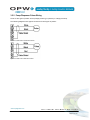
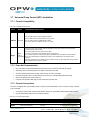
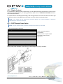
For Reference, fuel control field wiring diagrams for the following equipment, including Bennett, Fill-Rite, and
Wayne products, can be found on the OPWGlobal.com website (technician login required).
http://www.opwglobal.com/TechSupport/TechniciansPortal/fuel-control-field-wiring-diagrams-fordispensing.aspx
•
Bennett 3800 Duo-1
•
Bennett 3800 Duo-2
•
Bennett 3800 Single
•
Bennett Mech
•
Fill-Rite
•
Gasboy 9100 Disp
•
Gasboy 9100 Duo-1 Pump
•
Gasboy 9100 Duo-2 Pump
•
Gasboy 9800 Disp
•
Gasboy Pump
•
Gasboy 9850KX
•
Wayne Reliance Dual Disp
•
Wayne Reliance Duo-2
•
Wayne Reliance Single Disp
•
Wayne Reliance Single Pump
•
Wayne Select Dual
•
Wayne Select Duo-2
•
Wayne Select Single Duo-1 Pump
•
Wayne Select Single
www.opwglobal.com
Doc. #: M1700, Rev. 07
Page 2 of 107
Table of Contents
1 Cautions! Read First.............................................................................................................................. 6 1.1 FCC Compliance ........................................................................................................................... 6 1.2 Warnings!....................................................................................................................................... 6 1.2.1 2 Introduction............................................................................................................................................ 8 2.1 Terminology ................................................................................................................................... 8 2.1.1 2.2 3 Installation Codes & Hazardous Areas .................................................................................. 6 FSC3000 General Terminology ............................................................................................. 8 Technical Specifications ................................................................................................................ 9 2.2.1 Fuel Site Controller ................................................................................................................ 9 2.2.2 Fuel Island Terminals ........................................................................................................... 10 2.2.3 Pump Control ....................................................................................................................... 11 Site Installation .................................................................................................................................... 13 3.1 Warnings...................................................................................................................................... 13 3.1.1 Enclosure Mounting ............................................................................................................. 13 3.2 Preparation of System Conduit and Wiring Requirements .......................................................... 14 3.3 System Installation Overview....................................................................................................... 16 3.3.1 Typical Installation Diagram of an Integrated FSC3000 with Mechanical Pump Control ..... 16 3.3.2 Typical Installation Diagram of an Integrated FSC3000 with Electronic Pump Control ....... 17 3.3.3 Typical Installation Diagram of a Remote FSC3000 with Mechanical Pump Control .......... 18 3.3.4 Typical Installation Diagram of a Remote FSC3000 with Electronic Pump Control ............. 19 3.4 FIT Installation ............................................................................................................................. 20 3.4.1 FIT Power, Petro-Net and HM-485 ...................................................................................... 20 3.4.2 FIT Conduit Installation ........................................................................................................ 21 3.5 PCT Installation (for K800 Hybrid Installations) ........................................................................... 23 3.5.1 Pump/Dispenser Control Wiring ........................................................................................... 23 3.5.2 Pump/Dispenser Pulser Wiring ............................................................................................ 24 3.6 PCM Installation........................................................................................................................... 25 3.6.1 Installing PCM(s) in a C/OPT or FIT500 Pedestal ............................................................... 25 3.6.2 Remote PCM/EPC Power, Petro-Net and HM-485 .............................................................. 26 3.6.3 PCM/PCT Pump Control & Pulser (Mechanical Control) Conduit Requirements ................ 27 3.6.4 Installing PCM(s) in a Remote Enclosure ............................................................................ 29 3.6.5 Remote PCM Power Wiring ................................................................................................. 29 3.7 Universal Pump Control (UPC) Installation.................................................................................. 31 3.7.1 Console Compatibility .......................................................................................................... 31 www.opwglobal.com
Doc. #: M1700, Rev. 07
Page 3 of 107
3.7.2 Petro-Net Communication .................................................................................................... 31 3.7.3 Console Connections ........................................................................................................... 31 3.7.4 EPROM Installation .............................................................................................................. 32 3.8 3.8.1 Pump Types ......................................................................................................................... 33 3.8.2 DPC Pump Control (Electronic Control) Conduit Requirements .......................................... 34 3.8.3 Installing DPC Interface in a Remote Enclosure (for Wayne and Gilbarco) ......................... 35 3.8.4 Installing DPC Interface in a Terminal Pedestal (for Wayne and Gilbarco) ......................... 37 3.8.5 DPC Interface Jumper Setup (for Wayne and Gilbarco) ...................................................... 39 3.8.6 Installing a Remote DPC Interface (for Gasboy ) ................................................................ 41 3.8.7 Installing DPC Interface in a Terminal Pedestal (for Gasboy®) ........................................... 42 3.9 ®
Dispenser Terminal Control (DTC) Installation ............................................................................ 43 3.9.1 Terminal Types .................................................................................................................... 43 3.9.2 DPC with Dispenser Terminal Control (DTC)....................................................................... 44 3.9.3 Installing DTC in a Remote Enclosure ................................................................................. 45 3.10 4 Direct Pump Control (DPC) Installation ....................................................................................... 33 FSC3000 Installation ................................................................................................................. 49 3.10.1 Integrated FSC3000 Communication Conduit ................................................................... 49 3.10.2 Remote FSC3000 .............................................................................................................. 51 3.10.3 SIMM Activation ................................................................................................................. 51 3.10.4 Wireless Radio Modem Installation ................................................................................... 51 3.10.5 FSC3000 Access Connections — Methods ........................................................................ 52 3.10.6 FSC3000 Access Connections — Baud Rate Setting ....................................................... 53 3.10.7 FSC3000 Additional Connections ...................................................................................... 54 System Startup & Testing.................................................................................................................... 57 4.1 Startup and Testing ..................................................................................................................... 57 4.2 K800 Hybrid Startup/Configuration .............................................................................................. 58 4.2.1 Configuration (DIP Switches & Jumper) .............................................................................. 58 4.2.2 Power-Up Test ..................................................................................................................... 60 4.2.3 Display Contrast ................................................................................................................... 60 4.2.4 FIT Test Mode ...................................................................................................................... 60 4.2.5 PCT Testing ......................................................................................................................... 60 4.3 C/OPT Startup/Configuration ....................................................................................................... 61 4.3.1 Power-up Test ...................................................................................................................... 61 4.3.2 Display Contrast ................................................................................................................... 62 4.3.3 C/OPT Receipt Printer Option .............................................................................................. 62 www.opwglobal.com
Doc. #: M1700, Rev. 07
Page 4 of 107
4.3.4 4.4 FIT500 Startup/Configuration ...................................................................................................... 76 4.4.1 Power-up Test ...................................................................................................................... 76 4.4.2 Receipt Printer Paper ........................................................................................................... 77 4.4.3 FIT500 Configuration (Setup Mode) .................................................................................... 78 4.4.4 Test Mode ............................................................................................................................ 81 4.5 PCM Startup/Configuration .......................................................................................................... 85 4.5.1 Configuration (DIP Switches) ............................................................................................... 85 4.5.2 PCM Testing ........................................................................................................................ 88 4.6 UPC Startup/Configuration .......................................................................................................... 89 4.6.1 5 Configuration (Setup/Test Mode) ......................................................................................... 65 Configuration (DIP, Toggle Switches, Consoles) ................................................................. 89 4.7 DPC Startup/Configuration .......................................................................................................... 93 4.8 FSC3000 Configuration/Testing .................................................................................................. 94 4.8.1 Cold Start ............................................................................................................................. 94 4.8.2 Forced Cold Start ................................................................................................................. 94 4.8.3 Configuration ........................................................................................................................ 94 4.8.4 FSC3000 Ethernet Port Setup ............................................................................................. 94 4.8.5 Bluetooth , WiFi, Cell Modem Setup ................................................................................... 96 4.8.6 USB Memory Key Operation ................................................................................................ 97 4.8.7 Journal Printer Setup ........................................................................................................... 99 4.8.8 System Testing .................................................................................................................. 100 ®
System Maintenance ......................................................................................................................... 105 5.1 FSC3000 (Remote Only) Maintnenance ................................................................................... 105 5.2 Fuel Island Terminal Maintenance............................................................................................. 105 5.3 Remote PCM/EPC ..................................................................................................................... 106 5.4 Journal Printer ........................................................................................................................... 106 www.opwglobal.com
Doc. #: M1700, Rev. 07
Page 5 of 107
1 Cautions! Read First.
1.1 FCC Compliance
This device [the FSC3000™] complies with Part 15 of the FCC Rules. Operation is subject to the following two
conditions: (1) this device may not cause harmful interference, and (2) this device must accept any interference
received, including interference that may cause undesired operation.
1.2 Warnings!
This manual contains many important warnings. Do not ignore these warnings! Failure to comply with the
warnings may create conditions dangerous to personnel and/or equipment.
Do not mount your system site controller, or any other electrical part of the system, including printers and
modems, within or above the defined "hazardous" areas.
1.2.1 Installation Codes & Hazardous Areas
Any fuel dispenser is a hazardous area as defined in the National Electrical Code. Installation must be in
accordance with the following:
•
National Electrical Code (NFPA No.70)
•
Automotive and Marine Service Station Code (NFPA No. 30A)
The installer is responsible to investigate and follow any local codes.
OPW Fuel Management System’s fuel control systems are listed for use in a non-classified area. All of the
equipment must be installed outside of the hazardous areas.
NOTE: Local codes may dictate specific installation requirements. Installation is subject to approval by the
local authority having jurisdiction at the site.
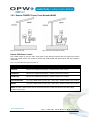
Exception
OPW Terminals are designed to be installed above the hazardous area when using the terminal’s associated
pedestal.
Figure 1-1 Gasoline Dispensers
Figure 1-2 Gasoline Dispensers (high hose)
www.opwglobal.com
Doc. #: M1700, Rev. 07
Page 6 of 107
Figure 1-3 Compressed Natural Gas (CNG) Dispensers
NOTE: The pedestal may be mounted in the hazardous area. When the pedestal is equipped with a
knockout plate, such as with the C/OPT™ and FIT500™, this plate must be above the hazardous area. All
pedestal conduit seal-offs must be above the hazardous area. Any unused knockout holes that have been
removed must be sealed.
www.opwglobal.com
Doc. #: M1700, Rev. 07
Page 7 of 107
2 Introduction
This manual discusses the installation and configuration of three Fuel Control Systems: the K800™ Hybrid, the
C/OPT and the FIT500, as well as optional features that may have been purchased with your system. All of
these systems use the FSC3000 to control the system operation. The FSC3000 may be housed in its own
enclosure or may be located inside any of the Fuel Island Terminals.
2.1 Terminology
Identifies terms assigned to specific components and functions within the Fuel Control System.
2.1.1 FSC3000 General Terminology
Fuel Site Controller (FSC): Hardware/firmware used to control the fueling system.
Fuel Island Terminal (FIT): Generic term we use to describe one of the three types of terminals the FSC3000based fuel-management system can interface to. Every FSC3000 requires at least one terminal except when
the system is equipped with DTC (see below for DTC definition).
There are currently three (3) types of fuel island terminals:
•
K800 Hybrid
•
C/OPT (Commercial Outdoor Payment Terminal)
•
FIT500
Pump Control Terminal (PCT): Hardware used to control mechanical pumps via pump relay board.
Pump Control Module (PCM): Hardware used to control mechanical pumps.
Universal Pump Controller (UPC): Hardware that allows the FSC3000-based fuel-management system to
control electronic pumps by using a pump manufacturer’s console or pump controller.
Direct Pump Control (DPC): Hardware that allows the FSC3000-based fuel-management system to control
electronic pumps directly using the pump manufacturer’s pump protocol.
Dispenser Terminal Controller (DTC): Hardware that emulates the FIT for each fueling position connected to
the system by utilizing the dispenser's built-in card terminal in lieu of a FIT, but can only be used in remote
applications.
Petro-Net™: RS-485 (2-wire twisted pair) communication wires used to connect main components together.
www.opwglobal.com
Doc. #: M1700, Rev. 07
Page 8 of 107
2.2 Technical Specifications
Details the technical specifications (i.e., dimensions, operating temperature range, power and wiring
requirements) of the fuel site controller, fuel site terminal, mechanical pump control and electronic pump
control.
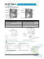
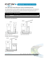
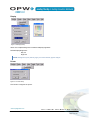
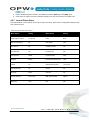
2.2.1 Fuel Site Controller
The FSC3000 Fuel Site Controller may be housed in its own enclosure or located inside a FIT. See below for
images of an integrated FSC verses a remote FSC.
Table 2-1 Integrated Fuel Site Controller in Terminal
K800 Hybrid FIT
FIT500 FIT
C/OPT FIT
Table 2-2 Remote/Stand Alone Fuel Site Controller
FSC3000 Fuel Site Controller
Table 2-3 FSC3000 Technical Specifications
Remote FSC3000
Integrated FSC3000
Cabinet Dimensions (H x W x D)
2-7/8" x 10" x 8-1/8"
(7.3 cm x 25.4 cm x 20.6 cm)
See specific FIT specifications
Power Requirements
85-265 VAC, 50/60 Hz; 1A @ 115 VAC;
0.7 A @ 230 VAC
See specific FIT specifications
Operating Temp. Range
32°F - 122°F (0°C – 50°C)
See specific FIT specifications
8 RJ-45 (RS-232) Max. Length
50' (15.2 m)
50' (15.2 m)
1 DIN (RS-485) (Petro-Net)
Max. Length
5,000' (1,524 m)
5,000' (1,524 m)
www.opwglobal.com
Doc. #: M1700, Rev. 07
Page 9 of 107
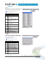
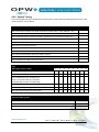
2.2.2 Fuel Island Terminals
The FSC3000-based fuel-management system has three (3) types of Fuel Island Terminals available.
Table 2-4 Fuel Island Terminals
K800 Hybrid FIT
C/OPT FIT
FIT500 FIT
Table 2-5 FIT Technical Specifications
K800 Hybrid
C/OPT
FIT500
Cabinet Dimensions
12" H x 13" W x 12" D
(30.5 cm x 33 cm x 30.5 cm)
19" H x 16" W x 12" D
(48.3 cm x 40.6 cm x 30.5 cm)
19" H x 16" W x 12" D
(48.3 cm x 40.6 cm x 30.5 cm)
Pedestal Dimensions
50" H x 12-1/2" W x 6-5/8" D
(127 cm x 31.8 cm x 16.8 cm)
48" H x 14" W x 8" D
(121.9 cm x 35.6 cm x 20.3 cm)
42" H x 17-1/2" W x 9" D
(106.7 cm x 44.5 cm x 22.9 cm)
Power Requirements
115/230 VAC; 50/60 Hz
200W maximum
115/230 VAC; 50/60 Hz
200W maximum
115/230 VAC; 50/60 Hz
250W maximum
Operating Temp.
Range
-40°F - 122°F (-40°C - 50°C)
-40°F - 122°F (-40°C - 50°C)
-40°F - 122°F (-40°C - 50°C)
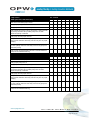
Mag. Card Reader
STD
STD
STD
ChipKey Reader
®
OPT
OPT
---
Prox. Card/Key
Reader
OPT
OPT
---
Dual Readers
---
OPT
---
Text Display
STD
OPT - Deduct
---
Graphics Display
---
STD (5” Monochrome)
STD (10” Color)
User-Defined Images
---
---
STD
Receipt Printer
---
OPT
OPT
Alphanumeric Entry
Single key
OPT
OPT
Wireless
Communication
OPT
OPT
OPT
Enclosure & Pedestal
Painted steel
Painted steel
Stainless steel
Internal FSC
OPT
OPT
OPT
Internal Pump Control
OPT (Up to 4 hoses/FIT)
OPT (Up to 8 hoses/FIT)
OPT (Up to 8 hoses/FIT)
NOTE: The purchase of optional items may result in additional cost.
www.opwglobal.com
Doc. #: M1700, Rev. 07
Page 10 of 107
2.2.3 Pump Control
The FSC3000-based fuel-management system provides various methods for controlling fuel dispensers.
Mechanical Pump Control
The FSC3000-based fuel-management system has two types of mechanical pump control:
•
K800 Hybrid PCT (Pump Control Terminal) allows control of mechanical pumps by using up to two
(2) hose kits; thereby, allowing four (4) fueling points for each FIT board. This option is only available if
K800 Hybrid terminals are used.
•
PCM (Pump Control Module) is a stand-alone board that can be mounted into a C/OPT or FIT500
pedestal, or otherwise, mounted into a remote PCM box. The remote PCM enclosure can contain one
master and one slave PCM to control up to four (4) mechanical dispensers, and is weatherproof and
suitable for outdoor mounting.
NOTE: C/OPT and FIT500 terminals can support two master/slave PCMs for a total of eight (8) fueling
points.
Table 2-6 Mechanical Pump Control
K800 Hybrid PCT
Pedestal-mounted PCM
MASTER
SLAVE
Remote PCM
MASTER
SLAVE
Table 2-7 Mechanical Pump Control Technical Specifications
K800 Hybrid PCT
Pedestal-mounted PCM
Remote PCM
Cabinet Dimensions
(H x W x D)
See K800 Hybrid
FIT specifications
See C/OPT or FIT500
FIT specifications
10" x 12-1/2" x 5-11/16"
(25.4 cm x 31.8 cm x 14.4 cm)
Power Requirements
See K800 Hybrid FIT
specifications
See C/OPT or FIT500 FIT
specifications
115/230 VAC; 50/60 Hz;
1.0/.06 A
Operating
Temperature Range
See K800 Hybrid FIT
specifications
See C/OPT or FIT500 ™ FIT
specifications
-40°F - 122°F (-40°C - 50°C)
Relay Contact
Rating
240 VAC; 20 A; 3/4 HP
240 VAC; 20 A; 3/4 HP
240 VAC; 20 A; 3/4 HP
“In-Use” Detection
Current Sense (100 mA)
Voltage Sense 120-240 V or
Handle Sense
Voltage Sense 120-240 V or
Handle Sense
Pulser Type
Single Channel
Single Channel
Single Channel
Pulser Output
Mechanical (contact)
Electronic (5-12 VDC)
Mechanical (contact)
Electronic (5-12 VDC)
Mechanical (contact)
Electronic (5-12 VDC)
Pulser Divide Rate
1:1 – 1000:1
1 pulse increments
1:1 – 1000:1
1 pulse increments
1:1 – 1000:1
1 pulse increments
Max. Pulse Speed
(50% duty cycle)
6,000 Mechanical
100,000 Electronic
6,000 Mechanical
100,000 Electronic
6,000 Mechanical
100,000 Electronic
www.opwglobal.com
Doc. #: M1700, Rev. 07
Page 11 of 107
Electronic Pump Control
The FSC3000-based fuel-management system has two types of electronic pump control:
•
DPC (Direct Pump Control) allows the FSC3000 to directly control electronic pumps using the
manufacturer’s dispenser protocol.
•
UPC (Universal Pump Control) allows the FSC3000 to control pumps by the manufacturer’s
console/pump controller box (PIB, PAM or DHC).
Table 2-8 Electronic Pump Control
UPC
Pedestal-mounted DPC
Remote DPC
Table 2-9 Electronic Pump Control Technical Specifications
UPC
Pedestal-mounted DPC
Remote DPC
Cabinet Dimensions
(H x W x D)
N/A
See C/OPT or FIT500
FIT specifications
10" x 12-1/2" x 5-11/16"
(25.4 cm x 31.8 cm x 14.4 cm)
Power Requirements
115 VAC; 50/60 Hz
See C/OPT or FIT500
FIT specifications
115/230 VAC; 50/60 Hz;
1.0/.06 A
Operating
Temperature Range
32°F - 122°F (0°C - 50°C)
See C/OPT or FIT500
FIT specifications
-40°F - 122°F (-40°C - 50°C)
Gilbarco Pumps
Yes
Yes
Yes
Wayne Pumps
Yes
Yes
Yes
www.opwglobal.com
Doc. #: M1700, Rev. 07
Page 12 of 107
3 Site Installation
The instructions in this section of the manual describe typical site installations. Due to the flexibility of the
system and the unique nature of every site, it is not possible to show every possible installation scenario.
However, for every installation local codes and regulations must be observed.
NOTE: Local codes may dictate specific installation requirements. Installation is subject to approval by the
local authority having jurisdiction at the site.
The system installation instructions are the same for all FSC3000-based K800 Hybrid, C/OPT and FIT500
systems. Specific differences between the systems are noted within the text.
The term FIT is used generically to describe any of the Fuel Island Terminals from these systems.
NOTE: Installation of an Integrated FSC3000 (an FSC3000 mounted in the FIT) has separate typical
installation diagrams than of a Remote FSC3000. Follow the diagram that applies to your system.
3.1 Warnings
This manual contains many important warnings. Do not ignore these warnings! Failure to comply with the
warnings may create conditions dangerous to personnel and/or equipment.
Do not mount your system site controller, or any other electrical part of the system, including printers and
modems, within or above the defined "hazardous" areas.
CAUTION: The pedestal may be mounted in the hazardous area. When the pedestal is equipped with a
knockout plate, such as in the C/OPT and FIT500, this plate must be above the hazardous area. All pedestal
conduit seal-offs must be above the hazardous area. Any unused knockout holes that have been removed
must be sealed.
3.1.1 Enclosure Mounting
Knockouts and mounting means are provided for all cabinetry. Do not drill holes in any of the enclosures. Doing
so would violate the safety listing of the system.
www.opwglobal.com
Doc. #: M1700, Rev. 07
Page 13 of 107
3.2 Preparation of System Conduit and Wiring Requirements
All wiring and conduit runs must also conform to the National Electrical Code (NFPA No. 70), Automotive and
Marine Service Station Code (NFPA No. 30A), and all national, state and local codes.
All wiring from the building out to the Fuel Islands must be installed in threaded, rigid, metal conduit and have
required seal-offs. AC and DC power wires may share conduit, providing they meet the Petro-Net™ wiring
specified; otherwise AC and DC power wires must be installed in separate conduits.
Conduit Sealing
Figure 3-1 Conduit Sealing
Conduit entering the hazardous area must have a seal-off installed 18” (0.46 m) above grade to prevent liquid
or fumes from entering the area.
WARNING: Shielded cable is not vapor-tight!
When running shielded cable through a seal-off, strip the cable jacket back so about 3” (7.6 cm) of jacketed
cable protrudes past each seal-off.
CAUTION: Do not damage the shield wire! Stripped section must be in the sealed-off area.
Petro-Net Wiring
The FITs, PCMs, FSC3000 and other devices communicate using an RS-485 protocol called Petro-Net. PetroNet wiring is a twisted-pair of 18 AWG wires that must be twisted together to provide immunity to electrical
noise. You can order Petro-Net from OPW as Part #: 12-1029.
Petro-Net wiring can run a maximum of 5,000' (1,524 m).
WARNING: Even though Petro-Net, HM Petro-Net, WCU Ethernet and WCU power are low-voltage wiring,
they are not intrinsically safe wiring; therefore, they should never be installed with any intrinsically safe wiring.
Grounding
The OPW fuel control system incorporates internal noise-suppression circuitry. To ensure proper operation of
the equipment and provide necessary safety, all devices of the OPW system must be grounded.
A ground wire (per local code) must be connected between the device’s ground terminal and the main electrical
service panel. One earth ground connection is required per OPW device. The FSC3000 should be connected
to the grounded outlet from the same main electrical service panel. Do not rely on the conduit to provide ground
connections.
www.opwglobal.com
Doc. #: M1700, Rev. 07
Page 14 of 107
Circuit Breakers
Power to the FITs and all system hardware (FSC3000, Journal Printer, etc.) must be supplied from dedicated
circuit breakers. No other equipment should be powered from these breakers, including the pumps that are
being controlled. The AC power for the FITs may be grouped together for multiple units. It is recommended that
no more than eight (8) FITs be supplied from one breaker.
Pulser Wire
For mechanical pump installations, pulser wires must meet the pulser manufacturer’s wire requirements when
installed in separate conduit from the pump-control wires. If installed in the same conduit as the pump-control
wires, then the wire must be UL-style 2567 or equivalent. You can order Shielded Pulser Cable from OPW as
Part #: 12-1025 (two-conductor) or Part #: 12-1026 (four-conductor).
FIT Conduits
All FIT Conduits from the seal-off must be stubbed to the bottom of the K800 Hybrid FIT enclosure or the
pedestal conduit plate of the C/OPT and FIT500 pedestal.
www.opwglobal.com
Doc. #: M1700, Rev. 07
Page 15 of 107
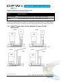
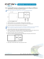
3.3 System Installation Overview
The four typical installation diagrams below show the different wiring and conduit for an integrated FSC3000
with mechanical or electrical pump control and for a remote FSC3000 with mechanical or electrical pump
control. Review the installation diagram that matches one's purchased system.
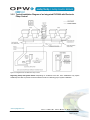
3.3.1 Typical Installation Diagram of an Integrated FSC3000 with Mechanical
Pump Control
Figure 3-2 Integrated FSC with Mechanical Pump Control
Regarding Pump and System Power: Depending on conditions at the site, some installations may require
shielded power cable to prevent excessive electrical noise from affecting proper system installation.
www.opwglobal.com
Doc. #: M1700, Rev. 07
Page 16 of 107
3.3.2 Typical Installation Diagram of an Integrated FSC3000 with Electronic
Pump Control
Figure 3-3 Integrated FSC with Electronic Pump Control
Regarding Pump and System Power: Depending on conditions at the site, some installations may require
shielded power cable to prevent excessive electrical noise from affecting proper system installation.
www.opwglobal.com
Doc. #: M1700, Rev. 07
Page 17 of 107
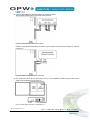
3.3.3 Typical Installation Diagram of a Remote FSC3000 with Mechanical Pump
Control
Figure 3-4 Remote FSC with Mechanical Pump Control
www.opwglobal.com
Doc. #: M1700, Rev. 07
Page 18 of 107
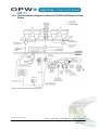
3.3.4 Typical Installation Diagram of a Remote FSC3000 with Electronic Pump
Control
Figure 3-5 Remote FSC with Electronic Pump Control
www.opwglobal.com
Doc. #: M1700, Rev. 07
Page 19 of 107
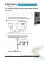
3.4 FIT Installation
CAUTION: Install your FIT a minimum of 18" (45.7 cm) from the nearest conventional pump or dispenser or
a minimum of 18" (45.7 cm) from the nearest overhead pump or dispenser.
3.4.1 FIT Power, Petro-Net and HM-485
Figure 3-6 Terminal
Figure 3-7 Terminal (shared conduit)
Terminal Power Conduit
This conduit should run from the main circuit panel to each FIT and may be looped from terminal to terminal.
This conduit should only contain the Terminal Feed, Terminal Neutral and Ground wires, with the exceptions
noted below.
Table 3-1 FIT Power Wiring Requirements
Wires
Wire Requirements
Terminal Feed
Minimum #14 AWG Stranded (Black) – Oil/Gas resistant, Wet Locations
Terminal Neutral
Minimum #14 AWG Stranded (White) – Oil/Gas resistant, Wet Locations
Terminal Ground
Minimum #14 AWG Stranded (Green) – Oil/Gas resistant, Wet Locations
Petro-Net (RS-485)*
Two (2) #18 AWG twisted (10 per ft) pair – 600 V-rated – Oil/Gas resistant, Wet Locations
HM-485*
Two (2) #18 AWG twisted (10 per ft) pair – 600 V-rated – Oil/Gas resistant, Wet Locations
*NOTE: Petro-Net communications wire may share terminal power conduit when the Petro-Net cable voltage
insulation rating is 600 V.
www.opwglobal.com
Doc. #: M1700, Rev. 07
Page 20 of 107
Terminal Petro-Net Communication Conduit
Table 3-2 FIT Communication Wiring Requirements
Wires
Wire Requirements
Petro-Net (RS-485)
Two (2) #18 AWG twisted (10 per ft) pair – Oil/Gas resistant, Wet Locations
HM-485
Two (2) #18 AWG twisted (10 per ft) pair – Oil/Gas resistant, Wet Locations
This conduit is required when you use RS-485 Communication wire that doesn’t meet requirements to be
installed in the Terminal Power Conduit, or you choose to have separate conduit. This conduit should run from
where the Petro-Net junction box is mounted to each terminal. This conduit may be looped from terminal to
terminal.
3.4.2 FIT Conduit Installation
All conduits in the FIT pedestal should terminate at a point 18" (45.7 cm) above the ground into a seal-off.
Install the following 1/2” (1.27 cm) or 3/4” (1.91) rigid steel conduits, as applicable, to the area where the FIT
pedestal will be located:
•
To the FIT power source
•
To other FITs or External FSC for Petro-Net communications
•
To the remote communication access panel for phone line(s), Ethernet
•
To the antenna for wireless modem, cellular modem, etc.
•
To each mechanical pump or dispenser for control and pulser wires (for Internal PCM only)
Please refer to the appropriate pedestal diagram installations below.
Figure 3-8 K800 Hybrid Pedestal
Figure 3-9 C/OPT Pedestal
Figure 3-10 FIT500 Pedestal
www.opwglobal.com
Doc. #: M1700, Rev. 07
Page 21 of 107
FIT Pedestal and Enclosure Mounting
1.
Remove the access panel from the pedestal. The K800 Hybrid and C/OPT panels are held on with
screws. The FIT500 panel slides up and out.
2.
Install four (4) 3/8” threaded studs in the ground.
3.
Install Pedestal base plates (K800 and C/OPT only) atop the four (4) studs.
4.
Set the FIT pedestal atop the four (4) studs.
5.
Secure the pedestal to the studs with the four (4) nuts and lock washers.
6.
Set the FIT enclosure atop the pedestal.
7.
Secure the FIT enclosure tightly to the pedestal with the supplied bolts and washers.
FIT Flex Conduit Installation
1.
Remove knockouts from the base of the FIT enclosure.
2.
Install Flex Conduit from the rigid conduit to the knockouts in the FIT enclosure (K800 Hybrid) or
pedestal conduit plate (C/OPT and FIT500 pedestals).
NOTE: Any unused knockout holes must be sealed to meet NEC compliance codes.
FIT Power and Communication Wiring
1.
Pull three (3) #14 AWG wires (green, black and white) from a dedicated circuit breaker to supply power
to the FIT(s).
NOTE: Petro-Net communication to other FIT(s) should also be pulled in this conduit.
2.
Connect power and neutral wires to the power connection terminal block marked “LINE” (or “L”) and
“NEUTRAL” (or “N”). Connect the ground to the wire to the terminal labeled “GROUND” (or “GND”).
CAUTION: Petro-Net communication wires can share the conduit with the power wiring provided the wires
have the same voltage-insulation rating as the power wires.
3.
Connect the Petro-Net wires to the communication terminal block. Polarity must be observed. Attach
all (1) terminals together and all (2) terminals together.
NOTE: Petro-Net is connected internally on integrated units. There is no need to connect to the Petro-Net
terminal block unless there are additional FITs or other devices to connect.
Power & Petro-Net
Table 3-3 Power and Petro-Net Wiring
K800 Hybrid
C/OPT
FIT500
www.opwglobal.com
Doc. #: M1700, Rev. 07
Page 22 of 107
3.5 PCT Installation (for K800 Hybrid Installations)
CAUTiON: The K800 Hybrid PCT is supplied with noise suppressors that must be installed across each
solenoid valve and/or motor contactor. Failure to do so can cause erratic system operation caused by the
electrical noise generated by the coils in these devices.
3.5.1 Pump/Dispenser Control Wiring
Wire the pump-control wires to the corresponding pump position on the PV240 Pump Relay Board.
Use one of the two typical PCT Pump Wiring diagrams below based on the type of suction pump or dispenser.
Pump Position #1
1&2
Current Sense (100 mA) (motor/solenoid control)
3&4
Auxiliary (reset control)
D
Pulser Cable Shield Ground
C
Pulser Power 12V
B
Pulser Signal
A
Pulser Common
Figure 3-11 PCT Pump Wiring
Figure 3-12 Self-contained Pump, Power Reset
Figure 3-13 Dispenser, Power Reset
www.opwglobal.com
Doc. #: M1700, Rev. 07
Page 23 of 107
3.5.2 Pump/Dispenser Pulser Wiring
There are two types of pulsers: active (voltage-producing) or passive (no voltage produced).
The following diagrams show typical connections for both types of pulsers:
Figure 3-14 Wire Passive Veeder-Root Pulser
Figure 3-15 Wire Active Veeder-Root Pulser
www.opwglobal.com
Doc. #: M1700, Rev. 07
Page 24 of 107
3.6 PCM Installation
The PCMs may be installed in the C/OPT, FIT500 or in the remote PCM cabinet.
Figure 3-16 PCM Locations
Choose the appropriate section in the pages that follow.
3.6.1 Installing PCM(s) in a C/OPT or FIT500 Pedestal
C/OPT Pedestal Mounting
•
Mount the PCM Master Board in the pedestal’s lower-left position. The
pedestals have four (4) positions total.
•
Mount the PCM Slave Board in the lower-right position. Another
master/slave set can be mounted above the first.
•
Plug the 20-1618 Cable to the connector on the power supply chassis in
the top of the enclosure.
•
When wiring two (2) Master Boards, daisy-chain the wiring as shown
below:
Figure 3-17 PCM Connection Wiring
Figure 3-18 C/OPT PCM
Pedestal Mounting
www.opwglobal.com
Doc. #: M1700, Rev. 07
Page 25 of 107
3.6.2 Remote PCM/EPC Power, Petro-Net and HM-485
Figure 3-19 Remote PCM
Figure 3-20 Remote PCM (shared conduit)
Remote PCM Power Conduit
This conduit should run from the main circuit panel to each Remote PCM and may be looped from PCM to
PCM. This conduit should only contain the PCM Feed, PCM Neutral and Ground wires, with the exceptions
noted below.
Table 3-4 Remote PCM Power Wiring Requirements
Wires
Wire Requirements
PCM Feed
Minimum #14 AWG Stranded (Black) – Oil/Gas resistant, Wet Locations
PCM Neutral
Minimum #14 AWG Stranded (White) – Oil/Gas resistant, Wet Locations
PCM Ground
Minimum #14 AWG Stranded (Green) – Oil/Gas resistant, Wet Locations
Petro-Net (RS-485)*
Two (2) #18 AWG twisted (10 per ft) pair – 600 V-rated – Oil/Gas resistant, Wet Locations
HM-485*
Two (2) #18 AWG twisted (10 per ft) pair – 600 V-rated – Oil/Gas resistant, Wet Locations
*NOTE: Petro-Net communications wire may share terminal power conduit when the Petro-Net cable voltage
insulation rating is 600 V.
www.opwglobal.com
Doc. #: M1700, Rev. 07
Page 26 of 107
Remote PCM Petro-Net Communication Conduit
Table 3-5 Remote PCM Communication Wiring Requirements
Wires
Wire Requirements
Petro-Net (RS-485)
Two (2) #18 AWG twisted (10 per ft) pair – Oil/Gas resistant, Wet Locations
HM-485
Two (2) #18 AWG twisted (10 per ft) pair – Oil/Gas resistant, Wet Locations
This conduit is required when you use RS-485 Communication wire that doesn’t meet requirements to be
installed in the Remote PCM Power Conduit or you choose to have separate conduit. This conduit should run
from the Petro-Net junction box to each PCM. This conduit may be looped from Remote PCM to Remote PCM.
3.6.3 PCM/PCT Pump Control & Pulser (Mechanical Control) Conduit
Requirements
Figure 3-21 FIT (K800 Hybrid) PCT/PCM
Figure 3-22 FIT (K800 Hybrid) PCT/PCM (shared conduit)
Figure 3-23 Remote PCM
Figure 3-24 Remote PCM (shared conduit)
www.opwglobal.com
Doc. #: M1700, Rev. 07
Page 27 of 107
Pump Control Conduit
This conduit should run from the FIT pedestal and Remote PCM to the pump junction box. This conduit should
only contain the Pump Control wires with the exceptions noted below. Wires required are per fueling point; if
the conduit is running to two double-sided fuel pumps then four times the wire is required as shown below.
K800 Hybrid PCT
Table 3-6 K800 Hybrid PCT Wiring Requirements
Wires (per fueling point)
Pump Control
Pulser Wire*
Wire Requirements
Four (4) wires - must meet pump manufacturer’s specification for pump being
controlled
Two- or four-wire cable shielded– 600 V-rated – Oil/Gas resistant, Wet Locations ULstyle 2567
PCM
Table 3-7 PCM Wiring Requirements
Wires (per fueling point)
Wire Requirements
Pump Control
Six (6) wires - must meet pump manufacturer’s specification for pump being controlled
Pulser Wire*
Two- or four-wire cable shielded– 600 V-rated – Oil/Gas resistant, Wet Locations ULstyle 2567
NOTE*: Pump Pulser Wires may share Pump Control Conduit when they meet the specified requirements.
Pump Pulser Conduit
Table 3-8 Pump Pulser Wiring Requirements
Wires (per fueling point)
Wire Requirements
Pulser Wire
Two- or four-wire cable (shielded recommended, but not required)
This conduit is dedicated to bring the pump pulser wires from the pump junction box to the Terminal Pedestal
and/or Remote PCM box.
Wires required are per fueling point; if conduit is running to two double-sided fuel pumps then four times the
wire is required as shown below.
www.opwglobal.com
Doc. #: M1700, Rev. 07
Page 28 of 107
3.6.4 Installing PCM(s) in a Remote Enclosure
Figure 3-25 PCM Remote Enclosure
Each enclosure can contain one (1) Master Board and one (1) Slave Board to control up to four (4) pumps. Use
additional enclosures to control additional pumps.
•
Attach the enclosure to a wall with fasteners (not supplied).
•
Install the following 1/2” or 3/4” rigid steel conduits, as applicable:
•
To the PCM power source.
•
To the FSC and other PCMs for Petro-Net communication.
•
To each mechanical pump or dispenser for control and pulser wires.
•
Install a power switch for the PCM. (The enclosure has no switch. (See “PCM Wiring” for more details.)
•
Mount the PCM Master Board on the left-side stand-offs in the enclosure. If applicable, mount the
Slave Board on the right-side stand-offs.
•
Connect the output wiring from the power supply to the PCM Master Board at Location J8 PINS 3 and
4. Pins are labeled 15-30 VDC, 12-20 VAC. Polarity is NOT important.
3.6.5 Remote PCM Power Wiring
For remote PCMs, run three (3) 14-AWG wires from the breaker panel and the user-installed ON/OFF switch to
the terminal block inside the enclosure.
Pedestal-mounted PCMs obtain power from the C/OPT or FIT500.
PCM Pump/Dispenser Control Wiring
CAUTION: The PCM is supplied with noise suppressors that must be installed across each solenoid valve
and/or motor contactor. Failure to do so can cause erratic system operation caused by the electrical noise
generated by the coils in these devices.
•
Wire the line-voltage control wires to the corresponding pump position on the PCM Board.
•
Use one of the Typical PCM Pump Wiring Diagrams below based on the type of suction pump or
dispenser.
NOTE: The Pump Control Modules use voltage sense to know when the pump is running.
www.opwglobal.com
Doc. #: M1700, Rev. 07
Page 29 of 107
PCM Board Terminal Identification
Figure 3-26 PCM Master
Figure 3-27 PCM Slave
Table 3-9 PCM Connections
Low-voltage Connections
High-voltage Connections
Gnd – Ground for pulser and flow switch
In-Use – Feedback from solenoid or motor
Pulse – Pulser input
Neutral – Neutral return for In-Use signal
Flow – Flow switch or pump handle input
Relay Contacts – Reset control
+12 V – Supply for pulser
Relay Contacts – Motor control
Figure 3-28 Self-contained Pump, Power Reset
Figure 3-29 Dispenser, Power Reset
NOTE: Two (2) dispensers controlled by a single PCM Master or Slave must be of the same type.
Figure 3-30 Veeder-Root Pulser Wiring
www.opwglobal.com
Doc. #: M1700, Rev. 07
Page 30 of 107
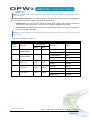
3.7 Universal Pump Control (UPC) Installation
3.7.1 Console Compatibility
Table 3-10 Compatibility Requirements
Brand
Model
Compatibility Requirements
The TS-1000 console must be equipped as follows:
The TS-1000 must have software version 21.2 (or later)
Gilbarco
TS-1000
The TS-1000 must have the MEM #2 Kit installed
The console must have software version 11.0 (or later)
The Wayne 2400+ Site Controller must be equipped with main and companion CPU boards with
software revision 49-23 (or later)
The Plus/2 software must be version 4.20 (or later).
2400,
PIB or
HyperPIB
Wayne
For Plus/3, contact Petro Vend distributor for the correct version.
The controller must have a PIB PLUS kit (Wayne p/n #850314-03) with software version 34000 or
above. The optional Wayne Decade 2400 console may be installed but is not required for UPC
operation.
Data-Link dispensers are compatible with UPC operation except: (1) DL0 dispensers and (2) variableratio blenders with more than four grades.
3.7.2 Petro-Net Communication
•
Run a conduit from the FSC3000 Petro-Net junction box to where the UPC will be located.
•
Attach the UPC’s Petro-Net junction box within three feet of the UPC.
•
The UPC must be within three (3) feet of the Console or Pump Controller.
•
Connect Terminals 1 and 2 on the junction box cover to the corresponding Petro-Net wiring.
•
Secure the junction box cover to the box.
•
Insert the four-pin Petro-Net plug into the socket of the junction box.
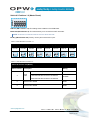
3.7.3 Console Connections
The UPC is shipped with a personality kit that is specific to the manufacturer of the console or pump controller
to be controlled.
•
Connect the 6-pin socket of the RS-232 cable to the 6-inch "personality" cable supplied with the UPC.
•
Plug the personality cable into the console as follows:
Table 3-11 Connection Requirements
Brand
Model
Personality Cable
Port
Gilbarco
TS-1000
20-1436-GIL2
PIB Plus
Wayne
2400, PIB or HyperPIB
20-1436
J-103 Gossip Port on Console
www.opwglobal.com
Doc. #: M1700, Rev. 07
Page 31 of 107
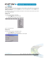
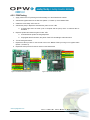
3.7.4 EPROM Installation
The personality kit contains an EPROM (Erasable Programmable Read-Only Memory) chip that contains the
UPC program for the specific console/pump controller.
1.
Remove the cover to the UPC and plug the EPROM into its socket on the UPC circuit board.
Figure 3-31 EPROM Installation
2.
Align the notch on the EPROM with the notch outline on the circuit board and make sure all of the pins
are properly inserted.
3.
Do not replace the cover to the UPC. The switches will be set in the configuration section.
WARNING: Be very careful when handling the EPROM. Avoid applying excessive pressure when inserting
the EPROM into its socket. The EPROM is also sensitive to electrostatic discharge and should be handled in
only a static-free environment.
www.opwglobal.com
Doc. #: M1700, Rev. 07
Page 32 of 107
3.8 Direct Pump Control (DPC) Installation
NOTE: For DPC Interface Jumper Settings for Wayne and Gilbarco pump types, see Section 3.8.5.
3.8.1 Pump Types
The FSC3000 can communicate directly with Wayne, Gilbarco and Gasboy® dispensers.
The DPC interface can connect to the ePC (PetroLink™) to provide handle status – refer to M1701 PetroLink™
Installation and Configuration Manual for more information. Meanwhile, DPC installations without PetroLink™
will only require jumpers to be set up.
Wayne and Gilbarco
The DPC interface utilizes the Electronic Handle Monitor board to provide the DPC interface for Wayne and
Gilbarco. It provides isolation and converts the RS-232 output from the FSC3000 into the current loop
communication required by the dispensers.
Wayne dispensers can connect directly to the interface board or the Wayne distribution box can be used. Either
way, up to eight (8) dispensers can be connected for controlling a maximum of 16 fueling points if the
dispensers are double-sided, eight (8) fueling points if they are all single-sided, or any combination in between.
Gilbarco dispensers can connect directly to the interface board, or the Gilbarco distribution box can be used. If
connecting directly to the interface board, up to eight (8) dispensers can be connected for controlling a
maximum of 16 fueling points if the dispensers are double-sided, or eight (8) fueling points if they are all singlesided or any combination thereof. If the dispensers are double-sided, this can be eight (8) double-sided
dispensers, 16 single-sided dispensers, or any combination thereof.
Gasboy
Gasboy dispensers use an RS-232 to RS-485 converter board to provide isolation and the proper interface.
The dispensers all wire in a 2-wire multi-drop configuration. Up to 16 fueling points may be controlled. This can
be any combination of single- and dual-sided dispensers.
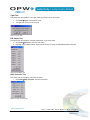
Parts Required
Table 3-12 DPC Parts List
Part #
Part Description
Remote DPC
Pedestal DPC
20-8225
Remote PCM enclosure
Yes
No
20-0612
DPC Interface
Yes
Yes
20-1018
Cable (FSC3000 to DPC Interface)
Yes
Yes
20-1618
Power Cable (C/OPT or FIT500)
No
Yes
www.opwglobal.com
Doc. #: M1700, Rev. 07
Page 33 of 107
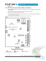
3.8.2 DPC Pump Control (Electronic Control) Conduit Requirements
This conduit should run from the FIT pedestal or Remote DPC to the pump junction box. This conduit should
only contain the Pump Control wires with the exception noted below. Wires required are per dispenser; if
conduit is running to two double-sided fuel pumps then two times the wire is required as shown below.
Table 3-13 Electronic Pump Control Wiring Requirements
Wires (per fueling point)
Wire Requirements
Pump Control*
Two wires – must meet pump manufacturer’s specification for the controlled pump
*NOTE: When using manufacturer’s D-Box, only two wires need to be pulled to the D-Box for all pumps.
For Four (4) or Less Dispensers
Figure 3-32 FIT DPC (direct)
Figure 3-33 Remote DPC (direct)
For More Than Four (4) Dispensers
Figure 3-34 Remote DPC (D-Box)
www.opwglobal.com
Doc. #: M1700, Rev. 07
Page 34 of 107
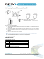
3.8.3 Installing DPC Interface in a Remote Enclosure (for Wayne and Gilbarco)
1.
Attach the enclosure to a wall with fasteners (not supplied).
NOTE: Enclosure needs to be no further than 50' (15.24 m) from FSC3000 controller.
Figure 3-35 DPC Remote Enclosure
4.
Install the following 1/2” or 3/4” rigid steel conduits and wires, as applicable.
5.
DPC power source conduit and pull three (3) 14-AWG wires from the breaker panel.
6.
Pump communication conduit and pull wires from each dispenser.
NOTE: For more than four (4) pump loops use the manufacturer’s distribution box. Pump communication
conduit is not required if manufacturer's distribution box is located near remote DPC enclosure.
7.
Mount the DPC interface board on the right-side stand-offs in the enclosure.
8.
Remove connector from CN12 DPC interface board and attach wiring (grey and orange) from the
power supply cable (P/N: 20-1618) to the connector. (Polarity is NOT important.)
9.
Reconnect connector to CN12 on the DPC interface.
10. Attach Line, Neutral and Ground wires from the breaker panel to the power-connection block.
Figure 3-36 DPC Connections 11. Attach pump communication wires to each pump loop on CN5.
www.opwglobal.com
Doc. #: M1700, Rev. 07
Page 35 of 107
12. Connect Wayne/Gilbarco dispenser directly to the DPC interface.
Wayne Data Distribution Box connected to DPC interface:
Figure 3-37 Wayne D-Box Connection to DPC Board Gilbarco Universal Distribution Box connected to DPC interface. Ensure that the Gilbarco is setup for
current loop.
Figure 3-38 Gilbarco D-Box Connection to DPC Board 13. Run cable (P/N: 20-1018) from Port CN4 to port 4 on the FSC3000 controller. Please note that the
cable can be extended up to 50' (15.2 m).
Figure 3-39 DPC Board Connection to FSC3000 Port 4 www.opwglobal.com
Doc. #: M1700, Rev. 07
Page 36 of 107
3.8.4 Installing DPC Interface in a Terminal Pedestal (for Wayne and Gilbarco)
During an installation where the FSC3000 is integrated into the terminal, the DPC can be mounted in one of the
PCM pedestal mounts.
1.
Mount the DPC interface as shown in the drawing of the pedestal.
2.
Remove connector from CN12 DPC interface board and attach wiring (grey and
orange) from the power supply cable (P/N: 20-1618) to the connector. (Polarity is
NOT important.)
3.
Reconnect connector to CN12 on the DPC interface.
4.
Run cable from pedestal into C/OPT or FIT500 enclosure.
5.
Connect 4-pin connector into C/OPT power supply or FIT500 main board.
NOTE: Petro-Net wires are not used and should be capped.
Figure 3-40 DPC
Installation in
Pedestal
Figure 3-41 DPC Installation in Pedestal
6.
Run cable (P/N: 20-1018) from Port CN4 to port 4 on the FSC3000 controller.
7.
Attach pump communication wires to each pump loop on CN5.
8.
Connect Wayne/Gilbarco dispenser directly to the DPC interface.
Wayne Data Distribution Box connected to DPC interface:
Figure 3-42 Wayne D-Box Connection to DPC Board
www.opwglobal.com
Doc. #: M1700, Rev. 07
Page 37 of 107
Gilbarco Universal Distribution Box connected to DPC interface. Ensure that the Gilbarco is setup for
current loop.
Figure 3-43 Gilbarco D-Box Connection to DPC Board
www.opwglobal.com
Doc. #: M1700, Rev. 07
Page 38 of 107
3.8.5 DPC Interface Jumper Setup (for Wayne and Gilbarco)
•
Set up jumpers to match pump type being connected. See the Wayne/Gilbarco Jumper Settings
illustrations below.
•
When a jumper is set as "ON" this means the jumper will tie both pins together.
•
When "OFF," the jumper should be set on one pin.
•
Some jumpers have three pins; when the jumper says "Pins 1-2" this means the jumper should be set
on Pins 1 and 2 of the 3-pin jumper.
•
On 3-pin jumpers the board is labeled to indicate which pin is number one.
Wayne
Figure 3-44 DPC-Wayne Jumper Settings
www.opwglobal.com
Doc. #: M1700, Rev. 07
Page 39 of 107
Gilbarco
Figure 3-45 DPC-Gilbarco Jumper Settings
www.opwglobal.com
Doc. #: M1700, Rev. 07
Page 40 of 107
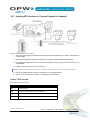
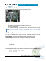
3.8.6 Installing a Remote DPC Interface (for Gasboy®)
Figure 3-46 Remote DPC Interface for Gasboy
1.
Attach the power supply and isolated converter (RS-232 to RS-422/485) to the Velcro® adhered to the
mounting plate.
2.
Mount the mounting plate with power supply and converter attached within 5' (1.52 m) of the FSC3000.
3.
Plug serial cable (P/N: 20-1519-04) into the isolated converter 9-pin port and then into Port 4 of the
FSC3000.
4.
Install pump communication wiring to converter.
NOTE: Polarity is important, so please refer to Gasboy documentation for proper wiring specifications.
5.
Ensure the isolated switch settings are set as shown in the diagram above.
6.
Plug in the power supply.
Gasboy DPC Parts Kit
Table 3-2 Gasboy DPC Components
Part #
Part Description
N/A
Mounting Plate
N/A
Isolated Converter (RS-232 to RS 422/485)
N/A
Power Supply
20-1518-04
Power Cable (C/OPT or FIT500)
www.opwglobal.com
Doc. #: M1700, Rev. 07
Page 41 of 107
3.8.7 Installing DPC Interface in a Terminal Pedestal (for Gasboy®)
Figure 3-47 DPC Interface in a FIT or Gasboy
1.
Attach the power supply and isolated converter (RS-232 to RS-422/485) to the Velcro® adhered to the
mounting plate.
1.
Mount the mounting plate with power supply and converter attached inside terminal pedestal.
2.
Plug serial cable (OPW P/N: 20-1519-04) into the isolated converter 9-pin port and then into Port 4 of
the FSC3000.
3.
Install pump communication wiring to converter.
NOTE: Polarity is important, so please refer to Gasboy documentation for proper wiring specifications.
4.
Ensure the isolated switch settings are set as shown in the diagram above.
5.
Cut the power cord and wire to C/OPT or FIT500 power terminal block.
Gasboy® DPC Parts Kit
Table 3-3 Gasboy DPC Components
Part #
Part Description
N/A
Mounting Plate
N/A
Isolated Converter (RS-232 to RS 422/485)
N/A
Power Supply
20-1518-04
Power Cable (C/OPT or FIT500)
www.opwglobal.com
Doc. #: M1700, Rev. 07
Page 42 of 107
3.9 Dispenser Terminal Control (DTC) Installation
DTC (Dispenser Terminal Control) utilizes the dispenser's built-in card terminal in lieu of a fuel island terminal
and will emulate the fuel island terminal for each fueling position connected to the system. DTC control requires
DPC electronic pump control to function and uses the same conduit wiring.
3.9.1 Terminal Types
DTC can communicate with the Wayne CAT or Gilbarco CRIND. The DTC interface utilizes a second remote
PCM enclosure.
Wayne CAT (Card Authorization Terminal)
The DTC board has RS-485 ports to communicate directly to the Wayne CATs. Up to 12 fueling points can be
controlled. This can be six (6) dual-sided dispensers, 12 single-sided dispensers, or any combination thereof.
Gilbarco CRIND (Card Reader in Dispenser)
In addition to the DTC board, Gilbarco requires a second Electronic Handle Monitor (EHM) board to provide the
isolation and to convert the RS-232 output from the DTC board into the current-loop communication required by
the CRINDs.
CRINDs can connect directly to the Electronic Handle Monitor board or the Gilbarco distribution box. If
connecting directly to the interface board, up to eight (8) dispensers can be connected and a maximum of 12
fueling points can be controlled. For example, the system can control six (6) dual-sided dispensers (12 fueling
points), eight (8) single-sided dispensers (8 fueling points), or a combination thereof, such as four (4) dualsided and four (4) single-sided dispensers (12 fueling points).
If the distribution box is used, then a maximum of 12 fueling points may be connected. This can be six (6)
double-sided dispensers, 12 single-sided dispensers, or any combination thereof.
www.opwglobal.com
Doc. #: M1700, Rev. 07
Page 43 of 107
3.9.2 DPC with Dispenser Terminal Control (DTC)
DTC is an upgrade option to DPC (direct pump control). However, it is only available for remote FSC3000
applications and cannot be pedestal-mounted.
Depending upon the type of dispenser (Wayne or Gilbarco) installation may vary. Wayne DTC is installed in the
same cabinet as the DPC board. Meanwhile, Gilbarco DTC requires additional hardware and is installed in a
separate enclosure.
Wayne DTC
For Four (4) or Less Dispensers
For More than Four (4) Dispensers
Figure 3-48 Remote DPC with DTC (direct)
Figure 3-49 Remote DPC with DTC (D-Box)
Gilbarco DTC
For Four (4) or Less Dispensers
For More than Four (4) Dispensers
Figure 3-50 Remote DPC with DTC (direct)
Figure 3-51 Remote DPC with DTC (D-Box)
www.opwglobal.com
Doc. #: M1700, Rev. 07
Page 44 of 107
3.9.3 Installing DTC in a Remote Enclosure
1.
Attach the enclosure to a wall with fasteners (not supplied).
NOTE: Enclosure needs to be no further than 50' (15.24 m) from FSC3000 controller.
Figure 3-52 DTC Remote Enclosure
2.
Install the following 1/2” or 3/4” rigid steel conduits and wires, as applicable.
3.
DTC power source conduit and pull three (3) 14-AWG wires from the breaker panel.
4.
Pump Communication Conduit and pull wires from each dispenser.
NOTE: If there are more than four (4) CRIND loops it is recommended you use the manufacturer’s
distribution box. Pump communication conduit is not required if manufacturer's distribution box is located
near remote DTC enclosure.
5.
Mount the DTC interface board on the left-side stand-offs within the enclosure.
6.
Attach Line, Neutral and Ground wires from the breaker panel to the power-connection block.
7.
Connect Petro-Net wires to the terminal blocks in the remote enclosure.
Figure 3-53 DTC Connections www.opwglobal.com
Doc. #: M1700, Rev. 07
Page 45 of 107
Wayne CAT-specific
Figure 3-54 DTC Installation for Wayne (CAT)
1.
Connect the red wire from the power supply to the CN1 terminal 1 on the DTC board. Connect the
black wire to terminal 2.
2.
Connect the brown wire from the Petro-Net terminal block to CN1 1 terminal 1 on the DTC board.
Connect the red wire to terminal 2.
3.
Attach CAT communications wires to terminal blocks CN5 through CN8. For best performance,
connect each dispenser to its own terminal block. If there are 12 CAT dispensers, connect a maximum
of 3 dispensers to each terminal block.
4.
Make sure the jumpers are set according to the diagram as indicated above. The jumpers marked with
“#” connect termination resistors on the dispenser communication lines. Install these jumpers only if
you experience COMM errors with the dispensers.
www.opwglobal.com
Doc. #: M1700, Rev. 07
Page 46 of 107
Gilbarco CRIND-specific
1.
Direct connect to CRIND loops.
Figure 3-55 DTC Installation Gilbarco (CRIND)
2.
Gilbarco Universal D-Box to DPC interface.
3.
Ensure the Gilbarco D-Box is setup for current loop.
Figure 3-56 Gilbarco D-Box Connections to DPC Board
4.
Install the DPC board in the right side of the enclosure.
5.
Connect the red wire from the power supply to CN1 terminal 1 on the DTC board. Connect the black
wire to terminal 2.
www.opwglobal.com
Doc. #: M1700, Rev. 07
Page 47 of 107
6.
Connect the brown wire from the Petro-Net terminal block to CN11 terminal 1 on the DTC board.
Connect the red wire to terminal 2.
7.
Connect the short RJ45 patch cable from connector CN3 on the DTC board to connector CN4 on the
DPC board.
8.
Attach the CRIND communication loop wires to terminal blocks CN5 through CN8. If connecting more
than four (4) dispensers, connect loop one to the Gilbarco D-Box using the supplied cable.
www.opwglobal.com
Doc. #: M1700, Rev. 07
Page 48 of 107
3.10 FSC3000 Installation
3.10.1 Integrated FSC3000 Communication Conduit
Follow the instructions below if the FSC3000 is to be installed in one of the FITs.
NOTE: Skip this step if using the Remote FSC3000.
Figure 3-57 Integrated FSC Communication Conduit
This conduit is required when you use a FIT with an integrated FSC3000 controller. This conduit will provide
access for a phone line or Ethernet connection [300' (91.4 m) max.], or Serial Cable [50' (15.2 m) max.] to
access the FSC3000.
Table 3-4 Integrated FSC Communication Wiring Requirements
Wires
Wire Requirements
Serial Cable
50' (15.2 m)
Phone-Line
N/A
Ethernet Cable
300' (91.4 m) may be extended with repeaters
NOTE: This conduit is not required when using stand-alone FSC3000 or wireless communications.
www.opwglobal.com
Doc. #: M1700, Rev. 07
Page 49 of 107
FSC3000 Installation in a Fuel Island Terminal
K800 Hybrid
1.
Install four (4) stand-offs on the K800 Hybrid PV247 mounting
plate, two (2) at the top and two (2) at the bottom.
2.
Install the FSC3000 board on the four (4) stand-offs with the four
(4) screws provided.
3.
Remove the two (2) screws holding the plastic safety shield on the
FSC board.
4.
Plug in Power, Ground and Petro-Net connections to appropriate
connectors. (See figure on right.)
5.
Reinstall the plastic safety shield.
Figure 3-58 FSC3000 in K800 Hybrid
C/OPT
1.
Mount the plate that contains the FSC3000 board on the rear wall of
the C/OPT unit using the four (4) screws provided.
2.
Remove the two (2) screws holding the plastic safety shield on the
FSC board.
3.
Plug in Power, Ground and Petro-Net connections to appropriate
connectors. (See figure on right.)
4.
Reinstall the plastic safety shield.
FIT500
1.
Mount the plate that contains the FSC3000 board using the 3/8”
bolts located at the bottom of the FIT500 unit. These are the same
bolts that are used to bolt the head to the pedestal.
2.
Remove the two (2) screws holding the plastic safety shield on the
FSC board.
3.
Plug in Power, Ground and Petro-Net connections to appropriate
connectors. (See figure on right.)
4.
Reinstall the plastic safety shield.
Figure 3-59 FSC3000 in C/OPT
Figure 3-60 FSC3000 in FIT500
www.opwglobal.com
Doc. #: M1700, Rev. 07
Page 50 of 107
3.10.2 Remote FSC3000
The remote FSC3000 must be placed in an office-like environment. The FSC3000 Petro-Net junction box
should be mounted within 6’ (1.8 m) of the FSC3000 controller.
3.10.3 SIMM Activation
Figure 3-61 SIMM Battery Strip
The FSC3000 contains a SIMM memory module that must be activated by removing the battery-insulating strip.
Gently remove the yellow strip at this time. It is recommended that the SIMM module be reseated.
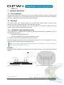
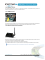
3.10.4 Wireless Radio Modem Installation
Figure 3-62 Wireless Petro-Net Modem
Wireless radio modems can be installed to eliminate the need for a hard-wired Petro-Net connection from the
FIT(s) at the fuel island to the FSC3000 located in a building.
They can also be used to connect between FITs at different fuel islands.
See OPW Manual M00-20-7074 for complete information on the suitability and installation of these modems.
NOTE: Currently, wireless Petro-Net™ is not supported on PetroLink™-enabled systems.
www.opwglobal.com
Doc. #: M1700, Rev. 07
Page 51 of 107
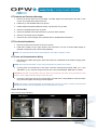
3.10.5 FSC3000 Access Connections — Methods Depending on the type of installation you have, there are multiple methods to connect to the FSC3000.
Remote/Integrated FSC3000 Wired Access Options
Direct Connection
Direct Connect allows you to access
the FSC3000 by serial port. If your PC
lacks a serial port and you are
planning on using a USB-to-Serial
adapter, please call OPW for the
latest recommended USB-to-Serial
adapters. Connect 20-1520-01 cable
RJ-45 connector into port 1 and the
other side into a serial port.
Dial-In Modem Connection
(Universal Socket Modem)
A Dial-In modem allows remote access
by Phone Line. Connect Phone cord into
the Phone Line port and connect to
phone jack. Dial-In modem only supports
analog Phone Lines.
Ethernet Connection
Ethernet connect allows you to
connect to the FSC3000 through the
site’s network. Connect network
cable (not provided) into network
jack. Refer to FSC3000 Ethernet
Port Setup section for configuring the
Ethernet port.
Integrated FSC3000 Wireless Access Options
Integrated FSC3000 Only
Bluetooth®
(Universal Socket Modem)
A Bluetooth® modem allows a PC
equipped
with
Bluetooth®
to
communicate to the FSC3000 without
a hard-wired connection. Requires
Antenna installation.
Integrated FSC3000 Only WiFi
(Universal Socket Modem)
A WiFi modem allows the FSC3000 to
connect wirelessly to a Local Area
Network using standard 802.11b.
Requires Antenna installation.
Remote FSC3000 Cell Modem
The cell modem connects to the
gateway to provide a wireless
connection to the FSC3000.
NOTE: These wireless connections require an antenna to be installed in the top of the cabinet. If an
antenna is not currently installed, please refer to the following installation instructions:
www.opwglobal.com
Doc. #: M1700, Rev. 07
Page 52 of 107
Antenna Installation
The wireless modems above require the installation of an antenna.
1.
Remove all circuit boards to prevent any physical damage to the
electronic components.
2.
Punch or drill a 5/8” hole approximately 1-1/2” from the right and rear
corners of the cabinet.
3.
Remove all metal particles to prevent any damage to the electronic
circuitry.
4.
Insert the antenna, install the hex nut and tighten.
5.
Plug the cable from the antenna into the modem module.
Figure 3-63 Wireless Antenna
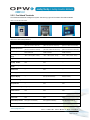
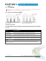
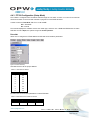
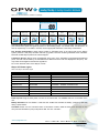
3.10.6 FSC3000 Access Connections — Baud Rate Setting
Set connection baud rate to desired connection rate (default 38400). Unless needed, it is recommended that
the FSC3000 access baud rate be set to 38400 for maximum ARTWare™ performance.
NOTE: When using pass-thru port-connected devices, the FSC3000 access baud rate must be the same
as the device that is being connected to the pass-thru port. If possible, set the device to the highest setting
the FSC3000 supports.
Switch #1. Positions 1-4.
FSC Access Baud Rate (1 & 2 are always closed)
ON
1
2
3
4
38400
ON
1
2
3
4
19200
ON
1
2
3
4
9600
ON
1
2
3
2400
4
ON
1
2
3
4
Figure 3-64 Switch 1 Baud Rate Settings
www.opwglobal.com
Doc. #: M1700, Rev. 07
Page 53 of 107
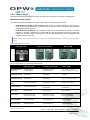
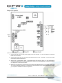
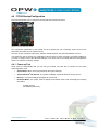
3.10.7 FSC3000 Additional Connections
Figure 3-65 FSC3000 Port Connections FSC3000 Petro-Net Connection (RS-485 port)
Connect FSC Petro-Net cable from FSC3000 RS-485 port to 4x4
Petro-Net junction box cover.
Table 3-5 Petro-Net Connection Parts Description
Part #
FSC Petro-Net™ Cable
20-1443
RS-422 Junction Box cover
20-8035
FSC3000 Journal Printer Connection (RS-232 port 3)
Figure 3-66 Petro-Net Connection All fueling transactions are printed real-time to the journal printer.
Midnight totals print at 12:00 a.m. each day. System log will print
monthly when enabled.
Connect Journal printer into port 3.
Refer to Journal Printer Configuration section for setup of journal
printer parameters.
Table 3-6 Journal Printer Connection Parts
Description
Part #
Journal Printer Cable
20-1517-05
Journal Printer (includes 20-1517-05)
20-7073
Figure 3-67 Journal Printer Connection www.opwglobal.com
Doc. #: M1700, Rev. 07
Page 54 of 107
DPC Interface Connection (RS-232 port 4)
The FSC3000 supports direct pump control for Gilbarco and Wayne pumps. Refer to DPC Installation and
Configuration sections for more information. FSC3000 Host (Network) Modem Connection (RS-232 port 5/6)
The FSC3000 supports a variety of networks. The system can
support up to two (2) network modems (Dual Host). Second host port
is optional.
Connect Host modem to port 5 for single-host modem installation.
Optional second-host modem connection will be in port 6.
Table 3-7 Modem Connection Parts
Description
Part #
Network Modem (includes 20-1517-01)
20-8049
Network Modem Cable
20-1517-01
Figure 3-68 Network Modem Connection
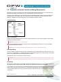
Host (Network) IP Gateway Connection (RS-232 ports 1 and 5)
For some networks, the FSC3000 can use the Internet in place of a
dial-up modem for faster and more reliable card authorization.
An Internet Gateway is used to provide this capability. This same
gateway also provides inbound communication, eliminating the need
for a second Ethernet connection.
First, configure the FSC3000 to communicate on "dial" to the
processor as if you were to use a new OPW modem and phone line.
1.
Connect a serial cable from the host modem port 5 to the IP
Gateway serial port 1.
a.
2.
To use the same Internet connection for inbound
connections, connect a second serial cable from the
COMM port 1 to the IP Gateway serial port 2.
Figure 3-69 IP Gateway Connection
Connect an Ethernet cable (not supplied) from the IP
Gateway to the Internet connection point.
b.
To use phone lines as a backup, connect a phone
line to the IP Gateway.
3.
Power ON and wait for the "status" light to flash green
(approximately once every second).
4.
Run a test transaction for each processor at the site. If the
FSC3000 fails to process cards, make note of the error
received and call OPW Tech Support at 877.697.8324 for
assistance.
5.
Configure the Internet router to "port forward" any traffic for
port 8002 to the IP address of the Gateway Converter.
6.
Test the "call-in" to the OPW FSC3000 using the external IP
address for the site and port 8002.
www.opwglobal.com
Doc. #: M1700, Rev. 07
Page 55 of 107
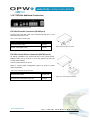
Cell Modem
The cell modem connects to the gateway to provide a wireless connection to the FSC3000.
There are two types of cell modems available for the FSC3000, the 20-6004b for inbound connections only, and
the 20-6000, 20-6001, and 20-6002.
Pass-Thru Connection (RS-232 port 8)
The FSC3000 supports a Pass-thru Connection that allows you to utilize the single-access connection like the
modem to access a second device, eliminating the need for the device to have its own phone line, Ethernet, etc.,
connecting hardware. Future Media Price Sign (RS-232 port 7)
The FSC3000 has the ability to interface to a Future Media price sign. If purchased, plug a 20-1519-01 cable
from port 7 on the FSC3000 to the PriceVision® control unit.
www.opwglobal.com
Doc. #: M1700, Rev. 07
Page 56 of 107
4 System Startup & Testing
WARNING: Double-check the wiring before applying power to the system components. Applying line voltage
to low-voltage inputs will damage the system.
4.1 Startup and Testing
Use the following sections to Startup, Configure and Test all devices.
The FSC3000 is the device that controls the entire system. It is best to have all of the other peripheral devices
configured correctly before programming the FSC3000. The configuration parameters for the K800 Hybrid,
PCT, PCM and DPC are set by DIP switches and/or jumpers. While the C/OPT and FIT500 configuration
parameters are soft settings, meaning they are set through configuration menus instead of switches. The UPC
must be connected to the console or pump controller when started up to synchronize the data between the
devices.
The FSC3000 performs a Cold Start the first time it powers up.
1.
This initializes the system and sets all of the parameters to their default values.
2.
One of the defaults is to enable FIT 1 and PCT 1 positions 1 and 2 for testing purposes only.
3.
The FSC3000 must be configured with the site-specific information using ARTWare™ or CommandLine Programming.
4.
Once all of the other devices are tested, proceed to the FSC3000 Startup, Configuration and Testing
section.
Follow the appropriate sub-sections below based on the type of devices installed:
5.
If multiple devices such as FITs and/or Pump Control are used, each device in that group must have a
unique address and the same communication parameters.
6.
The default is 9600 baud, 7 Data Bits, even parity.
7.
Use the following Quick Reference charts for Petro-Net communication-parameter setup.
Table 4-1 Petro-Net Communication Parameters
Fuel Island Terminal/PetroLink™ K800 Hybrid C/OPT FIT500 EPC (VIT emulator) Address DIP Switch Terminal Setup Mode Terminal Setup Mode Configuration File Baud Rate Fixed 9600 Terminal Setup Mode Terminal Setup Mode Configuration File Pump Control K800 Hybrid PCT PCM UPC DPC Address DIP Switch DIP Switch DIP switch (Emulates PCT 1 -‐ 4) N/A Baud Rate Fixed 9600 DIP Switch Toggle Switch N/A NOTE: On DIP switch-equipped boards, any change after “power-up” will require a power cycle or reset (if
board is equipped).
www.opwglobal.com
Doc. #: M1700, Rev. 07
Page 57 of 107
4.2 K800 Hybrid Startup/Configuration
This section describes how to configure and verify that the terminal is functional.
4.2.1 Configuration (DIP Switches & Jumper)
Figure 4-1 K800 Hybrid Switch 1 Settings
Jumper #1
Set Jmp1 to the AMX position.
Switch #1
Positions 1-4: Place the pump/dispenser in manual override.
Positions 5-8: These are set to match the electrical output of the pulser attached. Active pulsers supply a lowvoltage signal to the PCT board. Passive pulsers either contain switch contacts or have open collector
transistor outputs.
Table 4-2 Jumper 1, Switch 1 Positions 1-8
Switch #1 Positions 1-8
Switch Position
Pump Position
1
1
2
2
3
3
4
4
5
1
6
2
7
3
8
4
Description
Setting
Normal Operation
Manual Override
Normal Operation
Manual Override
Normal Operation
Manual Override
Normal Operation
Manual Override
Active
Passive
Active
Passive
Active
Passive
Active
Passive
OPEN
CLOSED
OPEN
CLOSED
OPEN
CLOSED
OPEN
CLOSED
OPEN
CLOSED
OPEN
CLOSED
OPEN
CLOSED
OPEN
CLOSED
www.opwglobal.com
Doc. #: M1700, Rev. 07
Page 58 of 107
Switch #2
Positions 1-3: Determine the Petro-Net address for both the FIT and PCT functions of the K800 Hybrid.
Table 4-3 Jumper 1, Switch 2 Positions 1-3
Switch #2 Positions 1-3 (FIT/PCT Address)
FIT/PCT #1
ON
1
2
3
FIT/PCT #2
ON
1
2
FIT/PCT #3
3
ON
1
2
3
FIT/PCT #4
ON
1
2
FIT/PCT #5
3
ON
1
2
FIT/PCT #6
3
ON
1
2
3
FIT/PCT #7
ON
1
2
3
FIT/PCT #8
ON
1
2
3
Position 4: Defines the type of reader installed on the FIT.
Position 5: Defines if the user will be allowed to enter his card number after three bad reads.
Position 6: Determines which mode the K800 Hybrid is in: Operational or Test.
Position 7: Is set to match the type of pulser that is connected. Mechanical pulsers have switches that open
and close with each pulse. Electronic pulsers typically have shutter wheels and optical detectors. Mechanical
pulsers cannot count as fast and generate more electrical noise. Setting position #7 to “Mechanical” setting
filters the input signal.
Position 8: Must always be set to closed.
Table 4-4 Jumper 1, Switch 2 Positions 4-8
Switch # 2 Position 4-8
Switch Position
Description
4
Reader Type
5
Manual Card # Entry (after 3 bad reads)
6
Test Mode
7
Pulser Type (Pump Positions 1-4)
Setting
ChipKey
OPEN
Magnetic Card
CLOSED
Disabled
OPEN
Enabled
CLOSED
Operational Mode
OPEN
Test Mode
CLOSED
Mechanical
OPEN
Passive
CLOSED
www.opwglobal.com
Doc. #: M1700, Rev. 07
Page 59 of 107
4.2.2 Power-Up Test
The K800 Hybrid terminal displays the software version and reader type, then runs a RAM and EPROM test.
If switch SW2 position 6 is set to open, the system will go into normal operation.
4.2.3 Display Contrast
To compensate for different levels of ambient light, you can adjust the display contrast with controls on the
PV247 FIT/PCT board.
Use a small screwdriver to adjust the display contrast potentiometer (middle potentiometer).
4.2.4 FIT Test Mode
The system will enter the test mode upon power-up if the test switch is closed (SW2 position 6). The test mode
displays five (5) separate tests.
Press the <ENTER> key to select the displayed test or press the <CLEAR> key to advance to the next test.
These are the five tests:
•
Keyboard: Keys pressed are echoed on the display.
•
Stop Button: Test the function of the emergency stop or alpha button.
•
Display: Scrolls characters on the LCD display.
•
Reader: Reads and displays the information coded on the card/key being tested.
•
DIP Switch: Shows the state of the eight (8) positions of switch SW2.
4.2.5 PCT Testing
1.
Activate the Bypass switch for the first hose position (Switch 1, Position 1).
2.
Observe the red “Relay” LED that comes on.
3.
Activate the pump/dispenser and watch the yellow “In Use” LED and verify that it comes on after the
reset cycle completes and the pump motor/solenoid is energized.
4.
Dispense product and watch the green “Pulse” LED. It should flash as product is dispensed.
5.
If everything checks out OK, turn off the bypass switch and repeat for each hose position to which the
system is connected.
Table 4-5 Pump Relay LEDs
Pump Position 1
Pump Position 2
Pump Position 3
Pump Position 4
Relay LEDs
Relay ON (RED)
In-Use (Yellow)
Pulse (Green)
www.opwglobal.com
Doc. #: M1700, Rev. 07
Page 60 of 107
4.3 C/OPT Startup/Configuration
This section describes how to configure and verify that the terminal is functional.
Figure 4-2 Verify C/OPT Connections
The configuration parameters for the C/OPT are set by placing the unit into test/setup mode.
Once set, the parameters are retained in non-volatile memory.
•
•
•
The units are pre-configured at the factory based on the options installed.
The Petro-Net address is set to 1.
You should not need to change any configuration options unless you have more than one C/OPT
installed, or you want to change some of the advanced settings.
NOTE: In which case, refer to the C/OPT Setup and Configuration sections to make the necessary
changes.
4.3.1 Power-up Test
These tests run automatically after you turn ON your C/OPT. The tests also run before the unit enters
test/configuration mode.
Display Initialization: Video RAM test, during which the graphics display shows vertical lines.
System Configuration: In the prompt below, Version is the test/configuration software version.
Keypad type (REG=regular), display type (GRAPH=graphic) and reader type (MOTOR=motorized) are also
shown.
Version: 03.01G
REG GRAPH MOTOR
Flash Checksum Test. ROM (read-only memory) test. Display will show:
FlashBoot: ####
Appl: ####
RAM Test. Non-destructive test (that is, when memory is not erased) of the random access memory.
This test takes about 10 seconds; a character "spins" on the display during the test. Press <CLEAR> to bypass
this test. Depending on how the test ends, you will see one of the following:
BREAK - The (CLEAR) key was pressed.
PASSED - RAM is OK.
ERROR # Test failed at indicated memory location.
www.opwglobal.com
Doc. #: M1700, Rev. 07
Page 61 of 107
4.3.2
Display Contrast
To compensate for different levels of ambient light, you can adjust the display contrast with the controls on the
upper PC board. Depending on your display type (below) adjust either the CONTRAST UP/DOWN switches or
the contrast potentiometer.
For systems with the standard graphics display, hold the toggle switch on the lower PC board to the left or right
to adjust the contrast. This toggle switch is also used to enter the C/OPT Configuration Mode.
NOTE: If your system has the optional 2x20 character display, use a small screwdriver to adjust the
potentiometer on the bottom PC board.
4.3.3 C/OPT Receipt Printer Option
NOTE: The part number to order the C/OPT Receipt Printer Option is p/n: 20-4339.
Table 4-6 Printer Options Part Numbers
Quantity
Part Number
Part
1
75-0124-12V
C/OPT Printer 12 VDC
1
20-1679
Modified Data Cable
1
20-1677
Modified Power Cable
1
280-007
Cable Tie
1
50-3203
Adapter Block
2
50-0391
Screw 10-32 x 0.500 PHIL PH ZP
4
50-0229
Screw 8-32 x 5/8 PHIL PANHD
1
54-1106
Thermal Paper 4" Dia. Roll
1
50-2127
Cable Clamp
C/OPT Printer Sub-Assembly
(p/n: 20-6203)
Shaded rows are the parts required
for a C/OPT Printer (12 VDC)
replacement.
During receipt-printer installation, please refer to the below image for mounting orientation.
Figure 4-3 C/OPT Receipt Printer Assembly
www.opwglobal.com
Doc. #: M1700, Rev. 07
Page 62 of 107
Installing the C/OPT Receipt Printer
1.
Position the adapter block on the printer mounting area.
2.
Screw the adapter block in place using the four supplied 8-32” x 5/8" PHIL PANHD screws.
NOTE: Observe correct adapter block orientation by referring to Printer Assembly.
Figure 4-4 Printer Data and Power Cable Connections to
PV343 Board
3.
Position the printer unit to align with the inner screw holes of the adapter block.
4.
Mount the printer to the adapter block using the two supplied 10-32” x 1/2" PHIL PH ZP screws.
5.
Mount the supplied cable clamp utilizing the screw located above and to the right of the newly installed
printer on the enclosure door.
6.
Route the data cable through the cable clamp and connect the data cable to the PV343 board
J1/Printer socket.
7.
Route the power cable through the cable clamp and connect the power cable to the PV343 board
J6/RS232-A socket.
8.
Mount the cable clamp securely to the enclosure door using the screw located in Step 5.
Receipt Paper Loading Instructions
The optional receipt printer accepts metric-sized thermal paper 58 mm or 60 mm width and 102 mm in
diameter.
1.
Turn ON the C/OPT unit by locating the power supply in the left-rear corner of the upper enclosure, via
the red toggle switch.
2.
Remove any packaging material from the roll of paper and place the roll of 4" (10.2 cm) diameter
paper in the paper tray.
NOTE: Paper must feed from the TOP of the roll.
3.
Feed the paper into the printer by inserting the paper through the paper guide slots. The sensor in the
paper guide will detect the paper.
4.
Cut off the extra paper appearing in the eject chute by pulling it out.
5.
Your receipt printer is ready for use.
www.opwglobal.com
Doc. #: M1700, Rev. 07
Page 63 of 107
Clearing Paper Jams
In order to clear a paper jam, detach the document that is presently jammed in the eject chute and remove the
paper. In order to properly remove the remaining paper in the chute, perform the following steps.
1.
Turn the unit OFF before clearing the paper jam.
2.
Press the paper release lever as see in the following images.
Figure 4-5 Paper Loading Instructions (printer top view)
Figure 4-6 Printer Release Lever (side
view of printer)
NOTE: Never actuate this lever during printing operation or damage will be caused to the printer head.
3.
4.
5.
6.
7.
8.
Manually pull the paper out of the printer chute.
If paper remains in the print mechanism and the eject chute this can be removed by pulling the right
hinge pin (opposite the wire routing of the chute sensor).
Tilt the printer open.
Eject the paper by twisting the motor-pinion gear clockwise until the paper is available to be removed
manually. See below the image on the left showing the top view of the receipt printer.
Now that the printer is cleared of the paper jam, tilt and replace the printer mechanism back into
normal operating position.
Secure the printer mechanism by pushing the hinge pin back into its operating position.
www.opwglobal.com
Doc. #: M1700, Rev. 07
Page 64 of 107
4.3.4 Configuration (Setup/Test Mode)
The C/OPT is configured with commands issued through the unit itself. Several of the tests are also self-tests
performed automatically at power-up.
When not in Privileged Mode you will only be able to perform a test and/or view settings.
NOTE: To modify configuration you must be in Privileged Mode.
To easily identify which commands require Privileged Mode for configuration change, they will be identified
after the command with “Privileged” following it.
1.
2.
Password
Display
3.
4.
5.
6.
7.
8.
9.
10.
11.
12.
13.
14.
15.
16.
17.
18.
19.
20.
Keypad (Configure Optional Alpha Keypad, if installed)
Door
Reader (Configure Readers Installed)
Printer (Configure Receipt Printer)
Ports (Configure Petro-Net Communication Parameters)
Lights
Beeper
Poll ID (Configure C/OPT (FIT) Address)
Toggle (Configure Miscellaneous Features)
Value (Configure Miscellaneous Features)
RAM
FLASH
EPROM
VERSION
RUN APP
FACTORY
I/O
DEBUG
Red & Underlined indicates the minimum required setup.
Enter Configuration Mode
1.
Turn the unit power switch OFF.
2.
Hold the CONTRAST UP or DOWN, push button on the PC board.
3.
Turn the unit power switch ON.
4.
After you hear two beeps, release the button.
5.
Unit will cycle through power-up test then show Password screen.
NOTE: This mode gives you access to the following areas of C/OPT operation. Setting most of these
functions requires PRIVILEGED access; see "1. PASSWORD (Privileged)" instructions.
www.opwglobal.com
Doc. #: M1700, Rev. 07
Page 65 of 107
1. PASSWORD (Privileged)
You must enter Privileged Mode to configure password parameters.
1.
When the Privileged Mode is ON, the C/OPT displays a "P" in the upper-left corner of the display.
2.
The "P" comes before the title of the menu display.
3.
When not in Privileged Mode, the Password function prompts for a password entry.
4.
The factory-set password is 0000, which you should change as soon as possible.
5.
If you enter the wrong password, a 15-digit number appears on the display.
6.
If you have lost the unit’s password, call Petro Vend Tech Support, and supply them with the 15-digit
number.
7.
If you have proper ID, OPW will supply the password for that unit.
In order to change the password, you must first enter Privileged Mode.
From first powering up, perform the following sequence to change your password.
1.
2.
3.
4.
5.
6.
PASSWORD: press <Y E S > or <E N T E R >
Enter 0000: press <E N T E R >
P1 – PASSWORD: press <E N T E R >
PASSWORD Set?: press <Y E S > or <E N T E R >
New: [enter up to four (4) digits here] press <E N T E R >
Verify: [re-enter same four (4) digits] press <E N T E R >
7 . Password Changed: press <NEXT>
To leave Privileged Mode, you must cycle power to the C/OPT, or enter the application program with 17 RUN APP.
2. DISPLAY
Use this function to adjust the contrast of the display and test the display itself.
CAUTION: Do not change the display SLOPE setting. Press “No” ONLY!
The C/OPT uses three (3) readings to adjust the contrast of the display:
1.
The C/OPT calculates Best Contrast from the display temperature located on the front of the display.
2.
The System Contrast is set manually by using this Configuration/Test function, or by using the switch
on the PC Board. The first prompt asks you if you want to manually adjust System Contrast:
ADJUST CONTRAST press <YES> or <ENTER>
DISPLAY-9
3=LIGHT 6=DARK
Adjust contract by pressing 3/Light to brighten or 6/Dark to darken the display.
3.
You can also use the graphics contrast SW1 & SW2 to adjust the Graphics Display Contrast or the
Character Display Potentiometer on the PC board to adjust the contrast of the Character Display.
Press <YES> or <ENTER> to accept entry and move to the Test Fan function.
FAN OFF
3 = ON
6 = OFF
Press 3/ON to turn ON or 6/OFF to turn OFF the fan.
www.opwglobal.com
Doc. #: M1700, Rev. 07
Page 66 of 107
NOTE: A small fan can be activated to circulate air around the graphics display to stabilize display contrast.
To enter the [Debug Display] function:
Press <YES> or <ENTER> to accept entry. Enabling this feature displays two rows of numbers on the bottom
of the graphics display. The numbers (used in troubleshooting the C/OPT) are for use by qualified service
personnel.
C/OPT Debug ON? press <YES> or <ENTER>
To turn OFF the debug display: enter <NO> at the [Enable Debug?] prompt
Graphic Display ONLY:
You can set the graphics display to show light characters on a dark background, as opposed to the default dark
characters on a light background.
Change INVERSE? press <YES> or <ENTER>
Disable INVERSE? press
<NO> or <CLEAR>
To cancel command* press <YES>
NOTE*: The display is now inverted. To invert it again, repeat this procedure.
To enter the [Test Display?] function:
If you press <YES> at the [Test Display?] prompt, the graphics screen displays all characters of the alphabet,
in upper and lower case, along with all punctuation. The characters are written line after line until the screen is
filled, at which time the process begins again, overwriting the previous screen.
To end the test, press any key or function button
Then, to move to the keypad test: press <NEXT>
3. KEYPAD (Privileged)
This test checks the operation of the keys on the standard numeric keypad or the optional alpha keypad
(Keypad 2). To begin the test, press <YES > or <ENTER> at the 3 - KEYPAD prompt.
ALPHA
Change Keypad2?: press <YES>
This is telling you an alpha keypad is installed as KEYPAD 2, and asking if you want to change it.
To list Alpha, Numeric, Alphanumeric or None: press <NO> or <CLEAR>
When the desired type is shown: press <ENTER> to select it
To test the keys: press <TEST>
Then press any key on the keypad except <ENTER>, which exits the test mode.
The key you press appears briefly on the display to show you the key is physically and electronically functional.
The top three function buttons appear as F1, F2 or F3. The bottom function button exits the test.
To end the test: press <EXIT> or <CLEAR>
Then, to move to the door test: press <NEXT> or <CLEAR>
4. DOOR
This test both checks the operation of the door-position sensors and lets you enable or disable the
electromagnetic “catch” that keeps the door open until a transaction is printed or a card is read.
To begin the test: press <YES> or <ENTER> at the 4-DOOR prompt
P DOOR <YES>
Door Flap: OPEN
www.opwglobal.com
Doc. #: M1700, Rev. 07
Page 67 of 107
NOTE: This is the current position of the door.
Should door stay open: hold 3 for <YES> or 6 for <NO>
Prompt will ask, [Test door?]: press <YES> to raise and lower door manually, screen
should show OPEN and CLOSE transition
To move to the Reader test: press <EXIT> and then <NEXT>
5. READER (Privileged)
This test checks operation of the standard "push-pull" card reader. Also, while in Privileged Mode you can
change what type of reader the C/OPT is equipped with.
NOTE: Use if updated from "push-pull" reader to a ChipKey® optical. Use "push-pull" for proximity
readers.
P READER YES
Push-Pull
Change Reader 1(NO)
Toggle to Reader 2, then press <YES>
Push-Pull
Change Reader? YES
Toggle through types with the NO function button, and then press <ENTER> to set that type.
NOTE: If a second reader is not installed, disable Reader 2 by selecting [Reader 2] and type <NONE>.
Part one of this test checks the operation of the two sensors in the card reader:
•
A front sensor that detects initial card insertion
•
A back sensor that confirms complete insertion
Check the reader with no card inserted and a card totally inserted.
To test the sensors and read heads:
Read SENSORS 1 YES
Frt = Off Bck = Off EXIT
Or, insert a card into the reader. The status of the sensors should change: Frt changes to ON; and when the
card is all the way in, Bck goes ON as well.
The prompts are repeated for Reader2 sensors:
Test READER1 YES
Testing Reader/
Insert Card
Insert a card into the reader. The status of each track is displayed:
•
INCORRECT READING shows a card-read error.
•
CARD ORIENTATION means no data was obtained from the card—check for proper insertion
direction.
•
ORIENTATION may appear briefly before track data is displayed.
If a good read is done, another screen appears with the data on the card.
Use (1) key (or the LEFT function button) to scroll left. Use (3) key (or the RIGHT function button) to scroll right:
<- 1 Track 2 ->
1234567890123456
Press <ENTER> (or the EXIT function button) to go to the Reader2 test (if applicable).
www.opwglobal.com
Doc. #: M1700, Rev. 07
Page 68 of 107
Press <EXIT> and then <NEXT> to move to the Printer test.
6. PRINTER (Privileged)
This test checks the receipt printer:
The first prompt is to [Change Print?]
Press <YES> or <ENTER> to begin the printer configuration.
The next prompt you see is [Enable Print?] (Requires Privileged Access)
To disable the printer (prevent it from printing receipts), press <NO> or <CLEAR> to toggle the status.
Press <YES> or <ENTER> to accept.
If the printer is enabled, a sample receipt is printed:
Print Test Receipt
SYSTEM CONFIGURATION
S/W Ver: 04.02.L
Lib Ver: 01.02I
H/W FPGA 1: 4
H/W FPGA 2: 2
H/W Read 1: 7
H/W Read 2: 7
Rd1: Push-Pull
Rd2: None
KP1: Regular
KP2: Alpha
Display: GRAPHIC
Dsp Cntrst: -11
Dsp Volts : 793
Dsp Temp : 1023
ID:65, 0x41, A
: 9600,7,E, 1,-,T
Prn Cntrst: -1
Chute: Enabled
Prn Chute : 250
Chute AtoD: 973
Prn Head : 624
Toggle : ABCD EFGH IJKL MNOP
1010 1010 1110 1010
Value A:
0
N: 0300
Value B:
0
O:
0
Value C:
0
P:
0
Value D:
0
Q:
0
Value E:
0
R:
0
Value F:
0
S:
0
Value G:
0
T:
0
Value H:
0
U: ****
Value I:
0
V: ****
Value J:
0
W: ****
Value K:
0
X: ****
Value L:
0
Y: ****
Value M: 0 Z: ****
Beeper:4150 Freq4 Duration
Cheksum:9ecd Boot pass431 Appl pass
Change Chute
In order to enable or disable the sensor in the printer chute, Privileged Access is required. Current status is
shown with prompt [To Change?].
Press <Yes> to change status.
www.opwglobal.com
Doc. #: M1700, Rev. 07
Page 69 of 107
Sensors
This part of the test checks the current condition of the three sensors mounted on various parts of the printer
assembly. Follow the keystrokes and display sequence below:
Test SENSORS? YES
1.
Paper-Low: YES or NO
If YES, the sensor is not seeing enough paper.
Test the sensor by raising and lowering the paper roll from its holder. The reading should change from
NO to YES. Reloading paper in the printer should change the reading to NO.
Press <ENTER> to move to the next test.
2.
Paper-Out: YES or NO
If NO, this sensor sees paper. To test, press the paper release switch and remove the paper from the
printer.
Press <ENTER> to move to the next test.
3.
Chute: EMPTY or FULL
If chute sensor is disabled, you see [CHUTE N/A].
If the sensor is enabled and you see [EMPTY] the sensor is not seeing a receipt in the discharge
chute.
Push paper from the roll into the receipt chute. The sensor status should change to FULL.
Press <ENTER> to move to the next test.
Error Message Codes
Table 4-7 Error Message Codes
2
Paper Blocking Printer Chute
4
Temperature Error - Print Head Overheated
8
Printout Lost - Some Error Occurred During Printing Causing a Failure
16
Paper Jam Detected
18
Paper in Chute and Jam Detected
64
Paper Out
72
Paper Out and Print Lost
88
Paper Jam, Printout Lost and Paper Out Detected Conditions
90
Chute Blocked, Paper Jam, Printout Lost and Paper Out Detected Conditions
www.opwglobal.com
Doc. #: M1700, Rev. 07
Page 70 of 107
7. PORTS (Privileged)
Use this function to configure COM 1 (Petro-Net) and to actively test communication flow into and out of the
port.
COM 1 DEFAULTS (SYSTEM2): 9600, 7, E, 1, --, T
Perform the following sequence to set up the COM 1. (The values shown are system defaults.)
To exit from a screen with no “Exit” key, press <YES>, and then answer <NO> to the [Save?] Prompt.
P PORTS YES or ENTER
COM1
Set?
9600, 7, E, 1,
Press <YES> to move from Baud Rate, to Data Bits, to Parity, to Stop Bits, to CTS and, finally, to RTS (each is
explained below).
COM1
Baud
9600, 7, E, 1,
Press <NO> to toggle through Baud Rates. Press <YES> to accept value and go to Data Bits.
COM1
Data
9600, 7, E, 1,
Press <NO> to toggle between 7 and 8 Data Bits. Press <YES> to accept value and go to Parity.
COM1
Parity
9600, 7, E, 1,
Press <NO> to toggle through Parity Choices. Press <YES> to accept value and go to Stop Bits.
COM1
Stop
9600, 7, E, 1,
Press <NO> to toggle between 1 and 2 Stop Bits. Press <YES> to accept value and go to TX-RTS.
COM1
TX-RTS
9600, 7, E, 1,
Press <NO> to enable or disable TX line control of RTS signal. Press <YES> to accept value. This is the final
parameter.
Press <YES> or <ENTER> to Save; press <NO> to Cancel.
The [TEST?] prompt will appear. To test communication port press <YES>; otherwise, press <NO> to exit.
NOTE: Unit must be disconnected from Petro-Net wiring for test to successfully run.
Press <NEXT> or <ENTER> to move to the next function.
www.opwglobal.com
Doc. #: M1700, Rev. 07
Page 71 of 107
8. LIGHTS
This function selects [Pocket Light OFF] or [Pocket Light ON]. The pocket light is the light over the keypad.
This function also tests the lights.
In Privileged Mode, use the following key sequence:
P
LIGHTS YES
LIGHTS: HIGH
3 = HIGH
6 = LOW
HIGH is ON
LOW is OFF
Press function button <HIGH> or <3>; <LOW> or <6> to turn light ON or OFF. Then press the <EXIT> function
button.
Finally, press <NEXT> to move to the [9 - Beeper] test.
9. BEEPER (Privileged)
This function lets you listen to the beeper tone, or change the tone to suit your own preferences. The tone
occurs each time a key is pressed.
To confirm operation, a beeper test plays a song through the beeper, or speaker, that is attached to the SPKR
connector on the C/OPT board.
To set the beeper tone:
BEEPER YES
Set? YES
Frq: 4150 Dur: 4
These are the current beeper frequency (in Hz) and duration (in system ticks, 61 ticks equals one second).
Enter a new frequency (from 65 Hz to 5,000 Hz) and duration (from 1 to 32 ticks). Then press <YES>.
Press the <TEST> function key to play a song to test the beeper. When the tune has finished playing, press
<EXIT> to exit the beeper test and go to the [Poll ID] test.
10. POLL ID (Privileged)
This function gives the C/OPT a unique polling address for access by your fuel site controller.
The FSC3000 recognizes C/OPT Poll IDs according to the following table:
Table 4-8 C/OPT Poll IDs
C/OPT #
1
2
Poll ID
65
66
3
4
5
6
7
8
67
68
32
33
34
35
To change the Poll ID, complete the following steps:
P 9 - POLL ID YES or ENTER
POLL ID Set?
{nnn} , {hhhh} , a YES or ENTER
www.opwglobal.com
Doc. #: M1700, Rev. 07
Page 72 of 107
The "nnn" is a three-digit number. The "hhhh" is the hex-equivalent of the number. The "a" is the ASCII
character represented by the three-digit number:
ASCII #:
Here, enter a number from 000 to 255 and press <YES> or <ENTER>. The number, hex number and ASCII
characters appear.
{nnn} , { hhhh} Save?
<YES> or <ENTER>, and then <EXIT> or <CLEAR> to move to the [Toggle] function.
11. TOGGLE (Privileged)
The C/OPT has 16 toggles with letters A-P used for special functions. Below is a table defining each toggle's
function.
CAUTION: Only system programmers should use toggle functions.
Each toggle can be set ON or OFF. The default is all switches are set to OFF.
To change switch settings:
P 8 – TOGGLE <YES> or <ENTER>
A: Off
To turn Switch A ON, press function button <SET?> or <ENTER>.
Then, press <NO> or <CLEAR> to change OFF to ON. Next, press <YES> or <ENTER> to confirm your
choice.
Repeat this process for all required toggle changes, with the process described for Switch A. When done, press
<NEXT> or to go to the [Value] function.
Table 4-9 Toggle Functions
VALUE
DEFAULT
FUNCTION
A
OFF
Remove current date on receipt – Proprietary cards only
B
OFF
Remove current time on receipt – Proprietary cards only
C
OFF
Send Magnetic Card Track 1 data to the fuel site controller
D
OFF
Enable Read/Write ChipKey support
Enable replace Track 2 with Track 1 function.
E
OFF
When enabled, C/OPT will only read Track 1 data and modify it to match Track 2
format. All alpha characters are stripped from the data, the STX is converted from a %
to “;”, and the field separators are changed from “^” to “=”.
F
OFF
Enable advance multi-receipt algorithm
G–P
OFF
Not Used – Leave “0”
www.opwglobal.com
Doc. #: M1700, Rev. 07
Page 73 of 107
12. VALUE (Privileged)
The C/OPT has 26 numbers (values) used for addition functions. As the table below indicates, each value is
assigned a letter from A to Z.
Table 4-10 Value Functions
VALUE
DEFAULT
FUNCTION
A
0
Graphics ID
“0” = Standard
“1” = Chevron
“2” = Irving
B
0
Receipt Copies
“0” or “1” = 1 copy
“2” thru “x” = 2 to x copies
C
0
Number of Bad Reads before keyboard entry is permitted
D
0
Receipt Symbol
“0” or “36” = American Dollar
“156” = British Pound
E–F
0
Not Used – Leave “0”
G
0
Dedicated Pump Number “0” = prompt for pump #
H
0
Door Delay (seconds)
I–J
0
Not Used – Leave “0”
K
0
Time-Out for next receipt (seconds) – Chute sensor must be enabled
L
0
Not Used – Leave “0”
M
0
Maximum line length of receipt values from 30 to 40
N–T
0
Network number
U–Z
0
Hidden network number
The value can be an integer from 0 to 65535. Codes "N" through "Z" are daily password-protected and
additionally codes "U" through "Z" are hidden.
Use <PREV> and <NEXT> to move through the letters.
NOTE: If a value between N and Z is selected, a 15-digit number appears. Call the OPW Technical Service
Department and give them the 15-digit number. They will decode the number and give you the daily
system password. Altering these VALUES must be approved by OPW.
P - VALUE <YES> or <ENTER>
400 SET?
Press <YES> or <ENTER>.
Enter A:
Enter an integer from 0 to 65535, then press the <ENTER> key.
Set?
Press <YES> or <ENTER>, then press <NEXT> or <ENTER>. To abort, press <CANCEL> or <CLEAR>.
B:
0
etc....
Enter new values as desired. To skip a letter press <NEXT>. To leave this mode press <CANCEL>.
www.opwglobal.com
Doc. #: M1700, Rev. 07
Page 74 of 107
13. RAM
This test performs a non-destructive test of the C/OPT random access memory. To run the RAM test, press
<YES>. A character spins around to show the test is in progress. The test lasts approximately 15 seconds.
Once the test is complete, the screen will show PASSED. Press <EXIT> and then <NEXT> to move to the
[ROM (BOOT)] test. If the screen shows BREAK, then the CLEAR key was pressed and the test was
interrupted. If the following [ERROR (followed by a memory address)] the RAM test failed.
14. FLASH
This test performs a checksum test of C/OPT flash memory. The flash memory test is a checksum test of the
boot program and application program. To check the ROM, press <YES>. The test should not take longer than
two seconds.
When test is complete, press <EXIT> and then <NEXT> to move to the [EPROM] test.
15. EPROM
This test checks the C/OPT program by performing a non-destructive test on the erasable programmable readonly memory. To check the application program, press <YES>. The [Memory is OK] prompt should appear;
the test should not take longer than two seconds.
When test is complete, press <EXIT> and then <NEXT> to move to the next test.
16. VERSION
Displays the version of the test/configuration firmware in the C/OPT along with the current system
configuration: keypad type, display type and card reader type.
To check the C/OPT version, press <YES>. Press <EXIT>, and then <NEXT> to go to [Run App] option.
17. RUN APP
This function can exit the test mode, and launches the C/OPT application program. Or, if using Privileged
Access, this function is used to allow downloading of the C/OPT application software.
NOTE: For the procedure to download application software, contact OPW Tech Support.
18. FACTORY (Privileged)
Restores factory default values to the entire C/OPT configurable parameters.
FACTORY YES
Restore data to factory settings?
Press <YES> or <ENTER> to restore factory settings, or press <NO> to abort. From here, the procedure differs
depending on the C/OPT software level.
NOTE: Cycle C/OPT power to initiate factory defaults.
19. I/O
This is a troubleshooting tool, for OPW service personnel only.
20. DEBUG
This is a troubleshooting tool, for OPW service personnel only.
www.opwglobal.com
Doc. #: M1700, Rev. 07
Page 75 of 107
4.4 FIT500 Startup/Configuration
This section describes how to configure and verify that the terminal is functional.
Figure 4-7 Verify FIT500 Connections
The configuration parameters for the FIT500 are set by placing the unit in test/setup mode. Once set, the
parameters are retained in non-volatile memory.
The units are pre-configured at the factory based on installed options. The Petro-Net address is set to 1.
You should not need to change any configuration options unless you have more than one FIT500 installed, or
you want to change some of the advanced settings. In this case, refer to the FIT500 Setup and Configuration
sections to make the necessary changes.
4.4.1 Power-up Test
These tests run automatically after you turn ON your FIT500. The tests also run before the unit enters
test/configuration mode.
•
System Beep: When unit is first powered-up the system will beep.
•
System Windows® CE Boot-Up: The system will display a quick Windows CE boot-up screen.
•
Boot-Up: A car with a stoplight will appear for one second.
•
Download Mode: The system will then display the download screen and will display the following
information:
Loading (version)
FIT (address) (baud rate)
www.opwglobal.com
Doc. #: M1700, Rev. 07
Page 76 of 107
4.4.2 Receipt Printer Paper
The optional receipt printer accepts metric-sized thermal paper.
Maximum paper roll diameter is 4" (102 mm). A prompt displaying [Low paper] will appear when the diameter
of the paper roll is lower than 1.6" (40 mm). Paper-roll width must be 2.3" (59 to 60 mm).
The following figures show how to load a new roll of paper in the printer, followed by step-by-step instructions:
Figure 4-8 FIT500 Receipt Printer
These instructions assume the unit is open and turned ON. Before first use, remove packing material from
around the printer.
1.
Pull open the receipt printer door.
2.
Remove the core of the preceding roll, if necessary.
3.
Place the new roll.
4.
Set the paper end through the door chute over the platen.
5.
Close the door, keeping the paper end tight to avoid a possible paper loop.
6.
Pull the paper end to cut it; the paper is loaded.
www.opwglobal.com
Doc. #: M1700, Rev. 07
Page 77 of 107
4.4.3 FIT500 Configuration (Setup Mode)
The FIT500 is configured with commands issued through the unit itself, so there is no need for an external
terminal connection to one's fuel site controller to program for most FIT500 functions.
In order to enter the Test Mode, SW1 Pos 1 must be OFF.
Off = Test Mode
On = Normal
The terminal displays the software version and reader type, and then runs a RAM and EPROM test. If switch
SW2 Pos 6 is set to Open, the system will go into normal operation.
Petro-Net
Allows one to configure the FIT500 address and RS-485 communication parameters. Figure 4-9 Petro-Net Setup
Use table below to set the proper address: Table 4-11 Petro-Net FIT Address
FIT #
Address
1
65
2
66
3
67
4
68
5
32
6
33
7
34
8
35
Set Petro-Net communication parameters to match FSC3000.
Table 4-12 Petro-Net Communication Parameters
Baud
Parity
Data Bits
Stop Bits
9600
Even
7
1
www.opwglobal.com
Doc. #: M1700, Rev. 07
Page 78 of 107
Display
Figure 4-10 Display Setup
Allows one to adjust background contrast and display brightness.
Default Display Brightness:
Day: 25
Night: 50
NOTE: Background (color) will only apply to screens without graphic images.
Printer
Figure 4-11 Printer Setup
This function configures the printer.
www.opwglobal.com
Doc. #: M1700, Rev. 07
Page 79 of 107
Value
The FIT500 has 26 values for special functions.
Below is a table defining each value’s function.
NOTE: All values default to zero.
Table 4-13 Value Functions
Value
Function
A
N/A
B
Receipt Copies
0,1 = 1 copy
2-up = that number of copies
C
# of Bad Reads Before Permitting
Keyboard Entry of Card #;
0 = Disabled
D
Receipt Symbol
0,36 = $, 156 = £
E–F
Leave 0
G
Dedicated Pump Number;
0 = Disable
H–M
Leave 0
N–T
Network Number
U–Z
Network Number (Hidden)
Figure 4-12 Value Setup Toggles
The FIT500 has 16 toggles for special functions.
Below is a table defining each toggle’s function.
Modify toggles as needed.
NOTE: All values default to zero.
Table 4-14 Toggle Functions
Value
Function
A
Remove Current Date on Receipt
(Proprietary Cards Only)
B
Remove Current Time on Receipt
(Proprietary Cards Only)
C
Send Track 1 to FSC3000
D
Not Used - Leave Unchecked
E
Leave 0
F-P
Not Used - Leave Unchecked
Figure 4-13 Toggle Settings
www.opwglobal.com
Doc. #: M1700, Rev. 07
Page 80 of 107
4.4.4 Test Mode
The system will enter the test mode upon power-up if the test switch is closed (SW2 Pos 6). The test mode
displays five separate tests. Press the <ENTER> key to select the displayed test or press <CLEAR> key to
advance to the next test.
The FIT500 has a variety of tests to troubleshoot the system. From this main menu you will be able to select
from the following test below:
Display Test
This test checks the operation of the display.
1.
àDisplay, from the main menu.
Click Testsà
2.
The system will run through a variety of display tests.
Figure 4-14 Tests Menu Selection
Reader Test
This test checks the operation of the Magnetic reader.
1.
àReader, from the main menu.
Click Testsà
2.
Data from Tracks 1 & 2 will be displayed when a card is swiped.
Figure 4-15 Reader Test
www.opwglobal.com
Doc. #: M1700, Rev. 07
Page 81 of 107
Keyboard Test
This test checks the operation of the keys on the standard numeric and/or option alpha keypads.
1.
àKeyboard, from the main menu.
Click Testsà
2.
When key is pressed the key will be displayed.
Figure 4-16 Keyboard Test
Receipt Printer Test
This test checks the operation of the printer.
1.
àPrinter, from the main menu.
Click Testsà
2.
Press enter to print test receipt.
R e c e ip t P r in te r T e s t
T e s t re c e i p t w i l l b e p ri n te d .
P re s s s ta rtb u tto n to s ta rt p ri n te r te s t .
S ta rt
Ca nce l
Figure 4-17 Receipt Printer Test
Beeper Test
This test checks the operation of the beeper.
1.
àBeeper, from the main menu.
Click Testsà
2.
Press enter to turn beeper on for one second.
Figure 4-18 Beeper Test
www.opwglobal.com
Doc. #: M1700, Rev. 07
Page 82 of 107
Light Test
This test checks the operation of the card reader and receipt-printer illumination.
1.
àLight, from the main menu.
Click Testsà
2.
The lights will turn on for two seconds.
Figure 4-19 Light Test
DIP Switch Test
This test checks the operation of the DIP switch SW1 on the main board.
1. Click Testsà
àDIP Switch, from the main menu.
2. Displays current switch settings. When the DIP switch is moved, the associated position changes.
Figure 4-20 Dip Switch Test
ADC Converter Test
This test checks the operation of the ADC converter.
1. Click Testsà
àADC Converter, from the main menu.
Figure 4-21 ADC Converter Test
www.opwglobal.com
Doc. #: M1700, Rev. 07
Page 83 of 107
Verify Print Config Test
This test prints the system configuration.
1. Click Testsà
àPrint Config, from the main menu.
2. The FIT configuration will print out.
Figure 4-22 Print
Configuration Test
www.opwglobal.com
Doc. #: M1700, Rev. 07
Page 84 of 107
4.5 PCM Startup/Configuration
This section describes how to configure and verify that the PCM is functional. Please reference the following
images during PCM board configuration:
Figure 4-23 PCM Master (left) and Slave (right) Boards
4.5.1 Configuration (DIP Switches)
Switch # 1 Positions 1-5 (Master/Slave Boards)
1
ON
2
3
4
5
Operation Mode (SW1 Position 1-2): This setting allows the PCM to be placed into one of two operational
states. Switch 1 Pos 1 is for Pump Pos 1; and Pos 2 is for Pump Pos 2 of the PCM board.
•
During Normal Operation relays are energized by the FSC3000
•
During Manual Override relays are energized by the PCM, which allows the pumps to fuel without
FSC3000 control
Pulser Type (SW 1 Position 3): This setting is set to match the electrical output of the pulser attached. The
PCM supports two types of pulsers:
•
Active Pulsers supply a low-voltage signal to the PCM board
•
Passive Pulsers either contain switch contacts or have “open collector” transistor outputs
NOTE: This setting applies to the pulsers for pump positions of the PCM; therefore, both pulsers must be
of the same type.
Pulser Filter (SW 1 Position 4): This setting is set to match the type of pulser attached. Mechanical pulses
cannot count as fast and generate more electrical noise. By setting the Pulser Filter to Mechanical, the input
signal is filtered.
•
Electronic Pulsers typically have shutter wheels and optical detectors
•
Mechanical Pulsers have switches that open and close with each pulse
www.opwglobal.com
Doc. #: M1700, Rev. 07
Page 85 of 107
NOTE: This setting applies to the pulsers for pump positions of the PCM; therefore, both pulsers must be
of the same type.
In-Use Sense (SW 1 Position 5): This setting is based on how the pump is wired to inform the PCM that the
pump is authorized. The PCM is capable of two types of "in-use" sense.
•
Voltage Sense is the most common method as it uses a line-voltage return wire from the solenoid
valve (or pump motor) wired to the “in-use” terminal on the high-voltage side of the PCM
•
Handle Sense is the alternate method that uses a contact closure input wired to the “Flow” terminal on
the low-voltage side of the PCM
NOTE: This setting applies to both pump positions of the PCM; therefore, both pumps’ "in-use" sense must
be the same.
Table 4-15 PCM DIP Switch 1, Positions 1-5
Switch #1 Positions 1-5 (Master/Slave)
Switch
Position
Description
1
Pump Position
Master
Slave
Operational Mode
1
3
2
Operational Mode
2
4
3
Pulser Type
1 and 2
3 and 4
4
Pulser Filter
1 and 2
3 and 4
5
In-use Sense
1 and 2
3 and 4
Description
Setting
Normal Operation
OPEN
Manual Override
CLOSED
Normal Operation
OPEN
Manual Override
CLOSED
Active
OPEN
Passive
CLOSED
Electronic
OPEN
Mechanical
CLOSED
Voltage
OPEN
Handle Sense
CLOSED
www.opwglobal.com
Doc. #: M1700, Rev. 07
Page 86 of 107
Switch # 2 Positions 1-6 (Master Board)
1
ON
2
3
4
5
6
Address (SW 2 Position 1-3): This setting sets the address of the PCM board.
Baud Rate (SW 2 Position 4): This switch allows you to set the Petro-Net™ baud rate.
NOTE: All devices on Petro-Net must be set to the same baud rate.
Factory (SW 2 Position 5-6): Factory use only and must be set to open.
Table 4-16 PCM DIP Switch 2, Position 1-3
Switch # 2 Positions 1-3 (Master) — PCM (PCT) Address
PCT #1
ON
1
2
3
PCT #2
ON
1
2
3
PCT #3
ON
1
2
3
PCT #4
ON
1
2
3
PCT #5
ON
1
2
3
PCT #6
ON
1
2
3
PCT #7
ON
1
2
3
PCT #8
ON
1
2
3
Table 4-17 PCM DIP Switch, Positions 4-6
Switch #2 Positions 4-6 (Master)
Switch Position
Description
9600
4
Baud
Rate
1200 PCM Part #20-44-01 thru 20-4404-04
2400 PCM Part #20-44-05 thru 20-4404-08
Setting
OPEN
CLOSED
5
Must be set to OPEN
OPEN
6
Must be set to OPEN
OPEN
www.opwglobal.com
Doc. #: M1700, Rev. 07
Page 87 of 107
4.5.2 PCM Testing
1.
Apply power to the FIT powering the PCM board(s) or to the PCM Remote cabinet.
2.
Activate the bypass switch for the first hose (Switch 1, Position 1) on the Master PCM.
3.
Observe the red “Relay” LED come on.
4.
Activate the pump or dispenser and watch the yellow “In Use” LED.
a.
5.
It should light when the reset cycle is complete and the pump motor or solenoid valve is
activated.
Dispense product and watch the green “Pulse” LED.
a.
It should flash as product is being dispensed.
b.
If equipped with a flow switch, the yellow “Flow” LED should light at the same time.
6.
Turn off the bypass switch.
7.
Repeat the same process for the second hose on the Master PCM by turning on its bypass switch
(Switch 1, Position 2).
8.
Repeat the same process for the two hoses on the Slave board.
Figure 4-24 Master PCM Board LEDs
Figure 4-25 Slave PCM Board LEDs
www.opwglobal.com
Doc. #: M1700, Rev. 07
Page 88 of 107
4.6 UPC Startup/Configuration
This section describes how to configure and verify that the UPC is functional.
4.6.1 Configuration (DIP, Toggle Switches, Consoles)
Figure 4-26 UPC Board
Petro-Net Baud Rate (Toggle Switch)
Set Toggle to the correct Petro-Net Baud setting.
Switch # 1 Battery (Slide Switch)
Set Switch # 1 to ON to activate battery, which preserves UPC data during power failure.
Switch # 2 Positions 1-4, 8 (Gilbarco and Wayne)
ON
1
2
3
4
8
PCT Emulation (SW2 Position 1-4): This setting allows the UPC to emulate 1 to 4 PCT positions
simultaneously.
•
The first-lowest PCT number emulated will map to the first eight (8) positions (1-8) of the console.
•
The next-lowest PCT emulated will map to the next eight (8) positions (9-16) of the console.
NOTE: Any K800 Hybrid PCM must not be set up with the address as the emulated PCT.
UPC Light Test (SW 2 Position 8): Tests the lights on the UPC. Be sure to disconnect UPC from Petro-Net
when performing this test or the entire Petro-Net will be non-operational.
Switch # 2 Positions 5-7 (Gilbarco-specific)
Unused (SW 2 Position 5): Not used and must be set to Open.
Method of Payment (SW 2 Position 6): This setting defines the Method of Payment with the 2400 Plus
console.
•
Cash (Open): Transactions use cash pricing.
www.opwglobal.com
Doc. #: M1700, Rev. 07
Page 89 of 107
•
Credit (Closed): Transactions use credit pricing.
Unused (SW 2 Position 7): Not used and must be set to Open
Table 4-18 UPC Switch 2, Positions 5-7 (Gilbarco)
Switch #2, Positions 5-7 (Gilbarco-specific)
ON
1
2
3
4
MOP CASH
5
6
5
6
7
8
MOP CREDIT
7
5
6
7
The TS-1000 works with up to 16 products in four (4) modes for a total of 64 grades. Each grade can have its
own price; each product can have up to four (4) unit prices.
NOTE: Configure the FSC3000 to have the same prices, names and measuring units as used in the
Gilbarco product table.
FSC3000 "fuel type" is equivalent to a Gilbarco "grade."
The values for “pump number,” “fuel type” and “maximum fueling quantity per transaction” must also be
programmed for the FSC3000.
During a cold start, the UPC polls the pump map of the TS-1000 controller to determine which products are
assigned to which pumps and fueling positions.
Gilbarco TS-1000 Configuration
Use Function 86 to program the TS-1000 options as described below. Options not listed are not used for UPC
operations.
Table 4-19 Gilbarco TS-1000 Programmable Options
DEAUTHORIZATION TIME OUT
If Pump Handle Timer isn’t programmed, the timer on the UPC is used
MEMORY MODE
Single memory
PRINTER ON AUTO DEMAND
On demand
REMOTE COMM SECRET CODE
Change to '12345'
PREARM ALERT
Disabled
REMOTE COMM BAUD RATE
1,200 baud
GALLONS/LITERS
Can be either
3RD PAYMENT KEY PRICE LEVEL
Can be either
CONSOLE CASH KEY
Local
CONSOLE CREDIT KEY
LOCAL
CONSOLE 3RD PAYMENT KEY
DISABLED
www.opwglobal.com
Doc. #: M1700, Rev. 07
Page 90 of 107
Gilbarco UPC Status Lights
Table 4-20 Gilbarco UPC Status Lights
LED
INDICATION
“NORMAL” STATE
RESET
UPC RESETTING
ON BRIEFLY AT POWER-UP; OTHERWISE OFF
PETRO-NET RTS
REQUEST TO SEND DATA
FLASHING
PETRO-NET DATA
TRANSMITTING
FLASHING
CONSOLE TX
TRANSMITTING
FLASHING
CONSOLE RX
RECEIVING
FLASHING
CONSOLE RTS
REQUEST TO SEND DATA
ON
CONSOLE CTS
CLEAR TO SEND DATA
FLASHING SLOWLY
STATUS 1
CPU OPERATION
FLASH AT POWER-UP; OTHERWISE OFF
STATUS 2
CPU OPERATION
FLASH AT POWER-UP; OTHERWISE OFF
Switch # 2 Positions 5-7 (Wayne-specific)
Power Fail Recovery (SW 2 Position 5): This setting sets how the console will handle a transaction during a
power failure.
Console Cleared (Open): Transactions in progress during a power failure will remain unpaid until cleared on
the console.
Manual Override (Closed): Transaction in progress during a power failure will be cashed out automatically
after power is restored.
Method of Payment (SW 2 Position 6): This setting defines the Method of Payment with the 2400 Plus
console.
Cash (Open): Transactions use cash pricing and are stored in the cash Outdoor card payment Terminal bin.
Credit (Closed): Transactions use credit pricing and are stored in the credit Outdoor card payment Terminal
bin.
Operation Mode (SW 2 Position 7): Used for factory use only and must be set to OPEN.
Attended (Open): UPC is set up for attended operations, which will allow transactions to be authorized by the
FSC3000 or Wayne console.
Unattended (Closed): UPC is setup for unattended operations, which will allow transactions to be authorized
only by the FSC3000.
www.opwglobal.com
Doc. #: M1700, Rev. 07
Page 91 of 107
Table 4-21 UPC DIP Switch 2, Positions 5-7 (Wayne)
Switch # 2 Positions 5-7 (Wayne-specific)
1
ON
PF Cleared
MOP Cash
Attended
5
6
PF Cleared
MOP Cash
Unattended
7
5
6
PF Cleared
MOP Credit
Attended
7
5
6
2
3
4
PF Cleared
MOP Credit
Unattended
7
5
6
7
5
6
7
8
PF Override
Cash
Attended
5
6
PF Override
Cash
Unattended
7
5
6
7
F Override
MOP Credit
Attended
5
6
PF Override
MOP Credit
Unattended
7
5
6
7
Configuring Blended Pumps: In order to include blending pumps, use a console to assign the tank-to-fueling
point, blend ratio-to-grade and grade-to-position for the blending pumps. For Decade 2400, use Modes 03, 17
and 18, respectively. For PLUS/2 or PLUS/3, use the appropriate selections in the Pump Control Menu.
PCT Position Configuration: Assign Wayne grades to FSC3000 hoses in the same order as the Wayne
system positions. If the pump has fewer than four (4) grades, leave the remaining FSC3000 hoses undefined.
Note that unused Wayne positions should be skipped.
Transaction Pricing: Wayne prices are displayed at the pump. If the FSC3000 is programmed with different
prices, the total cost recorded by the FSC3000 will be different than the total cost displayed at the pump. This
may violate local weights and measures regulations.
Do not use "stacked" sales on the Wayne console.
Wayne UPC Status Lights
Table 4-22 Wayne UPC Status Lights
LED
INDICATION
“NORMAL” STATE
RESET
UPC RESETTING
ON BRIEFLY AT POWER-UP; OTHERWISE OFF
PETRO-NET RTS
REQUEST TO SEND DATA
FLASHING
PETRO-NET DATA
TRANSMITTING
VERY FAST FLASHING
CONSOLE TX
TRANSMITTING
FLASHING – DURING TRANSACTION
CONSOLE RX
RECEIVING
FLASHING – DURING TRANSACTION
CONSOLE RTS
REQUEST TO SEND DATA
ON
CONSOLE CTS
CLEAR TO SEND DATA
FLASHING SLOWLY
STATUS 1
CPU OPERATION
FLASH AT POWER-UP; OTHERWISE OFF
STATUS 2
CPU OPERATION
FLASH AT POWER-UP; OTHERWISE OFF
Power-up Test: Plug the UPC power cord into an AC wall socket. The POWER switch is on the back of the
unit.
Battery Activation: Be sure Switch 1 inside the UPC is ON. This activates the battery, preserving UPC data
during a power failure.
Cold Start: Switch 3 is the "cold start" button. If this button is held in while the UPC power is turned on, the
UPC polls the FSC3000 for pump and product data. This is a "cold start.”
www.opwglobal.com
Doc. #: M1700, Rev. 07
Page 92 of 107
CAUTION: Cold start the UPC when it is first powered up and anytime pumps are added, deleted or
reassigned. When cold-starting the UPC, the battery must be on, the console must be powered up and all
pumps must be inactive (handles off and not authorized).
Continue pressing Switch 3 until the front panel status lights begin to flash.
Unattended Fueling Operation with the UPC: For unattended fueling, a customer inserts a card into the
reader of the Petro Vend System, enters optional data at the keyboard (PIN, and/or odometer reading) and
selects a pump.
If the selected pump is available, then it is authorized by the UPC. If the customer selects a pump that is in
service or out of order, they are requested to select another pump [Pump Handle, Re-Enter].
The customer cannot preset a limit for the fuel. The pump cannot be reauthorized until the UPC transaction
terminates.
When the transaction terminates, it is recorded by the FSC3000. The FSC3000 fuel price is used to calculate
the cost of the transaction.
Attended Fueling Operation with the Console: When the pump nozzle is removed and the pump handle
lifted, the corresponding light and beeper on the console signal the cashier to authorize the pump. Fueling
cannot begin until authorization is granted.
If the pump is pre-authorized (pre-paid) by the console, it is not available to the FSC3000 customer.
NOTE: The FSC3000 records only the transactions it authorizes.
Pump Handle, Re-Enter: Message: The FSC3000 usually displays [Pump Handle, Re-Enter] when a
customer tries to select a pump and the UPC cannot authorize the dispenser. The following are possibilities
why the pump would not authorize.
•
Dispenser is not in an "idle" state
•
Console has all pumps in emergency stop or all stop
•
Authorization amount (dollar or volume) is too large – exceeds console limit
•
Authorization amount (dollar or volume) is too small
•
Invalid dispenser number
•
Console setup Preset post-pay (not allowed)
•
Pump has Invalid price setting (e.g., $0.00)
•
Pump already Pre-authorized
•
Preset Sales is disabled on pump controller/console
4.7 DPC Startup/Configuration
DPC configuration was completed during installation. Verify configuration is correct by referencing the DPC
installation section. There is no preliminary testing that can be done with the DPC. The DPC will only be able to
be verified when configuration of the FSC3000 is complete.
www.opwglobal.com
Doc. #: M1700, Rev. 07
Page 93 of 107
4.8 FSC3000 Configuration/Testing
4.8.1 Cold Start
The FSC3000 performs a COLD START the first time it powers up. This initializes the system and sets all the
parameters to their default values. One of the defaults is to enable FIT 1 and PCT 1 positions 1 and 2 for
testing. The FSC3000 must then be configured with the site-specific information using ARTWare™ or
Command-Line Programming.
4.8.2 Forced Cold Start
The FSC3000 can be restored back to factory defaults any time by performing a forced cold start.
CAUTION: All card records and transaction data will be erased. Be sure this is the desired outcome before
executing this procedure.
1.
Remove the power cord from the back of the FSC3000.
2.
Press and hold both front panel buttons while simultaneously plugging the power cord back into the
FSC3000.
3.
Wait for a beep. Release panel buttons. The display will show COLD START.
4.
Verify the system is operational.
4.8.3 Configuration
ARTWare™
ARTWare™ is a Windows PC-based configuration utility that simplifies the programming of the FSC3000.
ARTWare can be used in an online or off-line mode. In the online mode, changes to the configuration are made
immediately. In the off-line mode, changes will be downloaded to the FSC3000 when a connection is
established.
ARTWare also creates backup data files for the configuration parameters, which are useful if the FSC3000 ever
needs to be restored, and supports a direct serial-wired connection, a remote modem connection or an
Ethernet connection.
Command-Line Configuration
You can also program the FSC3000 using the Command-Line Configuration Guide. Use HyperTerminal or
another terminal emulation program to establish communication with the FSC3000. Next, type in the desired
commands. The M00-051.00 Command Line Configuration Guide is located on the Technical
Documentation CD, or it can be downloaded from the OPW Global Website (www.opwglobal.com).
4.8.4 FSC3000 Ethernet Port Setup
Before connecting to the FSC via its Ethernet adapter for card management and polling, you must configure the
Ethernet device.
Connecting the FSC to the Network
1.
Before attempting to run the configuration utility, connect the FSC to the network using a standard
CAT5 network cable.
2.
Remove the FSC power cable.
3.
Connect one end of the cable to the device that provides an entry point into the network.
www.opwglobal.com
Doc. #: M1700, Rev. 07
Page 94 of 107
4.
Connect the other end to the port label “E-NET” on the back of the FSC.
5.
Plug the FSC power cable into the controller.
Configuring the FSC IP Address
Included on the ARTWare installation CD is the software needed to configure the IP address of the Fuel Site
Controller’s network adapter.
1.
Insert the CD and open a Windows Explorer window to the folder on the CD called “Digi”.
2.
In this folder is the program called “digiserve.exe”.
3.
Run this application to configure the device’s IP address.
Figure 4-27 Digiserve.exe Window
NOTE: If an error occurs when attempting to run the application the machine may not have all the files
necessary to run the program. In this case, you can run an installation program to install the application.
The install can be found in the folder called “Full Install” under the current “Digi” folder.
1.
Run the digiserve.exe application. You will see the window shown here.
2.
If the device is not seen, click the [Refresh View] link in the “Other Tasks” section every couple of
seconds until the device appears in the list.
3.
Once the device is identified by the Digi Device Discovery program, you can choose to configure the
device to have a static IP address or to automatically obtain an address from the DHCP server.
4.
With the Digi device selected, click the [Configure network settings] option in the [Device Tasks]
section of the program to configure the IP address.
NOTE: Because the OPW applications used to configure and manage the FSC require that a specific IP
address and port number be entered, OPW recommends configuring the FSC to a static IP, or the DHCP
server should be configured to always assign the same IP address to the MAC Address shown.
www.opwglobal.com
Doc. #: M1700, Rev. 07
Page 95 of 107
4.8.5 Bluetooth®, WiFi, Cell Modem Setup
When accessing the FSC3000 display, verify the proper socket device is installed as indicated:
1 = Bluetooth
2 = Cell Modem
3 = WiFi
Bluetooth (socket device #1)
1.
Notice there are two yellow status lights. The first light will be ON when the FSC3000 is ready to
accept a connection.
2.
Set your PC to search for the device. The FSC3000 will be seen as "FSC3000."
3.
Enter the default password "HELLO" to link the FSC3000 to the PC.
4.
Once linked, the second yellow light will turn on and communication will be possible.
Cell Modem (socket device #2)
NOTE: See procedure guide M00-20-6000 IP Authorization Gateway and Wireless Connection for
connection and setup.
WiFi (socket device #3)
1.
Connect to the FSC3000 using either a direct-connect serial cable or via the Ethernet port.
2.
From the command line, type Set WiFi. The FSC will respond with "WiFi Modem Enabled" and then
prompt for the access point name.
3.
Enter the name of the WiFi router.
4.
The next prompt is the security method, make sure this matches the router, then enter in the security
key or pass phrase.
5.
The choose DHCP (for dynamic IP) or enter the static IP address.
6.
Reset the FSC3000. The WiFi will automatically connect.
NOTE: If connection could not be established, double-check router name and security settings.
7.
Verify connection by, using a PC connected on the same network, login to the FSC3000 using a
terminal emulation program with the IP address of the socket modem.
8.
Once your WiFi connection has been established and verified, you have completed the WiFi setup.
www.opwglobal.com
Doc. #: M1700, Rev. 07
Page 96 of 107
4.8.6 USB Memory Key Operation
A USB memory key can be inserted into the USB port on the FSC3000. The key can be used for two purposes:
•
It will store transaction data in a format that can be imported into Phoenix™.
•
It will process a card update file created by Phoenix. (This is an optional feature.)
FSC3000 USB Key Setup
The FSC3000 must be set up to function with the USB key using ARTWare, or set manually by using the [Set
Journal] command.
The default Phoenix site ID is 000. This setting disables the USB key from recording transactions.
Set the Phoenix site ID to the desired number. This number will be stored with each transaction record and
imported into Phoenix™ for reporting purposes. Each site should have a unique number to identify where the
transaction took place.
USB Key Card Update Operation
The FSC3000 detects when a key is inserted and displays the message [USB Key Inserted]. The FSC3000
checks to see if the key contains a card update file with a matching site ID. If so, the message [Processing
Card Updates] will be seen while the FSC is updating the positive card file.
When complete, the card update file is deleted and the display will show [Card Update Complete – Remove
Key].
The Key must then be removed. It can be reinserted, or a different key can be inserted to begin storing
transaction data.
USB Key Transaction Recording Operation
The FSC3000 detects when a key is inserted and displays the message [USB Key Inserted]. If no card update
file is present on the key, the FSC3000 will use the key to store transactions. If there is an existing transaction
file, new transactions will be appended to the file. If no transaction file exists, one will be created. In either case,
the message [USB Key Logging Transactions] will be displayed.
Removing a USB Key with Recorded Transactions
Never remove the USB key without following these steps first; corrupted data could result.
1.
Press one of the function buttons on the FSC3000 until the [USB Key Inserted] message is displayed.
2.
Press the function key one more time to display the message [Log All Transactions Now?].
3.
Press the <No> (Left) function button to select. The message [Remove Key?] is displayed.
4.
Select <Yes> and wait while the system writes the end-of-file marker to the key. The message [Please
Remove Key] will be displayed and three beeps will be heard.
NOTE: Transactions may still take place while the key is removed. The system will store these transactions
in the main system buffer until a new key is inserted.
www.opwglobal.com
Doc. #: M1700, Rev. 07
Page 97 of 107
Using a USB Key with Phoenix
When using Phoenix with the USB key features of the FSC3000, perform the following steps.
Initial Setup
1.
Open Phoenix and select [Utilities] from the menu and then select [Options].
2.
Click on the [File Locations] tab.
3.
In the [Active Database] frame, click on the text box that shows the [Default Database Path].
4.
With the text selected, right click on the text and select [Copy].
5.
Open a Windows Explorer window and paste the copied text into the Address bar at the top of the
window and press <Enter>. Or, locate the data folder as shown in the [Default Database Path].
6.
Once the Phoenix data folder is found, right-click on the Data folder itself and select [Copy] from the
menu.
7.
Right-click on the PC Desktop and select [Paste Shortcut] from the menu. This now provides a direct
access path to the Phoenix™ data folder for the following operations.
Importing Transactions from the USB Key into Phoenix
1.
Using the USB key from the FSC, plug it into the PC, and open a Windows Explorer window to the
USB key.
2.
Locate the file named: [K2500.trn].
3.
Right-click on the file and select [Cut] from the menu.
4.
Open the shortcut to the Data folder that was created above.
5.
From the [Edit] menu, select [Paste].
NOTE: If Windows prompts to overwrite this file, answer <No> and follow the steps below. Otherwise, skip
ahead.
6.
Open Phoenix and from the [Utilities>Transactions] menu select [Import Poll File].
7.
Once the existing poll file is imported you can start again from step 1.
8.
If an error occurs during the import process you must resolve these before moving the new poll file
from the key. If not, fueling data may be lost!
9.
Open Phoenix and from the [Utilities>Transactions] menu select [Import Poll File].
10. You can now return the USB key to the FSC.
Loading the Card Update File onto the USB Key
NOTE: This is an optional feature on the FSC3000.
1.
Select the [Update Cards] option from the [Utilities] menu. After the update files are created and the
[Update Cards] dialog box appears allowing you to select the site for update, click [Cancel].
2.
Connect the USB key you want use for card updates to your PC.
3.
Open the shortcut (created above) to the data and locate the [CUxxx] file associated to the site you
expect to update, where [xxx] is the FSC3000's Phoenix site ID.
NOTE: This Site ID must match the Site ID programmed into the FSC3000.
4.
Right-click on the desired [CUxxx] file and select [Cut] from the menu.
www.opwglobal.com
Doc. #: M1700, Rev. 07
Page 98 of 107
5.
Open a Windows Explorer window to the USB key and select [Paste] from the [Edit] menu.
6.
Once the file is copied, remove the USB key and place it in the FSC to perform the update card.
4.8.7 Journal Printer Setup
The optional Epson Journal Printer comes set correctly from OPW. These are the configuration settings if they
ever need to be reset.
Table 4-23 Journal Printer Menu Options
Menu Option
Setting
Menu Option
Setting
Page length for tractor
11" (28 cm)
Parity
Even
Skip over perforation
Off
Data length
7 bit
Auto tear off
Off
Parallel I/F mode
Off
Auto line feed
Off
Packet mode
Off
Print direction
UNI-D
Character table
Italic
Software
ESC/p
International character set
USA
0 slash
On
Manual feed wait time
1.5 seconds
High speed draft
Off
Buzzer
Off
I/F mode
Serial
Auto CR
Off
Auto I/F wait time
10 seconds
IBM character table
Table 1
Baud rate
1200
N/A
N/A
www.opwglobal.com
Doc. #: M1700, Rev. 07
Page 99 of 107
4.8.8 System Testing
Once the FSC3000 has been configured for the site-specific components and operating parameters, the entire
system operation must be tested.
FSC3000
®
Verify all connection methods to be utilized by site are functional (direct, modem, Bluetooth , etc.)
Verify all FITs, PCMs, UPCs, ePCs are communicating on Petro-Net
Verify all FSC3000 options required are enabled - (Networks, DPC, transaction/card limits, etc.)
Verify card buffer is set up to customer needs
Verify Journal Printer print transactions
Verify Printer has required information
Verify system allows/disallows fueling when printer is off
Verify USB records transaction
Verify system allows/disallows fueling when USB is removed
Verify if device is installed on Pass-thru port it is accessible
Verify if equipped, Price Sign shows correct price
FIT(s)
(K800 Hybrid, C/OPT, FIT500)
FIT #
1
2
3
4
5
6
7
Verify hardware – Keypad(s), Reader(s), receipt printer work
Verify receipt Header/Trailer OK
Verify receipt Body Format - Proprietary Only
Body Text & position (Set up in FSC3000)
Date/Time Stamp (C/OPT or FIT500 setup)
Verify display Brightness
Verify display Messages (Set up in FSC3000)
Verify FIT if setup is restricted to certain pumps
Network-enabled systems
Verify network card can authorize pump
Verify transaction is recorded correctly
Verify with network transaction is captured correctly
www.opwglobal.com
Doc. #: M1700, Rev. 07
Page 100 of 107
8
Pump Control
(K800 Hybrid PCT, PCM, UPC, DPC)
PCT 1 POS #
1
2
3
4
5
6
7
8
4
5
6
7
8
Write down associated pump number
Verify proper pump turns on
Verify pump timers are set up as required
Verify maximum quantity is set up as required - Using card with
no quantity restriction setup verifies pump turns off when
maximum quantity is reached.
Verify pump records proper amount
Verify Product restriction is set up properly – Set up test card for
each product restriction and verify card can only turn on proper
pump(s)
Verify Quantity restriction is set up properly – Set up test card
for each quantity restriction and verify card can only pump the
restricted quantity
Verify if pump is equipped with PetroLink™ nozzle reader that
pump can be authorized with tag
PCT 2 POS #
1
2
3
Write down associated pump number
Verify proper pump turns on
Verify pump timers are set up as required
Verify maximum quantity is set up as required - Using card with
no quantity restriction setup verifies pump turns off when
maximum quantity is reached.
Verify pump records proper amount
Verify Product restriction is set up properly – Set up test card for
each product restriction and verify card can only turn on proper
pump(s)
Verify Quantity restriction is set up properly – Set up test card
for each quantity restriction and verify card can only pump the
restricted quantity
Verify if pump is equipped with PetroLink™ nozzle reader that
pump can be authorized with tag
www.opwglobal.com
Doc. #: M1700, Rev. 07
Page 101 of 107
Pump Control
(K800 Hybrid PCT, PCM, UPC, DPC)
PCT 3 POS #
1
2
3
4
5
6
7
8
4
5
6
7
8
Write down associated pump number
Verify proper pump turns on
Verify pump timers are set up as required
Verify maximum quantity is set up as required - Using card with
no quantity restriction setup verifies pump turns off when
maximum quantity is reached.
Verify pump records proper amount
Verify Product restriction is set up properly – Set up test card for
each product restriction and verify card can only turn on proper
pump(s)
Verify Quantity restriction is set up properly – Set up test card
for each quantity restriction and verify card can only pump the
restricted quantity
Verify if pump is equipped with PetroLink™ nozzle reader that
pump can be authorized with tag
PCT 4 POS #
1
2
3
Write down associated pump number
Verify proper pump turns on
Verify pump timers are set up as required
Verify maximum quantity is set up as required - Using card with
no quantity restriction setup verifies pump turns off when
maximum quantity is reached.
Verify pump records proper amount
Verify Product restriction is set up properly – Set up test card for
each product restriction and verify card can only turn on proper
pump(s)
Verify Quantity restriction is set up properly – Set up test card
for each quantity restriction and verify card can only pump the
restricted quantity
Verify if pump is equipped with PetroLink™ nozzle reader that
pump can be authorized with tag
www.opwglobal.com
Doc. #: M1700, Rev. 07
Page 102 of 107
Pump Control
(K800 Hybrid PCT, PCM, UPC, DPC)
PCT 5 POS #
1
2
3
4
1
2
3
4
Write down associated pump number
Verify proper pump turns on
Verify pump timers are set up as required
Verify maximum quantity is set up as required - Using card with no quantity restriction
setup verifies pump turns off when maximum quantity is reached.
Verify pump records proper amount
Verify Product restriction is set up properly – Set up test card for each product restriction
and verify card can only turn on proper pump(s)
Verify Quantity restriction is set up properly – Set up test card for each quantity restriction
and verify card can only pump the restricted quantity
Verify if pump is equipped with PetroLink™ nozzle reader that pump can be authorized
with tag
PCT 6 POS #
Write down associated pump number
Verify proper pump turns on
Verify pump timers are set up as required
Verify maximum quantity is set up as required - Using card with no quantity restriction
setup verifies pump turns off when maximum quantity is reached.
Verify pump records proper amount
Verify Product restriction is set up properly – Set up test card for each product restriction
and verify card can only turn on proper pump(s)
Verify Quantity restriction is set up properly – Set up test card for each quantity restriction
and verify card can only pump the restricted quantity
Verify if pump is equipped with PetroLink™ nozzle reader that pump can be authorized
with tag
www.opwglobal.com
Doc. #: M1700, Rev. 07
Page 103 of 107
Pump Control
(K800 Hybrid PCT, PCM, UPC, DPC
PCT 7 POS #
1
2
3
4
1
2
3
4
Write down associated pump number
Verify proper pump turns on
Verify pump timers are set up as required
Verify maximum quantity is set up as required - Using card with no quantity restriction
setup verifies pump turns off when maximum quantity is reached.
Verify pump records proper amount
Verify Product restriction is set up properly – Set up test card for each product restriction
and verify card can only turn on proper pump(s)
Verify Quantity restriction is set up properly – Set up test card for each quantity restriction
and verify card can only pump the restricted quantity
Verify if pump is equipped with PetroLink™ nozzle reader that pump can be authorized
with tag
PCT 8 POS #
Write down associated pump number
Verify proper pump turns on
Verify pump timers are set up as required
Verify maximum quantity is set up as required - Using card with no quantity restriction
setup verifies pump turns off when maximum quantity is reached.
Verify pump records proper amount
Verify Product restriction is set up properly – Set up test card for each product restriction
and verify card can only turn on proper pump(s)
Verify Quantity restriction is set up properly – Set up test card for each quantity restriction
and verify card can only pump the restricted quantity
Verify if pump is equipped with PetroLink™ nozzle reader that pump can be authorized
with tag
Phoenix™-equipped systems
Verify Phoenix™ can connect to FSC3000
Verify FSC3000 transaction string is set correctly for polling
Verify Phoenix™ tables match FSC3000 tables (i.e., products, restrictions, etc.)
Verify Card update process works
Verify Polling works
Verify if Phoenix™ has reconciliation and equipped ATG can be polled (Pass-Thru, direct, etc.)
www.opwglobal.com
Doc. #: M1700, Rev. 07
Page 104 of 107
5 System Maintenance
Though the FSC3000-based card systems are designed for years of trouble-free use, you should perform the
following routine maintenance items at the intervals shown to maximize their service life.
5.1 FSC3000 (Remote Only) Maintnenance
Make sure FSC cables are secure and FSC3000 has adequate ventilation.
5.2 Fuel Island Terminal Maintenance
Cabinet and Door
Wipe down terminals with warm water, a mild detergent (dish soap) and a non-abrasive cloth. DO NOT powerwash or even use a garden hose to rinse off the system! You can apply a retail car wax to protect the finish of
the Terminal cabinet and pedestal.
Display
Do not use harsh detergents or any kind of petroleum-based cleaner on the display.
Recommended cleaners: AR Kleener, Diamond Glaze Anti-Reflective Cleaner.
Keypad
Wipe down terminals with warm water, a mild detergent (dish soap) and a non-abrasive cloth. If Keypad is
damaged, replace it.
Door Locks
Lubricate door locks every six months, or as needed. Use graphite or molybdenum disulfide (“Moly-B”) dry
lubricant. DO NOT apply too much lubricant.
Card Readers
•
Magnetic Card (All Terminals): Magnetic card readers contain magnetic heads like those on a tape
recorder. Depending on usage and environment (dusty), you should clean the heads daily or every
other day to reduce the number of bad reads. The heads require periodic replacement.
•
ChipKey (K800 Hybrid, C/OPT): ChipKey readers are a non-maintenance reader. When not reading
ChipKeys always verify with multiple ChipKeys – then replace the reader, if needed.
•
Proximity (K800 Hybrid, C/OPT): Proximity readers are a non-maintenance reader. When not
reading cards always verify with multiple cards – then replace reader if needed.
Receipt Printer
Inspect receipt printer paper supply as needed. Verify Printer is printing on a routine basis.
Heaters
For units equipped with heaters, it is recommended to verify that they are working when cold weather arrives.
CAUTION: In harsh environments (dusty, heavy snow, etc.) it is recommended that the optional weathershield be purchased for the K800 Hybrid terminals. The C/OPT comes standard with a weather-shield.
Currently, FIT500 terminals do not offer a weather-shield option.
www.opwglobal.com
Doc. #: M1700, Rev. 07
Page 105 of 107
5.3 Remote PCM/EPC
Cabinet and Door
For outside units, wipe down PCM/EPC cabinets with warm water, a mild detergent (dish soap) and a nonabrasive cloth. DO NOT power-wash or even use a garden hose to rinse off the system! It is allowable to apply
a retail car wax to protect the finish of the PCM cabinet.
Door Locks
For Outside units, lubricate door locks every six months or as needed. Use graphite or molybdenum disulfide
(“Moly-B”) dry lubricant. DO NOT apply too much lubricant.
5.4 Journal Printer
Preventative Maintenance
Because printers generate paper dust and ink droplets in everyday operations, periodic cleaning and
adjustments are required to maintain good performance and increase their life cycle. We recommend cleaning
the journal printer every six months for optimal performance. To maintain a dot-matrix printer, please refer to
the following procedures:
Equipment Needed:
•
Safety goggles
•
Protective gloves
•
Cotton cleaning swabs
•
Duster can (HFC-134a)
•
Isopropyl or Denatured alcohol
•
Moist wipes
•
Dry cloth or paper towels
The following procedure is suggested every six months:
1.
Turn off power switch and unplug the printer.
2.
Remove top dust cover, printer ribbon and paper from guides.
3.
From a safe distance, use the compressed-air can to remove dust particles form inside the printer
area.
4.
Physically move the print head to the center of the rail.
5.
Moisten the cotton swab with the alcohol and clean the rail on both sides.
6.
Dry the rail with a dry towel or cloth.
7.
Moisten the towel and clean the rubber roller while manually turning the knob in one direction.
8.
Dry the rubber roller completely before securing the printer ribbon and paper.
9.
Add the dust cover, apply power and conduct the self-test.
www.opwglobal.com
Doc. #: M1700, Rev. 07
Page 106 of 107
Index
Antenna, 52, 53
Keypad, 61, 65, 67, 100, 105
Beeper, 65, 69, 72, 82
Magnetic Card, 10, 59, 73, 105
Bluetooth, 52, 100
Password, 65, 66
Card Readers, 105
PCM, 8, 11, 21, 25, 26, 27, 28, 29, 30, 33, 37, 57, 85,
86, 87, 88, 89, 101, 102, 103, 104, 106
Chipkey, 10, 59, 68, 73, 105
Circuit Breakers, 15
Commercial Outdoor Payment Terminal, 8
Conduit Sealing, 14
PetroLink, 33, 51, 57, 101, 102, 103, 104
Petro-Net, 8, 9, 14, 20, 21, 22, 26, 27, 29, 31, 37, 50,
51, 54, 57, 59, 61, 65, 71, 76, 78, 87, 89, 100
DEBUG, 65, 75
Printer, 10, 15, 54, 62, 63, 65, 69, 70, 77, 79, 82, 99,
100, 105, 106
Dial-In, 52
Privileged Mode, 65, 66, 68, 72
Direct Connect, 52
Proximity, 105
Display, 10, 60, 61, 62, 65, 66, 67, 69, 79, 81, 105
Pulser Wire, 15, 28, 34
DPC, 8, 12, 33, 34, 35, 36, 37, 38, 39, 41, 42, 43, 45,
55, 57, 93, 100, 101, 102, 103, 104
Pump Control, 8, 10, 11, 12, 16, 17, 18, 19, 27, 28,
29, 34, 57, 92, 101, 102, 103, 104
DPC Interface, 33, 35, 37, 39, 41, 42, 45, 55
RAM, 60, 61, 65, 75, 78
DPC Pump Control, 34
READER, 68
Electronic Handle Monitor, 33
Receipt, 10, 62, 63, 65, 69, 74, 77, 80, 82, 105
electronic pump control, 9, 12
Remote FSC3000, 9, 13, 18, 19, 49, 51
Enclosure Mounting, 13, 22
RUN APP, 65, 66
EPROM, 32, 60, 65, 75, 78
SIMM, 51
EPROM, installing, 32
System Contrast, 66
Ethernet, 14, 21, 49, 52, 55, 56, 94
System Maintenance, 105
FACTORY, 65, 75
Toggle, 57, 65, 68, 69, 73, 89
FCC Compliance, 6
UPC, 8, 12, 22, 31, 32, 57, 89, 90, 91, 92, 93, 101,
102, 103, 104
FIT Conduits, 15
FLASH, 65, 75
Gilbarco, 12, 31, 33, 36, 38, 43, 55, 89, 90, 91
Grounding, 14
HM Petro-Net, 14, 20
I/O, 65, 75
Integrated FSC3000, 9, 13, 16, 17, 49, 52
Introduction, 84
Jumper Setup, 39
Value, 65, 69, 73, 80
VERSION, 65, 75
Warnings, 6
Wayne, 12, 31, 33, 36, 37, 55, 89, 91, 92
WCU, 14
WiFi, 52
Wired Access, 52
Wireless Access, 52
www.opwglobal.com
Doc. #: M1700, Rev. 07
Page 107 of 107