1
SEARS
OWNER'S
MANUAL
MODEL NO.
944.629540
CRAFTSMAN
°
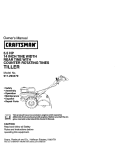
Caution:
Read and follow
all Safety Rules
and Instructtons
Before Operating
Th,s Equ,pment
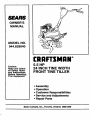
5.5 HP
24 INCH TINE WIDTH
FRONT TINE TILLER
• Assembly
• Operation
• Customer Responsibilities
• Service and Adjustments
• Repair Parts
Sears Canada, Inc., Toronto, Ontario M5B 2B8
Safe
Operation
SAFETY
RULES Powered
for Walk-Behind
Practices
TRAINING
•
•
Read the Owner's Manual carefully. Be thoroughly
familiar with the controls and the proper use of the
equipment. Know how to stop the unit and disengage
the controls quickly.
Never allow children to operate the equipment. Never
allow adults to operate the equipment without proper
instruction.
Keep the area of operation clear of all persons, particularly small children, and pets.
•
•
•
•
•
•
•
•
•
PREPARATION
•
Thoroughly inspect the area where the equipment is to
be used and remove all foreign objects.
•
Disengage all clutches _,nd shift into neutral before
starting the engine (motor).
•
Do not operate the equipment without weadng, adequate outer garments. Wear footwear that wm improve footing on slippery surfaces.
• " Handle fuel with care; ifi s highly flammable.
•
Use an approved fuel container.
•
Never add fue_to a running engine or hot engine.
Fill fuel tank outdoors with extreme care. Never fillfuel
"=_..tank-indeers;-
•
.........
•
•
•
•
Replace gasoline cap securely and clean up spilled
Tu-eTSbf6_'erestarting.
Use extension cords and receptacles as specified by
the manufacturer for all units with electric dik,e motors
or electric starting motors.
Never attempt to make any adjustments while the
engine (motor) is running (except where specifically
recommended by manufacturer).
•
Tillers
Never operate the tiller without proper guards, plates,
or other safety protective devices in place.
Keep children and pats away.
Do not overload the machine capacity by attempting to
till too deep at too fast a rate.
Never operate the machine at high speeds on slippery
surfaces. Look behind and use care when backing.
Never allow bystanders near the unit.
Use only attachments and accessodes approved by
the manufacturer of the tiller.
Never operate the tiller without good visibility or light.
Be careful when tilling in hard ground. The tines may
catch in the ground and propel the tiller forward. If this
occurs, let go of the handlebars and do not restrain the
machine.
MAINTENANCE
•
Rotary
AND
STORAGE
Keep machine, attachments, and accessories in safe
working condition.
Check shear pins, engine mounting bolts, and other
bolts at frequent intervals for proper tightness to be
sure the equipment is in safe working condition.
Never store the machine with fuel in the fuel tank inside
a building where ignition sources are present, such as
hot water and space heaters, clothes dryers, snd the
like. Allow the engine to cool before stodng in any
enclosure.
Always refer to the operator's guide instructions for
important details if the tiller is to be stored for an
extended period.
- IMPORTANT
-
CAUTIONS, IMPORTANTS,
AND NOTES ARE A MEANS
OF ATTRACTING
ATTENTION
TO IMPORTANT
OR
CRITICAL INFORMATION
IN THIS MANUAL.
OPERATION
•
Do not put hands or feet near or under rotaUng parts.
•
Exercise extreme caution when operating on or crossing gravel drives, walks, or roads. Stay alert for hidden
hazards or traffic. Do not carry passengers.
•
After stdklng a foreign object, stop the engine (motor),
remove the wire from the spark plug, thoroughly inspect the tiller for any damage, and repair the damage
before restarting and operating the tiller.
•
Exercise caution to avoid slipping or falling.
•
If the unit should start to vibrate abnormally, stop the
engine (motor) and check immediately for the cause.
Vibration is generally a warning of trouble.
•
Stop the engine (motor) when leaving the operating
position.
•
Take all possible precautions when leaving the mechine unattended. Disengage the tines, shift into
neutral, and stop the engine.
•
Before cleaning, repaidng, or inspecting, shut off the
engine and make certain all moving partshave stopped.
Disconnect the spark plug wire, and keep the wire
away from the plug to prevent accidental starting.
Disconnect the cordon electdc motors.
•
Do not run the engine indoors; exhaust fumes are
dangerous.
IMPORTANT:
POSSIBILITY
USED TO ALERT YOU THAT THERE
OF DAMAGING THIS EQUIPMENT.
IS A
NOTE: Gives essential information that will aid you to
petter understand, incorporate, or execute a particular set
of instructions.
[&
&
2
Look for this symbol to point out important safety precautions.
It means
CAUTIONIII BECOME ALERT!It YOUR
SAFETY IS INVOLVED.
CAUTION: Always disconnect spark
plug wire and place wire where it cannot contact spark plug in order to prevent accidental starting when setting
up, transporting, adjusting or making
repairs.
iI
I
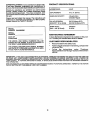
PRODUCT
CONGRATULATIONS
onyourpurchase
ofa SearsTiller.
It hasbeendesigned,engineered
andmanufactured
to
giveyouthebestpossibledependability
andperformance.
Should you experience any problems you cannot easily
remedy, please contact your nearest authorized Sears
Service Centre/Department. They have competent, welltrained technicians and the proper toolsto service or repair
this unit.
HORSEPOWER:
5.5 HP
DISPLACEMENT:
13 cu. in. (221cc)
GASOLINE CAPACITY:
4 Quarts (2,8L)
UnleadedRegular
OIL (API-SF/SG/SH):
CAPACITY:20 oz. I0.6L])
SAE 30 (Above32°1=)
SAE 5W-30 (Below32°1=)
SPARK PLUG :
GAP: .030" [0.76mm])
Champion
RJ19LM
Please read and retain this manual. The instructions will
enable you to assemble and maintain your tiller properly.
Always observe the "SAFETY RULES".
MODEL
NUMBER
SPECIFICATIONS
944.629540
SERIAL
NUMBER
MAINTENANCE
DATE OF
PURCHASE
A Sears Maintenance Agreement is available on this product. Contact your nearest Sears store for details.
THE MODEL AND SERIAL NUMBERS WILL BE
FOUND ON THE MODEL PLATE ATTACHED TO
THE RIGHT HAND ENGINE BRACKET.
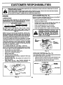
CUSTOMER RESPONSIBILITIES
YOU SHOULD RECORD BOTH SERIAL NUMBER
AND DATE OF PURCHASE AND KEEP IN A SAFE
PLACE FOR FUTURE REFERENCE.
AGREEMENT
•
Read and observe the safety rules.
•
Followa regular schedule in maintaining, cadng for and
using your tiller.
Follow
the instructions
under
"Customer
Responsibilities"and =Storage" sections ofthis Owner's
Manual.
•
IMPORTANT:
THIS UNIT IS EQUIPPED WITH AN INTERNAL COMBUSTION
ENGINE AND SHOULD NOT BE USED ON
OR NEAR ANY UNIMPROVED
FOREST-COVERED,
BRUSH-COVERED
OR GRASS COVERED
LAND UNLESS THE
ENGINE'S
EXHAUST SYSTEM IS EQUIPPED WITH A SPARK ARRESTER MEETING APPLICABLE LOCAL OR STATE
LAWS (IF ANY). IF A SPARK ARRESTER IS USED, IT SHOULD BE MAINTAINED IN EFFECTIVE WORKING ORDER BY
THE OPERATOR.
SEE YOUR SEARS AUTHORIZED
SERVICE CENTRE/DEPARTMENT
PARTS SECTION OF THIS MANUAL FOR PART NUMBER.
r3
FOR SPARK ARRESTER.
REFER TO THE REPAIR
TABLE OF CONTENTS
SERVICE & ADJUSTMENTS .................. ............... 14-17
STORAGE ......................................... .......................... 18
TROUBLESHOOTING .................................................
19
REPAIR PARTS-TILLER .......... .............................. 20-25
REPAIR PARTS-ENGINE ...................................... 26.30
SERVICE/PARTS ORDERING .................... Back Cover
SAFETY RULES ...........................................................
2
CUSTOMER RESPONSIBILITIES ..................... 3, 12-14
PRODUCT SPECIRCATIONS
.............................. _....... 3
WARRANTY ..................................................................
5
ASSEMBLY ................................................................
6-7
OPERATION .............................................................
8-11
MAINTENANCE SCHEDULE ...................................... 12
4
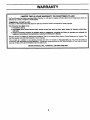
WARRANTY
LIMITED TWO (2) YEAR WARRANTY ON CRAFTSMAN TILLER
ForTwo (2) yearsfrom date of purchaseSearsCanada, Inc,willrepairor replaceat Searsoptionfree of chargepartswhichare
defectiveas a resultofmatedalor workmanship.
COMMERCIAL OR RENTAL USE:
Warrantyon Tillerwillbe thirty(30) daysfromdate ofpurchaseifusedfor commercialor rental purposes.
This Warranty does NOT coven
1. Pra-dellvery set-up.
2. Expandable Items which become worn dudng normal use, such as tines, spark plugs, air cleaners, shear pins,
and belts.
3, Repairs necessary because of operator abuse or negligence, Including the failure to oparate and maintain the
equipment according to the Instractlons contained in the Owner's Manual,
Warrantyserviceis availableby returningthe CraftsmanTillerto the nearestSears ServiceCentre/Departmentin Canada. This
warrantyappliesonlywhilethisproductis in use in Canada.
This warranty is in additionto any statutory warrantyand does not excludeor limitlegal dghtsyou may have but shall run
concurrentlywithapplicableprovinciallegislation.Furthermore,someprovincesdo NOT allowlimitationon how long an implied
warrantywilllastso the above limitationsmay notapplyto you.
SEARS CANADA, INC., TORONTO, ONTARIO M5B 2B8
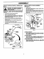
ASSEMBLY
Your new tiller has been assembled at the factory with exception of those parts left unassembled for shipping purposes. To
ensureosafe and proper operation of your tiller all parts and hardware you assemble must be tightened securely. Use the
correct tools as necessary to insure proper tightness.
TOOLS REQUIRED FOR ASSEMBLY
OPERATOR'S POSITION (See Fig. 1)
A socket wrench set will make assembly easier. Standard
wrench sizes are listed,
When right or left hand is mentioned in this manual, it
means when you are in the operating position (standing
behind tiller handles).
(1) Utility knife "
(1) Screwdriver
FRONT
(1) Pair of pliers
(2) 1/2" wrenches
LEFT
RIGHT
OPERATOR'S
POSITION
FIG. 1
CONTENTS
OF HARDWARE
PACK
(1) Plastic Cable Clip
(1) Manual
©
(2) Flange Locknuts 5116-18 UNC
(2) Carriage Bolts 5/16-18 UNC x 2-3/8 Gr. 5
©
(2) Hex Bolts 5/16-18 x 1-1/4
(1) Bottle Engine Oil
(2) Hex Nuts 5/16-18
6
(2) Lock Washers 5/16
ASSEMBLY
(See
ASSEMBLY
•
Loosen nut "A".
I _
I _U_
CAUTION:
Be careful of exposed
staples when handling or disposing of
i
|
•
Insert stake support between engine bracket halves
with stake spdng down.
cartoning material.
I
•
IMPORTANT:
WHEN UNPACKING AND ASSEMBLING
TILLER, BE CAREFUL NOT TO STRETCH OR KINK
Bolt stake support to engine brackets with bolts, lock
washers and nuts. Tighten securely. Tighten nut "A'.
•
Depth stake must move freely. If it does not, loosen
support bolt.
_
HANDLE
STAKE
CARTON
I_]
& INSTALL
INSTALL DEPTH
(See Fig. 3)
UNPACK
Fig. 2)
CABLE(S).
•
•
Cut cable ties secudng handle column.
Remove all packing from carton.
Secure handle column to handle mount using two (2)
carriage bolts and two (2) flange Iocknuts. Tighten both
flange Iocknuts securely.
•
Remove packing material from handle assembly.
•
Route fine control cable through plastic cable clip on
handle column.
•
Insert plastic cable clip into hole in handle column.
•
Cut cable ties securing tiller to skid.
•
Cut away carton and remove tiller from skid by pulling
backwards.
DEPTH STAKE
DEPTH
STAKE
I
I
TINE CONTROL.
SUPPORT
BOLT
HEX BOLTS,
LOCK WASHERS,
AND HEX NUTS
MOUNT _
TINECONTROL\
CABLE\ _
_
/ J
FIG. 3
f
/ _ "_
I
I
_HANDLE
HANDLE
•
HEIGHT
Handle height may be adjusted to better suit operator.
(See "HANDLE HEIGHT" in the Service and Adjustments section of this manual).
TILLING
WIDTH
•
Tilling width may be adjusted to better handle your
tilling conditions (See WINE ARRANGEMENT" in the
Service and Adjustments section of this manual).
TINE OPERATION
•
CARRIAGE"
\
/
YY_
_
_
/
/
/
CUP
]
FIG. 2
7
Check tine operation before first use. (See =TINE
OPERATION CHECK" in the Service and Adjustments
section of this manual).
OPERATION
KNOW YOUR TILLER
READ THIS OWNER'S MANUAL AND SAFETY RULES BEFORE OPERATING YOUR TILLER.
Compare the illustrations with your tiller to familiarize yourself with the location of various controls and adjustments. Save
this manual for future reference.
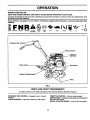
These symbols
meaning.
may appear on your Tiller or in literature supplied with the product. Learn and understand their
RUN I
OR WARNING
FORWARD
ON
OFF
11NE CONTROL
CHOKECONTROL
THROTTLE
DEPTI
RECOIL STARTER HANDLE
O
FIG. 4
MEETS ANSI SAFETY REQUIREMENTS
Our tillers conform to the safety standards of the American National Standards Institute,
FORWARD TINE CONTROL - Engages tines in forward
direction.
THROTTLE CONTROL - Controls engine speed.
DEPTH STAKE - Controls forward speed and the depth at
which the tiller will dig.
RECOIL STARTER HANDLE - Used to start the engine,
CHOKE CONTROL - Used when starting a cold engine.
8
OPERATION
The operation of any tiller can result in foreign objects thrown into the eyes, which can
result in severe eye damage. Always wear safety glasses or eye shields before starting
your tiller and while tilling. We recommend a wide vision safety mask over spectacles or
standard safety glasses.
HOW TO USE YOUR TILLER
TILLING
Know how to operate all controls before adding fuel and oil
or attempting to start engine.
The speed and depth of tilling is regulated by the position
of the depth stake and wheel height.
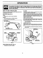
STOPPING (See Fig. 5)
The depth stake should always be below the wheels for
digging. It serves as a brake to slow the tiller's forward
motion to enable the tines to penetrate the ground. Also,
the more the depth stake is lowered into the ground the
deeper the tines will dig.
TINES
•
Release tine control to stop movement.
ENGINE
•
DEPTH STAKE (See Fig. 6)
Move throttle control to =STOP" position.
Adjust depth stake by removing the hairpin clip and clevis
pin. Change depth stake to desired position. Replace the
clevis pin and hairpin clip.
Never use choke to stop engine.
TINE CONTROL
"OFF" (UP) POSITION
•
For normaltilling, set depth stake at the second orthird
hole from the top.
WHEELS (See Fig. 6)
Adjust wheels by removing the hairpin clip and clevis pin.
Change wheel position. Replace the hairpin clip and clevis
pin.
•
For normal tilling,setwheels at the second orthird hole
from the top.
HAIRPIN CUP
AND CLEVIS PIN
\
CHOKE
DEPTH
STAKE
,THROTTLE
HAIRPIN CLIP
AND CLEVIS PIN
WHEEL
FIG. 5
FIG. 6
TINE
•
OPERATION
(See
Fig. 5)
Squeeze tine control to handle.
9
OPERATION
TO TRANSPORT
]_
ing, allow tiller engine and muffler to
cool. Disconnect spark plug wire. Drain
AUTION:from
Before
lifting or transportgasoline
fuel tank.
I
AROUND THE YARD
•
Tip depth stake forward until it is held by the stake
spring.
•
Push tiller handles down, raising tines off the ground.
•
Push or pull tiller to desired location.
AROUND TOWN
•
Disconnect spark plug wire.
•
Drain fuel tank.
•
Transport in upright position to prevent oil leakage.
WARNING: Experience indicates that alcohol blended
fuels (called gasohol or using ethanol or methanol) can
attract moisture which leads to separation and formation of
acids during storage. Acidic gas can damage the fuel
system of an engine while in storage. To avoid engine
problems, the fuel system should be emptied before
storage of 30 days or longer. Drain the gas tank, startthe
engine and let it run until the fuel lines and carburetor are
empty. Use fresh fuel next season. See Storage section
of this manual for additional information. Never useengine
or carburetor cleaner products inthe fuel tank or permanent
damage may occur.
CAUTION: Fill to within 1/2 inch of top
of fuel tank to prevent spiels and to
allow for fuel expansion. If gasoline ts
accidentally spilled, move machine
away from area of spill. Avoid creating
any source of ignition until gasoline
vapors have disappeared.
BEFORE STARTING ENGINE
IMPORTANT: BE VERY CAREFUL NOT TO ALLOW DIRT
TO ENTER THE ENGINE WHEN CHECKING OR ADDING
OIL OR FUEL. USE CLEAN OIL AND FUEL AND STORE
IN APPROVED, CLEAN, COVERED CONTAINERS. USE
CLEAN FILL FUNNELS.
TO START ENGINE
FILL ENGINE WITH OIL (SeeFig. 7)
•
Remove hangtag from engine.
•
With engine level, remove engine oil filler plug.
•
Fill engine with oilto point of overflowing. For approximate capacity see =PRODUCT SPECIFICATIONS" on
page 3 of this manual.
Tilt tiller back on its wheels and then re-level.
•
Do not overfill. Wipe off any spiEled oil
or fuel. Do not store, spill or use gasoline near an open flame.
•
With engine level, refill to point of overflowing ifnecessary. Replace oil filler plug.
•
For cold weather operation you should change oil for
easier starting (See =OIL VISCOSITY CHART" in the
Customer Responsibilities section of this manual).
•
To change engine oil, see the Customer Responsibilities section of this manual.
I
_
(See Fig. 8)
position
starting
engine.in "OFF"
CAUTION:when
Keep
tine control
I
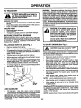
When starting engine for the first time or if engine has run
out of fuel, itwilltake extra pulls ofthe recoil starter to move
fuel from the tank to the engine.
•
Make sure spark plug wire is properly connected.
•
•
Place throttle control in "FAST" position.
Move choke control to full "CHOKE" position. Grasp
recoil starter handle with one hand and grasp tiller
handle with other hand. Pull rope out slowly until
engine reaches start of compression cycle (rope will
pull slightly harder at this point).
Pull recoil starter handle quickly. Do not let starter
handle snap back against starter. Repeat if necessary.
•
•
If engine fires but does not start, move choke control to
half choke position. Pull recoil starter handle until
engine starts.
•
When engine starts, slowly move choke control to
=RUN" position as engine warms up.
NOTE: A warm engine requires less choking to start.
OIL
FILLER
PLUG
FIG. 7
ADD GASOLINE
•
•
Move throttle control to desired running position.
•
Allow engine to warm up for a few minutes before
engaging tines.
NOTE: If at a high altitude (3000 feet) or in cold temperatures (below 32°F), the carburetor fuel mixture may need to
be adjusted for best engine performance. See "TO ADJUST CARBURETOR" in the Service and Adjustments
section of this manual.
Fill fuel tank. Use fresh, clean, regular unleaded
gasoline. (Use of leaded gasoline will increase carbon
NOTE: If engine does not start, see troubleshooting
and lead oxide deposits and reduce valve life.)
IMPORTANT: WHEN OPERATING IN TEMPERATURES
BELOW 32°F (0°C), USE FRESH, CLEAN, WINTER GRADE
GASOLINE TO HELP INSURE GOOD COLD WEATHER
STARTING.
10_ "
points.
OPERATION
_
You will find tilling much easier if you leave a row
untilled between passes. Then go back between tilled
rows. (See Fig. 9) There are two masons for doing this.
First, wide turns are much easier to negotiate than
about-faces. Second, the tiller won't be pulling itself,
and you, toward the row next to it.
PARK
PLUG
CHOKE
CONTROL
THROTTLE
ECO,
Set depth stake and wheel height for shallow tilling
when working extremely hard soil or sod. Then work
across the first cuts at normal depth.
co_
I
FIG. 8
BREAKING IN YOUR TILLER
Break-in your belt(s), pulleys and tine control before you
actually begin tilling.
•
Start engine, tip tines off ground by pressing handles
down and engage tine control to start tine rotation.
Allow tines to rotate for five minutes.
•
Check tine operation and adjust if necessary. See
WINE OPERATION CHECK" in the Service and Adjustments section of this manual.
FIG. 9
CULTIVATING
Cultivating is destroying the weeds between rows to prevent them from robbing nourishment and moisture from
the plants. At the same time, breaking up the upper layer
of soil crust will help retain moisture in the soil. Best
digging depth is 1" to 3".
TILLING HINTS
I&
handling your tiller, start actual field
use
AUTION:
with throttle
Untilyouereaceustomedto
in slow position.
I
• You will probably not need to use the depth stake.
Begin by tipping the depth stake forward until it is held
by the stake spring.
To help tiller move forward, liftup the handles slightly(thus
lifting depth stake out of ground). To slow down the tiller,
press down on handles.
• Cultivate up and down the rows at a speed which will
allow tines to uproot weeds and leave the ground in
rough condition, promoting no further growth of weeds
andgrass (See Fig. 10).
if you are straining or tiller is shaking, the wheels and depth
stake are not set propedy in the soil being tilled. The proper
setting of the wheels and depth stake is through tdal and
error and depends upon the soil condition. (The harder or
wetter the ground, the slower the engine and tlne speed
needed. Under these poorconditions, et fast speedthetiller
will run and jump over the ground).
i
A propedy adjusted tiller will dig with little effort from the
operator.
•
•
Tilling is digging into, turning over, and breaking up
packed soil before planting. Loose unpacked soil
helps root growth. Best tilling depth is 4" to 6". A tiller
will also clear the soil of unwanted vegetation. The
decomposition of this vegetable matter endches the
soil. Depending on the climate (rainfall and wind), it
may be advisable to tillthe soilat the end of the growing
season to further condition the soil.
A
Soil conditions are important for pmpor tilling.Tines will
not readily benetmte dry, hard soil which may contdbute to excessive bounce and difficult handling of your
tiller. Hard soil should be moistened before tilling;
however, extremely wet soil will "bail-up" or clump
during tilling. Wait until the soil is less wet in order to
achieve the best results. When tillingin the fall, remove
vines and long grass to prevent them from wrapping
around the tine shaft and slowing your tillingoperation.
FIG. 10
il
CUSTOMER
RESPONSIBILITIES
SCHEDULE
FILL IN DATES
AS YOU COMPLETE
REGULAR SERVICE
Check Engine Oil Level
SERVICE DATES
V' !
Change Engine Oil
<2
Oil PivotPoints
ll/
v'
Inspect Spark Arrestsr / Muffler
Inspect Air Screen
l/
Clean or Replace Air Cleaner Cadddge
Clean Engine Cylinder Rns
v'
Replace Spark Plug
v'
1- Changemoreoftenwh(moperatingundera heaw loadorIn highambienttemperatures.
2 - Senatemoreoftenwhenoperating
In dirtyordustyconditions.
GENERAL RECOMMENDATIONS
LUBRICATION
CHART
The warranty on this tiller does not cover items that have
been subjected to operator abuse or negligence. To
receive full value from the warranty, operator must maintain tiller as instructed in this manual.
Some adjustments will need to be made periodically to
properly maintain your tiller.
** ENGINE
All adjustments in the Service and Adjustments section of
this manual should be checked at least once each
season.
•
Once a year you should replace the spark plug, clean
or replace air filter, and check tines and belt for wear.
A new spark plug and clean air filter assure proper airfuel mixture andhelp your engine run better and last
longer.
BEFORE
EACH
USE
•
Check engine oil level.
•
•
Check tine operation.
Check for loose fasteners.
* IDLER
ARM
LUBRICATION
* SAE 30 OR 5W30 MOTOR OIL
** REFER TO CUSTOMER RESPONSIBILITIES"ENGINE " SEC'nON.
Keep unitwell lubricated(See"LUBRICATION CHAR'r").
12
CUSTOMER
RESPONSIBILITIES
|
Disconnect spark plug wire before performing any maintenance (except carburetor adjustment) to prevent
accidental
starting of engine.
Prevent flree! Keep the engine free of grass, leaves, spilled o11,or fuel. Remove fuel from tank before Upping
unit for maintenance. Clean muffler area of ell grass, dirt, and debris.
Do not touch hot muffler or cylinder fins as contact may cause bums.
I
L
ENGINE
AIR CLEANER (See Fig. 13)
LUBRICATION
Service air cleaner cartridge every 50 hours, more often if
engine is used in very dusty conditions,
•
Loosen air cleaner screws, one on each side of cover.
Use only high quality detergent oil rated with API service
classification SF, SG or SH. Select the oil's SAE viscosity
grade according to your expected temperature.
SAE VIscOSITY
GRADES
-20'
-20°
-10"
0°
TEMPERATIJRE RANGE ANTICIPATED
•
Remove air cleaner cover.
•
Carefully remove air cleaner cartridge. Be careful. Do
not allow dirt or debris to fall into carburetor.
•
Clean by tapping gently on a flat surface.
•
•
If vePJ dirty or damaged, replace cartridge.
Clean and replace cover. Tighten screws securely.
10_
20°
30"
BEFORE NEXT OIL CHANGE
&
FIG. 11
NOTE: Althoughmulti-viscosity oils (5W-30, 10W-30, etc.)
improve starting in cold weather, these multi-viscosityoils
will rasult in increased oil consumption when used above
32°F (0°C). Check your engine oil level more frequently to
avoid possible engine damage from running low on oil.
CAUTION: Petroleum solvents, such
as kerosene, are not to be used to clean
cartridge. They may cause deterloratlon of the cartridge.
Do not oll cartridge. Do not use pressurized air to
clean or dry cartridge.
Change the oil after every 50 hours of operation or at least
once a year if the tiller is not used for 50 hours in one year.
Check the crankcase oil level before starting the engine
and after each five (5) hours of continuous use. Add SAE
30 motor oil or equivalent. Tighten oil filler plug securely
each time you check the oil level.
TO CHANGE ENGINE OIL (See Figs. 11 and 12)
Determine temperature range expected before oilchange.
All oil must meet API service classification SF, SG or SH.
•
•
•
•
•
•
•
•
Be sure tiller is on level surface.
Oil will drain more freely when warm.
Catch oil in a suitable container.
Remove drain plug.
Tip tiller forward to drain oil.
After oil has drained completely, replace oil drain plug
and tighten securely.
Remove oil filler plug. Be careful not to allow dirt to
enter the engine.
Refill engine with oil. See "CHECK ENGINE OIL
LEVEL" In the Operation section of this manual.
FIG. 13
COOLING
SYSTEM
(See
Fig. 14)
'
Your engine is air cooled. For proper engine performance
and long life keep your engine clean.
•
Clean air screen frequently using a stiff-bdsUedbrush.
•
Remove blower housing and clean as necessary.
•
Keep cylinder fins free of dirt and chaff.
OIL
DRAIN
PLUG
/dR SCREEN
CYUNDER FINS
OIL RLLER
PLUG
FIG. 12
FIG. 14
13
1
I
CUSTOMER
RESPONSIBILITIES
MUFFLER
TRANSMISStON
Do not _perate tiller without muffler. Do not tamper with
exhaust system. Damaged mufflers or spark arresters
could create a fire hazard. Inspect pedodically and replace
if necessary. If your engine Is equipped with a spark
arrester screen assembly, remove every 50 hours for
cleaning and inspection. Replace if damaged.
Yourtransmissionissealedandwillonlyrequirelubrication
ifit is serviced.
CLEANING
•
Clean engine, wheels, finish, etc. of all foreign matter.
•
Keep finished surfaces and wheels free of all gasoline,
oil, etc.
•
Protect painted surfaces with automotive type wax.
SPARK PLUG
Replace spark plugs at the beginning of each tilling season
orafter every 50 hours of use, whichevercomesfirst. Spark
plug type and gap setting is shown in =PRODUCT SPECIFICATIONS" on page 3 of this manual.
We do not recommend using a garden hose to clean your
unit unless the muffler, air filter and carburetor are covered
to keep water out. Water in engine can result in a shortened
engine life.
SERVICE AND ADJUSTMENTS
I
contact with plug.
CAUTION: Disconnect spark plug wire from spark plug end place wire where It cannot come into
I&
I
I
TILLER
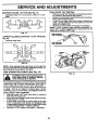
TINE ARRANGEMENT
TO ADJUST HANDLE HEIGHT (See Fig. 15)
Your outer tines can be assembled in several different ways
to suit your tilling or cultivating needs.
iA----.o--, i
Factory assembly has provided lowest handle height. Se•lect handle height best suited for your tilling conditions.
Handle height will be different when tiller digs into soil.
•
Ifa hi_her handle height is desired, loosen the four nuts
securing handle panel to engine brackets.
•
Slide handle panel to desired location.
•
Tighten the four nuts securely.
gloves or other protection when hen
dling tines.
NORMAL TILLING - 24" PATH (See Fig. 16)
•
Assemble holes "A" in tine hubs to holes "B" in tine
shaft.
ENGINE
BRACKETS
HANDLE
PANEL
NUTS (ALSO 2
ON LEFT SIDE
OF TILLER)
HAIRPIN CLIP
INNER TINE
FIG. 16
FIG. 15
14
SERVICE AND ADJUSTMENTS
FINAL CHECK "ON" POSITION
•
With tine control =ON"(held down to handle) push down
on handle to raise tines off the ground.
•
Slowly pull recoil starter handle while observing tines.
Tines should rotate forward,
•
If tines do not rotate, inner wire of control cable is too
loose. Loosen cable clip and pull cable up to remove
slack and retighten clip.
•
Recheck in "ON" position and adjust if necessary.
NOTE: If "ON" position check required adjustment, recheck =OFF" position adjustment to insure tines do not
rotate when control is =OFF" (up).
MID-WIDTH TILLING - 22" PATH (See Fig. 17)
•
Assemble holes =A" in tine hubs to holes "C" in Une
shaft.
C
FIG. 17
NARROW TILLING/CULTIVATING
Fig. 18)
•
Remove outer tines.
TINE CONTROL
- 12-3/4" PATH (See
IIO
J-t_..._
Ioo
O
O
CABLE
CUP
_
CONTROL
CABLE "
/
('i
INNER TINES ONLY
FIG. 18
NOTE: When reassembling outer tines, be sure right Une
assembly (marked =R") and left tine assembly (marked =L")
are mounted to correct side of tine shaft.
TINE OPERATION
I&
CHECK
\
(See Fig. 19)
from spark plug to prevent starting
while
ARNING:
checking
Disconnectsparkplugwlre
Une operation.
FIG. 19
I
For propertine operation, Une control lever must be against
control body and all slack removed from inner wire of
control cable when control is in the "OFF" (up) position.
If lever and cable are loose, loosen cable clip at lower end
of cable. Pull up on cable to remove slack, without
extending spring on end of cable, and retighten cable clip.
FINAL CHECK "OFF" POSITION
•
With tine control "OFF" (up), push down on handle to
raise tines off the ground.
•
Slowly puUrecoil starter handle while observing tines.
Tines should not rotate.
•
If tines rotate, Inner wire of control cable is too tight
which is extending lower spring and engaging tines.
Loosen cable clipand push down on cable only enough
to relieve spring tension. Tighten cable clip.
•
Recheck in =OFF" position and adjust if necessary.
15
SERVICE AND ADJUSTMENTS
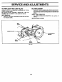
TO REPLACE
V-BELT
(See
BELT REPLACEMENT
Fig. 20)
•
Replace V-belt If it has stretched considerably or if it has
cracks or frayed edges,
Belt guard must be removed to service belt. See =TO
REMOVE BELT GUARD" in this section of manual.
CHECK TINE OPERATION
BELT REMOVAL
•
Install newV-belt to engine pulleyfirst then totransmission pulley. Be sure belt Is positioned on Inside groove
of both pulleys, inside all belt guides and rests on Idler
pulley.
•
Remove V-belt from transmission pulley first and then
from engine pulley,
See =TINE OPERATION
manual,
CHECK" in this section of
REPLACE BELT GUARD
BELT
GUIDE
/
ENGINE PULLEY
PULLEY
\
\
BELT
GUIDE
IDLER
PULLEY
FIG. 20
16
V-BELT
SERVICE AND ADJUSTMENTS
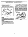
TO REMOVE
BELT
GUARD
(See
Fig. 21)
•
Remove screws from sides of belt guard.
•
Pull belt guard out and away from unit.
•
Replace belt guard by reversing above procedure. Be
sure slot in bottom of belt guard is under head of tine
shield bolt and all nuts are tightened securely.
BELT GUARD
SCREW
SCREW
IDLE RPM ADJUSTMENT
•
TO adjust idle RPM, rotate throttle linkage counterclockwise and hold against stop while adjusting idle
speed adjusting screwto obtain 1750 RPM. Release
throttle linkage.
High speed stop is factory adjusted. Do not adjust or
damage may result,
IMPORTANT:
NEVER TAMPER WITH THE E_IGINE
GOVERNOR, WHICH IS FACTORY SET FOR PROPER
ENGINE SPEED. OVERSPEEDING THE ENGINE ABOVE
THE FACTORY HIGH SPEED SETTING
CAN BE
DANGEROUS. IF YOU THINK THE ENGINE-GOVERNED
HIGH SPEED NEEDS ADJUSTING, CONTACT YOUR
NEAREST
AUTHORIZED
SERVICE
CENTER/
DEPARTMENT, WHICH HAS THE PROPER EQUIPMENT
AND EXPERIENCE
TO MAKE ANY NECESSARY
ADJUSTMENTS.
THROTTLE LINKAGE
\
THROTTLE STOP
TINE
SHIELD
'_
SCREW
FIG. 21
ENGINE
Maintenance, repair, or replacement of the emission control devices and systems, which are being done at the
customers expense, may be performed by any non-road
engine repair establishment or individual. Warranty repairs
must be performed byan authorized engine manufacturer's
service outlet.
TO ADJUST
CARBURETOR
(See
IDLE SPEED
ADJUS_NG SCREW
IDLE NEEDLE VALVE
FIG. 22
Fig. 22)
The carburetor has s high speed fixed jet and has been
preset at the factory and adjustment should not be necessary. However, minor adjustments may be required to
compensate for differences in fuel, temperature, altitude or
load. If the carburetor does need adjustment, proceed as
follows.
17
STORAGE
ENGINE
Immediately prepare your tiller for storage at the end of the
season or if the unit will not be used for 30 days or more.
OIL
Drain oil (with engine warm) and replace with clean oil.
(See "ENGINE" in the Customer Responsibilities section of
this manual).
CAUTION: Never store the tiller with
gasoline In the tank inside a building
where fumes may reach an open flame
or spark. Allow the engine to cool
before storing In any enclosure.
CYLINDER(S)
TILLER
•
Remove sparkplug.
•
Pour 1 ounce (29 ml) of oil through spark plug hole into
cylinder.
•
Pull starter handle slowly several times to distribute oil.
Clean entire tiller (See =CLEANING" in the Customer
Responsibilities section of this manual).
•
Replace with new spark plug.
Inspect and replace belts, if necessary (See belt replacement instructions in the Service and Adjustments
section of this manual).
OTHER
•
Do not store gasoline from one season to another.
Lubricate as shown in the Customer Responsibilities
section of this manual.
•
Replace your gasoline can if your can starts to rust.
Rust and/or dirt in your gasoline will cause problems.
•
Be sure that all nuts, bolts and screws are securely
fastened. Inspect moving partsfordamage, breakage
and wear. Replace if necessary.
•
If possible, store your unit indoors and cover itto give
protection from dust and dirt.
•
Touch up all rusted or chipped paint surfaces; sand
lightly before painting.
•
Cover your unit with a suitable protective cover that
does not retain moisture. Do not use plastic. Plastic
cannot breathe which allows condensation to form and
will cause your unit to rust.
IMPORTANT:
NEVER COVER TILLER WHILE ENGINE
AND EXHAUST AREAS ARE STILL WARM.
ENGINE
FUEL SYSTEM
IMPORTANT:
IT IS IMPORTANT
TO PREVENT
GUM
DEPOSITS
FROM
FORMING
IN ESSENTIAL
FUEL
SYSTEM
PARTS SUCH AS THE CARBURETOR,
FUEL
FILTER, FUEL HOSE, OR TANK DURING STORAGE.
ALSO,
EXPERIENCE
INDICATES
THAT ALCOHOL
BLENDED
FUELS
(CALLED
GASOHOL
OR USING
ETHANOL OR METHANOL)
CAN ATTRACT MOISTURE
WHICH LEADS TO SEPARATION
AND FORMATION OF
ACIDS DURING STORAGE. ACIDIC GAS CAN DAMAGE
THE FUEL SYSTEM OF AN ENGINE WHILE IN STORAGE.
•
Drain the fuel tank.
•
Start the engine and let it run until the fuel lines and
carburetor are empty.
Never use engine or carburetor cleaner products in the
fuel tank or permanent damage may occur.
Use fresh fuel next season.
,
•
NOTE: Fuel stabilizer is an acceptable alternative in
minimizing the formation of fuel gum deposits during storage. Add stabilizer to gasoline in fuel tank or storage
container. Always follow the mix ratio found on stabilizer
container. Run engine at least 10 minutes after adding
stabiUzerto allow the stabUizerto reach the carburetor. Do
not drain the gas tank and carburetor if using fuel stabilizer.
18
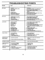
TROUBLESHOOTING
PROBLEM
POINTS
CAUSE
CORRECTION
1.
2.
3.
4.
5.
Out of fuel.
Engineriot"CHOKED"proparly.
Engineflooded.
Dirtyair cleaner.
Water in fuel.
1.
2.
3.
4.
5.
6.
7.
8.
9.
Cloggedfuel tank.
Loosesparkplug wire.
Bad sparkplugor impropargap.
Carburetorout of edjustmant.
6.
7.
8.
9.
Fillfueltank.
See "TO START ENGINE"In the Operationsection.
Wait several minutesbeforeattemptingto start.
Clean or replaceair cleaner certddge.
Drainfuel tankand carburetor,and refilltankwith fresh
gasoline.
Removefuel tankand clean.
Make sure sparkplugwire isseated propsdyon plug.
Replacesparkplugor adjustgap.
Make necessaryadjustments.
Hard to start
1. Throttle control not set pmpedy.
2. Dirty air cleaner.
3. Bad spark plug or lmpmpar gap.
4, Stale or dirty fuel.
5. Loose spark plug wire.
6. Carburetor out of adjustment.
1.
2.
3.
4.
5.
6.
Placethrottle controlin "FAST"position.
Clean or replacesir cleaner cartddge.
Replacesparkplugor adjustgap.
Drainfuel tank and refillwithfresh gasoline.
Make sure sparkplugwire is seated pmpedyon plug.
Make necessaryadjustments.
Loss of power
1.
2.
3.
4.
5.
Engine is ovedcaded.
Dirty air clsensr.
Low oil levai/dirty oil
Faulty spark plug.
Oil in fuel.
6.
7.
Stale or dirty fuel.
Water in fuel.
1.
2.
3.
4.
5.
6.
7.
Set depthstakeend wheelsfur shallowertilling.
Clsen or replace air cleanercartddgs.
Check oillevel/changeoil.
Clsen and regapor change spark plug.
Drainand cleanfuel tank and refill,andclean carburetor.
Drainfuel tank and refillwith freshgasoline.
Drainfueltank andcarburetor,and refilltank withfresh
gasoline.
Removefuel tank andclean.
Connectand tightensparkplug wire.
Clean angine air screan.
Clsen/replecemuffler.
Make necseseryedjustmanta.
Contactan authodzed servicecanter/department.
Will not start
8.
9.
10.
11.
12.
13.
Engine overheats
1.
2.
3.
4.
5.
Excessive bounce/
difficult handling
8.
9.
10.
11.
12.
13.
Cloggedfuel tank.
Sparkplugwire loose.
Dirtyengineair ssreen.
Dirty/ologgedmuffler.
Carburetorout of adjustment.
Poorcompression.
Low oillevel/dirtyoil.
Dirtyengineair screen.
Dirtyengine.
Partioltypluggedmuffler.
Impropercarburetor edjustment.
I.
2.
3.
4.
5.
Check oil level/change oil.
Clean engine air screen.
Clean cylinder fins, air screen, muffler area.
Remove end clean muffler.
Adjust carburetor to richer position.
1. Groundtoodry andherd.
1.
Moistan ground or wait for more favorable soil
conditions.
2. Wheels anddepth stakeincorrectlyadjusted.
2.
Adjust wheels and depth stake.
Soil bells up or clumps
1. Groundtoo wet.
1.
Wait for more favorable soil conditions.
Engine runs but ttller
won't move
1. Tlne controlis notengaged.
2. V-beltnotcorrectlyadjusted.
3. V-baitis offpulley(s).
1. Engage tinecontrol.
2. Inspect/edjustV-bait.
3. InspectV-bait.
Engine rune but labom
when tilling
1, Tillingtoodeep.
2. Throttlecontrolnot propedyadjusted.
3. Carburetoroutof adjustment.
1.
2.
3,
19
Set depth stake for shallower tilling.
Check throttle control setting.
Make necessary adjustments,
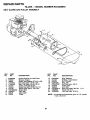
REPAIR PARTS
TILLER
HANDLE
- - MODEL NUMBER 944.629540
ASSEMBLY
5
4
4
11
12
KEY
NO.
1
2
3
4
5
6
7
8
PART
NO.
72010520
137118
152094
9266R
3066J
151229
12000027
154805
DESCRIPTION
Bolt 5/16-18 x 2-1/2
Panel, Control
Assembly, Handle Column
Grip, Handle
Cable, Tine Control
Lever, Control, Tine
Ring, Clip
Pin, Pivot
KEY
NO.
PART
NO.
9
10
11
12
13
14
73970500
165197
110514X
98000129
STD533107
12000059
NOTE:
20
DESCRIPTION
Locknut, Flange 5/16-18 UNC
Clip, Cable
Assembly, Panel and Tube
Nut, Flan_e
Bolt, Carnage 5/16-18 x 3/4
Retainer, Ring
All component dimensions given in U.S. inches.
1 inch = 25.4 mm
REPAIR PARTS
TILLER
- - MODEL NUMBER
944.629540
BELT GUARD AND PULLEY ASSEMBLY
KEY
NO,
1
2
3
4
5
6
7
8
9
10
11
12
PART
NO.
23230596
130812
166361
74610812
17490440
165770
165503
139155
155768X558
109227X
9484R
9180R
DESCRIPTION
Screw Set 5/16-18 x 3/8 Patch
Sheave, Engine
Screw, HexWasher STL#10 x 3/8
Bolt, Hex Head 1/2-20 x 3/4
Bolt, Thd Roller 1/4-20 x 2-1/2
shield, Inner Belt Guard
Screw Hex Wsh Hd #8-18 x 1/2
Spacer Split .523 x .718 x 2.0
Guard, Belt
Pad, Idler
Clip, Cable
V-Belt
KEY
NO.
PART
NO.
13
14
15
16
17
18
19
20
21
25
12000028
151223
165504
12000036
STD541237
161806
162290
STD523712
106968X
73350500
NOTE:
21
DESCRIPTION
Ring, Retainer
Sheave, Transmisison
Nut J Clip #8
Ring, Klip
Nut, Hex, Jam 3/8-16
Pulley, Idler
Arm, Idler
Bolt, Hex Head 3/8-16 x 1-1/4
Shaft, Idler Arm
Nut, Hex, Jam 5/16-18
All component dimensions given in U.S. inches.
1 inch = 25.4 mm
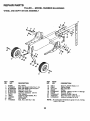
REPAIR PARTS
TILLER - - MODEL NUMBER
WHEEL
AND DEPTH
STAKE
944.629540
ASSEMBLY
7
6
2
3
2
22
4
7
5
4
2O
18
17
KEY
NO.
PART
NO.
1
2
3
4
5
6
7
6
9
10
11
9194R
74760520
STD523107
STD541031
STD551131
STD541437
4921H
1952J
122233X
326J
74780628
DESCRIPTION
Pin, Clevis
Bolt, Hex Head 5/16-18 x 1-1/4
Bolt, Hex Head 5/16-18 x 314
Nut, Hex 5/16-18
Washer, Lock 5/16
Locknut, w/washer 3/8-16
Clip, Hairpin
Support,Depth Stake, R.H.
Stake, Depth
Pin, Clevis
Bolt, Hex 3/8-16 x 1-3/4
KEY
NO.
PART
NO.
13
15
16
17
18
19
20
21
22
1951J
5388J
121117X
9188R
STD551037
9190R
STD541437
74760516
STD541431
NOTE:
22
DESCRIPTION
Support, Depth Stake, L.H.
Spring, Stake
Bolt, Shoulder
Wheel
Washer 13/32 x 13/16 x 11 Gauge
Bracket, Wheel
Locknut, Crown 3/8-16
Bolt, Hex Head 5116-18 x 1
Locknut, w/insert 5/16-18
All component dimensions given in U.S. inches.
1 inch = 25.4 mm
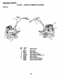
REPAIR PARTS
TILLER - - MODEL NUMBER
944.629540
TINE ASSEMBLY
2
2
6
/
6
6
I
5
6
KEY
NO.
1
2
3
PART
NO,
156926
163552
156924
KEY
NO.
DESCRIPTION
4
5
6
Tine. Outer, R.H.
Retianer, Spring Z nc
Tine, lnner, R.H.
23
PART
NO.
156923
156925
4929H
DESCRIPTION
Tine, Inner, L.H.
Tine, Outer, L.H.
Pin, Clevis
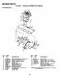
REPAIR PARTS
TILLER - - MODEL NUMBER 944.629540
TRANSMISSION
1
_j
3
3
14
14
/_,
15
KEY
NO.
PART
NO.
1
2
3
5
6
7
8
9
10
11
12
13
74760524
STD523732
STD551037
STD541437
9056R558
165835
165834
STD551131
STD541031
74760544
151222
9173R
10
14
DESCRIPTION
Bolt, Hex 5/16-18 x 1-112 Grade 2
Bolt, Fin, Hex 3/8-16 x 3-1/4
Washer 13/32 x 13/16 x 11
Locknut, w,_vasher 3/8-16
Shield, Tine
Bracket, Engine, R.H.
Bracket, Engine, L.H.
Washer, Lock 5/16
Nut, Hex 5/16-18
Bolt, Hex Head 5/16-18 x 2-3/4
Transmission
Spacer, Split
KEY
NO.
PART
NO.
14
15
16
17
18
19
20
9173R
STD541431
19091412
19092016
STD551125
74610412
.....
DESCRIPTION
Spacer, Split
Nut, Hex, Keps 5/16-18 UNC
Washer 9/32 x 7/8 x 12 Gauge
Washer 9/32 x 1-114 x 16 Gauge
Washer, Lock 1/4
Bolt, Hex 1/4-28 x 3/4 Grade 5
Engine (See Breakdown)
Bdggs Model 137202-1124-E1 '
NOTE: All component dimensions given in U.S. inches.
1 inch = 25.4 mm
24
REPAIR PARTS
TILLER - - MODEL NUMBER
944.629540
DECALS
6
KEY
NO.
1
2
4
5
6
8
9
10
11
---
PART
NO.
166217
166214
166215
137283
110614X
120076X
165279
165268
162384
168361
168362
DESCRIPTION
Decal, Logo
Decal Logo .
Decal 5Hp/24
Decal Cntrl Phi Inst.
Decal Hand Placement
Decal Warning, Rotating Tines
Decal 5.5 HP
Decal Craftsman
Decal Tine Shield Warning
Manual, Owner's (English)
Manual, Owner's (French)
25
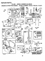
REPAIR PARTS
TILLER - - MODEL NUMBER
BRIGGS & STRATFON
944.629540
ENGINE - - MODEL NUMBER
137202, TYPE NO. 1124-E1
.870
* 869
307
13
i1
+3
3 7_5 308
3O6
741
10
529
15
528
26
25OO
614
4,5
219
v
26
-,_
,!'°'_-_
_
I_
_
"_'=----_:"
_'_1
.,...
l-
TO INSTALL SEE REPAIR
INSTRUCTION MANUAL.
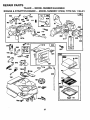
REPAIR PARTS
TILLER - - MODEL NUMBER
BRIGGS & STRATTON
944.629540
ENGINE - - MODEL NUMBER
27
137202, TYPE NO. 1124-E1
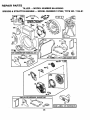
REPAIR PARTS
TILLER - - MODEL NUMBER 944.629540
BRIGGS & STRATTON ENGINE - - MODEL NUMBER 137202, TYPE NO. 1124-E1
334
"A"REQUIRES SPECIAL TOOLS
TO INSTALL SEE REPAIR
INSTRUCTION MANUAL
23
73
2OO
37
307
689_
58
66
66
I19
'095VA OV
1036 LABEL
28
KIT-EMISSION
I
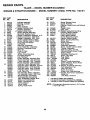
REPAIR PARTS
TILLER
BRIGGS & STRAI-rON
KEY PART
NO. NO.
1
2
3
5
7
8
9
10
11
12
13
14
15
16
18
19
20
21
21A
22
23
24
25
26
27
28
29
30
32
33
34
35
497144
399268
299819
214040
272157
495774
27549
94621
66578
270080
270125
270126
94221
94679
94918
492088
94388
494044
495660
294606
281658
899195
94980
393673
222898
298904
298905
298906
298907
298982
299742
298983
298984
298985
26026
298909
298908
299430
390459
221890
94745
211119
261044
260552
- - MODEL NUMBER
944.629540
ENGINE - - MODEL NUMBER
KEY PART
NO. NO.
DESCRIPTION
Cylinder Assembly
Bushing, Cylinder
* Seal, Oil
. Head, Cylinder
o Gasket, Cylinder Head
Breather Assembly
e* Gasket, Valve Cover
Screw, Breather Mounting
Grommet, Breather Tube
* Gasket, Crankcase, Standard .015"
* Gasket, Crankcase .005" Thick
* Gasket, Crankcase .009" Thick
Screw, Cylinder Head 2-3/32"
Screw, Cylinder Head 2-15/32"
Plug, Pipe, Hex Socket
Crankshaft
Gear Key, Crankshaft
Cover Assembly, Crankcase
Bushing, Crankcase Cover
* Seal, Oil
Plug, Oil Filler
Cap, Oil Fill
Screw, Cover Mounting
Flywheel, Magneto
Key, Flywheel
Piston Assembly, Standard Size
Piston Assembly .010" Oversize
Piston Assembly .020"Oversize
Piston Assembly .030"Oversize
Ring Set, Piston, Standard Size
Ring Set, Piston, Standard, Chrome
Ring Set, Piston .010" Oversize
Ring Set, Piston .020" Oversize
Ring Set, Piston .030" Oversize
Lock, Piston Pin
Pin Assembly, Piston, Standard
Pin Assembly, Piston .005" Over
Rod Assembly, Connecting
Rod Assembly, Connecting
.020" Undersize Crankpin Bore
Dipper, Connecting Rod
Screw, Connecting Rod
Valve, Exhaust
Valve, Intake
Spring, Intake Valve
36
37
40
26478
222443
93312
45
46
51
55
56
58
260642
214726
273113
497442
498144
66894
60 691915
65 94904
65A 94669
73 225176
81 222263
90 498298
95 93499
96 223793
97 497600
108 497230
111 262715
121 495606
124 94913
127 220352
127A 223789
147 231955
152 260575
154 93527
162 490589
163 271935
180 495405
181 494559
190 94924
190A 94919
191 272489
200 223886
202 262280
*
•
o
137202, TYPE NO. 1124-E1
DESCRIPTION
Spring, Exhaust Valve
Guard, Flywheel
Retainer, Intake Valve and Exhaust
Spring
Tappet, Valve
Gear, Cam
e,* Gasket, Carburetor Mounting
Housing, Rewind Starter
Pulley, Rewind Starter
Rope, Rewind Starter
HCUtto Required Length)
andle, Rewind Starter
Screw, Housing Mounting
Screw, Hex
Screen, Rotating
Lock, Screw
Carburetor Assembly
Screw, Throttle Valve to Shaft
Throttle, Carburetor
Shaft and Lever, Throttle
Valve and Shaft Group, Choke
Spring, Choke
Carburetor Overhaul Kit
Screw, Hex Head
Plug, Welch
Plug, Welch
Jet, Pilot
Spring, Throttle Adjustment
Screw, Machine, Round Head
Screw and Collar
0* Gasket, Air Cleaner Mounting
Tank Assembly, Fuel
Cap, Fuel Tank
Screw, Fuel Tank
Screw, Fuel Tank Mounting
•* Gasket, Fuel Tank to Carburetor
Guide, Air
Link, Mech. Governor
Included in Gasket Set (495603)
Included in Carburetor Overhaul Kit (495606)
Included in Valve Overhaul Gasket Set (498529)
NOTE: All component dimensions given in U.S. inches
1 inch = 25.4 mm
29
REPAIR PARTS
TILLER - - MODEL NUMBER 944.629540
BRIGGS & STRATTON ENGINE - - MODEL NUMBER 137202, TYPE NO. 1124-E1
KEY
NO.
PART
NO.
DESCRIPTION
203
205
208
209
211
212
216
219
220
222
227
230
256
257
300
304
305
306
307
308
332
333
334
337
346
356
358
363
373
383
392
393
394
414
432
433
434
435
455
456
459
467
524
526
527
528
529
535
536
280720
231520
262279.
262948
263031
262270
262359
494845
221551
490649
490374
94927
223813
93543
493936
495759
690960
224820
94680
224738
94877
397358
93414
802592
94896
398808
495603
19069
94908
89838
262328
225058
272538
220982
221377
93265
213963
93141
225121
281503
281505
280715
271485
94914
223786
231550
67838
491435
494279
Ball Crank
Screw, Shoulder
Rod, Speed Control
Spring, Governor
Spring, Governor Idle
Link, Throttle
Link, Choke
Gear, Governor
Washer, Thrust
Panel, Control
Lever Assembly, Governor
Washer, Governor Lever
Crank, Bell
Screw, Slotted Hex
Muffler, Exhaust
Housing, Blower
Screw, Blower Housing Mounting
Shield, Cylinder
Screw, Cylinder Shield
Cover, Cylinder Head
Nut, Flywheel
Armature Group
Screw, Armature Mounting.
Plug, Spark
Screw, Sems
Wire, Ground
Gasket Set
Flywheel Puller
Nut, Hex
Wrench, Spark Plug
Spring, Fuel PumpDiaphragm
Screen, Carburetor
° Diaphragm
Washer
Cap, Spring
Pin, Diaphragm Cover
Cover, Diaphragm
Screw, Diaphragm Cover
Cup, Starter
Retainer
Pawl, Starter
Knob, Control
Seal, O-Ring
Screw, Seres, Tank Bracket Mount.
Clamp, Breather Tube
Tube, Breather
Grommet, Breather Tube
Filter, Air
Cleaner, Air
KEY
NO.
PART
NO.
DESCRIPTION
Screw
94897
Bushing, Governor Crank
231079
Bolt, Governor Lever
94907
Nut, Hex
231978
Starter Assembly, Rewind
692696
Pipe, Fuel
231068
Fuel Pipe and Clip Assembly
391813
Screw, Hex Head, Shoulder
93935
Pin, Cotter
93306
Crank, Governor
495243
Switch, Stop
396847
Screw, Shoulder
94943
Washer, Throttle Shaft, Foam
271853
66538
Elbow, Spark Plug
Deflector, Exhaust, Side Outlet
393757
Washer, Foam
270382
Washer, Brass
221839
Spring, Friction
263073
Gear, Timing
262992
Link, Speed Control
262570
Anchor, Spring
225029
Cable Terminal, Ignition
493880
Seat, Intake Valve, Standard
211787
Seat, Exhaust Valve, Standard
211172
Guide, Exhaust Valve
262001
Guide, Intake Valve
63709
* Gasket, Exhaust
883 272309
Rack, Gear Control
916 280321
Base, Air Cleaner
966 492797
Filter, Air Cleaner
967 491588
Cover, Air Cleaner
968 495872
Screw, Air Cleaner
969 490073
Screw, Hex Head
971 94902
Seal, Throttle Shaft
987 398970
Lever, Bracket Assembly
995 225057
Retainer, Link
1012 490507
Label, Kit, Emissions
1036 499345
Gasket Set, Valve Overhaul
1095 498529
2500 137202-1114 Replacement Engine
-- -- 491145
Replacement Shortblock
542
552
562
592
608
611
612
613
614
616
621
623
634
635
676
679
680
689
741
779
780
851
869
870
871
RPM Settings:
*
•
e
Low Speed: 1750-1950
High Speed: 3400-3600
Included in Gasket Set (495603)
Included in Carburetor Overhaul Kit (495606)
Included in Valve Overhaul Gasket Set (498529)
NOTE: All component dimensions given in U.S.
inches 1 inch = 25.4 mm
3O
SERVICE NOTES
31
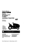
[RIIFTXMRN°
SEA $
5.5 HP
24 INCH TINE WIDTH
FRONT TINE TILLER
OWNER'S
MANUAL
Each tiller has its own model number. Each engine has its own model
number.
The model number for your tiller will be found on a plate attached to the
right hand engine bracket.
MODEL NO.
944.629540
The mode[ number for your engine will be found on the blower housing of
the engine.
All parts listed herein may be ordered from any Sears Canada, Inc.
Service Centre and most Retail Stores.
WHEN ORDERING REPAIR PARTS, ALWAYS GIVE THE FOLLOWING INFORMATION:
•
PRODUCT - FRONT TINE TILLER
•
HOW TO ORDER
REPAIR PARTS
'
" MODEL NUMBER - 944.629540
•
ENGINE MODEL NUMBER - 137202, TYPE NUMBER 1124-E1
•
PART NUMBER
•
PART DESCRIPTION
Your Sears merchandise has added value when you consider Sears has
sewice units nationwide staffed with Sears trained technicians,., professional technicians specifically trained to insure that we meet our pledge
to you, we service what we sell.
NEED A PART?
SEARS HAS ACCESS TO OVER 800,000 PARTS
WHETHER IT'S A SPARK PLUG OR LAWN MOWER BLADE.
SEARS PARTS AND SERVICE CAN SUPPLY YOU WITH
TOP QUALITY REPAIR PARTS FOR ALL YOUR PRODUCTS.
JUST CALL ONE OF THE FOLLOWING NUMBERS TO PLACE YOUR
ORDER. IF CALLING LOCALLY:
Regina - 566-5124
Montreal - 333-5740
Toronto - 744-4900
Halifax - 454-2444
Kitchener - 894-7590
Ottawa - 738-4440
Vancouver - 420-8211
ALL OTHER AREAS CALL 1-800-665-4455
Sears Canada, Inc., Toronto, Ontario M5B 2B8
168361
1.04.99 TR
PRINTED IN THE U.S,A.