1
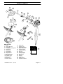
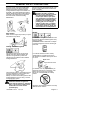
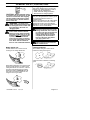
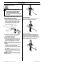
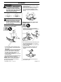
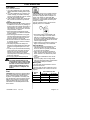
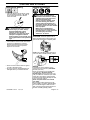
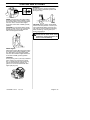
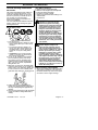
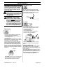
Operator’s manual
Manuel d’utilisation
Manual de instrucciones
B28 PS
Please read the operator’s manual carefully and make sure you understand the instructions
before using the machine.
Lire attentivement et bien assimiler le manual d’utilisation avant d’utiliser la machine.
Lea detenidament el manual de instrucciones y asegúrese de entender su contenido antes
de utilizar la máquina.
GB (2 - 27)
FR (28 - 53)
ES (54 - 79)
SYMBOL EXPLANATION
Symbols
This product is in accordance
with applicable EC directives.
WARNING: Careless or incorrect
use of clearing saws, brushcutters,
and trimmers can result in serious
or fatal injury to the operator or
others.
Please read the operator’s manual
carefully and make sure you
understand the instructions
before using the machine.
Always wear:
S A protective helmet where there
is a risk of falling objects
S Hearing protection
S Approved eye protection
Max. speed of output shaft, rpm
Noise emission to the
environment according to the
European Community’s
Directive. The machine’s
emission is specified in the
Technical data section and
on label.
Sound pressure level at
7,5 metres.
Use unleaded petrol and
two--stroke oil mixed at a
ratio of 2% (1:50).
Beware of thrown objects and
ricochets.
The operator of the machine
shall ensure, while working,
that no persons or animals
come closer than 15 metres.
BLADE THRUST -- Machines fitted
with grass blades can be thrown
violently to the side or rear when
the blade comes into contact with
a fixed object. The blade is
capable of amputating an arm
or leg. Always keep people and
animals at least 15 metres from
the machine.
Other symbols/decals on the machine
refer to special certification requirements
for certain markets.
Stop the engine by pushing
and holding the stop switch
in the STOP position. CAUTION!
The stop switch automatically
returns to the start position.
In order to prevent unintentional
starting, the spark plug cap must be
removed from the spark plug when
assembling, checking and/or
performing maintenance.
Regular cleaning is required.
Never use saw toothed blades
with this machine.
Visual check.
Arrows which show limits for
handle mounting.
Approved eye protection must
always be used.
Always wear approved protective
gloves.
Choke
Use anti--slip and stable boots.
Primer bulb
115432326 Rev. 4
2/17/12
English--- 2
CONTENTS
Contents
KEY TO SYMBOLS
Symbols . . . . . . . . . . . . . . . . . . . . . . . . . 2
CONTENTS
Contents . . . . . . . . . . . . . . . . . . . . . . . . 3
Note the following before starting . . . . 3
WHAT IS WHAT?
What is what? . . . . . . . . . . . . . . . . . . . 4
GENERAL SAFETY PRECAUTIONS
Important . . . . . . . . . . . . . . . . . . . . . . . . 5
Personal protective equipment . . . . . . 5
Machine’s safety equipment . . . . . . . . 6
Cutting equipment . . . . . . . . . . . . . . . . . 8
ASSEMBLY
Fitting the loop handle . . . . . . . . . . . . . 10
Assembling and dismantling the
two-piece shaft . . . . . . . . . . . . . . . . . . . 10
Fitting the harness and harness clamp 11
Fitting blades . . . . . . . . . . . . . . . . . . . . . 12
Fitting a blade guard, grass blade and
grass cutter . . . . . . . . . . . . . . . . . . . . . . 12
Fitting the trimmer guard and
trimmer head . . . . . . . . . . . . . . . . . . . . . 12
FUEL HANDLING
Fuel safety . . . . . . . . . . . . . . . . . . . . . . . 13
Fuel . . . . . . . . . . . . . . . . . . . . . . . . . . . . 13
Fuelling . . . . . . . . . . . . . . . . . . . . . . . . . 14
STARTING AND STOPPING
Check before starting . . . . . . . . . . . . . . 15
Starting and stopping . . . . . . . . . . . . . . 15
WORKING TECHNIQUES
General working instructions . . . . . . . . 17
MAINTENANCE
Carburetor . . . . . . . . . . . . . . . . . . . . . . . 20
Muffler . . . . . . . . . . . . . . . . . . . . . . . . . . 20
Spark plug . . . . . . . . . . . . . . . . . . . . . . . 21
Two-piece shaft . . . . . . . . . . . . . . . . . . . 21
Air filter . . . . . . . . . . . . . . . . . . . . . . . . . . 21
Bevel gear . . . . . . . . . . . . . . . . . . . . . . . 22
Maintenance schedule . . . . . . . . . . . . . 23
TECHNICAL DATA
Technical data . . . . . . . . . . . . . . . . . . . . 24
EC--declaration of conformity
(Applies to Europe only) . . . . . . . . . . . . 25
115432326 Rev. 4
2/17/12
Note the following before
starting:
Please read the operator’s manual carefully.
WARNING: Under no circumstances may the design of the
machine be modified without the
permission of the manufacturer.
Always use genuine accessories.
Non-- authorized modifications
and/or accessories can result
in serious personal injury or the
death of the operator or others.
WARNING: A clearing saw,
brushcutter or trimmer can be
dangerous if used incorrectly or
carelessly, and can cause serious
or fatal injury to the operator or
others. It is extremely important
that you read and understand the
contents of this operator’s manual.
WARNING: Long-- term exposure
to noise can result in permanent
hearing impairment. So always use
approved hearing protection.
McCulloch has a policy of continuous
product development and therefore
reserves the right to modify the design and
appearance of products without prior
notice.
English--- 3
WHAT IS WHAT?
2
3
6
1
29
5
7
11
4
9
12
10
19
13
20
28
21
18
8
1
17
15
23
22
16
14
22
25
4
27
4
26
24
What is what?
1.
2.
3.
4.
5.
6.
7.
8.
9.
10.
11.
12.
13.
14.
15.
Blade
Grease filler cap
Bevel gear
Cutting attachment guard
Upper shaft
Lower shaft
Loop handle
Throttle control
Stop switch
Throttle lock--out
Harness clamp
Cylinder cover
Starter handle
Fuel tank
Choke control
115432326 Rev. 4
2/17/12
16.
17.
18.
19.
20.
21.
22.
23.
24.
25.
26.
27.
28.
29.
30.
Primer bulb
Air filter cover
Handle adjustment
Blade retainer nut
Cupped washer
Retaining washer
Dust cup
Trimmer head
Transport guard
Hex wrench
Wrench
Harness
J--handle
Shaft coupling
Operator’s manual
30
English--- 4
GENERAL SAFETY PRECAUTIONS
Important
IMPORTANT! The machine is only designed
for trimming grass, grass clearing and/or
forestry clearing.
The only accessories you can operate with
this engine unit are the cutting attachments we
recommend in the section on Technical data.
Never use the machine if you are tired, if you
have drunk alcohol, or if you are taking medication that could affect your vision, your judgement or your co--ordination.
Never use the machine in extreme weather
conditions such as severe cold, very hot and/
or humid climates.
Wear personal protective equipment. See instructions under the heading Personal protective equipment.
Never use a machine that has been modified
in any way from its original specification.
Never use a machine that is faulty. Carry out
the checks, maintenance and service instructions described in this manual. Some maintenance and service measures must be carried
out by trained and qualified specialists. See
instructions under the heading Maintenance.
All covers and guards must be fitted before
starting. Make sure the spark plug cap and
lead are not damaged. Otherwise you could
get an electric shock.
The machine operator must ensure that no
people or animals come closer than 15 metres
while working. When several operators are
working in the same area, the safety distance
should be at least 15 metres.
WARNING: This machine produces an electromagnetic field
during operation. Under some circumstances, this field may interfere
with active or passive medical
implants. To reduce the risk of
serious or fatal injury, we recommend persons with medical
implants to consult their physician
and the medical implant manufacturer before operating this machine.
WARNING: Using an incorrect
cutting attachment or an incorrectly
filed blade can increase the risk of
serious or fatal injury.
WARNING: Never allow children
to use or be in the vicinity of the
machine. As the machine is equipped
with a spring--loaded stop switch and
can be started by low speed and
force on the starter handle, even
small children under some circumstances can produce the force necessary to start the machine. This can
mean a risk of serious personal injury. Therefore remove the spark plug
cap when the machine is not under
close supervision.
Personal protective equipment
WARNING: A clearing saw,
brushcutter or trimmer, if used incorrectly or carelessly, can cause
serious or fatal injury to the operator
or others. It is extremely important
that you read and understand the
contents of this operator’s manual.
You must use approved personal
protective equipment whenever you
use the machine. Personal protective equipment cannot eliminate the
risk of injury but it will reduce the
degree of injury if an accident does
happen. Ask your dealer for help in
choosing the right equipment.
IMPORTANT! Listen for warning signals
or shouts when you are wearing hearing
protection. Always remove your hearing
protection as soon as the engine stops.
HELMET
A helmet should be worn if the brush being
cleared is taller than 2 metres.
HEARING PROTECTION
Wear hearing protection that provides
adequate noise reduction.
EYE PROTECTION
Always wear approved eye protection. If
you use a visor then you must also wear
approved protective goggles. Approved
protective goggles must comply with EN
166 in EU countries.
115432326 Rev. 4
2/17/12
English--- 5
GENERAL SAFETY PRECAUTIONS
GLOVES
Gloves should be worn when necessary,
e.g., when fitting cutting attachments.
BOOTS
Wear anti--slip and stable boots.
WARNING: Never use a machine
that has faulty safety equipment!
Follow the control, maintenance
and service instructions described
in this section. If your machine fails
any of these checks contact your
service agent to get it repaired. Use
of a machine with faulty safety equipment increases the risk of serious
personal injury or death of the
operator or others.
Throttle lock--out
CLOTHING
Wear clothes made of a strong fabric and
avoid loose clothing that can catch on
shrubs and branches. Always wear heavy,
long pants. Do not wear jewelry, shorts
sandals or go barefoot. Secure hair so it is
above shoulder level.
The throttle lock--out is designed to prevent
accidental operation of the throttle control.
When you press the lock--out (A) (i.e. when
you grasp the handle) it releases the
throttle control (B). When you release the
handle, the throttle control and the throttle
lock--out both move back to their original
positions. This movement is controlled by
two independent return springs. This arrangement means that the throttle control is
automatically locked at the idle setting.
A
FIRST AID KIT
A first aid kit should be carried by operators of clearing saws, brushcutters or trimmers.
B
Make sure the throttle control is locked at
the idle setting when the throttle lock--out is
released.
Machine’s safety equipment
This section describes the machine’s safety equipment, its purpose, and how checks
and maintenance should be carried out to
ensure that it operates correctly. See the
“What is what” section to locate where this
equipment is positioned on your machine.
The life span of the machine can be reduced and the risk of accidents can increase if machine maintenance is not carried out correctly and if service and/or repairs are not carried out professionally. If
you need further information please contact
your nearest service workshop.
IMPORTANT! All servicing and repair work
on the machine requires special training. This
is especially true of the machine’s safety
equipment. If your machine fails any of the
checks described below you must contact
your service agent. When you buy any of our
products we guarantee the availability of professional repairs and service. If the retailer
who sells your machine is not a servicing
dealer, ask him for the address of your nearest service agent.
115432326 Rev. 4
2/17/12
Press the throttle lock--out and make sure
it returns to its original position when you
release it.
Check that the throttle control and throttle
lock--out move freely and that the return
springs work properly.
English--- 6
GENERAL SAFETY PRECAUTIONS
See instructions under the heading Start.
Start the machine and apply full throttle.
Release the throttle and check that the
cutting attachment stops and remains at a
standstill. If the cutting attachment rotates
with the throttle in the idle position then the
carburettor idle setting must be checked.
See instructions under the heading
Maintenance.
Use of incorrectly wound trimmer line or an
incorrect cutting attachment increases the
level of vibration.
WARNING:
Overexposure to
vibration can lead to circulatory
damage or nerve damage in people
who have impaired circulation.
Contact your doctor if you experience symptoms of overexposure to
vibration. Such symptoms include
numbness, loss of feeling, tingling,
pricking, pain, loss of strength,
changes in skin color or condition.
These symptoms normally appear
in the fingers, hands or wrists. The
risk increases at low temperatures.
Muffler
Stop switch
Make sure the engine stops when you push
and hold the stop switch.
The muffler is designed to reduce the noise
level and to direct the exhaust gases away
from the operator.
CAUTION! Muffler is fitted with a catalytic
converter designed to reduce exhaust gas
emissions.
Cutting attachment guard
This guard is intended to prevent loose
objects from being thrown towards the
operator. The guard also protects the
operator from accidental contact with the
cutting attachment.
In countries that have a warm and dry
climate there is a significant risk of fire.
We therefore fit mufflers with a spark arrestor mesh.
Muffler bolts
Spark arrestor mesh
Check that the guard is undamaged and not
cracked. Replace the guard if it has been
exposed to impact or is cracked.
Always use the recommended guard for the
cutting attachment you are using. See the
“Technical data” section.
For mufflers, it is very important that you
follow the instructions on checking, maintaining, and servicing your machine.
Never use a machine that has a faulty
muffler.
WARNING:
Never use a cutting
attachment without an approved
guard. See the section on “Technical
data”. If an incorrect or faulty guard
is fitted this can cause serious
personal injury.
115432326 Rev. 4
2/17/12
Regularly check that the muffler is securely
attached to the machine.
English--- 7
GENERAL SAFETY PRECAUTIONS
Cutting equipment
CAUTION: Mufflers fitted with catalytic converters get very hot during use and
remain so for some time after stopping.
This also applies at idle speed. Contact
can result in burns to the skin. Remember the risk of fire!
WARNING:
The inside of the
muffler contains chemicals that may
be carcinogenic. Avoid contact with
these elements in the event of a
damaged muffler.
WARNING:
Engine exhaust
fumes contain carbon monoxide,
which can cause carbon monoxide
poisoning. DO NOT start or run the
machine indoors, or anywhere that
is poorly ventilated. The exhaust
fumes from the engine are hot and
may contain sparks which can start
a fire. Never start the machine indoors or near combustible material!
Blade retainer nut
A blade retainer nut is used to secure
some types of cutting attachment.
This section describes how to choose and
maintain your cutting equipment in order to:
S Reduce the risk of blade thrust.
S Obtain maximum cutting performance.
S Extend the life of cutting equipment.
IMPORTANT!
Only use cutting attachments with the guards
we recommend! See the section on
“Technical data”.
Refer to the instructions for the cutting attachment to check the correct way to load the
trimmer line and the correct line diameter.
Maintain the correct blade setting! Follow our
instructions and recommendations.
WARNING:
Always stop the engine before doing any work on the
cutting attachment. This continues
to rotate even after the throttle has
been released. Ensure that the
cutting attachment has stopped
completely and disconnect the
lead from the spark plug before
you start to work on it.
WARNING:
Using an incorrect
cutting attachment increases the
risk of blade thrust.
Cutting equipment
Grass blades and grass cutters are intended for cutting coarse grass.
A trimmer head is intended for trimming
grass.
When fitting, tighten the nut in the opposite
direction to the direction of rotation of the
cutting attachment. To remove it, undo the
nut in the same direction as the cutting
attachment rotates. CAUTION! The nut
has a left--hand thread. Tighten the nut
using the wrench (provided).
115432326 Rev. 4
2/17/12
English--- 8
GENERAL SAFETY PRECAUTIONS
General rules
Trimmer head
Only use cutting attachments with the
guards we recommend! See the section on
Technical data.
Check the cutting attachment for damage
or cracks. A damaged cutting attachment
should always be replaced.
WARNING:
Use of an incorrect
or damaged blade could result in
serious injury or death. Always
discard a blade that is bent,
twisted, cracked, broken or
damaged in any other way. Never
attempt to straighten a twisted
blade so that it can be reused. Only
use original blades of the specified
type.
115432326 Rev. 4
2/17/12
IMPORTANT!
Always ensure the trimmer line is wound
tightly and evenly around the drum, otherwise the machine will generate harmful
vibration.
S Only use the recommended cutting attachments. See the section on “Technical
data”.
S Smaller machines generally require small
trimmer heads and vice versa. This is because when clearing using trimmer line
the engine must throw out the trimmer
line radially from the trimmer head and
overcome the resistance of the grass
being cleared.
S The length of the trimmer line is also important. A longer trimmer line requires
greater engine power than a shorter
trimmer line of the same diameter.
S Make sure that the cutter on the trimmer
guard is intact. This is used to cut the
trimmer line to the correct length.
S To increase the life of the trimmer line it
can be soaked in water for a couple of
days. This will make the line tougher so
that it lasts longer.
English--- 9
ASSEMBLY
NOTE: Make sure unit is assembled
correctly as shown in this manual.
S Push the attachment into the coupling
until the locking/release button snaps
into the primary hole (C).
Fitting the loop handle
S Position the handle on the shaft. Note that
the handle must be mounted between the
two arrows on the shaft.
C
S Before using the unit, tighten the knob
securely.
S Fit the screw, securing plate and wing nut
as shown in the diagram.
WARNING: All attachments are
designed to be used in the primary
hole unless otherwise stated in the
applicable attachment instruction
manual. Using the wrong hole could
lead to serious injury or damage to
the unit.
Dismantling:
S Loosen the coupling by turning the knob.
S Make a final adjustment of the J--handle
to a comfortable working position.
Tighten the wing nut.
WARNING:
To avoid serious
injury, only use grass blades/grass
cutters or trimmer heads with plastic
blades when the J-handle is fitted.
Never use saw blades!
Assembling and dismantling
the two--piece shaft
A
S Press and hold the locking/release button
(A).
S While securely holding the engine and
upper shaft, pull the attachment straight
out of the coupling.
Assembly:
S Loosen the coupling by turning the knob.
S Position locking/release button (A) of
attachment into guide recess (B) of
coupling.
A
B
115432326 Rev. 4
2/17/12
English--- 10
ASSEMBLY
Fitting the harness
WARNING:
When using a
brushcutter, it must always be
hooked securely to the harness.
Otherwise, you will be unable to
control the brushcutter safely.
This can result in injury to yourself
or others.
Proper harness and handlebar adjustments must be made with the engine completely stopped before using unit.
Fitting the harness clamp
S Place the upper harness clamp over the
shaft and position the lower harness
clamp under the shaft. Align the upper
and lower clamp screw holes. Clamp
must be fitted above the arrow on the
shaft (see illustration).
Correct height
Adjust the harness so that the cutting attachment is parallel to the ground.
Correct balance
S Insert two screws into the screw holes.
S Secure harness clamp by tightening
screws with a hex wrench.
Adjusting the harness
S Insert your right arm and head through
the harness and allow it to rest on your
left shoulder. Make sure the harness
hook is to the right side of your waist.
NOTE: A one-half twist is built in the harness to allow the harness to rest flat on the
shoulder.
S Adjust the harness, allowing the hook to
be about 15 cm below the waist.
S Fasten the harness to the harness clamp
on the shaft and lift the unit to the operating position.
S Put on the harness. Now make a final
adjustment so that the unit is in a comfortable working position when it hangs
from the harness.
NOTE: It may be necessary to relocate
the harness clamp on the shaft for proper
balancing of unit.
115432326 Rev. 4
2/17/12
Let the cutting attachment rest lightly on
the ground. If you use a grass blade, it
should balance about 10 cm above the
ground to prevent contact with stones and
the like. Adjust the position of the harness
clamp to balance the unit correctly.
English--- 11
ASSEMBLY
Fitting blades
WARNING:
When fitting blades,
it is extremely important that the
raised section on the retaining washer engages correctly in the centre
hole of the blade. If the blade is fitted
incorrectly, it can result in serious
and/or fatal personal injury.
S Place the cupped washer (F) onto the
shaft with the cupped side of the washer
toward the blade.
S Install the blade retainer nut (G). Tighten
the nut using the wrench (provided).
Turn in the opposite direction to the direction of rotation (CAUTION! left-hand
thread).
WARNING:
Never use a cutting
attachment without an approved
guard. See the section on Technical data. If an incorrect or faulty
guard is fitted this can cause serious personal injury.
Fitting the trimmer guard and
trimmer head
Fitting a blade guard, grass
blade and grass cutter
S Hook the trimmer guard/combination
guard (A) onto the fitting on the shaft and
secure with the bolt (D).
G
F
E
D
D
C
B
C
B
A
A
A
S Hook the blade guard/combination guard
(A) onto the fitting on the shaft and secure
with the bolt.
CAUTION! Use the recommended blade
guard. See the Technical data section.
S Turn the shaft until one of the holes in
the dust cup (B) aligns with the corresponding hole in the gearbox.
S Insert a small screwdriver (C) in the hole
to lock the shaft.
S Place the blade (D) and retaining washer
(E) onto the shaft of the gearbox.
NOTE: Make sure the raised part of the
retaining washer is facing the gearbox
and the raised area fits into the hole in
the centre of the blade.
115432326 Rev. 4
2/17/12
S Turn the shaft until one of the holes in the
dust cup (B) aligns with the corresponding hole in the gearbox.
S Insert a small screwdriver (C) in the hole
to lock the shaft.
S Screw on the trimmer head (E) in the
opposite direction to the direction of
rotation.
E
S To dismantle, follow the instructions in
the reverse order.
English--- 12
FUEL HANDLING
Fuel safety
Petrol
Never start the machine:
1. If you have spilled fuel on it. Wipe off the
spillage and allow remaining fuel to evaporate.
2. If you have spilled fuel on yourself or your
clothes, change your clothes. Wash any
part of your body that has come in contact
with fuel. Use soap and water.
3. If the machine is leaking fuel. Check regularly for leaks from the fuel cap and fuel
lines.
Transport and storage
S Store and transport the machine and fuel
so that there is no risk of any leakage or
fumes coming into contact with sparks or
naked flames, for example, from electrical machinery, electric motors, electrical
relays/switches or boilers.
S When storing and transporting fuel always use approved containers intended
for this purpose.
S When storing the machine for long periods the fuel tank must be emptied. Contact your local petrol station to find out
where to dispose of excess fuel.
S Ensure the machine is cleaned and that
a complete service is carried out before
long--term storage.
S The transport guard must always be
fitted to the cutting attachment when the
machine is being transported or in storage.
S In order to prevent unintentional starting
of the engine, the spark plug cap must
always be removed during long--term
storage, if the machine is not under
close supervision and when performing
all service measures.
S Secure the machine during transport.
WARNING:
Fuel and fuel fumes
are highly inflammable and can
cause serious injury when inhaled
or allowed to come in contact with
the skin. For this reason observe
caution when handling fuel and
make sure there is adequate ventilation.
Fuel
CAUTION! The machine is equipped with a
two--stroke engine and must always be run
using a mixture of petrol and two-stroke
engine oil. It is important to accurately measure the amount of oil to be mixed to ensure
that the correct mixture is obtained. When
mixing small amounts of fuel, even small
inaccuracies can drastically affect the ratio
of the mixture.
115432326 Rev. 4
2/17/12
CAUTION! Always use a quality petrol/oil
mixture at least 90 octane (RON). If your
machine is equipped with a catalytic converter (see chapter on Technical data)
always use a good quality unleaded petrol/
oil mixture. Leaded petrol will destroy the
catalytic converter.
Use low--emission petrol, also known as
alkylate petrol, if it is available.
S The lowest octane recommended is 90.
If you run the engine on a lower octane
than 90, it can result in knocking. This
gives rise to a high engine temperature and
increased bearing load, which can result in
serious engine damage.
S When working at continuous high revs, a
higher octane rating is recommended.
Two--stroke oil
S For best results and performance, use
Universal Outdoor Accessories twostroke oil, which is specially formulated
for our two--stroke engines.
S Never use two--stroke oil intended for
water--cooled outboard engines, sometimes referred to as outboard oil (rated
TCW).
S Never use oil intended for four--stroke
engines.
S A poor oil quality and/or too high oil/fuel
ratio may jeapordise function and decrease
the lifetime of catalytic converters.
Mixing ratio
1:50 (2%) with Universal Outdoor Accessories two-stroke oil.
1:33 (3%) with oils class JASO FB or ISO
EGB formulated for air-cooled, two-stroke
engines.
Petrol,
litre
5
10
15
20
Two-- stroke oil, litre
2% (1:50)
0,10
0,20
0,30
0,40
3% (1:33)
0,15
0,30
0,45
0,60
English--- 13
FUEL HANDLING
Mixing
S Always mix the petrol and oil in a clean
container intended for fuel.
S Always start by flling half the amount of the
petrol to be used. Then add the entire
amount of oil. Mix (shake) the fuel mixture.
Add the remaining amount of petrol.
S Mix (shake) the fuel mixture thoroughly
before filling the machine’s fuel tank.
S Do not mix more than one month’s supply of fuel at a time.
S If the machine is not used for some time,
the fuel tank should be emptied and
cleaned.
WARNING:
The catalytic converter muffler gets very hot during
and after use. This also applies
during idling. Be aware of the fire
hazard, especially when working
near flammable substances and/or
vapors.
Fueling
WARNING:
Taking the following
precautions, will lessen the risk of
fire:
Do not smoke or place hot objects
near fuel.
Always shut off the engine before
refueling.
Always stop the engine and let
it cool for a few minutes before
refueling.
When refueling, open the fuel cap
slowly so that any excess pressure
is released gently.
Tighten the fuel cap carefully after
refueling.
Always move the machine away
from the refueling area before
starting.
S Clean the area around the fuel cap.
Contamination in the tank can cause
operating problems.
S Ensure that the fuel is well mixed by shaking the container before filling the tank.
Min. 3 m
115432326 Rev. 4
2/17/12
English--- 14
STARTING AND STOPPING
Check before starting
S Check the blade to ensure that no cracks
have formed at the bottom of the teeth or
by the centre hole. Discard a blade if
cracks are found.
WARNING:
Use of an incorrect
or damaged blade could result in
serious injury or death. Always
discard a blade that is bent,
twisted, cracked, broken or
damaged in any other way. Never
attempt to straighten a twisted
blade so that it can be reused. Only
use original blades of the specified
type.
Starting and stopping
WARNING:
The complete clutch,
clutch cover, and shaft must be
fitted before the machine is started,
otherwise parts could come loose
and cause personal injury.
Always move the machine away
from the refueling area before
starting. Place the machine on a
flat surface. Ensure the cutting attachment cannot come into contact
with any object.
Make sure no unauthorized
persons are in the working area,
otherwise there is a risk of serious
personal injury. The safety
distance is 15 meters.
Cold engine
Primer bulb: Press the primer bulb 10
times until fuel begins to fill the bulb. The
primer bulb need not be completely filled.
S Check that the trimmer head and trimmer
guard are not damaged or cracked.
Replace the trimmer head or trimmer
guard if they have been exposed to
impact or are cracked.
Choke: Move the blue engine choke lever
over to the FULL CHOKE (closed) position.
S Never use the machine without a guard
nor with a defective guard.
S All covers must be correctly fitted and undamaged before you start the machine.
115432326 Rev. 4
2/17/12
Starting
Hold the body of the machine on the
ground using your left hand (CAUTION!
Not with your foot!).
Firmly grip the starter rope handle with
your right hand. DO NOT squeeze
throttle trigger. Slowly pull out the cord
until you feel some resistance (the starter
pawls grip); then quickly and powerfully
pull the cord until engine attempts to start,
but no more than 3 times.
Never wrap the starter cord around
your hand.
Move the blue engine choke lever to the
HALF CHOKE (½) position. Repeat pulling
the cord until the engine starts and runs.
Then, move the blue engine choke lever to
the OFF CHOKE (opened) position.
English--- 15
STARTING AND STOPPING
Stopping
Stop the engine by pushing and holding
the stop switch in the STOP position until
the engine stops.
NOTE: If engine dies, return blue engine
choke lever to the HALF CHOKE (½) position and pull starter rope until engine starts
and runs. Then, move the blue engine
choke lever to the OFF CHOKE (opened)
position).
CAUTION! Do not pull the starter cord all
the way out and do not let go of the starter
handle when the cord is fully extended.
This can damage the machine.
CAUTION! The stop switch automatically
returns to the start position. In order to prevent unintentional starting, the spark plug
cap must be removed from the spark plug
when assembling, checking and/or performing maintenance.
WARNING: When the engine is
started with the choke in the closed
position the cutting attachment will
start to rotate immediately.
Warm engine
With a warm engine, Move the blue engine
choke lever to the HALF CHOKE (½) position. Pull starter rope until engine starts
and runs. Move the blue engine choke lever
to the OFF CHOKE (opened) position.
CAUTION!
Do not put any part of your body in marked
area. Contact can result in burns to the
skin, or electrical shock if the spark plug
cap has been damaged. Always use
gloves. Do not use a machine with damaged spark plug cap.
115432326 Rev. 4
2/17/12
English--- 16
WORKING TECHNIQUES
General working instructions
IMPORTANT!
This section describes the basic safety precautions for working with trimmers. If you
encounter a situation where you are uncertain how to proceed you should ask an expert. Contact your servicing dealer.
Avoid all usage which you consider to be
beyond your capability.
You must understand the difference between
forestry clearing, grass clearing and grass
trimming before use.
Basic safety rules
The ABC of clearing
Always use the correct equipment.
Make sure the equipment is well adjusted.
Follow the safety precautions.
Organise your work carefully.
Always use full throttle when starting to cut
with the blade.
S Avoid stones.
S
S
S
S
S
WARNING: Sometimes
branches or grass get caught
between the guard and cutting
attachment or wrapped around the
shaft. Neither the operator of the
machine nor anyone else may attempt to remove the cut material
while the engine is running or the
cutting equipment is rotating,
as this can result in serious injury.
Stop the engine and cutting equipment before you remove material.
The bevel gear can get hot during
use and may remain so for a while
afterwards. You could get burned if
you touch it.
1. Look around you:
S To ensure that people, animals or other
WARNING: Watch out for
things cannot affect your control of the
machine.
thrown objects. Always wear
S To ensure that people, animals, etc.,
approved eye protection. Never
do not come into contact with the cutlean over the cutting attachment
ting attachment or loose objects that
guard. Stones, rubbish, etc. can be
are thrown out by the cutting attachthrown up into the eyes causing
ment.
blindness or serious injury. Keep
S CAUTION! Do not use the machine
unauthorised persons at a disunless you are able to call for help in
tance. Children, animals, onlookers
the event of an accident.
and helpers should be kept outside
2. Do not use the machine in bad weather,
the safety zone of 15 m. Stop the
such as dense fog, heavy rain, strong
machine immediately if anyone
wind, intense cold, etc. Working in bad
approaches. Never swing the maweather is tiring and often brings added
chine around without first checking
risks, such as icy ground, unpredictable
behind you to make sure no one is
felling direction, etc.
within the safety zone.
3. Make sure you can move and stand safely.
Check the area around you for possible obstacles (roots, rocks, branches, ditches, etc.) Basic working techniques
S Always slow the engine to idle speed after
in case you have to move suddenly. Take
each working operation. Long periods at
great care when working on sloping ground.
full throttle without any load on the engine
can lead to serious engine damage.
4. Switch off the engine before moving to
another area. Fit the transport guard before
carrying or transporting the equipment any
distance.
5. Never put the machine down with the engine
running or while the cutting attachment is
rotating.
115432326 Rev. 4
2/17/12
English--- 17
WORKING TECHNIQUES
Grass clearing using a grass blade
Grass trimming with a trimmer head
Trimming
S Grass blades and grass cutters must not be
used on woody stems.
S A grass blade is used for all types of tall or
coarse grass.
S The grass is cut down with a sideways,
swinging movement, where the movement
from right--to--left is the clearing stroke and
the movement from left--to--right is the return
stroke. Let the left--hand side of the blade
(between 8 and 12 o’clock) do the cutting.
S If the blade is angled to the left when clearing grass, the grass will collect in a line,
which makes it easier to collect, e.g. by
raking.
S Try to work rhythmically. Stand firmly with
your feet apart. Move forward after the return stroke and stand firmly again.
S Reduce the risk of material wrapping
around the blade by following these instructions:
S Always work at full throttle.
S Avoid the previously cut material during
the return stroke.
S Stop the engine, unclip the harness and
place the machine on the ground before
you start to collect the cut
material.
S Hold the trimmer head just above the ground
at an angle. It is the end of the trimmer line
that does the work. Let the trimmer line work
at its own pace. Never press the trimmer
line into the area to be cut.
S The trimmer line can easily remove grass
and weeds up against walls, fences, trees
and borders, however it can also damage
sensitive bark on trees and bushes, and
damage fence posts.
S Reduce the risk of damaging plants by
shortening the trimmer line to 10--12 cm and
reducing the engine speed.
S When trimming you should use less than
full throttle so that the trimmer line lasts
longer and to reduce the wear on the
trimmer head.
Clearing
S The clearing technique removes all unwanted vegetation. Keep the trimmer
head just above the ground and tilt it. Let
the end of the trimmer line strike the
ground around trees, posts, statues and
the like. IMPORTANT! This technique
increases the wear on the trimmer line.
S The trimmer line wears quicker and must
be fed forward more often when working
against stones, brick, concrete, metal
fences, etc., than when coming into contact with trees and wooden fences.
115432326 Rev. 4
2/17/12
English--- 18
WORKING TECHNIQUES
Cutting
S The trimmer is ideal for cutting grass that
is difficult to reach using a normal lawn
mower. Keep the trimmer line parallel to
the ground when cutting. Avoid pressing
the trimmer head against the ground as
this can ruin the lawn and damage the
tool.
WARNING: Sometimes
branches or grass get caught
between the guard and cutting
attachment or wrapped around the
shaft. Neither the operator of the
machine nor anyone else may attempt to remove the cut material
while the engine is running or the
cutting equipment is rotating,
as this can result in serious injury.
Stop the engine and cutting equipment before you remove material.
The bevel gear can get hot during
use and may remain so for a while
afterwards. You could get burned if
you touch it.
WARNING: Watch out for thrown
S Do not allow the trimmer head to con-stantly come into contact with the ground
during normal cutting. Constant contact
of this type can cause damage and wear
to the trimmer head.
Sweeping
objects. Always wear eye protection.
Never lean over the cutting attachment guard. Stones, rubbish, etc.
can be thrown up into the eyes
causing blindness or serious injury.
Keep unauthorized persons at a distance. Children, animals, onlookers
and helpers should be kept outside
the safety zone of 15 m.
Stop the machine immediately if
anyone approaches.
S The fan effect of the rotating line can be
used for quick and easy clearing up.
Hold the trimmer line parallel to and
above the area to be swept and move
the tool to and fro.
S When cutting and sweeping you should
use full throttle to obtain the best results.
115432326 Rev. 4
2/17/12
English--- 19
MAINTENANCE
The owner is responsible for the performance of all required maintenance as
defined in the operator’s manual.
Idle Speed
Screw--T
Carburetor
Your McCulloch product has been designed
and manufactured to specifications that reduce harmful emissions. After the engine
has used 8--10 tanks of fuel, the engine
will be run--in. To ensure that it continues to
run at peak performance and to minimize
harmful exhaust emissions after the run--in
period, ask your servicing dealer to adjust
your carburetor.
WARNING:
The complete clutch,
clutch cover, and shaft must be
fitted before the machine is started,
otherwise parts could come loose
and cause personal injury.
WARNING:
If the idle speed cannot be adjusted so that the cutting
attachment stops, contact your servicing dealer. Do not use the machine until it has been correctly adjusted or repaired.
Unit/Maintenance Safety
Disconnect the spark plug before performing maintenance, except carburetor adjustments.
Muffler
Function
S The carburetor governs the engine’s
speed via the throttle control. Air and fuel
are mixed in the carburetor.
S The T--screw regulates the throttle setting
at idle speed. If the T--screw is turned
clockwise this gives a higher idle speed;
turning it counterclockwise gives a lower
idle speed.
Basic setting
S The basic carburetor settings are adjusted during testing at the factory. Fine
adjustment should be carried out by a
skilled technician.
CAUTION! If the cutting attachment rotates
when the engine is idling the idle adjustment
screw T should be turned counterclockwise
until the cutting attachment stops.
Recommended idle speed:
See “Technical data” section.
Recommended max. speed:
See “Technical data” section.
Fine adjustment of the idle speed--T
Adjust the idle speed using the idle adjustment screw--T if it is necessary to readjust.
First, turn the idle adjustment screw--T
clockwise until the cutting attachment starts
to rotate. Then, turn the screw counterclockwise until the cutting attachment stops.
The idle speed is correctly adjusted when
the engine will run smoothly in every position. The idle speed should also be well
below the speed at which the cutting attachment starts to rotate.
115432326 Rev. 4
2/17/12
CAUTION! Muffler is fitted with a catalytic
convertic designed to reduce harmful
exhaust gases.
The muffler is designed to reduce the noise
level and to direct the exhaust gases away
from the operator. The exhaust gases are
hot and can contain sparks, which may
cause fire if directed against dry and combustible material.
Mufflers are equipped with a special spark
arrestor mesh. You should clean the mesh
at least once a month. This is best done
with a wire brush. If the mesh is damaged
it should be replaced. If the mesh is frequently blocked, this can be a sign that the
performance of the catalytic converter is
impaired. Contact your dealer to inspect
the muffler. A blocked mesh will cause the
machine to overheat and result in damage
to the cylinder and piston.
Muffler bolts
Spark arrestor mesh
CAUTION! Never use a machine that has
a faulty or loose muffler. Ensure the muffler
bolts are tight.
English--- 20
MAINTENANCE
CAUTION: Mufflers fitted with catalytic converters get very hot during use and
remain so for some time after stopping.
This also applies at idle speed. Contact
can result in burns to the skin. Remember the risk of fire!
WARNING:
The inside of the
muffler contain chemicals that may
be carcinogenic. Avoid contact with
these elements in the event of a
damaged muffler.
Two--piece shaft
The drive shaft end in the lower shaft
should be lubricated with grease every 30
hours. There is a risk that the drive shaft
ends (splined coupling) will seize if they
are not lubricated regularly.
WARNING:
Engine exhaust
fumes contain carbon monoxide,
which can cause carbon monoxide
poisoning. DO NOT start or run the
machine indoors, or anywhere that
is poorly ventilated. The exhaust
fumes from the engine are hot and
may contain sparks which can start
a fire. Never start the machine indoors or near combustible material!
Air filter
The air filter must be regularly cleaned to
remove dust and dirt in order to avoid:
S Carburetor malfunctions
S Starting problems
S Loss of engine power
S Unnecessary wear to engine parts
S Excessive fuel consumption
Spark plug
The spark plug condition is influenced by:
S Incorrect carburetor adjustment.
S An incorrect fuel mixture (too much or incorrect type of oil).
S A dirty air filter.
These factors cause deposits on the spark
plug electrodes, which may result in operating problems and starting difficulties.
If the machine is low on power, difficult to
start or runs poorly at idle speed: always
check the spark plug first before taking
any further action. If the spark plug is dirty,
clean it and check that the electrode gap is
0,6 mm. The spark plug should be replaced
after about a month in operation or earlier if
necessary.
0,6 mm
Clean the filter every 25 hours, or more
regularly if conditions are exceptionally
dusty.
Cleaning the air filter
Remove the air filter cover and take out the
filter. Wash it clean in warm, soapy water.
Rinse thoroughly. Ensure that the filter is dry
before refitting it.
An air filter that has been in use for a long
time cannot be cleaned completely. The
filter must therefore be replaced with a new
one at regular intervals. A damaged air
filter must always be replaced.
CAUTION! Always use the recommended
spark plug type! Use of the wrong spark
plug can damage the piston/cylinder.
115432326 Rev. 4
2/17/12
English--- 21
MAINTENANCE
Bevel gear
The bevel gear is filled with the right quantity
of grease at the factory. However, before
using the machine you should check that the
bevel gear is filled three--quarters full with
grease.
The grease in the bevel gear does not normally need to be changed except if repairs
are carried out.
115432326 Rev. 4
2/17/12
English--- 22
MAINTENANCE
Maintenance schedule
The following is a list of the maintenance that must be performed on the machine. Most of
the items are described in the Maintenance section. The user must only carry out the maintenance and service work described in this Operator’s Manual. More extensive work must
be carried out by an authorised service workshop.
Maintenance
Clean the outside of the machine.
Make sure the throttle trigger lock and the
throttle function correctly from a safety point
of view.
Check that the stop switch works correctly.
Check that the cutting attachment does not
rotate at idle.
Clean the air filter. Replace if necessary.
Check that the cutting attachment guard is
undamaged and not cracked. Replace the
the cutting attachment guard if it has been
exposed to impact or is cracked.
Check that the trimmer head is undamaged
and not cracked. Replace the trimmer head
if necessary.
Check that the blade nut of the cutting
equipment is tightened correctly.
Check that nuts and screws are tight.
Check that there are no fuel leaks from the
engine, tank or fuel lines.
Check the starter and starter cord.
Clean the outside of the spark plug. Remove it and check the electrode gap. Adjust
the gap to 0,6 mm or replace the spark plug.
Check that the spark plug is fitted with a
suppressor.
Clean the outside of the carburetor and the
space around it.
Check that the bevel gear is filled three-quarters full with lubricant. Fill if necessary
using special grease.
Check the fuel filter from contamination and
the fuel hose from cracks or other defects.
Replace if necessary.
Check all cables and connections.
Check the clutch, clutch springs and the
clutch drum for wear. Replace if necessary
by an autorized service workshop.
Replace the spark plug. Check that the
spark plug is fitted with a suppressor.
Clean or replace the spark arrestor mesh
on the muffler.
115432326 Rev. 4
2/17/12
Daily
Maintenance
Weekly
Maintenance
Monthly
Maintenance
X
X
X
X
X
X
X
X
X
X
X
X
X
X
X
X
X
X
X
English--- 23
TECHNICAL DATA
Technical data
B28 PS
Engine
28
Cylinder displacement, cm3
Cylinder bore, mm
35
Stroke, mm
28,7
Idle speed, rpm
2800--3200
Recommended max. fast idle speed, rpm
11000
Speed of output shaft, rpm
8000
Max. engine output, acc. to ISO 8893, kW
0,8
Catalytic converter muffler
Yes
Speed--regulated ignition system
Yes
Ignition system
Spark plug
NGK BPMR 7A
Electrode gap, mm
0,6
Fuel and lubrication system
Fuel tank capacity, litre
0,45
Weight
Weight without fuel, cutting attachment and guard, kg
5,5
Noise emissions
(see Note 1)
Sound power level, measured dB(A)
109
114
Sound power level, guaranteed LWA dB(A)
Noise levels
(see Note 2)
Equivalent sound pressure level at the operators’ ear,
measured according to EN/ISO 11806 and ISO 22868,
dB(A)
Equipped with grass blade (original)
100
Equipped with trimmer head (original)
100
Vibration levels
(see Note 3)
Equivalent vibration levels (ahv,eq) at handles, measured
according to EN ISO 11806 and ISO 22867, m/s2
Equipped with grass blade (original), left/right
4,2/6,0
Equipped with trimmer head (original), left/right
4,3/4,5
Note 1: Noise emissions in the environment measured as sound power (LWA) in conformity with EC directive 2000/14/EC. Reported sound power level for the machine has been
measured with the original cutting attachment that gives the highest level. The difference
between guaranteed and measured sound power is that the guaranteed sound power also
includes dispersion in the measurement result and the variations between different machines of the same model according to Directive 2000/14/EC.
Note 2: Reported data for equivalent sound pressure level for the machine has a typical
statistical dispersion (standard deviation) of 1 dB(A).
Note 3: Reported data for equivalent vibration level has a typical statistical dispersion
(standard deviation) of 1 m/s2.
115432326 Rev. 4
2/17/12
English--- 24
TECHNICAL DATA
Model B28 PS (M10 LH arbor shaft thread) -- Centre hole in blades/cutters, ∅ 25,4 mm
Approved accessories
Type
Cutting attachment /guard, part. no.
Grass blade/grass cutter Grass (∅ 20 cm, 4--teeth) 578 85 18--01 / 578 88 05--01
Trimmer head
P25 (∅ 2,4 -- 2,7 mm line) 537 41 92--20 / 578 88 05--01
Plastic blades
Tri--cut 300 mm (separate 531 00 38--11 / 578 88 05--01
blades have part number
531 00 77--15)
Attachments
Part. no.
Grass blade/grass cutter kit
952 715 616
Edger attachment with shaft
952 711 838
Cultivator attachment with shaft
952 711 839
Blower attachment with shaft
952 711 840
Pruner attachment with shaft
952 711 842
Hedge trimmer attachment with shaft
538 249 579
DECLARATION OF CONFORMITY
EC Declaration of Conformity (Only applies to Europe)
We, Husqvarna AB, SE-561 82 Huskvarna, Sweden, tel: +46--36--146500, as authorised
representative in the Community, declare that the brushcutter model McCulloch B28 PS with
serial numbers dating from 2011 and onwards (the year is clearly stated on the rating plate,
followed by the serial number), comply with the requirements of the COUNCIL’S
DIRECTIVES:
of 17 May 2006 “relating to machinery” 2006/42/EC;
of 15 December 2004 “relating to electromagnetic compatibility” 2004/108/EC, and applicable
supplements; and
of 8 May 2000 “relating to the noise emissions in the environment” in accordance with Annex
V of 2000/14/EC. For information relating to noise emissions, see Technical data section.
The following standards have been applied: EN ISO 12100:2010, CISPR 12:2009,
EN 11806:2008.
SMP, The Swedish Machinery Testing Institute, Fyrisborgsgatan 3 S--754 50 Uppsala,
Sweden, has performed voluntary type examination on behalf of Husqvarna AB. The
certificate(s) are numbered: SEC/11/2330.
11--10--15
Ronnie E. Goldman, Director of Engineering
Authorized representative for Husqvarna AB and
responsible for technical documentation
115432326 Rev. 4
2/17/12
English--- 25
Trimmer Head Line Loading Instructions
1
2
3
6m
20i
3m
10i
4
5
6
7
8
9
115432326 Rev. 4
2/17/12
English--- 26
Plastic Blades (Tri Cut)
1
2
3
5
4
6
7
8
115432326 Rev. 4
2/17/12
English--- 27