1
Multi-point Digital Controller
MA900/MA901
Communication
Instruction Manual
®
RKC INSTRUMENT INC.
IMR01H02-E3
!"
Modbus is a registered trademark of Schneider Electric.
!"
Company names and product names used in this manual are the trademarks or registered trademarks of
the respective companies.
All Rights Reserved, Copyright 2001, RKC INSTRUMENT INC.
Thank you for purchasing this RKC instrument. In order to achieve maximum performance and ensure
proper operation of your new instrument, carefully read all the instructions in this manual. Please
place this manual in a convenient location for easy reference.
SYMBOLS
WARNING
: This mark indicates precautions that must be taken if there is danger of electric
shock, fire, etc., which could result in loss of life or injury.
CAUTION
: This mark indicates that if these precautions and operating procedures are not
taken, damage to the instrument may result.
!
: This mark indicates that all precautions should be taken for safe usage.
: This mark indicates important information on installation, handling and operating
procedures.
: This mark indicates supplemental information on installation, handling and
operating procedures.
: This mark indicates where additional information may be located.
!
WARNING
An external protection device must be installed if failure of this instrument
!"
could result in damage to the instrument, equipment or injury to personnel.
All wiring must be completed before power is turned on to prevent electric
!"
shock, fire or damage to instrument and equipment.
This instrument must be used in accordance with the specifications to prevent
!"
fire or damage to instrument and equipment.
This instrument is not intended for use in locations subject to flammable or
!"
explosive gases.
Do not touch high-voltage connections such as power supply terminals, etc.
!"
to avoid electric shock.
RKC is not responsible if this instrument is repaired, modified or
!"
disassembled by other than factory-approved personnel. Malfunction can
occur and warranty is void under these conditions.
IMR01H02-E3
i-1
CAUTION
! This is a Class A instrument. In a domestic environment, this instrument may cause radio
interference, in which case the user may be required to take adequate measures.
! This instrument is protected from electric shock by reinforced insulation. Provide
reinforced insulation between the wire for the input signal and the wires for instrument
power supply, source of power and loads.
! Be sure to provide an appropriate surge control circuit respectively for the following:
- If input/output or signal lines within the building are longer than 30 meters.
- If input/output or signal lines leave the building, regardless the length.
! This instrument is designed for installation in an enclosed instrumentation panel. All highvoltage connections such as power supply terminals must be enclosed in the
instrumentation panel to avoid electric shock by operating personnel.
! All precautions described in this manual should be taken to avoid damage to the
instrument or equipment.
! All wiring must be in accordance with local codes and regulations.
! All wiring must be completed before power is turned on to prevent electric shock,
instrument failure, or incorrect action.
The power must be turned off before repairing work for input break and output failure
including replacement of sensor, contactor or SSR, and all wiring must be completed
before power is turned on again.
! To prevent instrument damage or failure, protect the power line and the input/output lines
from high currents with a protection device such as fuse, circuit breaker, etc.
! Prevent metal fragments or lead wire scraps from falling inside instrument case to avoid
electric shock, fire or malfunction.
! Tighten each terminal screw to the specified torque found in the manual to avoid electric
shock, fire or malfunction.
! For proper operation of this instrument, provide adequate ventilation for heat dispensation.
! Do not connect wires to unused terminals as this will interfere with proper operation of the
instrument.
! Turn off the power supply before cleaning the instrument.
! Do not use a volatile solvent such as paint thinner to clean the instrument. Deformation or
discoloration will occur. Use a soft, dry cloth to remove stains from the instrument.
! To avoid damage to instrument display, do not rub with an abrasive material or push front
panel with a hard object.
! Do not connect modular connectors to telephone line.
NOTICE
! This manual assumes that the reader has a fundamental knowledge of the principles of electricity,
process control, computer technology and communications.
! The figures, diagrams and numeric values used in this manual are only for purpose of illustration.
! RKC is not responsible for any damage or injury that is caused as a result of using this instrument,
instrument failure or indirect damage.
! Periodic maintenance is required for safe and proper operation of this instrument. Some
components have a limited service life, or characteristics that change over time.
! Every effort has been made to ensure accuracy of all information contained herein. RKC makes no
warranty expressed or implied, with respect to the accuracy of the information. The information in
this manual is subject to change without prior notice.
! No portion of this document may be reprinted, modified, copied, transmitted, digitized, stored,
processed or retrieved through any mechanical, electronic, optical or other means without prior
written approval from RKC.
i-2
IMR01H02-E3
CONTENTS
Page
1. OUTLINE ...............................................................................1
2. SPECIFICATIONS.................................................................2
3. WIRING .................................................................................5
4. SETTING ...............................................................................8
4.1 Transfer to Setup Setting Mode ......................................................................8
4.2 Setting the Communication Parameters..........................................................9
4.3 Communication Requirements ......................................................................13
5. RKC COMMUNICATION PROTOCOL ...............................15
5.1 Polling............................................................................................................15
5.1.1 Polling procedures ............................................................................................16
5.1.2 Polling procedure example (Multi-point mode) ..................................................21
5.1.3 Polling procedure example (Single mode) ........................................................24
5.2 Selecting........................................................................................................25
5.2.1 Selecting procedures ........................................................................................25
5.2.2 Selecting procedure example (Multi-point mode) ..............................................30
5.2.3 Selecting procedure example (Single mode) ....................................................33
5.3 Communication Identifier List ........................................................................34
6. MODBUS COMMUNICATION PROTOCOL .......................44
6.1
6.2
6.3
6.4
6.5
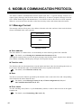
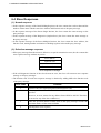
Message Format ...........................................................................................44
Function Code ...............................................................................................45
Communication Mode ...................................................................................45
Slave Responses ..........................................................................................46
Calculating CRC-16.......................................................................................47
IMR01H02-E3
i-3
Page
6.6 Message Format............................................................................................49
6.6.1 Read holding registers [03H] ............................................................................49
6.6.2 Preset single register [06H] ..............................................................................50
6.6.3 Diagnostics (loopback test) [08H] .....................................................................51
6.6.4 Preset multiple registers [10H]..........................................................................52
6.7 Data Configuration ........................................................................................52
6.7.1 Data range........................................................................................................53
6.7.2 Data processing precautions ............................................................................54
6.8 Communication Data List ..............................................................................55
6.9 Data Map.......................................................................................................62
6.9.1 Reference to data map .....................................................................................62
6.9.2 Data map list.....................................................................................................63
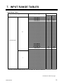
7. INPUT RANGE TABLES.....................................................75
8. TROUBLESHOOTING ........................................................79
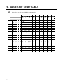
9. ASCII 7- BIT CODE TABLE ................................................82
i-4
IMR01H02-E3
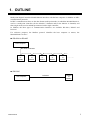
1. OUTLINE
Multi-point Digital Controller MA900/MA901 interfaces with the host computer via Modbus or RKC
communication protocols.
In RKC communication, there are the data format (multi-point mode) in which the MA900/MA901 is
used as a multi-point controller (for the MA900: 4 channels and for the MA901: 8 channels) and
that (single mode) used as multidrop-connected with a single controller.
In addition, the three types of communication interfaces are available: RS-422A, RS-485 and
RS-232C.
For reference purposes, the Modbus protocol identifies the host computer as master, the
MA900/MA901 as slave.
!"RS-422A or RS-485
Host computer
RS-422A or RS-485
MA900
or
MA901
MA900
or
MA901
MA900
or
MA901
MA900
or
MA901
MA900
or
MA901
・・・・・・・・・
!"RS-232C
Host computer
IMR01H02-E3
RS-232C
MA900
or
MA901
1
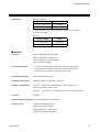
2. SPECIFICATIONS
RKC communication
!"
Interface:
Based on RS-422A, EIA standard
Based on RS-485, EIA standard
Based on RS-232C, EIA standard
(Specify when ordering)
Connection method:
4-wire system, half-duplex multi-drop connection (RS-422A)
2-wire system, half-duplex multi-drop connection (RS-485)
3-wire system, point-to-point connection (RS-232C)
Synchronous method:
Start-stop synchronous type
Communication speed:
2400 bps, 4800 bps, 9600 bps, 19200 bps
Data bit configuration:
Start bit:
Data bit:
Parity bit:
Stop bit:
Protocol:
ANSI X3.28 subcategory 2.5, A4
Polling/selecting type
Error control:
Vertical parity (With parity bit selected)
Horizontal parity (BCC check)
Communication code:
ASCII 7-bit code
Termination resistor:
Externally connected (RS-485)
Xon/Xoff control:
None
Maximum connections:
Multi-point mode (MA900/MA901)
RS-422A, RS-485: 32 instruments maximum including a host computer
RS-232C:
1 instrument
1
7 or 8
Without, Odd or Even
1 or 2
Single mode (MA900) *
RS-422A, RS-485: 26 instruments maximum including a host computer
RS-232C:
1 instrument
Single mode (MA901) *
RS-422A, RS-485: 13 instruments maximum including a host computer
RS-232C:
1 instrument
* As the address setting range is from 00 to 99, addresses corresponding to four
MA900s or eight MA901s are used in the single mode.
Therefore, the connectable number of sets is limited.
2
IMR01H02-E3
2. SPECIFICATIONS
Signal logic:
RS-422A, RS-485
Signal voltage
Logic
V (A) - V (B) ≥ 2 V
0 (SPACE)
V (A) - V (B) ≤ -2 V
1 (MARK)
Voltage between V (A) and V (B) is the voltage of (A) terminal
for the (B) terminal.
RS-232C
Signal voltage
Logic
+3 V or more
0 (SPACE)
-3 V or less
1 (MARK)
Modbus
!"
Interface:
Based on RS-422A, EIA standard
Based on RS-485, EIA standard
Based on RS-232C, EIA standard
(Specify when ordering)
Connection method:
4-wire system, half-duplex multi-drop connection (RS-422A)
2-wire system, half-duplex multi-drop connection (RS-485)
3-wire system, point-to-point connection (RS-232C)
Synchronous method:
Start/stop synchronous type
Communication speed:
2400 bps, 4800 bps, 9600 bps, 19200 bps
Data bit configuration:
Data bit: 8 (Byte data corresponding to binary data or bit.)
Parity bit: Without, Odd or Even
Stop bit: 1 or 2 (However, with the parity bit selected: 1 bit fixed)
Protocol:
Modbus
Signal transmission mode: Remote Terminal Unit (RTU) mode
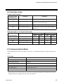
Function code:
IMR01H02-E3
03H (Read holding registers)
06H (Preset single register)
08H (Diagnostics: loopback test)
10H (Preset multiple registers)
3
2. SPECIFICATIONS
Error check method:
CRC-16
Error code:
1: Function code error
2: When any address other than 0000H to 02EEH and 1388H to 14A0H
are specified
3: When the specified number of data items in the query message
exceeds the maximum number of data items available
4: Self-diagnostic error response
Termination resistor:
Externally connected (RS-485)
Maximum connections:
RS-422A, RS-485: 32 instruments maximum including a master
RS-232C:
1 instrument
Signal logic:
RS-422A, RS-485
Signal voltage
Logic
V (A) - V (B) ≥ 2 V
0 (SPACE)
V (A) - V (B) ≤ -2 V
1 (MARK)
Voltage between V (A) and V (B) is the voltage of (A) terminal
for the (B) terminal.
RS-232C
Signal voltage
4
Logic
+3 V or more
0 (SPACE)
-3 V or less
1 (MARK)
IMR01H02-E3
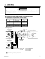
3. WIRING
WARNING
!
To prevent electric shock or instrument failure, do not turn on the power until all
the wiring is completed.
Connection to the RS-422A port of the host computer (master)
!"
#"Communication terminal number and signal details
Terminal No.
Signal name
Symbol
44
Signal ground
SG
45
Send data
T (A)
46
Send data
T (B)
47
Receive data
R (A)
48
Receive data
R (B)
#"Wiring method
MA900/MA901
(Slave)
RS-422A
Paired wire
SG 44
Host computer (Master)
SG
T (A) 45
T (A)
T (B) 46
T (B)
R (A) 47
R (A)
R (B) 48
R (B)
Communication terminals
$
$
$
MA900/MA901
(Slave)
Shielded twisted
pair wire
SG 44
T (A) 45
T (B) 46
R (A) 47
R (B) 48
Communication terminals
Maximum connections: Multi-point mode:
Single mode:
31 instruments (MA900/MA901)
25 instruments (MA900)
12 instruments (MA901)
The cable is provided by the customer.
IMR01H02-E3
5
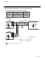
3. WIRING
Connection to the RS-485 port of the host computer (master)
!"
#"Communication terminal number and signal details
Terminal No.
Signal name
Symbol
44
Signal ground
SG
45
Send data/Receive data
T/R (A)
46
Send data/Receive data
T/R (B)
#"Wiring method
MA900/MA901
(Slave)
RS-485 Paired wire
SG 44
Host computer (Master)
SG
T/R (A) 45
T/R (A)
T/R (B) 46
T/R (B)
*R
Shielded twisted
pair wire
Communication terminals
$
$
$
MA900/MA901
(Slave)
SG 44
T/R (A) 45
T/R (B) 46
Communication terminals
*R: Termination resistors
(Example: 120 Ω 1/2 W)
*R
Maximum connections: Multi-point mode: 31 instruments (MA900/MA901)
Single mode:
25 instruments (MA900)
Single mode:
12 instruments (MA901)
The cable is provided by the customer.
6
IMR01H02-E3
3. WIRING
Connection to the RS-232C port of the host computer (master)
!"
#"Communication terminal number and signal details
Terminal No.
Signal name
Symbol
44
Signal ground
SG (GND)
45
Send data
SD (TXD)
46
Receive data
RD (RXD)
#"Wiring method
MA900/MA901
(Slave)
Host computer (Master)
RS-232C
SG (GND)
44
SG (GND)
SD (TXD)
45
SD (TXD)
RD (RXD)
46
RD (RXD)
*
RS (RTS)
Shielded wire
CS (CTS)
Communication terminals
Number of connection: 1 instrument
* Short RS and CS within connector.
The cable is provided by the customer.
Connection example (For the MA900/MA901 multi-point mode)
!"
Connection with up to 31 MA900/MA901 (slaves) and one host computer (master)
Host computer (Master)
RS-422A
or
RS-485
Junction terminals
Device address
(Slave address)
1
2
3
MA900/MA901
(Slave)
IMR01H02-E3
4
29
30
31
MA900/MA901
(Slave)
7
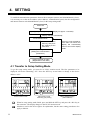
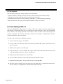
4. SETTING
To establish communication parameters between host computer (master) and MA900/MA901 (slave),
it is necessary to set the device address (slave address), communication speed, data bit configuration
and interval time on each MA900/MA901 (slave) in the setup setting mode.
Power ON
Input Type/Input Range Display
(Display for approx. 4 seconds)
Display changes automatically
PV/SV Monitor Mode
If the key is not pressed for
more than one minute, the
display will automatically
return to the PV/SV display
mode.
Press and hold the
SET key and press
the <R/S key at the
same time
Setup Setting Mode
(Setting the communication
parameters)
Power is turned on again
(Registration of set value)
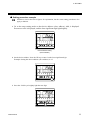
4.1 Transfer to Setup Setting Mode
To go the setup setting mode, you must be in PV/SV monitor mode. The first parameter to be
displayed will be the autotuning, ATU. Press the SET key several times to change to the device
address “Add.”
CH
PV
CH
PV
CH
PV
AREA
SV
AREA
SV
AREA
SV
SET
CH
R/S
MA900
PV/SV monitor mode
CH
SET
R/S
CH
SET
R/S
MA900
MA900
Setup setting mode
Autotuning (AT) setting
Device address setting
(Slave address)
When let setup setting mode finish, press and hold the SET key and press the <R/S key at
the same time. The display changes to the PV/SV monitor mode.
MA900 is used in the above figures for explanation, but the same setting procedures also
apply to MA901.
8
IMR01H02-E3
4. SETTING
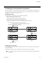
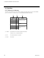
4.2 Setting the Communication Parameters
To select parameters in setup setting mode, press the SET key. The parameters are displayed and
sequenced in the order of device address (slave address), Add, communication speed, bPS, data bit
configuration, bIT and interval time set value, InT.
Setting procedure
!"
Setting procedure vary depending on the communication parameter.
• Device address Add, interval time InT
Operate UP, DOWN and <R/S key, and input numerals.
• Communication speed bPS, data bit configuration bIT
Operate UP or DOWN key, and choose one among the displayed set value.
For MA900: Proportioning cycle time setting (heat control) or
Cool-side proportioning cycle time setting (heat/cool control)
For MA901: Proportioning cycle time setting
Press the SET key.
CH
PV
AREA
SV
Press the SET key.
CH
PV
AREA
SV
Communication speed
[bPS]
Device address [Add]
(Slave address)
Press the SET key.
CH
PV
AREA
SV
Press the SET key.
Interval time [InT]
Press the SET key.
CH
PV
AREA
SV
Data bit configuration
[bIT]
Scan interval time
Registration of set value
!"
After completing all communication parameter settings, turn on the power again, and register the set
value which changed.
After the power is turned on again, communication is mode using the set value changed.
Not by turning the power on again, the set value can also be registered by changing to RUN
from STOP.
IMR01H02-E3
9
4. SETTING
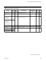
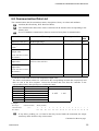
Description of each parameters
!"
Symbol
Name
Device address
(Slave address)
Setting range
0 to 99
(See P.16, 17)
(Add)
(bPS)
(bIT)
Communication 240: 2400 bps
speed
480: 4800 bps
960: 9600 bps
1920: 19200 bps
Data bit
See data bit
configuration
configuration
table
Interval time *
0 to 250 ms
(InT)
Description
Set it not to duplication in multidrop connection.
If the slave address is set to 0 in
Modbus, two-way communication
cannot be performed.
Set the same communication
speed for both the MA900/MA901
(slave) and the host computer
(master).
Set the same data bit configuration
for both the MA900/MA901
(slave) and the host computer
(master).
The MA900’s or MA901’s
interval time must match the
specifications of the host
computer.
Factory
set value
0
960
8n1
10
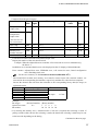
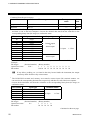
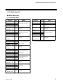
Data bit configuration table
Set value
(8n1)
(8n2)
(8E1)
(8E2) 1
(8o1)
(8o2) 1
(7n1) 1
(7n2) 1
(7E1) 1
(7E2) 1
(7o1) 1
(7o2) 1
1
Data bit
8
8
8
8
8
8
7
7
7
7
7
7
Parity bit
Without
Without
Even
Even
Odd
Odd
Without
Without
Even
Even
Odd
Odd
Stop bit
1
2
1
2
1
2
1
2
1
2
1
2
Setting range of
Modbus
Setting range of
RKC communication
When the Modbus communication protocol selected, this setting becomes invalid.
* The interval time for the MA900/MA901 should be set to provide a time for host computer to finish
sending all data including stop bit and to switch the line to receive data. If the interval time between
the two is too short, the MA900/MA901 may send data before the host computer is ready to receive
it. In this case, communication transmission can not be conducted correctly. For a successful
communication sequence to occur, the MA900’s or MA901’s interval time must match the
specifications of the host computer.
No setting can be changed when “1: Lock” is selected by the lock level 1.
#).
For the lock level 1, see the Instruction Manual (IMR01H01-E#
10
IMR01H02-E3
4. SETTING
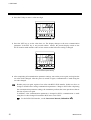
Setting procedure example
!"
MA900 is used in the below figures for explanation, but the same setting procedures also
apply to MA901.
1. Go to the setup setting mode so that device address (slave address), Add, is displayed.
Present set value is displayed, and the least significant digit light brightly.
CH
PV
AREA
SV
CH
SET
R/S
MA900
Device address setting
(Slave address)
2. Set the device address. Press the UP key to enter 5 at the least significant digit.
Example: Setting the device address (slave address) to 15.
CH
PV
AREA
SV
CH
SET
R/S
MA900
3. Press the <R/S key to brightly light the tens digit.
CH
PV
AREA
SV
CH
SET
R/S
MA900
IMR01H02-E3
11
4. SETTING
4. Press the UP key to enter 1 at the tens digit.
CH
PV
AREA
SV
CH
SET
R/S
MA900
5. Press the SET key to set the value thus set. The display changes to the next communication
parameter. It the SET key is not pressed within 1 minute, the present display returns to the
PV/SV monitor mode and the value set here returns to that before the setting is changed.
CH
PV
AREA
SV
CH
SET
R/S
MA900
Communication speed setting
6. After completing all communication parameter settings, turn on the power again, and register the
set value which changed. After the power is turned on again, communication is made using the
set value changed.
Besides power on again, register of set value with RUN/ STOP transfer. In this case, have to
change to STOP before setting communication parameter. Change to RUN after completing
the communication parameter settings, the instrument performs the same operation as that at
the time of power on again.
In addition, it the communication parameter is changed at RUN, communication is made
using the set value changed if returned to RUN once set to STOP.
$).
For the RUN/STOP transfer, see the Instruction Manual (IMR01H01-E$
12
IMR01H02-E3
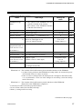
4. SETTING
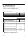
4.3 Communication Requirements
Processing times during data send/receive
!"
The MA900/MA901 requires the following processing times during data send/receive.
Whether the host computer is using either the polling or selecting procedure for communication, the
following processing times are required for MA900/MA901 to send data:
-Response wait time after MA900/MA901 sends BCC in polling procedure
-Response wait time after MA900/MA901 sends ACK or NAK in selecting procedure
RKC communication (Polling procedure)
Procedure details
Response send time after MA900/MA901 receives ENQ
Response send time after MA900/MA901 receives ACK
Response send time after MA900/MA901 receives NAK
Response send time after MA900/MA901 sends BCC
Time (ms)
MIN
TYP
MAX
1
1
1
−
2
−
−
−
4
4
4
1
RKC communication (Selecting procedure)
Procedure details
Response send time after MA900/MA901 receives BCC
Response wait time after MA900/MA901 sends ACK
Response wait time after MA900/MA901 sends NAK
Time (ms)
MIN
TYP
MAX
1
−
−
2
−
−
3
1
1
Modbus
Procedure details
Read holding registers [03H]
Response transmission time after the slave receives the query
message
Preset single register [06H]
Response transmission time after the slave receives the query
message
Diagnostics (loopback test) [08H]
Response transmission time after the slave receives the query
message
Preset multiple registers [10H]
Response transmission time after the slave receives the query
message
Time
20 ms max.
3 ms max.
3 ms max.
20 ms max.
Response send time is time at having set interval time in 0 ms.
IMR01H02-E3
13
4. SETTING
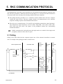
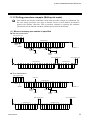
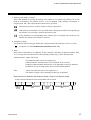
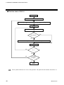
RS-485 (2-wire system) send/receive timing
!"
The sending and receiving of RS-485 communication is conducted through two wires; consequently,
the transmission and reception of data requires precise timing. Typical polling and selecting
procedures between the host computer and MA900/MA901 are described below:
%"Polling procedure
Send data
(Possible/Impossible)
Host computer
Possible
Impossible
E
O
T
Sending status
Send data
(Possible/Impossible)
Controller
-----
A
C
K
E
N
Q
Possible
a
b
N
or A
K
c
Impossible
S
T
X
Sending status
-----
B
C
C
a: Response send time after MA900/MA901 receives [ENQ] + Interval time
b: Response send time after MA900/MA901 sends BCC
c: Response send time after MA900/MA901 receives [ACK] + Interval time or
Response send time after MA900/MA901 receives [NAK] + Interval time
%"Selecting procedure
Send data
(Possible/Impossible)
Host computer
Possible
Impossible
S
T
X
Sending status
Send data
(Possible/Impossible)
Controller
Sending status
Possible
-----
B
C
C
a
b
Impossible
A
N
C or A
K
K
a: Response send time after MA900/MA901 receives BCC + Interval time
b: Response wait time after MA900/MA901 sends ACK or Response wait time after MA900/MA901
sends NAK
To switch the host computer from transmission to reception, send data must be on line. To
check if data is on line, do not use the host computer’s transmission buffer but confirm it by
the shift register.
Whether the host computer is using either the polling or selecting procedure for
communication, the following processing times are required for MA900/MA901 to send data:
-Response wait time after MA900/MA901 sends BCC in polling procedure
-Response wait time after MA900/MA901 sends ACK or NAK in selecting procedure
RS-422A/RS-485 Fail-safe
!"
A transmission error may occur with the transmission line disconnected, shorted or set to the highimpedance state. In order to prevent the above error, it is recommended that the fail-safe function be
provided on the receiver side of the host computer. The fail-safe function can prevent a framing error
from its occurrence by making the receiver output stable to the MARK (1) when the transmission line
is in the high-impedance state.
14
IMR01H02-E3
5. RKC COMMUNICATION PROTOCOL
The MA900/MA901 (hereafter, called controller) uses the polling/selecting method to establish a data
link. The basic procedure is followed ANSI X3.28 subcategory 2.5, A4 basic mode data transmission
control procedure (Fast selecting is the selecting method used in this controller).
!"The polling/selecting procedures are a centralized control method where the host computer
controls the entire process. The host computer initiates all communication so the controller
responds according to queries and commands from the host.
!"The code use in communication is 7-bit ASCII code including transmission control characters.
The transmission control characters are EOT (04H), ENQ (05H), ACK (06H), NAK (15H),
STX (02H) and ETX (03H). The figures in the parenthesis indicate the corresponding
hexadecimal number.
In RKC communication, both multi-point and single modes are available. If the single mode
is required, contact our sales office or agent.
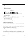
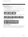
5.1 Polling
Polling is the action where the host computer requests one of the connected controllers to transmit
data. An example of the polling procedure is shown below:
Host computer send
E
O
T
[Address] [
(1)
] [ ID ]
(2)
Memory area
number
E
N
Q
Controller send
Host
computer
send
Controller
send
E
O
T
No response
(5)
E
O
T (4)
S
E
T [ ID ] [ Data ] T [ BCC ]
X
X
(3)
Host
computer
send
(10)
No (8)
response
(9)
Time
out
E
O
T
Indefinite
A (6)
C
N
K
A
(7) K
ID: Identifier
IMR01H02-E3
15
5. RKC COMMUNICATION PROTOCOL
5.1.1 Polling procedures
(1) Data link initialization
Host computer sends EOT to the controllers to initiate data link before polling sequence.
(2) Data sent from host computer - Polling sequence
The host computer sends the polling sequence in the following two types of formats:
• Format in which no memory area number is specified, and
• Format in which the memory area number is specified.
#"When no memory area number is specified
To be sent in this format for any identifier not corresponding to the memory area.
1.
3.
Example:
4.
ENQ
0
1
M
1
ENQ
Address Identifier
#"When the memory area number is specified
To be sent in this format for any identifier corresponding to the memory area.
1.
2.
3.
K
4.
ENQ
Example:
0
1
K
1
S
1
ENQ
Address Memory Identifier
area
number
1. Address (2 digits)
• Multi-point mode
The device address specifies the controller to be polled and each controller must have its own
unique device address.
For details, see 4.2 Setting the Communication Parameters (P. 9).
16
IMR01H02-E3
5. RKC COMMUNICATION PROTOCOL
• Single mode
This data represents the device address and channel number of the controller to be polled. When
polling any identifier without the corresponding channel number, the channel number is ignored.
Each address is calculated as follows.
Calculation method of address:
Address = Device address of controller + Controller channel number - 1
Example: When 3 controllers (MA900: 4 channels) are multidrop-connected
Device address
of controller
Controller
channel number
Addresses used in
polling sequence
Controller 1
Device address 00 + CH1 - 1 = Address 00
Device address 00 + CH2 - 1 = Address 01
Device address 00 + CH3 - 1 = Address 02
Device address 00 + CH4 - 1 = Address 03
Controller 2
Device address 04 + CH1 - 1 = Address 04
Device address 04 + CH2 - 1 = Address 05
Device address 04 + CH3 - 1 = Address 06
Device address 04 + CH4 - 1 = Address 07
Controller 3
Device address 08 + CH1 - 1 = Address 08
Device address 08 + CH2 - 1 = Address 09
Device address 08 + CH3 - 1 = Address 10
Device address 08 + CH4 - 1 = Address 11
For example, if Address 10 is
selected CH3 corresponding to
Controller 3 is urged to send
data.
Set the device address number of the succeeding controller to four or more than four plus the same
number of the previous controller. Otherwise (for example, if set to 00, 01 and 02 between Controllers
1, 2 and 3), the address used for polling is duplicated and as a result no normal communication can be
made.
In case of the MA901:
Set the device address number of the succeeding controller to eight or more than eight plus the
same number of the previous controller.
Controller 1: Device address 00, Controller 2: Device address 08, ..........
2. Memory area number (2 digits)
This is the identifier to specify the memory area number. It is expressed by affixing “K” to the
head of each memory area number (from 1 to 8). In addition, if the memory area number is
assigned with “K0,” this represents that control area is specified.
The memory area now used for control is called “Control area.”
If the memory area number is not specified when polling the identifier corresponding to
the memory area, this represents that the control area is specified.
If any identifier not corresponding to the memory area is assigned with a memory area
number, this memory area number is ignored.
IMR01H02-E3
17
5. RKC COMMUNICATION PROTOCOL
3. Identifier (2 digits)
The identifier specifies the type of data that is requested from the controller.
For details, see 5.3 Communication Identifier List (P. 34).
4. ENQ
The ENQ is the transmission control character that indicates the end of the polling sequence.
The ENQ must be attached to the end of the identifier.
The host computer then must wait for a response from the controller.
(3) Data sent from the controller
If the polling sequence is received correctly, the controller sends data in the following format:
1.
2.
3.
4.
5.
STX
Identifier
Data
ETX
BCC
1. STX
STX is the transmission control character which indicates the start of the text transmission
(identifier and data).
2. Identifier (2 digits)
The identifier indicates the type of data (measured value, status and set value) sent to the host
computer.
For details, see 5.3 Communication Identifier List (P. 34).
3. Data
Data which is indicated by an identifier of this controller, consisting of channel numbers, data,
etc. It is expressed in decimal ASCII code including a minus sign (-) and a decimal point.
Channel number: 2 digit ASCII code, not zero-suppressed.
(Channel number: MA900: from 01 to 04, MA901: from 01 to 08)
Channels without channel numbers may exist depending on the type identifier.
In addition, in case of single mode, do not use the channel number.
Data:
ASCII code. The number of digits varies depending on the type of identifier.
Multi-point mode: Zero-suppressed with spaces (20H).
Single mode:
Not zero-suppressed.
Data structure of identifier with channel number (Only for multi-point mode)
A data is divided from that of the next channel with a comma.
,
Channel
number
Data
Space
Channel
Comma number
,
Data
Space
Comma
For the identifier without the corresponding channel number, the same data is sent to the
host computer regardless of the channel number.
18
IMR01H02-E3
5. RKC COMMUNICATION PROTOCOL
4. ETX
ETX is a transmission control character used to indicate the end of text transmission.
5. BCC
BCC (Block Check Character) detects error using horizontal parity and is calculated by
horizontal parity (even number).
Calculation method of BCC: Exclusive OR all data and characters from STX through ETX, not
including STX.
Example:
STX
M
1
0
0
0
5
0
0
4DH 31H 30H 30H 30H 35H 30H 30H
ETX
03H
BCC
Hexadecimal numbers
BCC = 4DH ⊕ 31H ⊕ 30H ⊕ 30H ⊕ 30H ⊕ 35H ⊕ 30H ⊕ 30H ⊕ 03H = 7AH
Value of BCC becomes 7AH.
(4) EOT sent from the controller (Ending data transmission from the controller)
In the following cases, the controller sends EOT to terminate the data link:
• When the specified identifier is invalid
• When there is an error in the data type
• When data is not sent from the host computer even if the data link is initialized
• When all the data has been sent
(5) No response from the controller
The controller will not respond if the polling address is not received correctly. It may be necessary for
the host computer to take corrective action such as a time-out.
(6) ACK (Acknowledgment)
An acknowledgment ACK is sent by the host computer when data received is correct. When the
controller receives ACK from the host computer, the controller will send any remaining data of the
next identifier without additional action from the host computer.
For the identifier, see # Communication identifier list (P. 35).
When host computer determines to terminate the data link, EOT is sent from the host computer.
(7) NAK (Negative acknowledge)
If the host computer does not receive correct data from the controller, it sends a negative
acknowledgment NAK to the controller. The controller will re-send the same data when NAK is
received. This cycle will go on continuously until either recovery is achieved or the data link is
corrected at the host computer.
IMR01H02-E3
19
5. RKC COMMUNICATION PROTOCOL
(8) No response from host computer
When the host computer does not respond within approximately three seconds after the controller
sends data, the controller sends EOT to terminate the data link. (Time out: 3 seconds)
(9) Indefinite response from host computer
The controller sends EOT to terminate the data link when the host computer response is indefinite.
(10) EOT (Data link termination)
The host computer sends EOT message when it is necessary to suspend communication with the
controller or to terminate the data link due lack of response from the controller.
20
IMR01H02-E3
5. RKC COMMUNICATION PROTOCOL
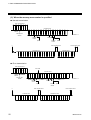
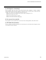
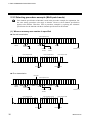
5.1.2 Polling procedure example (Multi-point mode)
Four channels specification of MA900 is used in the procedure example for explanation, but
the same setting procedures also apply to MA901. However, the 8-channel specification
applies to the MA901. Therefore, refer to procedure examples by replacing the 4-channel
specification for the MA900 with the 8-channel specification for the MA901.
(1) When no memory area number is specified
!"Normal transmission
Host computer send
E
O 0
T
E
0 M 1 N
Q
Controller send
S
T M 1
X
Device
address
0
1
1
0
0
.
0
,
0
2
2
0
0
.
0
,
Identifier
Identifier
Data
Channel
number
Comma
Space
Channel
number
*1
Space
Host computer send
Host computer send
A
C
K
E
O
T
Controller send
0
3
3
0
0
.
Continue to *1
Data
0
,
0
4
4
0
0
.
0
Controller send
S
T M 2
X
E B
T C
X C
0
E B
...... T C
X C
1
!"Error transmission
Host computer send
E
O 0
T
E
0 M 1 N
Q
Error data
Controller send
S
T M 1
X
Device
address
0
1
1
0
0
.
0
,
0
2
2
0
0
.
0
,
......
Identifier
Identifier
Data
Channel
number
Comma
Channel
number
Space
*1
IMR01H02-E3
4
4
0
0
.
0
Space
Host computer send
Host computer send
N
A
K
E
O
T
Controller send
...... 0
Continue to *1
Data
E B
T C
X C
Controller re-send
S
T M 1
X
0
1
1
0
0
.
0
,
E B
...... T C
X C
21
5. RKC COMMUNICATION PROTOCOL
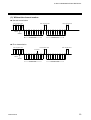
(2) When the memory area number is specified
!"Normal transmission
Host computer send
E
O 0
T
0
K
1
S
E
1 N
Q
Controller send
S
T S
X
Identifier
Device
address
Memory area
number
1
0
1
1
0
Identifier
0
.
0
,
0
2
2
0
Data
0
.
0
,
Continue to *1
Data
Channel
number
Comma
Space
Channel
number
Space
Host computer send
*1
Controller send
0
3
3
0
0
.
0
,
0
Host computer send
A
C
K
4
4
0
0
.
0
E
O
T
Controller send
E B
T C
X C
S
T A
X
1
0
1
0
.
0
,
E B
...... T C
X C
!"Error transmission
Host computer send
E
O 0
T
0
K
1
Device
address
S
E
1 N
Q
Error data
Controller send
S
T S
X
Identifier
Memory area
number
1
0
1
1
Identifier
0
0
.
0
,
*1
22
0
0
.
0
0
......
Continue to *1
Comma
Channel
number
Space
Host computer send
Host computer send
N
A
K
E
O
T
Controller send
4
2
Data
Space
4
2
Data
Channel
number
...... 0
0
E B
T C
X C
Controller re-send
S
T S
X
1
0
1
1
0
0
.
0
,
E B
...... T C
X C
IMR01H02-E3
5. RKC COMMUNICATION PROTOCOL
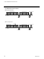
(3) Without the channel number
!"Normal transmission
Host computer send
E
O 0
T
0
T
Host computer send
Host computer send
A
C
K
E
O
T
E
L N
Q
S
T T
X
Device
address
2
L
E B
T C
X C
S
T
X
I
0
P
E B
T C
X C
Identifier
Identifier
Data
Identifier
Controller send
Data
Controller send
!"Error transmission
Host computer send
E
O 0
T
0
T
Host computer send
E
L N
Q
Device
address
S
T T
X
2
L
Host computer send
N
A
K
Error data
E B
T C
X C
E
O
T
S
T T
X
2
L
E B
T C
X C
Identifier
Identifier
Data
Controller send
IMR01H02-E3
Identifier
Data
Controller re-send
23
5. RKC COMMUNICATION PROTOCOL
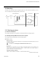
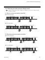
5.1.3 Polling procedure example (Single mode)
MA900 is used in the procedure example for explanation, but the same setting procedures
also apply to MA901.
(1) When no memory area number is specified
!"Normal transmission
Host computer send
E
O 0
T
Host computer send
Host computer send
A
C
K
E
O
T
E
0 M 1 N
Q
S
T M 1
X
Address
0
1
0
0
.
0
E B
T C
X C
S
T M 2
X
0
0
5
0
.
0
E B
T C
X C
Identifier
Identifier
Data
Identifier
Controller send
Data
Controller send
!"Error transmission
Host computer send
E
O 0
T
E
0 M 1 N
Q
Host computer send
Host computer send
N
A
K
E
O
T
Error data
S
T M 1
X
Address
0
1
0
0
0
E B
T C
X C
S
T M 1
X
0
1
0
0
.
0
E B
T C
X C
Identifier
Identifier
Identifier
Data
Controller send
Data
Controller re-send
(2) When the memory area number is specified
!"Normal transmission
Host computer send
E
O 0
T
0
K
1
Address
S
Host computer send
Host computer send
A
C
K
E
O
T
E
1 N
Q
Identifier
Memory area
number
S
T S
X
1
0
1
Identifier
0
0
.
0
E B
T C
X C
S
T A
X
1
0
2
Identifier
Data
Controller send
0
0
.
0
E B
T C
X C
Data
Controller send
!"Error transmission
Host computer send
E
O 0
T
0
Address
K
1
S
E
1 N
Q
Identifier
Memory area
number
Host computer send
N
A
K
E
O
T
Error data
S
T S
X
1
Identifier
0
1
0
0
Data
Controller send
24
Host computer send
0
E B
T C
X C
S
T S
X
1
0
Identifier
1
0
0
.
0
E B
T C
X C
Data
Controller re-send
IMR01H02-E3
5. RKC COMMUNICATION PROTOCOL
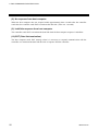
5.2 Selecting
Selecting is the action where the host computer requests one of the connected controllers to receive
data. An example of the selecting procedure is shown below:
Controller send
Host computer send
E
O
T
[Address]
(1)
(2)
S
T [
X
][
E
] [Data] T [BCC]
X
(3)
Identifier
Memory area
number
No response
(6)
A
C
K
(4)
N
A
K
(5)
Host computer
send
E
O
T
(7)
5.2.1 Selecting procedures
(1) Data link initialization
Host computer sends EOT to the controllers to initiate data link before selecting sequence.
(2) Sending selecting address from the host computer
Host computer sends selecting address for the selecting sequence.
!"Address (2 digits)
• Multi-point mode
The device address specifies the controller to be selected and each controller must have its own
unique device address.
For details, see 4.2 Setting the Communication Parameters (P. 9).
• Single mode
This data is for representing the device address and channel number of the controller to be
selected. When selecting any identifier without a channel number, that channel number is
ignored. Each address is calculated as follows.
Calculation method of address:
Address = Device address of controller + Controller channel number - 1
Continued on the next page.
IMR01H02-E3
25
5. RKC COMMUNICATION PROTOCOL
Continued from the previous page.
Example: When 3 controllers (MA900: 4 channels) are multidrop-connected
Device address
of controller
Controller
channel number
Addresses used in
selecting sequence
Controller 1
Device address 00 + CH1 - 1 = Address 00
Device address 00 + CH2 - 1 = Address 01
Device address 00 + CH3 - 1 = Address 02
Device address 00 + CH4 - 1 = Address 03
Controller 2
Device address 04 + CH1 - 1 = Address 04
Device address 04 + CH2 - 1 = Address 05
Device address 04 + CH3 - 1 = Address 06
Device address 04 + CH4 - 1 = Address 07
Controller 3
Device address 08 + CH1 - 1 = Address 08
Device address 08 + CH2 - 1 = Address 09
Device address 08 + CH3 - 1 = Address 10
Device address 08 + CH4 - 1 = Address 11
For example, if Address 10 is
selected CH3 corresponding to
Controller 3 is urged to receive
data.
Set the device address number of the succeeding controller to four or more than four plus the same
number of the previous controller. Otherwise (for example, if set to 00, 01 and 02 between Controllers
1, 2 and 3), the address used for polling is duplicated and as a result no normal communication can be
made.
In case of the MA901:
Set the device address number of the succeeding controller to eight or more than eight plus the
same number of the previous controller.
Controller 1: Device address 00, Controller 2: Device address 08, ..........
As long as the data link is not initialized by sending or receiving EOT, the selecting address
once sent becomes valid.
(3) Data sent from the host computer
The host computer sends data for the selecting sequence with the following format:
!"When no memory area number is specified
2.
3.
STX
Identifier
Data
!"When the memory area number is specified
1.
2.
STX
Memory area
number
Identifier
ETX
BCC
3.
Data
ETX
BCC
For the STX, ETX and BCC, see 5.1 Polling (P. 15).
26
IMR01H02-E3
5. RKC COMMUNICATION PROTOCOL
1. Memory area number (2 digits)
This is the identifier to specify the memory area number. It is expressed by affixing “K” to the
head of each memory area number (from 1 to 8). In addition, if the memory area number is
assigned with “K0,” this represents that control area is specified.
The memory area now used for control is called “Control area.”
If the memory area number is not specified when selecting the identifier corresponding to
the memory area, selecting is made to the memory area.
If any identifier not corresponding to the memory area is assigned with a memory area
number, this memory area number is ignored.
2. Identifier (2 digits)
The identifier specifies the type of data that is requested from the controller, such as set value.
For details, see 5.3 Communication Identifier List (P. 34).
3. Data
Data which is indicated by an identifier of this controller, consisting of channel numbers, data,
etc. It is expressed in decimal ASCII code including a minus sign (-) and a decimal point.
Channel number: 2 digit ASCII code
The channel number can be zero-suppressed.
(Channel number: MA900: from 01 to 04, MA901: from 01 to 08)
Channels without channel numbers may exist depending on the type identifier.
In addition, in case of single mode, do not use the channel number.
Data:
ASCII code (The data can be zero-suppressed.)
The number of digits varies depending on the type of identifier.
Data structure of identifier with channel number (Only for multi-point mode)
A data is divided from that of the next channel with a comma.
,
Channel
number
IMR01H02-E3
Data
Space
Comma
,
Channel
number
Data
Space
Comma
27
5. RKC COMMUNICATION PROTOCOL
#"About numerical data
The data that receipt of letter is possible
• Data with numbers below the decimal point omitted or zero-suppressed data can be received.
(Number of digits: Within 6 digits)
<Example> When data send with -001.5, -01.5, -1.5, -1.50, -1.500 at the time of -1.5, controller
can receive a data.
• When the host computer send data with decimal point to item of without decimal point, controller
receives a message with the value which cut off below the decimal point.
<Example> When setting range is 0 to 200, controller receives as a following.
Send data
Receive data
0.5
100.5
0
100
• Controller receives value in accordance with decided place after the decimal point. The value
below the decided place after the decimal point is cut off.
<Example> When setting range is -10.00 to +10.00, controller receives as a following.
Send data
Receive data
-.5
-.058
.05
-0
-0.50
-0.05
0.05
0.00
The data that receipt of letter is impossible
Controller sends NAK when received a following data.
+
Plus sign and the data that gained plus sing
-
Only minus sign (there is no figure)
.
Only decimal point (period)
-.
Only minus sign and decimal point (period)
(4) ACK (Acknowledgment)
An acknowledgment ACK is sent by the controller when data received is correct. When the host
computer receives ACK from the controller, the host computer will send any remaining data. If there
is no more data to be sent to controller, the host computer sends EOT to terminate the data link.
28
IMR01H02-E3
5. RKC COMMUNICATION PROTOCOL
(5) NAK (Negative acknowledge)
If the controller does not receive correct data from the host computer, it sends a negative
acknowledgment NAK to the host computer. Corrections, such as re-send, must be made at the host
computer. The controller will send NAK in the following cases:
• When an error occurs on communication the line (parity, framing error, etc.)
• When a BCC check error occurs
• When the specified identifier is invalid
• When receive data exceeds the setting range
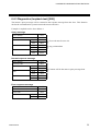
(6) No response from controller
The controller does not respond when it can not receive the selecting address, STX, ETX or BCC.
(7) EOT (Data link termination)
The host computer sends EOT when there is no more data to be sent from the host computer or there
is no response from the controller.
IMR01H02-E3
29
5. RKC COMMUNICATION PROTOCOL
5.2.2 Selecting procedure example (Multi-point mode)
Four channels specification of MA900 is used in the procedure example for explanation, but
the same setting procedures also apply to MA901. However, the 8-channel specification
applies to the MA901. Therefore, refer to procedure examples by replacing the 4-channel
specification for the MA900 with the 8-channel specification for the MA901.
(1) When no memory area number is specified
!"Normal transmission
Host computer send
E
O 0
T
0
S
T S
X
1
0
1
0
1
Identifier
Device
address
0
0
.
0
,
0
2
0
4
0
.
0
0
,
3
0
3
0
0
.
0
,
Continue to *1
Channel
number
Host computer send
0
0
Comma
Channel
number
.
0
Data
Host computer send
4
0
Comma
Space
0
2
Data
Channel
number
*1
0
E B
T C
X C
S
T A
X
1
0
Host computer send
E B
...... T C
X C
1
E
O
T
A
C
K
A
C
K
Controller send
Controller send
!"Error transmission
Error data
Host computer send
E
O 0
T
0
S
T S
X
1
0
1
0
1
Identifier
Device
address
0
0
0
,
0
2
0
4
.
0
0
Channel
number
.
0
0
3
0
3
0
0
.
0
,
Continue to *1
Space
Host computer re-send
0
,
Comma
E B
T C
X C
S
T S
X
N
A
K
Controller send
30
0
Data
Host computer send
4
0
Comma
Space
0
2
Data
Channel
number
*1
0
1
0
1
Host computer send
E B
...... T C
X C
E
O
T
A
C
K
Controller send
IMR01H02-E3
5. RKC COMMUNICATION PROTOCOL
(2) When the memory area number is specified
!"Normal transmission
Host computer send
E
O 0
T
0
S
T K
X
1
Device
address
S
1
0
1
0
1
0
0
.
0
0
2
0
4
4
0
0
0
.
0
.
0
,
0
Channel
number
0
3
0
0
.
0
,
Continue to *1
Space
Host computer send
0
3
Comma
Comma
Space
0
2
Data
Channel
number
Host computer send
*1
0
Data
Identifier
Memory area
number
,
E B
T C
X C
S
T K
X
1
A
1
0
Host computer send
E B
...... T C
X C
1
E
O
T
A
C
K
A
C
K
Controller send
Controller send
!"Error transmission
Error data
Host computer send
E
O 0
T
0
S
T K
X
1
Device
address
S
1
0
1
0
1
0
0
.
0
0
4
0
2
4
0
0
0
0
0
.
,
Channel
number
3
0
3
0
0
.
0
,
Continue to *1
Space
Host computer re-send
0
0
Comma
Comma
Space
0
2
Data
Channel
number
Host computer send
*1
E B
T C
X C
S
T K
X
N
A
K
Controller send
IMR01H02-E3
0
Data
Identifier
Memory area
number
,
1
S
1
0
1
Host computer send
E B
...... T C
X C
E
O
T
A
C
K
Controller send
31
5. RKC COMMUNICATION PROTOCOL
(3) Without the channel number
!"Normal transmission
Host computer send
E
O 0
T
0
Device
address
S
T T
X
L
0
0
0
0
Host computer send
0
2
E B
T C
X C
I
P
0
0
0
0
0
0
E B
T C
X C
E
O
T
A
C
K
A
C
K
Controller send
Controller send
Data
Identifier
S
T
X
Host computer send
!"Error transmission
Error data
Host computer send
E
O 0
T
0
Device
address
32
S
T T
X
L
Identifier
Host computer re-send
0
0
0
0
Data
2
E B
T C
X C
S
T T
X
L
0
0
0
0
0
2
Host computer send
E
O
T
E B
T C
X C
N
A
K
A
C
K
Controller send
Controller send
IMR01H02-E3
5. RKC COMMUNICATION PROTOCOL
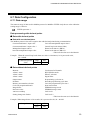
5.2.3 Selecting procedure example (Single mode)
MA900 is used in the procedure example for explanation, but the same setting procedures
also apply to MA901.
(1) When no memory area number is specified
!"Normal transmission
Host computer send
E
O 0
T
0
Address
S
T S
X
1
0
1
Identifier
0
0
Host computer send
.
0
E B
T C
X C
S
T A
X
A
C
K
Data
1
0
2
Identifier
0
0
.
Host computer send
0
E B
T C
X C
E
O
T
A
C
K
Data
Controller send
Controller send
!"Error transmission
Error data
Host computer send
E
O 0
T
0
Address
S
T S
X
Host computer send
Host computer re-send
1
0
1
Identifier
0
0
0
E B
T C
X C
S
T S
X
N
A
K
Data
1
0
1
Identifier
0
0
.
0
E B
T C
X C
E
O
T
A
C
K
Data
Controller send
Controller send
(2) When the memory area number is specified
!"Normal transmission
Host computer send
E
O 0
T
0
S
T K
X
1
S
1
0
1
Identifier
Address
0
Host computer send
0
.
0
E B
T C
X C
S
T K
X
1
A
C
K
Data
A
1
0
2
Identifier
0
0
Host computer send
.
0
E
O
T
A
C
K
Data
Memory area
number
Controller send
Memory area
number
E B
T C
X C
Controller send
!"Error transmission
Error data
Host computer send
E
O 0
T
0
Address
S
T K
X
1
S
1
Identifier
Memory area
number
IMR01H02-E3
Host computer send
Host computer re-send
0
1
0
0
Data
0
E B
T C
X C
S
T K
X
N
A
K
1
S
1
0
Identifier
Memory area number
Controller send
1
0
0
Data
.
0
E B
T C
X C
E
O
T
A
C
K
Controller send
33
5. RKC COMMUNICATION PROTOCOL
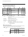
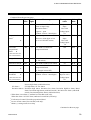
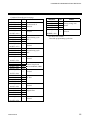
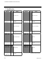
5.3 Communication Identifier List
Reference to communication identifier list
!"
(1)
(2)
(3)
Name
Identifier
No. of
digits
Model code
Measured value
(PV)
Current
transformer 1
input value
ID
M1
32
6
M2
Set value (SV) #
S1
(4)
(5)
Data range
(6)
(7)
Factory set
value
Attribute
CH
Display the model code
Within input range.
---------
RO
RO
−
×
6
CTL6P: 0.0 to 30.0 A
CTL12: 0.0 to 100.0 A
-----
RO
×
6
Within input range.
0 or 0.0
R/W
×
(1) Name:
A name of identifier is written.
The identifier whose name is marked with # indicates that corresponding to
the memory area.
(2) Identifier:
The code to identify the data is written.
(3) No. of digits:
The number of maximum digits is written.
(4) Data range:
The range of reading or writing data is written.
(5) Factory set value: The factory set value of data is written.
(6) Attribute:
The data accessing direction is written.
RO: Read only
(Data direction: Controller → Host computer)
R/W: Read and Write (Data direction: Controller ↔ Host computer)
(7) CH:
×:
Identifier with channel
−:
Identifier without channel
Data sending during polling
!"
Each time the host computer sends ACK (acknowledgement), the controller sends data corresponding
to the respective identifier in the order specified in a list of communication identifiers.
Communication is not possible when an identifier is specified that the controller can not
recognize.
Name
To be send in this order.
34
Model code
Measured value
(PV)
Current
transformer 1
Identifier
No. of
digits
Data range
ID
M1
32
6
Display the model code
Within input range.
M2
6
CTL6P: 0.0 to 30.0 A
CTL12: 0.0 to 100.0 A
IMR01H02-E3
5. RKC COMMUNICATION PROTOCOL
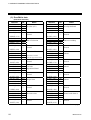
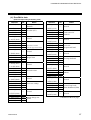
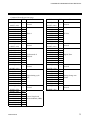
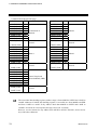
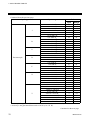
Communication identifier list
!"
Name
Identifier
No. of
digits
Model code
ID
32
Measured value
(PV)
M1
Current
transformer 1
input value
M2
Current
transformer 2
input value
M3
Data range
Factory set
value
Attribute
CH
Display the model code
-----
RO
−
6
Within input range.
-----
RO
×
6
CTL6P: 0.0 to 30.0 A
CTL12: 0.0 to 100.0 A
-----
RO
×
(This item does not
use in the MA901)
Set value monitor
MS
6
Within input range.
-----
RO
×
Burnout
B1
1
0: OFF
1: ON
-----
RO
×
Alarm 1 status
AA
1
0: OFF
1: ON
-----
RO
×
Alarm 2 status
AB
Alarm 3 status
AC
Continued on the next page.
IMR01H02-E3
35
5. RKC COMMUNICATION PROTOCOL
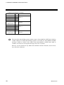
Continued form the previous page.
Name
Output status *
Identifier
No. of
digits
AJ
6
Data range
0 to 2047
Factory set
value
Attribute
CH
-----
RO
−
* The status of each output assigned to the controller is converted to the corresponding decimal data
and then is sent to the host computer. Convert the decimal data sent from the controller to the
corresponding binary data (bit image) to confirm the status.
Bit number Assignment terminal
Output type
Terminal status
b0
OUT1
b1
OUT2
b2
OUT3
Control output
b3
OUT4
or
b4
OUT5
Alarm output
b5
OUT6
0: Open 1: Close
b6
OUT7
b7
OUT8
b8
ALM1
b9
ALM2
Alarm output
b10
ALM3
In case of current output (0 to 20 mA DC, 4 to 20 mA DC), these data becomes invalid.
Example:
Bit images
(Decimal number) (Binary number)
Open/Close status
1792 =
1 1 1 0 0 0 0 0 0 0 0
Bit number
b10 b9 b8 b7 b6 b5 b4 b3 b2 b1 b0
If any defect (welding, etc.) is found in the relay located inside the instrument, the output
status may differ from the relay contact status.
Continued on the next page.
36
IMR01H02-E3
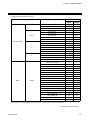
5. RKC COMMUNICATION PROTOCOL
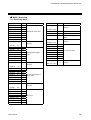
Continued form the previous page.
Name
Identifier
No. of
digits
Manipulated
output value 1
O1
6
Cool-side
manipulated
output value
O2
ER
Data range
Factory set
value
Attribute
CH
-5.0 to +105.0 %
-----
RO
×
1
0 to 5
-----
RO
−
L1
6
0 to 31
-----
RO
−
Memory area
number selection 4
ZA
1
1 to 8
1
R/W
−
Set value (SV) !
S1
6
Within input range.
0 or 0.0
R/W
×
(This item does not
use in the MA901)
Error code 2
DI status
1
2
3
3
For heat/cool control: Heat-side manipulated output value
Display the number of the error that occurred.
Example: When the adjusted data error and the A/D conversion error occur simultaneously,
the data is 2.
In addition, error contents identify error code displayed on the SV display of MA900/MA901.
Error contents: Adjusted data error, EEPROM error, A/D conversion error, Board configuration
error, Watchdog timer error
For the error contents, see the Instruction Manual (IMR01H01-E").
The RUN/STOP terminal and memory area transfer contact input (DI) terminal statuses are
converted to the corresponding decimal data, respectively and then are sent to the host computer.
Convert the decimal data sent from the controller to the corresponding binary data (bit image) to
confirm the status.
Bit number
Input type
Terminal status
b0
RUN/STOP terminal status
b1
DI1 terminal status
b2
DI2 terminal status
0: Open
1: Close
b3
DI4 terminal status
b4
DI SET terminal status
Example:
Bit images
(Decimal number) (Binary number)
Open/Close status
18 =
1 0 0 1 0
Bit number
b4 b3 b2 b1 b0
4
For selecting the memory area, a maximum time of 100 ms is required after selecting is made. If
polling is made within 100 ms after selecting is made, the data before selecting is made may be sent
to the host side depending on the timing.
Continued on the next page.
IMR01H02-E3
37
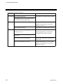
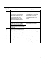
5. RKC COMMUNICATION PROTOCOL
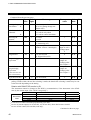
Continued from the previous page.
Name
Identifier
No. of
digits
Data range
Factory set
value
Attribute
CH
!
A1
6
Process alarm, SV alarm 1:
Same as input range
Deviation alarm 1:
-span to +span
(Within -1999 to +9999 digits)
Control loop break alarm (LBA):
0.0 to 200.0 minutes
(0.0: LBA OFF)
Temperature
input:
50 or 50.0
Voltage input:
5.0
Control loop
break alarm:
8.0
R/W 2
×
Control loop break
alarm deadband
(LBD)
!
N1
6
0 to span
However, 9999 digits or less
(0: LBD OFF)
Temperature
input: 0 or 0.0
Voltage input:
0.0
R/W 3
×
Alarm 2 4
A2
6
Process alarm, SV alarm 1:
Same as input range
Deviation alarm 1:
-span to +span
(Within -1999 to +9999 digits)
Heater break alarm 1 (HBA1):
0.0 to 100.0 A
(0.0: HBA1 OFF)
Temperature
input:
50 or 50.0
Voltage input:
5.0
R/W 5
×
R/W 6
×
Alarm 1
!
Heater break
alarm 2 (HBA2)
N2
6
0.0 to 100.0 A
(0.0: HBA2 OFF)
Heater break
alarm 1: 0.0
0.0
(This item does not
use in the MA901)
1
Process alarm =
Process high alarm, Process low alarm, Process high alarm (with hold action),
Process high alarm (with hold action)
SV alarm =
SV high alarm, SV low alarm
Deviation alarm = Deviation high alarm, Deviation low alarm, Deviation high/low alarm, Band
alarm, Deviation high alarm (with hold action), Deviation low alarm (with hold
action), Deviation high/low alarm (with hold action)
2
When the alarm 1 is FAIL alarm, attributes become RO (read only).
3
When the alarm 1 is other than the control loop break alarm (LBA), attributes become RO (read
only).
4
When the alarm 2 corresponds to heater break alarm 1 (HBA1), becomes communication data not
corresponding to the memory area.
5
When there is not alarm 2, attribute becomes RO (read only).
When the alarm 2 is FAIL alarm, attributes become RO (read only).
6
When the alarm 2 is other than heater break alarm 1 (HBA1), attributes become RO (read only).
Continued on the next page.
38
IMR01H02-E3
5. RKC COMMUNICATION PROTOCOL
Continued from the previous page.
Name
Factory set
value
Attribute
CH
Process alarm, SV alarm 1:
Same as input range
Deviation alarm 1:
-span to + span
(Within -1999 to +9999 digits)
Temperature
input:
50 or 50.0
Voltage input:
5.0
R/W 2
×
6
0 (0.0) to span
However, 9999 digits or less
(0 or 0.0: ON/OFF action)
Temperature
input:
30 or 30.0
Voltage input:
3.0
R/W
×
P2
6
1 to 1000 % of heat-side
proportional band
100
R/W 4
×
!
I1
6
0 to 3600 seconds
(0: PD action)
240
R/W
×
Derivative time !
D1
6
0 to 3600 seconds (0: PI action)
60
R/W
×
Anti-reset windup
!
W1
6
0 to 100 % of heat-side
proportional band
(0: Integral action OFF)
100
R/W
×
Overlap/
deadband
V1
6
-span to +span 5
(Within -1999 to +9999 digits)
Temperature
input: 0 or 0.0
Voltage input:
0.0
R/W 4
×
Alarm 3
!
Proportional
band 3
Identifier
No. of
digits
A3
6
P1
!
Cool-side
proportional
band
!
Data range
(This item does not
use in the MA901)
Integral time
!
(This item does not
use in the MA901)
1
Process alarm =
Process high alarm, Process low alarm, Process high alarm (with hold action),
Process high alarm (with hold action)
SV alarm =
SV high alarm, SV low alarm
Deviation alarm = Deviation high alarm, Deviation low alarm, Deviation high/low alarm, Band
alarm, Deviation high alarm (with hold action), Deviation low alarm (with hold
action), Deviation high/low alarm (with hold action)
2
When there is not alarm 3, attribute becomes RO (read only).
When the alarm 3 is FAIL alarm, attributes become RO (read only).
3
For heat/cool control: Heat-side proportional band
4
In case of heat control, become RO (read only).
5
Minus (-) setting results in overlap.
Continued on the next page.
IMR01H02-E3
39
5. RKC COMMUNICATION PROTOCOL
Continued from the previous page.
Name
Identifier
No. of
digits
Setting change
rate limiter
!
HH
6
Used/unused of
channels
EI
1
RUN/STOP
transfer 1
PID/AT selection
SR
1
G1
1
PV bias
PB
6
Digital filter
F1
6
Proportioning
cycle time 2, 3
T0
6
0 to 100 seconds
(0: Digital filter OFF)
1 to 100 seconds
Cool-side
proportioning
cycle time 3
T1
6
1 to 100 seconds
TL
6
1 to 10 seconds
!
Data range
0 (0.0) to span/min.
(0 or 0.0: Setting change rate
limiter OFF)
0: Unused
1: Used for only alarm
2: Used for control and alarm
0: STOP
1: RUN
0: PID control
1: Autotuning (AT)
-span to +span
(Within -1999 to +9999 digits)
(This item does not
Factory set
value
Attribute
CH
0
R/W
×
2
R/W
×
1
R/W
−
0
R/W
×
Temperature
input: 0 or 0.0
Voltage input:
0
0
R/W
×
R/W
×
Relay contact
output: 20
Voltage pulse/
triac output: 2
Relay contact
output: 20
Voltage pulse/
triac output: 2
R/W
×
R/W 4
×
R/W
−
use in the MA901)
Scan interval time
1
2
For changing the RUN/STOP, a maximum time of 100 ms is required after selecting is made. If
polling is made within 100 ms after selecting is made, the data before selecting is made may be sent
to the host side depending on the timing.
Relation with RUN/STOP transfer by DI
The instrument cannot be changed to the RUN by communication, if the instrument is the STOP
state by the contact input. (The “STOP” has priority.)
RUN/STOP
state
DI state
RUN
RUN
STOP
STOP
RUN/STOP transfer by communication
RUN
STOP
RUN
STOP
Instrument state
RUN
STOP
STOP
STOP
2
For heat/cool control: Heat-side proportioning cycle time
In case of current output (0 to 20 mA DC, 4 to 20 mA DC), these data becomes invalid.
4
In case of heat control, become RO (read only).
Continued on the next page.
3
40
IMR01H02-E3
5. RKC COMMUNICATION PROTOCOL
Continued from the previous page.
Name
Identifier
No. of
digits
Device address 1
IP
6
Communication
speed 1
IR
Data bit
configuration 1
Interval time 1
Data range
Factory set
value
Attribute
CH
0 to 99
0
R/W
−
6
0:
1:
2:
3:
2
R/W
−
IQ
6
See data bit configuration
table 2
0
R/W
−
IT
6
0 to 250 ms
10
R/W
−
2400 bps
4800 bps
9600 bps
19200 bps
1
The value changed becomes effective when the power is turned on again or when changed from
STOP to RUN.
2
Data bit configuration table
Set value
0
1
2
3*
4
5*
6*
7*
8*
9*
10 *
11 *
Data bit
Parity bit
Stop bit
8
8
8
8
8
8
7
7
7
7
7
7
Without
Without
Even
Even
Odd
Odd
Without
Without
Even
Even
Odd
Odd
1
2
1
2
1
2
1
2
1
2
1
2
Setting range of
Modbus
Setting range of
RKC communication
* When the Modbus communication protocol selected, this setting becomes invalid.
Continued on the next page.
IMR01H02-E3
41
5. RKC COMMUNICATION PROTOCOL
Continued from the previous page.
Name
Identifier
No. of
digits
EEPROM storage
mode 1
EB
1
Data range
0: Backup mode
(Set values are store to
the EEPROM)
Factory set
value
Attribute
CH
0
R/W
−
-----
RO
−
1: Buffer mode
(No set values are store to
the EEPROM)
EEPROM storage
status 2
1
EM
1
0: The content of the EEPROM
does not coincide with that of
the memory.
1: The content of the EEPROM
coincides with that of the
memory.
The non-volatile memory (EEPROM) has limitations on the number of memory rewrite times.
If the buffer mode is selected as an EEPROM storage mode, all of the set values changed are not
written to the EEPROM and thus a problem of limitations on the number of memory rewrite times
can be solved. When the memory is used to frequently change the set value via communication,
select the buffer mode.
When selecting any EEPROM storage mode, take notice of the following.
• If power failure occurs while the buffer mode is selected, the set value returns to the value before
the storage mode is selected.
• If the buffer mode is changed to the backup mode, all of the set values at that time are stored to
the EEPROM. If necessary to backup the final value of each set item, select the backup mode.
• When the power is turned on, the backup mode is always set.
2
The contents of the buffer memory and those of the EEPROM can be checked.
When data is 0: The contents of the buffer memory do not match with those of the EEPROM.
• As data is being written to the EEPROM in backup mode, do not turn the power
off. If turned off, no set values are stored.
• If the set value is changed after the backup mode is changed to the buffer mode,
0 is set (mismatch). As the set value changed is not backup, select the backup
mode if necessary.
When data is 1: The contents of the buffer memory match with those of the EEPROM.
(Data write to the EEPROM is completed.)
Continued on the next page.
42
IMR01H02-E3
5. RKC COMMUNICATION PROTOCOL
Continued from the previous page.
Name
Lock level 1
Lock level 2
Identifier
No. of
digits
LK
6
6
LL
Data range
Factory set
value
Attribute
CH
0000 to 1111 1
0000
R/W
−
2
0000
R/W
−
0000 to 1111
1
Selection contents of lock level 1
0: Unlock
1: Lock
0
0
0
0
Least significant digit: Items other than set value (SV) and
alarms (alarm 1 to alarm 3)
Tens digits:
Alarms (alarm 1 to alarm 3)
Hundreds digits:
SV
Most significant digit: 0 fixed
2
Selection contents of lock level 2
0: Unlock
1: Lock
0
0
0
0
Least significant digit:
Tens digits:
Hundreds digits:
Most significant digit:
IMR01H02-E3
RUN/STOP transfer
Memory area transfer
0 fixed
0 fixed
43
6. MODBUS COMMUNICATION PROTOCOL
The master controls communication between master and slave. A typical message consists of a
request (query message) sent from the master followed by an answer (response message) from the
slave. When master begins data transmission, a set of data is sent to the slave in a fixed sequence.
When it is received, the slave decodes it, takes the necessary action, and returns data to the master.
6.1 Message Format
The message consists of four parts: slave address, function code, data, and error check code which are
always transmitted in the same sequence.
Slave address
Function code
Data
Error check CRC-16
Message format
#$
Slave address
The slave address is a number from 1 to 99 manually set at the front key panel of the controller.
For details, see 4.2 Setting the Communication Parameters (P. 9).
Although all connected slaves receive the query message sent from the master, only the slave with the
slave address coinciding with the query message will accept the message.
#$
Function code
The function codes are the instructions set at the master and sent to the slave describing the action to
be executed. The function codes are included when the slave responds to the master.
For details, see 6.2 Function Code (P. 45).
#$
Data
The data to execute the function specified by the function code is sent to the slave and corresponding
data returned to the master from the slave.
For details, see 6.6 Message Format (P. 49), 6.7 Data Configuration (P. 53) and
6.8 Communication Data List (P. 55).
#$
Error check
An error checking code (CRC-16: Cyclic Redundancy Check) is used to detect an error in the signal
transmission.
For details, see 6.5 Calculating CRC-16 (P. 47).
44
IMR01H02-E3
6. MODBUS COMMUNICATION PROTOCOL
6.2 Function Code
Function code contents
Function code
(Hexadecimal)
Function
Contents
03H
Read holding registers
Measured value (PV), alarm status, etc.
06H
Preset single register
Set value (SV), alarm set value, PID constants,
PV bias, etc. (For each word)
08H
Diagnostics (loopback test)
Diagnostics (loopback test)
10H
Preset multiple registers
Set value (SV), alarm set value, PID constants,
PV bias, etc.
Message length of each function (Unit: byte)
Function code
Function
(Hexadecimal)
Query message
Response message
Min
Max
Min
Max
03H
Read holding registers
8
8
7
255
06H
Preset single register
8
8
8
8
08H
Diagnostics (loopback test)
8
8
8
8
10H
Preset multiple registers
11
255
8
8
6.3 Communication Mode
Signal transmission between the master and slaves is conducted in Remote Terminal Unit (RTU)
mode.
RTU mode
Items
Contents
Data bit length
8 bit (Binary)
Start mark of message
Unused
End mark of message
Unused
Message length
See 6.2 Function Code
Data time interval
24 bit’s time or less *
Error check
CRC-16 (Cyclic Redundancy Check)
* The data time intervals in one query message from the master must be 24 bit’s time or less. If the
data time interval exceeds 24 bit’s time, the slave regards the transmission as ended and because the
message format is incomplete, the slave does not respond.
IMR01H02-E3
45
6. MODBUS COMMUNICATION PROTOCOL
6.4 Slave Responses
(1) Normal response
• In the response message of the Read Holding Registers, the slave returns the read out data and the
number of data items with the same slave address and function code as the query message.
• In the response message of the Preset Single Resister, the slave returns the same message as the
query message.
• In the response message of the Diagnostics (loopback test), the slave returns the same message as
the query message.
• In the response message of the Preset Multiple Resister, the slave returns the slave address, the
function code, starting number and number of holding registers in the multi-query message.
(2) Defective message response
• If the query message from the master is defective, except for transmission error, the slave returns the
error response message without any action.
Slave address
Function code
Error code
Error check CRC-16
Error response message
• If the self-diagnostic function of the slave detects an error, the slave will return an error response
message to all query messages.
• The function code of each error response message is obtained by adding 80H to the function code
of the query message.
Error code
Contents
1
Function code error (Specifying nonexistent function code)
2
When any address other than 0000H to 02EEH and 1388H to 14A0H are
specified.
(However, no error returns for any address from 03E8H to 0563H. Therefore,
do not access any of the above addresses.)
46
3
When the specified number of data items in the query message exceeds the
maximum number of data items available
4
Self-diagnostic error response
IMR01H02-E3
6. MODBUS COMMUNICATION PROTOCOL
(3) No response
The slave ignores the query message and does not respond when:
• The slave address in the query message does not coincide with any slave address settings.
• The CRC code of the master does not coincide with that of the slave.
• Transmission error such as overrun, framing, parity and etc., is found in the query message.
• Data time interval in the query message from the master exceeds 24 bit’s time.
6.5 Calculating CRC-16
The Cyclic Redundancy Check (CRC) is a 2 byte (16-bit) error check code. After constructing the
data message, not including start, stop, or parity bit, the master calculates a CRC code and appends
this to the end of the message. The slave will calculate a CRC code from the received message, and
compare it with the CRC code from the master. If they do not coincide, a communication error has
occurred and the slave does not respond.
The CRC code is formed in the following sequence:
1. Load a 16-bit CRC register with FFFFH.
2. Exclusive OR (⊕) the first byte (8 bits) of the message with the CRC register. Return the result to
the CRC register.
3. Shift the CRC register 1 bit to the right.
4. If the carry flag is 1, exclusive OR the CRC register with A001 hexadecimal and return the result
to the CRC register. If the carry flag is 0, repeat step 3.
5. Repeat step 3 and 4 until there have been 8 shifts.
6. Exclusive OR the next byte (8 bits) of the message with the CRC register.
7. Repeat step 3 through 6 for all bytes of the message (except the CRC).
8. The CRC register contains the 2 byte CRC error code. When they are appended to the message,
the low-order byte is appended first, followed by the high-order byte.
IMR01H02-E3
47
6. MODBUS COMMUNICATION PROTOCOL
The flow chart of CRC-16
!"
START
FFFFH → CRC Register
CRC Register ⊕ next byte of the message →
CRC Register
0→n
Shift CRC Register right 1 bit
Carry flag is 1
No
Yes
CRC Register ⊕ A001H →
CRC Register
n+1→n
No
n>7
Yes
No
Is message
complete ?
Yes
END
The ⊕ symbol indicates an exclusive OR operation. The symbol for the number of data bits is n.
48
IMR01H02-E3
6. MODBUS COMMUNICATION PROTOCOL
6.6 Message Format
6.6.1 Read holding registers [03H]
The query message specifies the starting register address and quantity of registers to be read. The
contents of the holding registers are entered in the response message as data, divided into two parts:
the high-order 8 bits and the low-order 8 bits, arranged in the order of the register numbers.
Example: The contents of the three holding registers from 0000H to 0002H are the read out from
slave address 2.
Query message
Slave address
Function code
Starting number
Quantity
CRC-16
High
Low
High
Low
High
Low
02H
03H
00H
00H
00H
03H
05H
F8H
First holding register address
The setting must be between 1 (0001H) and
125 (007DH).
Normal response message
Slave address
Function code
Number of data
First holding
register contents
Next holding
register contents
Next holding
register contents
CRC-16
High
Low
High
Low
High
Low
High
Low
02H
03H
06H
00H
00H
00H
01H
00H
02H
E5H
84H
Number of holding registers × 2
Error response message
Slave address
80H + Function code
Error code
CRC-16
IMR01H02-E3
High
Low
02H
83H
03H
F1H
31H
49
6. MODBUS COMMUNICATION PROTOCOL
6.6.2 Preset single register [06H]
The query message specifies data to be written into the designated holding register. The write data is
arranged in the query message with high-order 8 bits first and low-order 8 bits next. Only R/W
holding registers can be specified.
Example: Data is written into the holding register 00C8H of slave address 1.
Query message
Slave address
Function code
Holding register
number
Write data
CRC-16
High
Low
High
Low
High
Low
01H
06H
00H
C8H
00H
64H
09H
DFH
Any data within the range
Normal response message
Slave address
Function code
Holding register
number
Write data
CRC-16
High
Low
High
Low
High
Low
01H
06H
00H
C8H
00H
64H
09H
DFH
Contents will be the same as query message data.
Error response message
Slave address
80H + Function code
Error code
CRC-16
50
High
Low
01H
86H
02H
C3H
A1H
IMR01H02-E3
6. MODBUS COMMUNICATION PROTOCOL
6.6.3 Diagnostics (loopback test) [08H]
The master’s query message will be returned as the response message from the slave. This function
checks the communication system between the master and slave.
Example: Loopback test for slave address 1
Query message
Slave address
Function code
Test code
Data
CRC-16
High
Low
High
Low
High
Low
01H
08H
00H
00H
1FH
34H
E9H
ECH
Test code must be set to 00.
Any pertinent data
Normal response message
Slave address
Function code
Test code
Data
CRC-16
High
Low
High
Low
High
Low
01H
08H
00H
00H
1FH
34H
E9H
ECH
Contents will be the same as query message data.
Error response message
Slave address
80H + Function code
Error code
CRC-16
IMR01H02-E3
High
Low
01H
88H
03H
06H
01H
51
6. MODBUS COMMUNICATION PROTOCOL
6.6.4 Preset multiple registers [10H]
The query message specifies the starting register address and quantity of registers to be written.
The write data is arranged in the query message with high-order 8 bits first and low-order 8 bits next.
Only R/W holding registers can be specified.
Example: Data is written into the two holding registers from 00C8H to 00C9H of slave address 1.
Query message
Slave address
Function code
Starting number
Quantity
Number of data
Data to first
register
Data to next
register
CRC-16
High
Low
High
Low
High
Low
High
Low
High
Low
01H
10H
00H
C8H
00H
02H
04H
00H
64H
00H
64H
BEH
6DH
First holding register address
The setting must be between 1 (0001H) and
100 (0064H).
Number of holding registers × 2
Any data within the range
Normal response message
Slave address
Function code
Starting number
Quantity
CRC-16
High
Low
High
Low
High
Low
01H
10H
00H
C8H
00H
02H
C0H
36H
Error response message
Slave address
80H + Function code
Error code
CRC-16
52
High
Low
01H
90H
02H
CDH
C1H
IMR01H02-E3
6. MODBUS COMMUNICATION PROTOCOL
6.7 Data Configuration
6.7.1 Data range
The numeric range of data used in Modbus protocol is 0000H to FFFFH. Only the set value within the
setting range is effective.
FFFFH represents -1.
Data processing with decimal points
Data with decimal points
!"
#"Data with one decimal place
The Modbus protocol does not recognize data with decimal points during communication.
Current transformer 1 input value
Cool-side manipulated output value *
Current transformer 2 input value *
Control loop break alarm (LBA)
Manipulated output value or
Heater break alarm 1 (HBA1)
heat-side manipulated output value
Heater break alarm 2 (HBA2) *
* This item does not use in the MA901.
Example: When the control loop break alarm set value is 8.0 minutes; 8.0 is processed as 80,
80 = 0050H
Control loop break
High
00H
alarm
Low
50H
Data without decimal points
!"
Burnout
Alarm 1 status
Alarm 2 status
Alarm 3 status
Output status
DI status
Memory area number selection
Cool-side proportional band *
Integral time
Derivative time
Anti-reset windup
Setting change rate limiter
Used/unused of channels
RUN/STOP transfer
PID/AT selection
Digital filter
Proportioning cycle time or
heat-side proportioning cycle time
Cool-side proportional cycle time *
Scan interval time
EEPROM storage mode
EEPROM storage status
Lock level 1
Lock level 2
* This item does not use in the MA901.
Example: When integral time is 50 seconds; 50 is processed as 50, 50 = 0032H
Integral time
IMR01H02-E3
High
Low
00H
32H
53
6. MODBUS COMMUNICATION PROTOCOL
Data whose decimal point’s presence and/or position depends on input range
!"
The position of the decimal point changes depending on the input range type because the Modbus
protocol does not recognize data with decimal points during communication.
The following data can have one of three decimal point positions:
• No decimal point
• One decimal place
• Two decimal place
For details, see 7. INPUT RANGE TABLES (P. 75).
Measured value (PV)
Set value monitor
Set value (SV)
Alarm 1 (Except the control loop break alarm)
Control loop break alarm (LBA)
Alarm 2 (Except the heater break alarm 1)
Alarm 3
Proportional band or heat-side proportional band
Overlap/deadband *
PV bias
* This item does not use in the MA901.
Example:
When the temperature set value is -20.0 °C; -20.0 is processed as -200,
-200 = 0000H - 00C8H = FF38H
Set value (SV)
High
FFH
Low
38H
6.7.2 Data processing precautions
• Addresses in which data (holding register) is accessible are from 0000H to 02EEH and from 1388H
to 14A0H. If any address other than 0000H to 02EEH and 1388H to 14A0H is accessed, an error
response message returns. However, no error returns for any address from 03E8H to 0563H.
Therefore, do not access any of the above addresses.
• Read data of unused channel is 0.
• Any attempt to write to an unused channel is not processed as an error. Data can not be written into
an unused channel.
• If data range or address error occurs during data writing, the data written before error is in effect.
• Communication data includes data which becomes RO (read only) depending on the specification.
No error occurs even if data is written when set to RO. However in this case, no data is written.
For details, see 6.8 Communication Data List (P. 55).
• Send the next command message at time intervals of 30 bits after the master receives the response
message.
54
IMR01H02-E3
6. MODBUS COMMUNICATION PROTOCOL
6.8 Communication Data List
The communication data list summarizes names, descriptions, factory set values and attributes.
Attribute (RO: Read only, R/W: Read and Write)
The communication data whose name is marked with ! indicates that corresponding to the
memory area.
In case of Modbus communication, data are treated as binary data in communication.
Name
Data range
Factory set value
Attribute
Measured value (PV)
Within input range.
-----
RO
Manipulated output
value 1
-5.0 to +105.0 %
-----
RO
CTL6P: 0.0 to 30.0 A
CTL12: 0.0 to 100.0 A
-----
RO
0 to 135
-----
RO
Cool-side manipulated
output value
(This item does not use in
the MA901.)
Current transformer 1
input value
Current transformer 2
input value
(This item does not use in
the MA901.)
STATUS 2
1
2
For heat/cool PID control: Heat-side manipulated output value
The alarms and burnout statuses are converted to the corresponding decimal data, respectively and
then are sent to the host computer. Convert the decimal data sent from the controller to the
corresponding binary data (bit image) to confirm the status.
Bit number
b0
b1
b2
b3 to b6
b7
b8 to b15
Details
Alarm 1 status
Alarm 2 status
Burnout status
Unused
Alarm 3 status
Unused
Alarm status
0: OFF
1: ON
Example:
Bit images
OFF/ON status
Bit number
(Decimal number)
135 =
(Binary number)
0
0
0
0
0
0
0
0
1
0
0
0
0
1
1
1
b15
b14
b13
b12
b11
b10
b9
b8
b7
b6
b5
b4
b3
b2
b1
b0
If any defect (welding, etc.) is found in the relay located inside the instrument, the output
status may differ from the relay contact status.
Continued on the next page.
IMR01H02-E3
55
6. MODBUS COMMUNICATION PROTOCOL
Continued form the previous page.
Name
Data range
Factory set
value
Attribute
Output status 1
0 to 2047
-----
RO
DI status 2
0 to 31
-----
RO
1
The status of each output assigned to the controller is converted to the corresponding decimal data
and then is sent to the host computer. Convert the decimal data sent from the controller to the
corresponding binary data (bit image) to confirm the status.
Bit number
Assignment terminal
Output type
Terminal status
b0
OUT1
b1
OUT2
b2
OUT3
Control output
b3
OUT4
or
b4
OUT5
Alarm output
b5
OUT6
0: Open 1: Close
b6
OUT7
b7
OUT8
b8
ALM1
b9
ALM2
Alarm output
b10
ALM3
In case of current output (0 to 20 mA DC, 4 to 20 mA DC), these data becomes invalid.
Example:
Bit images
(Decimal number) (Binary number)
Open/Close status
1792 =
1 1 1 0 0 0 0 0 0 0 0
Bit number
b10 b9 b8 b7 b6 b5 b4 b3 b2 b1 b0
If any defect (welding, etc.) is found in the relay located inside the instrument, the output
status may differ from the relay contact status.
2
The RUN/STOP terminal and memory area transfer contact input (DI) terminal statuses are
converted to the corresponding decimal data, respectively and then are sent to the host computer.
Convert the decimal data sent from the controller to the corresponding binary data (bit image) to
confirm the status.
Bit number
Input type
Terminal status
b0
RUN/STOP terminal status
b1
DI1 terminal status
b2
DI2 terminal status
0: Open
1: Close
b3
DI4 terminal status
b4
DI SET terminal status
Example:
Bit images
(Decimal number) (Binary number)
Open/Close status
18 =
1 0 0 1 0
Bit number
b4 b3 b2 b1 b0
Continued on the next page.
56
IMR01H02-E3
6. MODBUS COMMUNICATION PROTOCOL
Continued form the previous page.
Name
EEPROM storage
status 1
Data range
Factory set
value
Attribute
0: The content of the EEPROM does not
coincide with that of the memory.
-----
RO
Within input range.
-----
RO
Within input range.
0 or 0.0
R/W
0
R/W
Temperature input:
30 or 30.0
Voltage input: 3.0
R/W
1 to 1000 % of heat-side proportional band
100
R/W 3
1: The content of the EEPROM coincides
with that of the memory.
Set value monitor
!
Set value (SV)
PID/AT selection
Proportional band
0: PID control
2
!
Cool-side
proportional band !
1: Autotuning (AT)
0 (0.0) to span
However, 9999 digits or less
(0 or 0.0: ON/OFF action)
(This item does not use
in the MA901.)
Integral time
!
0 to 3600 seconds (0: PD action)
240
R/W
Derivative time
!
0 to 3600 seconds (0: PI action)
60
R/W
-span to +span 4
(Within -1999 to +9999 digits)
Temperature input:
0 or 0.0
Voltage input: 0.0
R/W 3
100
R/W
Overlap/deadband !
(This item does not use
in the MA901.)
Anti-reset windup !
1
0 to 100 % of heat-side proportional band
(0: Integral action OFF)
The contents of the buffer memory and those of the EEPROM can be checked.
When data is 0: The contents of the buffer memory do not match with those of the EEPROM.
• As data is being written to the EEPROM in backup mode, do not turn the power
off. If turned off, no set values are stored.
• If the set value is changed after the backup mode is changed to the buffer mode,
0 is set (mismatch). As the set value changed is not backup, select the backup
mode if necessary.
When data is 1: The contents of the buffer memory match with those of the EEPROM.
(Data write to the EEPROM is completed.)
2
For heat/cool control: Heat-side proportional band
3
In case of heat control, become RO (read only).
4
Minus (-) setting results in overlap.
Continued on the next page.
IMR01H02-E3
57
6. MODBUS COMMUNICATION PROTOCOL
Continued form the previous page.
Name
Alarm 1
Data range
!
Alarm 2 3
Alarm 3
!
Heater break alarm 2
(HBA2)
Factory set
value
Attribute
Process alarm, SV alarm 1:
Same as input range
Deviation alarm 1: -span to +span
(Within -1999 to +9999 digits)
Temperature input:
50 or 50.0
Voltage input: 5.0
R/W 2
Control loop break alarm (LBA):
0.0 to 200.0 minutes (0.0: LBA OFF)
Control loop break
alarm: 8.0
Process alarm, SV alarm 1:
Same as input range
Deviation alarm 1: -span to +span
(Within -1999 to +9999 digits)
Heater break alarm 1 (HBA1):
0.0 to 100.0 A (0.0: HBA1 OFF)
Temperature input:
50 or 50.0
Voltage input: 5.0
Process alarm, SV alarm 1:
Same as input range
Deviation alarm 1: -span to +span
(Within -1999 to +9999 digits)
0.0 to 100.0 A
(0.0: HBA2 OFF)
R/W 4
Heater break alarm 1:
0.0
Temperature input:
50 or 50.0
Voltage input: 5.0
R/W 5
0.0
R/W 6
2
R/W
(This item does not use
in the MA901.)
Used/unused of
channels
1
!
0: Unused
1: Used for only alarm
2: Used for control and alarm
Process high alarm, Process low alarm, Process high alarm (with hold action),
Process high alarm (with hold action)
SV alarm =
SV high alarm, SV low alarm
Deviation alarm = Deviation high alarm, Deviation low alarm, Deviation high/low alarm, Band
alarm, Deviation high alarm (with hold action), Deviation low alarm (with hold
action), Deviation high/low alarm (with hold action)
2
When the alarm 1 is FAIL alarm, attributes become RO (read only).
3
When the alarm 2 corresponds to heater break alarm 1 (HBA1), becomes communication data not
corresponding to the memory area.
4
When there is not alarm 2, attributes becomes RO (read only).
When the alarm 2 is FAIL alarm, attributes become RO (read only).
5
When there is not alarm 3, attribute becomes RO (read only).
When the alarm 3 is FAIL alarm, attributes become RO (read only).
6
When the alarm 2 is other than heater break alarm 1 (HBA1), attributes become RO (read only).
Continued on the next page.
58
Process alarm =
IMR01H02-E3
6. MODBUS COMMUNICATION PROTOCOL
Continued form the previous page.
Name
Data range
Proportioning cycle
time 1, 2
1 to 100 seconds
Cool-side
proportioning cycle
time 2
1 to 100 seconds
(This item does not use
Factory set
value
Attribute
Relay contact output:
20
Voltage pulse/
triac output: 2
Relay contact output:
20
Voltage pulse/
triac output: 2
R/W
R/W 3
in the MA901.)
Control loop break
alarm deadband (LBD)
!
0 to span
However, 9999 digits or less
(0: LBD OFF)
PV bias
-span to +span
(Within -1999 to +9999 digits)
Digital filter
Setting change rate
limiter
!
RUN/STOP transfer 5
Memory area number
selection
Scan interval time
Device address 6
(Slave address)
Communication speed 6
0 to 100 seconds (0: Digital filter OFF)
0 (0.0) to span/min.
(0 or 0.0: Setting change rate limiter OFF)
0: STOP
1: RUN
1 to 8
Temperature input:
0 or 0.0
Voltage input: 0.0
Temperature input:
0 or 0.0
Voltage input: 0
0
0
R/W 4
1
1
R/W
R/W
2
0
R/W
R/W
2
R/W
1 to 10 seconds
0 to 99
0: 2400 bps
1: 4800 bps
2: 9600 bps
3: 19200 bps
R/W
R/W
R/W
1
For heat/cool control: Heat-side proportioning cycle time
In case of current output (0 to 20 mA DC, 4 to 20 mA DC), these data becomes invalid.
3
In case of heat control, become RO (read only).
4
Become RO (read only) when the alarm 1 is other than control loop break alarm (LBA).
5
Relation with RUN/STOP transfer by DI
The instrument cannot be changed to the “RUN” by communication, if the instrument is the STOP
state by the contact input. (The “STOP” has priority.)
2
RUN/STOP
state
6
DI state
RUN
RUN
STOP
STOP
RUN/STOP transfer by communication
RUN
STOP
RUN
STOP
Instrument state
RUN
STOP
STOP
STOP
The value changed becomes effective when the power is turned on again or when changed from
STOP to RUN.
Continued on the next page.
IMR01H02-E3
59
6. MODBUS COMMUNICATION PROTOCOL
Continued from the previous page.
Name
Data range
Factory set
value
Attribute
0
R/W
0 to 250 ms
10
R/W
0: Backup mode
(Set values are store to the EEPROM)
0
R/W
Data bit configuration 1 See data bit configuration table 2
Interval time
1
EEPROM storage
mode 3
1: Buffer mode
(No set values are store to the EEPROM)
1
The value changed becomes effective when the power is turned on again or when changed from
STOP to RUN.
2
Data bit configuration table
Set value
0
1
2
3*
4
5*
6*
7*
8*
9*
10 *
11 *
Data bit
Parity bit
Stop bit
8
8
8
8
8
8
7
7
7
7
7
7
Without
Without
Even
Even
Odd
Odd
Without
Without
Even
Even
Odd
Odd
1
2
1
2
1
2
1
2
1
2
1
2
Setting range of
Modbus
Setting range of
RKC communication
* When the Modbus communication protocol selected, this setting becomes invalid.
3
The non-volatile memory (EEPROM) has limitations on the number of memory rewrite times.
If the buffer mode is selected as an EEPROM storage mode, all of the set values changed are not
written to the EEPROM and thus a problem of limitations on the number of memory rewrite times
can be solved. When the memory is used to frequently change the set value via communication,
select the buffer mode.
When selecting any EEPROM storage mode, take notice of the following.
• If power failure occurs while the buffer mode is selected, the set value returns to the value before
the storage mode is selected.
• If the buffer mode is changed to the backup mode, all of the set values at that time are stored to
the EEPROM. If necessary to backup the final value of each set item, select the backup mode.
• When the power is turned on, the backup mode is always set.
Continued on the next page.
60
IMR01H02-E3
6. MODBUS COMMUNICATION PROTOCOL
Continued from the previous page.
Name
Data range
Factory set
value
Attribute
Lock level 1
0000 to 1111 1
0000
R/W
Lock level 2
2
0000
R/W
0000 to 1111
1
Selection contents of lock level 1
0: Unlock
1: Lock
0
0
0
0
Least significant digit: Items other than set value (SV) and
alarms (alarm 1 to alarm 3)
Tens digits:
Alarms (alarm 1 to alarm 3)
Hundreds digits:
SV
Most significant digit: 0 fixed
2
Selection contents of lock level 2
0: Unlock
1: Lock
0
0
0
0
Least significant digit:
Tens digits:
Hundreds digits:
Most significant digit:
IMR01H02-E3
RUN/STOP transfer
Memory area transfer
0 fixed
0 fixed
61
6. MODBUS COMMUNICATION PROTOCOL
6.9 Data Map
6.9.1 Reference to data map
This data map summarizes the data addresses, channels and names that can be used with Modbus
protocol. For details on each data range, see 6.8 Communication Data List (P. 55).
(1)
(2)
(3)
Address
CH
Name
0000H (
0001H (
0002H (
0003H (
0004H (
⋅⋅
⋅
0013H (
0014H (
0015H (
0016H (
0017H (
62
0)
1)
2)
3)
4)
19)
20)
21)
22)
23)
CH1
CH2 Measured value (PV)
CH3
CH4
Unused
CH1
CH2 Manipulated output
CH3 value *
CH4
(1) Address:
Data addresses are written in hexadecimal numbers.
Characters in ( ) are decimal numbers.
(2) CH:
The channel number of controller
(3) Name:
Data names
IMR01H02-E3
6. MODBUS COMMUNICATION PROTOCOL
6.9.2 Data map list
MA900 data map
!"
(1) Read only data
Address
CH
0000H ( 0)
0001H (
1)
0002H ( 2)
0003H ( 3)
0004H (
4)
⋅⋅
⋅
0013H ( 19)
0014H ( 20)
0015H ( 21)
0016H ( 22)
0017H ( 23)
0018H ( 24)
⋅⋅
⋅
0027H ( 39)
0028H ( 40)
0029H ( 41)
002AH ( 42)
002BH ( 43)
002CH ( 44)
⋅⋅
⋅
003BH ( 59)
003CH ( 60)
003DH ( 61)
003EH ( 62)
003FH ( 63)
0040H ( 64)
0041H ( 65)
0042H ( 66)
0043H ( 67)
0044H ( 68)
⋅⋅
⋅
0063H ( 99)
0064H ( 100)
0065H ( 101)
0066H ( 102)
0067H ( 103)
0068H ( 104)
⋅⋅
⋅
0078H ( 120)
CH1
CH2
CH3
CH4
IMR01H02-E3
CH1
CH2
CH3
CH4
CH1
CH2
CH3
CH4
CH1
CH2
CH3
CH4
CH1
CH2
CH3
CH4
CH1
CH2
CH3
CH4
Name
Measured value (PV)
Unused
Manipulated output
value *
Unused
Cool-side manipulated
output value
Address
CH
0079H ( 121)
007AH ( 122)
007BH ( 123)
Name
Output status
DI status
EEPROM storage
status
007CH ( 124)
⋅⋅
Unused
⋅
008BH ( 139)
008CH ( 140) CH1
008DH ( 141) CH2 Set value monitor
008EH ( 142) CH3
008FH ( 143) CH4
0090H ( 144)
⋅⋅
Unused
⋅
00C7H ( 199)
* For heat/cool control:
Heat-side manipulated output value.
Unused
Current transformer 1
input value
Current transformer 2
input value
Unused
STATUS
Unused
63
6. MODBUS COMMUNICATION PROTOCOL
(2) Read/Write data
(Data with channels)
Address
CH
00C8H ( 200)
00C9H ( 201)
00CAH ( 202)
00CBH ( 203)
00CCH ( 204)
⋅⋅
⋅
00DBH ( 219)
00DCH ( 220)
00DDH ( 221)
00DEH ( 222)
00DFH ( 223)
00E0H ( 224)
⋅⋅
⋅
00EFH ( 239)
00F0H ( 240)
00F1H ( 241)
00F2H ( 242)
00F3H ( 243)
00F4H ( 244)
⋅⋅
⋅
0103H ( 259)
0104H ( 260)
0105H ( 261)
0106H ( 262)
0107H ( 263)
0108H ( 264)
⋅⋅
⋅
0117H ( 279)
0118H ( 280)
0119H ( 281)
011AH ( 282)
011BH ( 283)
011CH ( 284)
⋅⋅
⋅
012BH ( 299)
012CH ( 300)
012DH ( 301)
012EH ( 302)
012FH ( 303)
0130H ( 304)
⋅⋅
⋅
013FH ( 319)
CH1
CH2
CH3
CH4
CH1
CH2
CH3
CH4
CH1
CH2
CH3
CH4
CH1
CH2
CH3
CH4
CH1
CH2
CH3
CH4
CH1
CH2
CH3
CH4
Name
Set value (SV)
Unused
PID/AT selection
Unused
Proportional band
For heat/cool control:
Heat-side proportional band
Unused
Cool-side
proportional band
Unused
Integral time
Unused
Derivative time
Unused
Address
CH
0140H ( 320)
0141H ( 321)
0142H ( 322)
0143H ( 323)
0144H ( 324)
⋅⋅
⋅
0153H ( 339)
0154H ( 340)
0155H ( 341)
0156H ( 342)
0157H ( 343)
0158H ( 344)
⋅⋅
⋅
0167H ( 359)
0168H ( 360)
0169H ( 361)
016AH ( 362)
016BH ( 363)
016CH ( 364)
⋅⋅
⋅
017BH ( 379)
017CH ( 380)
017DH ( 381)
017EH ( 382)
017FH ( 383)
0180H ( 384)
⋅⋅
⋅
018FH ( 399)
0190H ( 400)
0191H ( 401)
0192H ( 402)
0193H ( 403)
0194H ( 404)
⋅⋅
⋅
01A3H ( 419)
01A4H ( 420)
01A5H ( 421)
01A6H ( 422)
01A7H ( 423)
01A8H ( 424)
⋅⋅
⋅
01B7H ( 439)
CH1
CH2
CH3
CH4
CH1
CH2
CH3
CH4
CH1
CH2
CH3
CH4
CH1
CH2
CH3
CH4
CH1
CH2
CH3
CH4
CH1
CH2
CH3
CH4
Name
Overlap/deadband
Unused
Anti-reset windup
Unused
Alarm 1
Unused
Alarm 2
Unused
Alarm 3
Unused
Heater break alarm 2
Unused
Continued on the next page.
64
IMR01H02-E3
6. MODBUS COMMUNICATION PROTOCOL
Continued form the previous page.
Address
CH
01B8H ( 440)
01B9H ( 441)
01BAH ( 442)
01BBH ( 443)
01BCH ( 444)
⋅⋅
⋅
01CBH ( 459)
01CCH ( 460)
01CDH ( 461)
01CEH ( 462)
01CFH ( 463)
01D0H ( 464)
⋅⋅
⋅
01DFH ( 479)
01E0H ( 480)
01E1H ( 481)
01E2H ( 482)
01E3H ( 483)
01E4H ( 484)
⋅⋅
⋅
0243H ( 579)
0244H ( 580)
0245H ( 581)
0246H ( 582)
0247H ( 583)
0248H ( 584)
⋅⋅
⋅
0257H ( 599)
0258H ( 600)
0259H ( 601)
025AH ( 602)
025BH ( 603)
025CH ( 604)
⋅⋅
⋅
0293H ( 659)
0294H ( 660)
0295H ( 661)
0296H ( 662)
0297H ( 663)
0298H ( 664)
⋅⋅
⋅
02A7H ( 679)
CH1
CH2
CH3
CH4
IMR01H02-E3
CH1
CH2
CH3
CH4
CH1
CH2
CH3
CH4
CH1
CH2
CH3
CH4
CH1
CH2
CH3
CH4
CH1
CH2
CH3
CH4
Name
Used/unused of
channels
Unused
Proportioning cycle
time *
Address
CH
02A8H ( 680)
02A9H ( 681)
02AAH ( 682)
02ABH ( 683)
02ACH ( 684)
⋅⋅
⋅
02BBH ( 699)
CH1
CH2
CH3
CH4
Name
Setting change rate
limiter
Unused
* For heat/cool control:
Heat-side proportioning cycle time
Unused
Cool-side
proportioning cycle
time
Unused
Control loop break
alarm deadband (LBD)
Unused
PV bias
Unused
Digital filter
Unused
65
6. MODBUS COMMUNICATION PROTOCOL
(3) Read/Write data
(Data without channel)
Address
CH
02BCH ( 700)
02BDH ( 701)
RUN/STOP transfer
Memory area number
selection
Unused
Scan interval time
Device address
Communication speed
Data bit configuration
Interval time
EEPROM storage
mode
Lock level 1
Lock level 2
Unused
02BEH ( 702)
⋅⋅
⋅
02CFH ( 719)
02D0H ( 720)
02D1H ( 721)
02D2H ( 722)
02D3H ( 723)
02D4H ( 724)
02D5H ( 725)
02D6H ( 726)
02D7H ( 727)
02D8H ( 728)
⋅⋅
⋅
02EEH ( 750)
66
Name
IMR01H02-E3
6. MODBUS COMMUNICATION PROTOCOL
(4) Read/Write data
(Data corresponding to memory area)
Address
CH
1388H (5000)
1389H (5001)
138AH (5002)
138BH (5003)
138CH (5004)
138DH (5005)
⋅⋅
⋅
139CH (5020)
139DH (5021)
139EH (5022)
139FH (5023)
13A0H (5024)
13A1H (5025)
⋅⋅
⋅
13B0H (5040)
13B1H (5041)
13B2H (5042)
13B3H (5043)
13B4H (5044)
13B5H (5045)
⋅⋅
⋅
13C4H (5060)
13C5H (5061)
13C6H (5062)
13C7H (5063)
13C8H (5064)
13C9H (5065)
⋅⋅
⋅
13D8H (5080)
13D9H (5081)
13DAH (5082)
13DBH (5083)
13DCH (5084)
13DDH (5085)
⋅⋅
⋅
13ECH (5100)
13EDH (5101)
13EEH (5102)
13EFH (5103)
13F0H (5104)
IMR01H02-E3
CH1
CH2
CH3
CH4
CH1
CH2
CH3
CH4
CH1
CH2
CH3
CH4
CH1
CH2
CH3
CH4
CH1
CH2
CH3
CH4
CH1
CH2
CH3
CH4
Name
Memory area number
selection
Set value (SV)
Unused
Proportional band
For heat/cool control:
Heat-side proportional band
Unused
Integral time
Unused
Derivative time
Unused
Anti-reset windup
Unused
Setting change rate
limiter
Address
13F1H (5105)
⋅⋅
⋅
1400H (5120)
1401H (5121)
1402H (5122)
1403H (5123)
1404H (5124)
1405H (5125)
⋅⋅
⋅
1414H (5140)
1415H (5141)
1416H (5142)
1417H (5143)
1418H (5144)
1419H (5145)
⋅⋅
⋅
1428H (5160)
1429H (5161)
142AH (5162)
142BH (5163)
142CH (5164)
142DH (5165)
⋅⋅
⋅
143CH (5180)
143DH (5181)
143EH (5182)
143FH (5183)
1440H (5184)
1441H (5185)
⋅⋅
⋅
1450H (5200)
1451H (5201)
1452H (5202)
1453H (5203)
1454H (5204)
1455H (5205)
⋅⋅
⋅
1464H (5220)
CH
CH1
CH2
CH3
CH4
CH1
CH2
CH3
CH4
CH1
CH2
CH3
CH4
CH1
CH2
CH3
CH4
CH1
CH2
CH3
CH4
Name
Unused
Used/unused of
channels
Unused
Cool-side
proportional band
Unused
Overlap/deadband
Unused
Alarm 1
Unused
Control loop break
alarm deadband (LBD)
Unused
Continued on the next page.
67
6. MODBUS COMMUNICATION PROTOCOL
Continued form the previous page.
Address
CH
1465H (5221)
1466H (5222)
1467H (5223)
1468H (5224)
1469H (5225)
⋅⋅
⋅
148CH (5260)
148DH (5261)
148EH (5262)
148FH (5263)
1490H (5264)
1491H (5265)
⋅⋅
⋅
14A0H (5280)
CH1
CH2
CH3
CH4
CH1
CH2
CH3
CH4
Name
Alarm 2
Unused
Alarm 3
Unused
The accessible data (holding register) address range is from 0000H to 02EEH and 1388H to
14A0H. Addresses in which data (holding register) is accessible are from 0000H to 02EEH
and from 1388H to 14A0H. If any address other than 0000H to 02EEH and 1388H to
14A0H is accessed, an error response message (error code: 2) returns.
However, no error returns for any address from 03E8H to 0563H. Therefore, do not access
any of the above addresses.
68
IMR01H02-E3
6. MODBUS COMMUNICATION PROTOCOL
MA901 data map
!"
(1) Read only data
Address
CH
0000H ( 0)
0001H ( 1)
0002H ( 2)
0003H (
3)
0004H ( 4)
0005H ( 5)
0006H ( 6)
0007H ( 7)
0008H (
8)
⋅⋅
⋅
0013H ( 19)
0014H ( 20)
0015H ( 21)
0016H ( 22)
0017H ( 23)
0018H ( 24)
0019H ( 25)
001AH ( 26)
001BH ( 27)
001CH ( 28)
⋅⋅
⋅
003BH ( 59)
003CH ( 60)
003DH ( 61)
003EH ( 62)
003FH ( 63)
0040H ( 64)
0041H ( 65)
0042H ( 66)
0043H ( 67)
0044H ( 68)
⋅⋅
⋅
0063H ( 99)
0064H ( 100)
0065H ( 101)
0066H ( 102)
0067H ( 103)
0068H ( 104)
0069H ( 105)
006AH ( 106)
006BH ( 107)
CH1
CH2
CH3
CH4
CH5
CH6
CH7
CH8
IMR01H02-E3
CH1
CH2
CH3
CH4
CH5
CH6
CH7
CH8
CH1
CH2
CH3
CH4
CH5
CH6
CH7
CH8
CH1
CH2
CH3
CH4
CH5
CH6
CH7
CH8
Name
Measured value (PV)
Unused
Manipulated output
value
Unused
Address
006CH ( 108)
⋅⋅
⋅
0078H ( 120)
0079H ( 121)
007AH ( 122)
007BH ( 123)
007CH ( 124)
⋅⋅
⋅
008BH ( 139)
008CH ( 140)
008DH ( 141)
008EH ( 142)
008FH ( 143)
0090H ( 144)
0091H ( 145)
0092H ( 146)
0093H ( 147)
0094H ( 148)
⋅⋅
⋅
00C7H ( 199)
CH
Name
Unused
Output status
DI status
EEPROM storage
status
Unused
CH1
CH2
CH3
CH4
CH5
CH6
CH7
CH8
Set value monitor
Unused
Current transformer 1
input value
Unused
STATUS
69
6. MODBUS COMMUNICATION PROTOCOL
(2) Read/Write data
(Data with channels)
Address
CH
00C8H ( 200)
00C9H ( 201)
00CAH ( 202)
00CBH ( 203)
00CCH ( 204)
00CDH ( 205)
00CEH ( 206)
00CFH ( 207)
00D0H ( 208)
⋅⋅
⋅
00DBH ( 219)
00DCH ( 220)
00DDH ( 221)
00DEH ( 222)
00DFH ( 223)
00E0H ( 224)
00E1H ( 225)
00E2H ( 226)
00E3H ( 227)
00E4H ( 228)
⋅⋅
⋅
00EFH ( 239)
00F0H ( 240)
00F1H ( 241)
00F2H ( 242)
00F3H ( 243)
00F4H ( 244)
00F5H ( 245)
00F6H ( 246)
00F7H ( 247)
00F8H ( 248)
⋅⋅
⋅
0117H ( 279)
0118H ( 280)
0119H ( 281)
011AH ( 282)
011BH ( 283)
011CH ( 284)
011DH ( 285)
011EH ( 286)
011FH ( 287)
0120H ( 288)
⋅⋅
⋅
012BH ( 299)
CH1
CH2
CH3
CH4
CH5
CH6
CH7
CH8
70
CH1
CH2
CH3
CH4
CH5
CH6
CH7
CH8
CH1
CH2
CH3
CH4
CH5
CH6
CH7
CH8
CH1
CH2
CH3
CH4
CH5
CH6
CH7
CH8
Name
Set value (SV)
Unused
PID/AT selection
Unused
Proportional band
Unused
Integral time
Unused
Address
CH
012CH ( 300)
012DH ( 301)
012EH ( 302)
012FH ( 303)
0130H ( 304)
0131H ( 305)
0132H ( 306)
0133H ( 307)
0134H (308)
⋅⋅
⋅
0153H ( 339)
0154H ( 340)
0155H ( 341)
0156H ( 342)
0157H ( 343)
0158H ( 344)
0159H ( 345)
015AH ( 346)
015BH ( 347)
015CH ( 348)
⋅⋅
⋅
0167H ( 359)
0168H ( 360)
0169H ( 361)
016AH ( 362)
016BH ( 363)
016CH ( 364)
016DH ( 365)
016EH ( 366)
016FH ( 367)
0170H ( 368)
⋅⋅
⋅
017BH ( 379)
017CH ( 380)
017DH ( 381)
017EH ( 382)
017FH ( 383)
0180H ( 384)
0181H ( 385)
0182H ( 386)
0183H ( 387)
CH1
CH2
CH3
CH4
CH5
CH6
CH7
CH8
CH1
CH2
CH3
CH4
CH5
CH6
CH7
CH8
CH1
CH2
CH3
CH4
CH5
CH6
CH7
CH8
Name
Derivative time
Unused
Anti-reset windup
Unused
Alarm 1
Unused
CH1
CH2
CH3
CH4 Alarm 2
CH5
CH6
CH7
CH8
Continued on the next page.
IMR01H02-E3
6. MODBUS COMMUNICATION PROTOCOL
Continued from the previous page.
Address
0184H ( 388)
⋅⋅
⋅
018FH ( 399)
0190H ( 400)
0191H ( 401)
0192H ( 402)
0193H ( 403)
0194H ( 404)
0195H ( 405)
0196H ( 406)
0197H ( 407)
0198H ( 408)
⋅⋅
⋅
01B7H ( 439)
01B8H ( 440)
01B9H ( 441)
01BAH ( 442)
01BBH ( 443)
01BCH ( 444)
01BDH ( 445)
01BEH ( 446)
01BFH ( 447)
01C0H ( 448)
⋅⋅
⋅
01CBH ( 459)
01CCH ( 460)
01CDH ( 461)
01CEH ( 462)
01CFH ( 463)
01D0H ( 464)
01D1H ( 465)
01D2H ( 466)
01D3H ( 467)
01D4H ( 468)
⋅⋅
⋅
0243H ( 579)
0244H ( 580)
0245H ( 581)
0246H ( 582)
0247H ( 583)
0248H ( 584)
0249H ( 585)
024AH ( 586)
024BH ( 587)
IMR01H02-E3
CH
CH1
CH2
CH3
CH4
CH5
CH6
CH7
CH8
CH1
CH2
CH3
CH4
CH5
CH6
CH7
CH8
CH1
CH2
CH3
CH4
CH5
CH6
CH7
CH8
CH1
CH2
CH3
CH4
CH5
CH6
CH7
CH8
Name
Unused
Alarm 3
Unused
Used/unused of
channels
Unused
Proportioning cycle
time
Unused
Address
024CH ( 588)
⋅⋅
⋅
0257H ( 599)
0258H ( 600)
0259H ( 601)
025AH ( 602)
025BH ( 603)
025CH ( 604)
025DH ( 605)
025EH ( 606)
025FH ( 607)
0260H ( 608)
⋅⋅
⋅
0293H ( 659)
0294H ( 660)
0295H ( 661)
0296H ( 662)
0297H ( 663)
0298H ( 664)
0299H ( 665)
029AH ( 666)
029BH ( 667)
029CH ( 668)
⋅⋅
⋅
02A7H ( 679)
02A8H ( 680)
02A9H ( 681)
02AAH ( 682)
02ABH ( 683)
02ACH ( 684)
02ADH ( 685)
02AEH ( 686)
02AFH ( 687)
02B0H ( 688)
⋅⋅
⋅
02BBH ( 699)
CH
CH1
CH2
CH3
CH4
CH5
CH6
CH7
CH8
CH1
CH2
CH3
CH4
CH5
CH6
CH7
CH8
CH1
CH2
CH3
CH4
CH5
CH6
CH7
CH8
Name
Unused
PV bias
Unused
Digital filter
Unused
Setting change rate
limiter
Unused
Control loop break
alarm deadband (LBD)
71
6. MODBUS COMMUNICATION PROTOCOL
(3) Read/Write data
(Data without channel)
Address
CH
02BCH ( 700)
02BDH ( 701)
RUN/STOP transfer
Memory area number
selection
Unused
Scan interval time
Device address
Communication speed
Data bit configuration
Interval time
EEPROM storage
mode
Lock level 1
Lock level 2
Unused
02BEH ( 702)
⋅⋅
⋅
02CFH ( 719)
02D0H ( 720)
02D1H ( 721)
02D2H ( 722)
02D3H ( 723)
02D4H ( 724)
02D5H ( 725)
02D6H ( 726)
02D7H ( 727)
02D8H ( 728)
⋅⋅
⋅
02EEH ( 750)
72
Name
IMR01H02-E3
6. MODBUS COMMUNICATION PROTOCOL
(4) Read/Write data
(Data corresponding to memory area)
Address
CH
1388H (5000)
1389H (5001)
138AH (5002)
138BH (5003)
138CH (5004)
138DH (5005)
138EH (5006)
138FH (5007)
1390H (5008)
1391H (5009)
⋅⋅
⋅
139CH (5020)
139DH (5021)
139EH (5022)
139FH (5023)
13A0H (5024)
13A1H (5025)
13A2H (5026)
13A3H (5027)
13A4H (5028)
13A5H (5029)
⋅⋅
⋅
13B0H (5040)
13B1H (5041)
13B2H (5042)
13B3H (5043)
13B4H (5044)
13B5H (5045)
13B6H (5046)
13B7H (5047)
13B8H (5048)
13B9H (5049)
⋅⋅
⋅
13C4H (5060)
13B9H (5049)
⋅⋅
⋅
13C4H (5060)
CH1
CH2
CH3
CH4
CH5
CH6
CH7
CH8
IMR01H02-E3
CH1
CH2
CH3
CH4
CH5
CH6
CH7
CH8
CH1
CH2
CH3
CH4
CH5
CH6
CH7
CH8
Name
Memory area number
selection
Set value (SV)
Unused
Proportional band
Unused
Integral time
Unused
Unused
Address
CH
13C5H (5061)
13C6H (5062)
13C7H (5063)
13C8H (5064)
13C9H (5065)
13CAH (5066)
13CBH (5067)
13CCH (5068)
13CDH (5069)
⋅⋅
⋅
13D8H (5080)
13D9H (5081)
13DAH (5082)
13DBH (5083)
13DCH (5084)
13DDH (5085)
13DEH (5086)
13DFH (5087)
13E0H (5088)
13E1H (5089)
⋅⋅
⋅
13ECH (5100)
13EDH (5101)
13EEH (5102)
13EFH (5103)
13F0H (5104)
13F1H (5105)
13F2H (5106)
13F3H (5107)
13F4H (5108)
13F5H (5109)
⋅⋅
⋅
1400H (5120)
CH1
CH2
CH3
CH4
CH5
CH6
CH7
CH8
CH1
CH2
CH3
CH4
CH5
CH6
CH7
CH8
CH1
CH2
CH3
CH4
CH5
CH6
CH7
CH8
Name
Derivative time
Unused
Anti-reset windup
Unused
Setting change rate
limiter
Unused
Continued on the next page.
73
6. MODBUS COMMUNICATION PROTOCOL
Continued from the previous page.
Address
CH
1401H (5121)
1402H (5122)
1403H (5123)
1404H (5124)
1405H (5125)
1406H (5126)
1407H (5127)
1408H (5128)
1409H (5129)
⋅⋅
⋅
143CH (5180)
143DH (5181)
143EH (5182)
143FH (5183)
1440H (5184)
1441H (5185)
1442H (5186)
1443H (5187)
1444H (5188)
1445H (5189)
⋅⋅
⋅
1450H (5200)
1451H (5201)
1452H (5202)
1453H (5203)
1454H (5204)
1455H (5205)
1456H (5206)
1457H (5207)
1458H (5208)
1459H (5209)
⋅⋅
⋅
1464H (5220)
CH1
CH2
CH3
CH4
CH5
CH6
CH7
CH8
CH1
CH2
CH3
CH4
CH5
CH6
CH7
CH8
CH1
CH2
CH3
CH4
CH5
CH6
CH7
CH8
Name
Used/unused of
channels
Unused
Alarm 1
Unused
Address
CH
1465H (5221)
1466H (5222)
1467H (5223)
1468H (5224)
1469H (5225)
146AH (5226)
146BH (5227)
146CH (5228)
146DH (5229)
⋅⋅
⋅
148CH (5260)
148DH (5261)
148EH (5262)
148FH (5263)
1490H (5264)
1491H (5265)
1492H (5266)
1493H (5267)
1494H (5268)
1495H (5269)
⋅⋅
⋅
14A0H (5280)
CH1
CH2
CH3
CH4
CH5
CH6
CH7
CH8
CH1
CH2
CH3
CH4
CH5
CH6
CH7
CH8
Name
Alarm 2
Unused
Alarm 3
Unused
Control loop break
alarm deadband (LBD)
Unused
The accessible data (holding register) address range is from 0000H to 02EEH and 1388H to
14A0H. Addresses in which data (holding register) is accessible are from 0000H to 02EEH
and from 1388H to 14A0H. If any address other than 0000H to 02EEH and 1388H to
14A0H is accessed, an error response message (error code: 2) returns.
However, no error returns for any address from 03E8H to 0563H. Therefore, do not access
any of the above addresses.
74
IMR01H02-E3
7. INPUT RANGE TABLES
Input Range Table 1
Input type
Input range
Code
0 to 200 °C
0 to 400 °C
0 to 600 °C
0 to 800 °C
0 to 1000 °C
0 to 1200 °C
0 to 1372 °C
-199.9 to +300.0 °C *
0.0 to 400.0 °C
0.0 to 800.0 °C
K
0 to 100 °C
0 to 300 °C
0 to 450 °C
0 to 500 °C
0.0 to 200.0 °C
0.0 to 600.0 °C
Thermocouple
-199.9 to +800.0 °C *
0 to 800 °F
0 to 1600 °F
0 to 2502 °F
0.0 to 800.0 °F
20 to 70 °F
-199.9 to +999.9 °F *
0 to 200 °C
0 to 400 °C
0 to 600 °C
0 to 800 °C
0 to 1000 °C
J
0 to 1200 °C
-199.9 to +300.0 °C *
0.0 to 400.0 °C
0.0 to 800.0 °C
0 to 450 °C
0.0 to 200.0 °C
0.0 to 600.0 °C
-199.9 to +600.0 °C *
* Accuracy is not guaranteed between -199.9 to -100.0 °C (-199.9 to -148.0 °F)
Input
Range
K
K
K
K
K
K
K
K
K
K
K
K
K
K
K
K
K
K
K
K
K
K
K
J
J
J
J
J
J
J
J
J
J
J
J
J
01
02
03
04
05
06
07
08
09
10
13
14
17
20
29
37
38
A1
A2
A3
A4
A9
B2
01
02
03
04
05
06
07
08
09
10
22
23
30
Continued on the next page.
IMR01H02-E3
75
7. INPUT RANGE TABLES
Continued from the previous page.
Input type
Input range
J
R
S
Thermocouple
B
E
N
T
1
2
76
0 to 800 °F
0 to 1600 °F
0 to 2192 °F
0 to 400 °F
-199.9 to +999.9 °F 1
0.0 to 800.0 °F
0 to 1600 °C 2
0 to 1769 °C 2
0 to 1350 °C 2
0 to 3200 °F 2
0 to 3216 °F 2
0 to 1600 °C 2
0 to 1769 °C 2
0 to 3200 °F 2
0 to 3216 °F 2
400 to 1800 °C
0 to 1820 °C 2
800 to 3200 °F
0 to 3308 °F 2
0 to 800 °C
0 to 1000 °C
0 to 1600 °F
0 to 1832 °F
0 to 1200 °C
0 to 1300 °C
0.0 to 800.0 °C
0 to 2300 °F
0 to 2372 °F
0.0 to 999.9 °F
-199.9 to +400.0 °C 1
-199.9 to +100.0 °C 1
-100.0 to +200.0 °C
0.0 to 350.0 °C
-199.9 to +752.0 °F 1
-100.0 to +200.0 °F
-100.0 to +400.0 °F
0.0 to 450.0 °F
0.0 to 752.0 °F
Code
Input
J
J
J
J
J
J
R
R
R
R
R
S
S
S
S
B
B
B
B
E
E
E
E
N
N
N
N
N
N
T
T
T
T
T
T
T
T
T
Range
A1
A2
A3
A6
A9
B6
01
02
04
A1
A2
01
02
A1
A2
01
02
A1
A2
01
02
A1
A2
01
02
06
A1
A2
A5
01
02
03
04
A1
A2
A3
A4
A5
Accuracy is not guaranteed between -199.9 to -100.0 °C (-199.9 to -148.0 °F)
Accuracy is not guaranteed between 0 to 399 °C (0 to 751 °F)
Continued on the next page.
IMR01H02-E3
7. INPUT RANGE TABLES
Continued from the previous page.
Input type
Input range
Code
0 to 2000 °C
0 to 2320 °C
0 to 4000 °F
0 to 1300 °C
0 to 1390 °C
PL II
0 to 1200 °C
0 to 2400 °F
0 to 2534 °F
Thermocouple
-199.9 to +600.0 °C *
-199.9 to +100.0 °C *
0.0 to 400.0 °C
U
-199.9 to +999.9 °F *
-100.0 to +200.0 °F
0.0 to 999.9 °F
0 to 400 °C
L
0 to 800 °C
0 to 800 °F
0 to 1600 °F
-199.9 to +649.0 °C
-199.9 to +200.0 °C
-100.0 to +50.0 °C
-100.0 to +100.0 °C
-100.0 to +200.0 °C
0.0 to 50.0 °C
0.0 to 100.0 °C
0.0 to 200.0 °C
0.0 to 300.0 °C
RTD
Pt100
0.0 to 500.0 °C
-199.9 to +999.9 °F
-199.9 to +400.0 °F
-199.9 to +200.0 °F
-100.0 to +100.0 °F
-100.0 to +300.0 °F
0.0 to 100.0 °F
0.0 to 200.0 °F
0.0 to 400.0 °F
0.0 to 500.0 °F
* Accuracy is not guaranteed between -199.9 to -100.0 °C (-199.9 to -148.0 °F)
W5Re/W26Re
Input
Range
W
W
W
A
A
A
A
A
U
U
U
U
U
U
L
L
L
L
D
D
D
D
D
D
D
D
D
D
D
D
D
D
D
D
D
D
D
01
02
A1
01
02
03
A1
A2
01
02
03
A1
A2
A3
01
02
A1
A2
01
02
03
04
05
06
07
08
09
10
A1
A2
A3
A4
A5
A6
A7
A8
A9
Continued on the next page.
IMR01H02-E3
77
7. INPUT RANGE TABLES
Continued from the previous page.
Input type
RTD
Input range
JPt100
-199.9 to +649.0 °C
-199.9 to +200.0 °C
-100.0 to +50.0 °C
-100.0 to +100.0 °C
-100.0 to +200.0 °C
0.0 to 50.0 °C
0.0 to 100.0 °C
0.0 to 200.0 °C
0.0 to 300.0 °C
0.0 to 500.0 °C
Code
Input
Range
P
P
P
P
P
P
P
P
P
P
01
02
03
04
05
06
07
08
09
10
Input Range Table 2
Input type
Voltage
78
0 to 5 V DC
0 to 10 V DC
1 to 5 V DC
Input range
0.0 to 100.0 %
Code
Input
Range
4
5
6
01
01
01
IMR01H02-E3
8. TROUBLESHOOTING
!
WARNING
To prevent electric shock or instrument failure, always turn off the system
#"
power before replacing the instrument.
To prevent electric shock or instrument failure, always turn off the power
#"
before mounting or removing the instrument.
To prevent electric shock or instrument failure, do not turn on the power until
#"
all the wiring is completed.
To prevent electric shock or instrument failure, do not touch the inside of the
#"
instrument.
All wiring must be performed by authorized personnel with electrical
#"
experience in this type of work.
CAUTION
All wiring must be completed before power is turned on to prevent electric shock, instrument
failure, or incorrect action.
The power must be turned off before repairing work for input break and output failure
including replacement of sensor, contactor or SSR, and all wiring must be completed before
power is turned on again.
This section lists some of the main causes and solutions for communication problems.
If you can not solve a problem, please contact RKC sales office or the agent, on confirming the type
name and specifications of the product.
!"
RKC communication
Problem
Probable cause
No response Wrong connection, no connection or
disconnection of the communication cable
Solution
Confirm the connection method or
condition and connect correctly
Breakage, wrong wiring, or imperfect
contact of the communication cable
Confirm the wiring or connector and
repair or replace the wrong one
Mismatch of the setting data of
communication speed and data bit
configuration with those of the host
Confirm the settings and set them
correctly
Wrong address setting
Continued on the next page.
IMR01H02-E3
79
8. TROUBLESHOOTING
Continued from the previous page.
Problem
Probable cause
No response Error in the data format
Solution
Reexamine the communication program
Transmission line is not set to the receive
state after data send (for RS-485)
EOT return The specified identifier is invalid
Error in the data format
NAK return Error occurs on the line (parity bit error,
framing error, etc.)
Confirm the identifier is correct or that
with the correct function is specified.
Otherwise correct it
Reexamine the communication program
Confirm the cause of error, and solve the
problem appropriately. (Confirm the
transmitting data, and resend data)
BCC error
80
The data exceeds the setting range
Confirm the setting range and transmit
correct data
The specified identifier is invalid
Confirm the identifier is correct or that
with the correct function is specified.
Otherwise correct it
IMR01H02-E3
8. TROUBLESHOOTING
!"
Modbus
Problem
Probable cause
No response Wrong connection , no connection or
disconnection of the communication cable
Solution
Confirm the connection method or
condition and connect correctly
Breakage, wrong wiring, or imperfect
contact of the communication cable
Confirm the wiring or connector and
repair or replace the wrong one
Mismatch of the setting data of
communication speed and data bit
configuration with those of the host
Confirm the settings and set them
correctly
Wrong address setting
A transmission error (overrun error,
framing error, parity error or CRC-16
error) is found in the query message
Re-transmit after time-out occurs or
verify communication program
The time interval between adjacent data in
the query message is too long, exceeding
24 bit’s time
Error code Function cod error
1
(Specifying nonexistent function code)
Confirm the function code
Error code When any address other than 0000H to
2
02EEH and 1388H to 14A0H are specified
(However, no error returns for any address
from 03E8H to 0563H. Therefore, do not
access any of the above addresses.)
Confirm the address of holding register
Error code When the specified number of data items
3
in the query message exceeds the
maximum number of data items available
Confirm the setting data
Error code Self-diagnostic error
4
Turn off the power to the instrument. If
the same error occurs when the power is
turned back on, please contact RKC
sales office or the agent.
IMR01H02-E3
81
9. ASCII 7-BIT CODE TABLE
This table is only for use with RKC communication.
b5 to b7
82
b7
0
0
0
0
1
1
1
1
b6
0
0
1
1
0
0
1
1
b5
0
1
0
1
0
1
0
1
0
1
2
3
4
5
6
7
b4 b3 b2 b1
0
0
0
0
0
NUL
DLE
SP
0
@
P
‘
p
0
0
0
1
1
SOH
DC1
!
1
A
Q
a
q
0
0
1
0
2
STX
DC2
”
2
B
R
b
r
0
0
1
1
3
ETX
DC3
#
3
C
S
c
s
0
1
0
0
4
EOT
DC4
$
4
D
T
d
t
0
1
0
1
5
ENQ
NAK
%
5
E
U
e
u
0
1
1
0
6
ACK
SYM
&
6
F
V
f
v
0
1
1
1
7
BEL
ETB
’
7
G
W
g
w
1
0
0
0
8
BS
CAN
(
8
H
X
h
x
1
0
0
1
9
HT
EM
)
9
I
Y
i
y
1
0
1
0
A
LF
SUB
*
:
J
Z
j
z
1
0
1
1
B
VT
ESC
+
;
K
[
k
{
1
1
0
0
C
FF
FS
,
<
L
¥
l
|
1
1
0
1
D
CR
GS
-
=
M
]
m
}
1
1
1
0
E
SO
RS
.
>
N
^
n
˜
1
1
1
1
F
SI
US
/
?
O
_
o
DEL
IMR01H02-E3
The first edition: MAY 2001
The third edition: MAR. 2002 [IMQ00]
RKC INSTRUMENT INC.
HEADQUARTERS: 16-6, KUGAHARA 5-CHOME, OHTA-KU TOKYO 146-8515 JAPAN
PHONE: 03-3751-9799 (+81 3 3751 9799)
E-mail: [email protected]
FAX:
03-3751-8585 (+81 3 3751 8585)
IMR01H02-E3
MAR. 2002