1
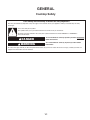
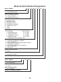
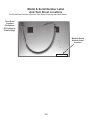
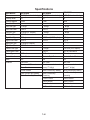
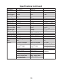
KAC-54
TECHNICAL EDUCATION
INDUCTION COOKTOP
Models:
Kitchen Aid
KICU500X
KICU509X
KICU569X
Jenn-Air
JIC4430X
JIC4536X
Whirlpool
GIC3051X
JOB AID W10346831
FORWARD
This Induction Cooktop Job Aid (W10346831), provides the In-Home Service Professional with
information on the installation, operation, and service of the Induction Cooktop. For specific information on the model being serviced, refer to the “Use and Care Guide,” or “Wiring Diagram”
provided with the cooktop.
The Wiring Diagrams used in this Job Aid are typical and should be used for training purposes
only. Always use the Wiring Diagram supplied with the product when servicing the cooktop.
GOALS AND OBJECTIVES
The goal of this Job Aid is to provide information that will enable the In-Home Service Professional
to properly diagnose malfunctions and repair the Induction Cooktop.
The objectives of this Job Aid are to:
• Understand and follow proper safety precautions.
• Successfully troubleshoot and diagnose malfunctions.
• Successfully perform necessary repairs.
• Successfully return the cooktop to its proper operational status.
WHIRLPOOL CORPORATION assumes no responsibility for any repairs made on
our products by anyone other than authorized In-Home Service Professionals.
Copyright © 2010, Whirlpool Corporation, Benton Harbor, MI 49022
- ii -
TABLE OF CONTENTS
Page
GENERAL ............................................................................................................................... 1-1
Cooktop Safety................................................................................................................... 1-1
Model & Serial Number Designations................................................................................. 1-2
Model & Serial Number Label And Tech Sheet Locations................................................... 1-3
Specifications...................................................................................................................... 1-4
Induction Cooktop Components.......................................................................................... 1-6
INSTALLATION INFORMATION ............................................................................................ 2-1
Installation Instructions....................................................................................................... 2-1
PRODUCT OPERATION ....................................................................................................... 3-1
Theory of Induction Cooking............................................................................................... 3-1
Advantages Of Induction Cooking...................................................................................... 3-3
Faster Cycle Time............................................................................................................... 3-2
High Thermal Efficiency And Increased Profitability............................................................ 3-2
Cool Stove Top.................................................................................................................... 3-3
Environmentally Sound....................................................................................................... 3-3
User-Friendly....................................................................................................................... 3-4
Pinpoint Accuracy............................................................................................................... 3-4
Maximum Repeatability....................................................................................................... 3-4
Noises that are Common to the Normal Operation of Induction Cooktops......................... 3-4
Overview of Induction Cookware........................................................................................ 3-5
Pots and Pans good for Induction Cooking......................................................................... 3-5
Pots and Pans not good for Induction Cooking................................................................... 3-5
COMPONENT ACCESS ......................................................................................................... 4-1
Component Locations......................................................................................................... 4-1
Removing The Cooktop Glass............................................................................................ 4-2
Removing the User Interface.............................................................................................. 4-3
Removing An Induction Element......................................................................................... 4-4
Removing a Cooling Fan.................................................................................................... 4-5
Removing, Power Control Board, Fuses and EMI Board.................................................... 4-6
Terminal Block, Capacitor, Shunt Clip and Thermofuses.................................................... 4-7
COMPONENT TESTING ........................................................................................................ 5-1
Component Testing Chart................................................................................................... 5-2
Coil Burner.......................................................................................................................... 5-3
Coil Sensor (S1).................................................................................................................. 5-3
Strip Circuit.......................................................................................................................... 5-4
TROUBLESHOOTING ............................................................................................................ 6-1
Failure/Effor Codes............................................................................................................. 6-2
Type 1................................................................................................................................. 6-3
Type 2................................................................................................................................. 6-3
Type 3................................................................................................................................. 6-3
Control Board Indicator Light.............................................................................................. 6-7
WIRING DIAGRAM ................................................................................................................ 7-1
30˝ Cooktop......................................................................................................................... 7-1
- iii -
— NOTES —
- iv -
GENERAL
Cooktop Safety
Your safety and the safety of others are very important.
We have provided many important safety messages in this manual and on your appliance. Always read and obey all safety
messages.
This is the safety alert symbol.
This symbol alerts you to potential hazards that can kill or hurt you and others.
All safety messages will follow the safety alert symbol and either the word “DANGER” or “WARNING.”
These words mean:
DANGER
WARNING
You can be killed or seriously injured if you don't immediately
follow instructions.
You can be killed or seriously injured if you don't follow
instructions.
All safety messages will tell you what the potential hazard is, tell you how to reduce the chance of injury, and tell you what can
happen if the instructions are not followed.
1-1
Model & Serial Number Designations
MODEL NUMBER K
IC
U
50
9
X
SS
PRODUCT GROUP
K = KITCHENAID BRAND
PRODUCT IDENTIFICATION
EC = ELECTRIC COOKTOP
GC = GAS COOKTOP
IC = INDUCTION COOKTOP
MERCHANDISING SCHEME
C = CERAMIC GLASS
C = ARCHITECT (GAS)
D = DOWNDRAFT VENT
K = STANDARD KITCHENAID
P = COMMERCIAL STYLE
S = (GAS)
U
= ULTIMA
CAPACITY / SIZE / SERIES / CONFIGURATION
1ST POSITION
2ND POSITION
0 = TEMPERED GLASS 0 = 30˝ WIDE
1 = STAINLESS STEEL 5 = 15˝ WIDE
4 = COMMERCIAL STYLE 6 = 36˝ WIDE
5 = CERAMIC GLASS 8 = 48˝ WIDE
7 = STAINLESS STEEL W/CLEAR COAT
FEATURE CODE
0 = STANDARD ELEMENTS / BURNERS
1 = RADIANT ELEMENTS
2 = DUAL ELEMENTS OR SEALED BURNERS W/GRILL
6 = 5 BURNERS / ELEMENTS
7 = HALOGEN ELEMENTS / OR 6 BURNERS
8 = TOUCH CONTROLS
9 = INDUCTION
YEAR OF INTRODUCTION
X = 2010
COLOR CODE
SS= STAINLESS STEEL
ENGINEERING CHANGE (0, 1, 2, ETC.)
SERIAL NUMBER
DP
DIVISION RESPONSIBILITY
DP = CLEVELAND
YEAR OF PRODUCTION
0 = 2010
WEEK OF PRODUCTION
24 = 24TH WEEK
PRODUCT SEQUENCE NUMBER
0 24
01234
1-2
0
Model & Serial Number Label
And Tech Sheet Locations
The Model/Serial Number label and Tech Sheet locations are shown below.
Tech Sheet
Location
(On Bottom
Of Cooktop In
Plastic Bag))
Model & Serial
Number Label
Location
1-3
Specifications
New Model
Color
Cooktop Width
Cooktop Material
Number of Elements
Left Front Type
Left Front Power
Left Rear Type
Left Rear Power
Right Front Type
Right Front Power
Right Rear Type
Right Rear Power
Central Front Type
Central Rear Power
Control Type
Control Location
Knob
Features
KICU500X
BL/SS (BL has beveled edge)
30"
Ceran
4
6" Single
1800 W
9" Single (10" Graphic)
3200 W
7" Single
2500 W
8" Single (9" Graphic)
3000 W
KICU509X
BL/SS (BL has beveled edge)
30"
Ceran
4
7" Bridge
2500 W
7" Bridge
KICU569X
BL/SS (BL has beveled edge)
36"
Ceran
5
7" Bridge
2500 W
7" Bridge
10/8" Dual (11/9" Graphic)
3700 W
7" Bridge
2500 W
7" Bridge
6" Single
1800 W
G8 Touch
G8 Touch
Center Front
Cluster in Right Front
N/A
N/A
One Timer
One Timer
Booster on All Elements
Boosters on each element
Pause Function
(except 7" bridge)
Control Lockout
Quick Function Key: Melting
Quick Function Key: Melting
Quick Function Key:
Quick Function Key: Simmering Simmering
Control Lockout
Pause Function
Control Lockout
All. Extruded frame
1-4
11/8" Dual (12/9" Graphic)
5000 W Power Boost
G8 touch
Cluster in Central Front
N/A
One Timer
Boosters on each element
(except 7" bridge)
Quick Function Key: Melting
Quick Function Key:
Simmering
Control Lockout
Pause Function
Control Lockout
All. Extruded frame
Specifications (continued)
New Model
Color
Cooktop Width
Cooktop Material
Number of Elements
Left Front Type
Left Front Power
Left Rear Type
Left Rear Power
Right Front Type
Right Front Power
Right Rear Type
Right Rear Power
Central Front Type
Central Rear Power
Control Type
Control Location
Knob
Features
JIC4430X
30"
Ceran
4
7" Bridge
2500 W
7" Bridge
10/8" Dual (11/9" Graphic)
3700 W
6" Single
1800 W
G8 Touch
Cluster in Right Front
N/A
Timers for all elements
Boosters on each element
(except 7" bridge)
6th Sense
Control Lockout
Pause Function
Multi Function Key: Simmer,
Melting, Keeping Warm
All. Extruded frame
JIC4536X
B/S (Black has beveled edge)
36"
Ceran
5
7" Bridge
2500 W
7" Bridge
7" Bridge
2500 W
7" Bridge
11/8" Dual (12/9" Graphic)
5000 W Power Boost
G8 Touch
Cluster in Right Front
N/A
Timers for all elements
Boosters on each element
(except 7" bridge)
6th Sense
Control Lockout
Pause Function
Multi Function Key: Simmer,
Melting, Keeping Warm
All. Extruded frame
1-5
GIC1306X
B
30"
Ceran
4
6" Single
1800 W
9" Single (10" Graphic)
3200 W
7" Single
2500 W
8" Single (9" Graphic)
3000 W
G8 Touch
Center Front
N/A
One Timer
Booster on One Element
Control Lockout
Pause Function
Quick Function Key:
Simmering
Induction Cooktop Components
L
M
K
J
N
I
H
G
O
P
F
Q
R
E
D
S
C
T
U
B
V
A
W
A. Cooktop base
B. Power control board right
C. Power control board left
D. Plastic housing
E. User interface harness
F. Fan
G. User interface
H. Aluminum plate
I. Coil (6" [15.2 cm])
J. Coil (9" [22.9 cm])
K. Mounting bracket
L. Mounting clips (4)
M. Assembly glass
N. Frame
O. Coil (8" [20.3 cm])
P. Coil (6" [15.2 cm])
Q. EMI - Filter board
R. Fuse
1-6
S. Harness fixing
T. Fan
U. User Interface harness
V. Thermofuse harness (250°F
[121°C]) - one on yellow
cable and one on black cable
W. Power cord
INSTALLATION INFORMATION
Installation Instructions
WARNING
4. Apply the adhesive provided in the kit to the back side of the brackets.
Electrical Shock Hazard
Disconnect power before servicing.
Replace all parts and panels before
operating.
Failure to do so can result in death or
electrical shock.
5. Position brackets in the center of the vertical centerline and align the upper edge of the brackets so that they are flush with the countertop.
1. Disconnect power or unplug the cooktop.
A
NOTE: Kit Part Number W10310006 is required for installing the cooktop into a marble
countertop. See the “Assistance or Service”
section of the Use and Care Guide for information on ordering.
B
To Install Brackets into Marble Countertop:
2. Clean the brackets and cooktop cutout of any dust and debris.
A. Bracket
B. Screw
6. Push the brackets firmly onto each side of the cooktop cutout and wait 1-hour for adhesive to dry.
3. Measure the center line of the vertical sides of the cooktop cutout..
Center line
2-1
Installation Instructions (continued)
To Install Brackets into Wood Countertop:
Install Cooktop
WARNING
Electrical Shock Hazard
Disconnect power before servicing.
Replace all parts and panels before
operating.
Failure to do so can result in death or
electrical shock.
1. Using 2 or more people, lower the cook
top into the cutout making sure the clips on each side of the cooktop line up with the brackets in the cutout.
1. Disconnect power or unplug the cooktop.
2. Measure the center line of the vertical sides of the cooktop cutout.
A
Center line
A. Clip
2. Push down on cooktop to snap the cook
top clips onto the brackets installed in the cutout.
A
3. Position brackets in the center of the vertical centerline and align the upper edge of the brackets so that they are flush with the countertop.
B
A. Cooktop
B. Cooktop cutout
4. Attach the brackets in the cutout with the screws provided.
2-2
Installation Instructions (continued)
Make Electrical Connection
4-Wire Cable from Home Power Supply
IMPORTANT: Use the 4-wire cable from home
power supply in the U.S. where local codes
do not allow grounding through neutral, New
Branch circuit installations (1996 NEC), mobile
homes and recreational vehicles, new construction, and in Canada.
WARNING
A
Electrical Shock Hazard
Disconnect power before servicing.
Replace all parts and panels before
operating.
Failure to do so can result in death or
electrical shock.
B
E
F
G
C
This cooktop is manufactured with a frameconnected, green (or bare) ground wire.
D
1. Disconnect power.
2. Remove junction box cover if it is present.
3. Connect the flexible cable conduit from the cooktop to the junction box using a UL listed or CSA approved conduit connector.
A. Cable from home power supply
B. Red wires
C. Green (or bare) ground wires
D. 3-Wire cable from cooktop
E. Junction box
H
I
F. White wire (from home power
supply)
G. UL listed wire connector
H. Black wires
I. UL listed or CSA approved
conduit connector with wire
bushing
A
4. Tighten screws on conduit connector if present.
5. See “Electrical Connection Options Chart” to complete installation for your type of electrical connection.
1. Connect the 2 red wires (B) together using a UL listed wire connector.
2. Connect the green (or bare) ground wire (C) from the cooktop cable to the green (or bare) ground wire (in the junction box) us
ing a UL listed wire connector.
3. Put a UL listed wire connector on the end of the white wire (F).
Make Electrical Connection
If your home has:
Go to Section:
4-Wire Cable from
4-wire
Home Power Supply
NOTE: Do not connect the green (or bare)
ground wire to the neutral (white) wire in the
junction box.
A. UL listed or CSA approved conduit connector
4. Connect the 2 black wires (H) together us
ing a UL listed wire connector.
5. Install junction box cover.
½"
(1.3 cm)
3-wire
3-Wire Cable from
Home Power Supply
½"
(1.3 cm)
2-3
Installation Instructions (continued)
3-Wire Cable from Home Power Supply - U.S. Only
IMPORTANT: Use the 3-wire cable from home power supply
where local codes permit a 3-wire connection.
A
E
B
F
G
H
C
D
A. Cable from home power
supply
B. Red wires
C. Green (or bare) ground wire
from cooktop
D. 3-wire cable (from cooktop)
E. Junction box
I
F. White wire (from home
power supply)
G. UL listed wire connector
H. Black wires
I. UL listed or CSA approved
conduit connector with wire
bushing
1. Connect the 2 red wires (B) together using a UL listed wire
connector.
2. Connect the green (or bare) cooktop cable wire (C) to the
white (neutral) wire (F) in the junction box using a UL listed
wire connector.
3. Connect the 2 black wires (H) together using a UL listed wire
connector.
4. Install junction box cover.
2-4
PRODUCT OPERATION
Theory Of Induction Cooking
negatively charged electrons in no
particular order (as shown below), providing
the characteristic of a magnet but have no
net magnetic ability. Because of that
make-up, a ferromagnetic metal will attract to
both the positive and the negative sides of a
magnetic, meaning a magnet will attract or
stick to ferromagnetic metal, but the
ferromagnetic material will not attract other
metals by itself. If we provide a stimulus to
ferromagnetic metals, and arrange the
electrons so that they form domains,
ferromagnetic pots and pans have the
potential to work very well within a magnetic
field.
Understanding The Makeup Of A Magnet
Metals are available to us in many different
shapes and make-up. Copper, Cast Iron,
Tin, Aluminum, Stainless steel and so on.
They are all made up of positive and
negatively charged electrons that distinguish
metals from each other. In some materials
it is possible for the positive and negatively
charged electrons to end up more or less
aligned. These electrons tend to separate
into distinct areas of the material, called
"domains". So, in some metals, all the
positively charged electrons are grouped
together and the negatively charged
electrons are in another domain, separated
from the each other. This is the makeup of
a magnet. Because the metal has defined
positive and negative domains, it is possible
to make the two metals attract each other.
This is done by using the positively charged
electrons of one metal and placing them in
contact with the negatively charged electrons
of another piece of metal. Let's remember,
at one time in science class, we were taught
that opposites attract. On the other hand, if
you try to stick the metals together by using
the positively charged side of one metal and
the positive side of a second piece of metal,
they will resist each other and make it impossible to put them together. Try it with two
magnets, in one direction the magnets stick
together because the negative electrons
of one magnet are attracted to the positive
charged electrons in the other magnet. But if
you try to put the magnets together with the
positive side of one magnet and the positive
side of another magnet, it can’t be done.
Let's look at the set-up. The system will
include a glass cooktop, Induction coils, a
frequency converter, an insulator between
the coils and glass cooktop and a
ferromagnetic piece of cookware.
You can see in the ferromagnetic pan the
positive and negative electrons move around
freely. By providing a very strong electrical
stimulus into the system (240 VAC), we can
arrange the electrons in the pan to have the
characteristics of a magnet. Remember,
opposites attract and by providing voltage,
the positive and negative charges in the
induction coil create a tremendous magnetic
field.
This is the theory behind induction
cooking. We need to use the electrons in
metals to create movement, friction and resistance causing heat. We talk about using
ferromagnetic pots and pans to cook with
induction. What is ferromagnetic metal?
Metals with randomly arranged positive and
Figure 1
By providing a very strong electrical stimulus
into the system (240 VAC), we can arrange
the electrons in the pan to have the
characteristics of a magnet.
3-1
20 THOUSAND times per second. What do
you think the electrons in the pan are doing?
(creating heat very quickly).
Induction cooking and the movement created
in the cookware performs better at the lower
frequency of 20KHz. Changing the
frequency upwards to 60KHz reduces the
efficiency of induction operation. This is
how we regulate the performance between a
high, medium and low setting at the
cooktop. By speeding up the alternating
current in the induction coil, the electrons in
the pan will move very quickly and provide
instant heat to cook food. This magnetic
field that we produced works in the 2-3cm of
the bottom of the cookware, creating heat in
just the bottom of the cookware. You always
see the dollar bill trick where they put a
dollar bill between the cooktop glass and the
pan being heated, well now you know how it
works. The paper money does not contain
the electrons (like in metal) to stimulate and
will not provide any heat. Same thing with
the glass cooktop, the glass doesn't get hot
(except from the heat provided from the hot
cookware) because it doesn't contain the
material makeup that the metals do to
stimulate movement and friction in the glass.
Aligned positive and
negative charge
Figure 2
Remember,
opposites attract and by providing voltage,
the positive and negative charges in the
induction coil create a tremendous magnetic
field.
The electrical circuit from our house supply
is 240 VAC and 60 Hz. Meaning the positive
and negative electrons, of a sine wave, shift
back and forth 60 times a second. Now how
do we make this movement happen quicker?
We use a frequency converter to step up
the 60 Hz frequency from our home power
supply to between 20 and 60 THOUSAND
Hz . Meaning now the positive and negative
electrons in the coil alternate back and forth
The range of the frequency converter is 20 to 60 kHz.
Induction cooking reacts better with a lower frequency,
so 20 kHz produces the most energy.
60 KHz is not as efficient an operation as 20 KHz, so as the frequency rises the efficiency of
the induction operation decreases.
3-2
Advantages Of Induction Cooking
Cooler kitchens:
• Of course the cooking vessel and the food
itself will radiate some of their heat into the
cooking area—but compared to gas or other
forms of electrically powered cooking,
induction makes for a much cooler
kitchen.
Cool stove top:
• The stove top itself barely gets warm except
directly under the pan (and that only from such
heat as the pan bottom transfers). No more
burned fingers, no more baked-on spills, no
more danger with children around.
Faster Cycle Time
• Heat is developed directly and instantly within
1 second inside the pot or pan, allowing a
much quicker startup than other heating
equipment. Heating process times can be
dramatically reduced & production output
can be significantly increased.
• With induction cooking the heat level is every
bit as instantaneous, and as exact, as with
gas, yet with none of the many drawbacks
of gas (carbon monoxide, loss of flame etc.).
Induction elements can be adjusted to
increments as fine as the cooking utensil cares to
supply, just like gas, and—again very important
to serious cooks—such elements can run at as
low a cooking-heat level as wanted for gentle
simmering and melting (something even gas is
not always good at).
High Thermal Efficiency And
Increased Profitability
• This energy-efficient process converts up to
90% of the energy expended into useful heat
to reduce utility costs. (With gas ranges up to
60% of the heat is normally wasted through
indirect gas combustion.) Stand-by losses
are reduced to a minimum.
• The costs of exhaust duct installation and air
conditioning running costs are saved.
• As mentioned earlier, induction cooking
energy is supplied directly to the cooking utensil by the magnetic field; thus, almost all of the source energy gets transferred to that cooking utensil. With gas or
conventional electric elements (including
halogen), the energy is first converted to heat and only then directed to the pot or pan with a lot of that heat going to waste heating up your kitchen
instead of heating up your food. (As a comparison, 40%—less than half—of the energy in gas gets used to cook, where as with induction 84% percent of the energy in the electricity used gets used to cook (and the rest is not waste heat as it is with gas). There are two
important heat-related consequences of that fact:
Environmentally Sound
• Induction heating is a clean, non-polluting
process. It produces much less smoke or
waste heat to alter the surrounding
environment.
• It is an obvious but still very important fact that
induction cooktops are powered by electricity.
Not every home actually has a gas pipeline
available to it—for many, the only “gas” option
is propane, with the huge propane tank and
regular truck visits. But everyone has clean,
silent, ever-present electricity.
• Burning gas has byproducts that are
vaporized, but eventually condense on a surface somewhere in the vicinity of the cooktop. Electrical cooking of any kind
eliminates such byproducts.
3-3
User-Friendly
• Working conditions are improved with the
absence of smoke and heat produced by
heating equipment. You can touch the outer
casing without getting burned.
• If the electricity supply to your home is
interrupted, you will be unable to cook; gas supplies can be interrupted, too, but such
interruptions are normally somewhat less likely than electricity interruptions. If the electricity where you are frequently goes out for hours at a time, the loss of cooking ability may be an issue for you.
Noises that are Common to the
Normal Operation of Induction Cooktops
Induction heating technology is based on the capacity that certain metal materials
have to vibrate when they are subject to high
frequency waves.
Under certain circumstances, these
vibrations may make certain sounds of a low
volume due to the following:
• Low tone noise, similar to that of a
transformer: It occurs when cooking at high power levels. It is due to the
enormous amount of energy that the cook
top is supplying to the container. It disap
pears or attenuates as the power level used is reduced.
• Soft whistling: They occur when the
container is empty. They disappear or weaken when water or the food to be cooked is added.
• Crackling: This kind of noise may occur in
containers composed of layers of different
materials. The noise is due to the vibration
in the separation zones between the
various layers of material. This noise is proper to the container. It can change ac
cording to the quantity and type of food that is cooked.
• Sharp whistling (beeps): They occur
basically with containers composed of
different layers of materials when two
adjacent cooking zones are started up at the same time and at maximum power. They disappear or weaken when the power is reduced.
• Intermittent clicks: They are noises
caused by the commutations of the control
electronics, above all when low power
levels are selected.
• Fan noise: In order to control the correct operation of the electronics, they
must work at a controlled temperature. To
achieve this, the cooktop is equipped with
fans that work to cool the cooktop whenever it is in operation. The fan can also
continue operating when the cooktop is
Pinpoint Accuracy
• Power input is precisely controlled to
achieve the exact temperature required for
heating. Heat is developed directly inside
the pot or kettle or cooktop.
• With gas, when you adjust the element
setting, the energy flow adjusts instantly.
• But with induction cooking the heat level is
every bit as instantaneous, and as exact,
as with gas, yet with none of the many
drawbacks of gas. Induction elements can
be adjusted to increments as fine as the
cooker maker cares to supply, just like
gas, and—again very important to serious
cooks—such elements can run at as low
a cooking-heat level as wanted for gentle
simmering and melting (something even
gas is not always good at).
• Moreover, gas—induction’s only real
competition—has special risks of its own,
not all of which are as well known as they
perhaps should be. While the risk of a gas
flame, even a pilot light, blowing out and
allowing gas to escape into the house is
relatively small, it does exist.
Maximum Repeatability
• With modern induction heating equipment,
the heating pattern is always the same for
a given set-up, cycle after cycle and day
after day.
3-4
turned off after being used if the detected
temperature continues to be high.
NOTE: All these noises are normal and
inherent to induction technology, and they are
not a sign of any breakdown.
The noises that occur with greatest frequency
are those with containers that have a “sandwich”
type base.
Overview of Induction Cookware
• All pots and pans with a ferromagnetic base
are valid for induction.
• Only containers that have a base where a
magnet will stick.
Pots and Pans good for Induction
Cooking
• Enamelled steel pots and pans.
• Cast iron pots and pans.
• Special stainless steel utensils for induction
cooking.
Pots and Pans not good for
Induction Cooking
• Non-ferromagnetic or non-metallic materials.
• Aluminum pots and pans.
• Copper pots and pans.
• Brass pots and pans.
• Standard stainless pots and pans.
• Glass (“Pyrex”) containers.
• Earthenware pans.
3-5
—NOTES—
3-6
COMPONENT ACCESS
Component Locations
Coil Sensor
(1 For Each Element)
Left Rear
Induction
Element
Assembly
Right Rear
Induction
Element
Assembly
Aluminum Plate
Thermofuse
Thermofuse
Left Front
Induction Element Assembly
Line Fuses
Filter (EMI) Board
Left Cooling Fan
Right Front
Induction Element Assembly
User Interface
Right Cooling Fan
Left Cooling Fan
Right Cooling Fan
Terminal Block
Right Power
ControlBoard
Capacitor
Left Power
ControlBoard
Burner Box
4-1
Removing the Cooktop Glass
1. Unplug cooktop or disconnect power.
2. Remove the cooktop from its mounting
location, (see “Installation Instructions” in
Section 2). Position the cooktop so that
you can access the bracket screws below
the cooktop glass.
3. Remove the (6) T-20 Torx® head screws
from the front, and side ceramic glass
brackets.
4. Lift and remove the ceramic glass from the
cooktop base
WARNING
Electrical Shock Hazard
Disconnect power before servicing.
Replace all parts and panels before
operating.
Failure to do so can result in death or
electrical shock.
Slots
Cooktop Glass
Right
Side
Bracket
Screws
Left
Side
Bracket
Screws
Cooktop Base
Front Bracket Screws
4-2
Removing the User Interface
3. Gently pull up on edges of User Interface
board to release holder tabs, raise the user
interface, and remove the board from the
tab locations, see figure 1.
WARNING
Holder Tabs
User Interface
(back side)
Electrical Shock Hazard
Disconnect power before servicing.
Replace all parts and panels before
operating.
Failure to do so can result in death or
electrical shock.
User Interface
Connectors
Tab Locations
1. Unplug cooktop or disconnect power.
2. Remove the cooktop glass from the cooktop
(see page 4-2 for the procedure).
Figure 1
4. Remove the two edge connectors from
the top of the User Interface.
Holder Tab
Figure 2
5.
User Interface
4-3
When replacing the User Interface, be sure to engage the holder tabs into the tab location positions, see figure 1.
Holder tabs are held in place by the pressure of the glass top and isolated by the springs surrounding each tab, see figure 2.
Removing an Induction Element
WARNING
Left Rear
Left Front
Electrical Shock Hazard
Disconnect power before servicing.
Replace all parts and panels before
operating.
Failure to do so can result in death or
electrical shock.
Right Rear
Right Front
Figure 2
Connector Screws
1. Unplug cooktop or disconnect power.
2. Remove the cooktop glass from the cooktop
(see page 4-2 for the procedure).
Left Rear Induction
9 inch Element
“U” connectors
Right Rear Induction
8 inch Element
Sensor Connector
Figure 3
4. Slip the “U” connector out. Disconnect the
sensor connection from the P.C. board, and
remove the element, see figure 3.
Element Base
Openings
Left Front Induction
6 inch Element
Right Front Induction
6 inch Element
Figure 1
3. The elements are connected to the right and left power boards by means of two centrally located openings in the
aluminum cover plate, see figure 2.
To remove an element, loosen the
connector screw for each of the 2 leads on the element.
Tabs
Figure 4
5. The elements are located on the cooktop by
a series of tabs that engage corresponding
openings in the element base. Remove the
element by lifting the element up off of the
tabs, see figure 4.
4-4
Removing a Cooling Fan
WARNING
5. a) Disconnect the 3-wire fan connector from power control board, see figure 3.
b) Remove two screws from the cooling
fan and lift the fan from the power
control board, see figure 4.
Left Cooling Fan
Right Cooling Fan
Electrical Shock Hazard
Disconnect power before servicing.
Replace all parts and panels before
operating.
Failure to do so can result in death or
electrical shock.
1.
2. 3.
4.
Unplug cooktop or disconnect power.
Remove the cooktop glass.
Remove elements.
Remove 11 screws that mount the
aluminum plate, and 1 ground screw.
Be sure to replace the ground screw when reassembling, see figure 1.
Left Fan Connector
Figure 3
Right Fan Connector
2 Screws
1 Ground Screw
Cooling Fan
Figure 4
Remove 10 screws at these locations
Left Cooling Fan
Left Power
Control Board
Figure 1
Right Cooling Fan
Filter (EMI) Board
Figure 2
Right Power
Control Board
4-5
Removing, Power Control Board, Fuses and EMI Board
To replace the fuses on the Filter (EMI)
board:
1. a) Unplug cooktop or disconnect power.
b) Remove the cooktop from installation.
c) Remove cooktop glass.
d) Remove the elements.
e) Remove the aluminum plate.
f) Remove and replace fuses as
needed, see figure 2.
WARNING
Electrical Shock Hazard
Disconnect power before servicing.
Replace all parts and panels before
operating.
Failure to do so can result in death or
electrical shock.
Fuses
To remove a Power Control board:
1. a) Unplug cooktop or disconnect power.
b) Remove the cooktop from
installation.
c) Remove cooktop glass.
d) Remove the aluminum plate.
e) Disconnect the wires from the power
control board terminals.
f) Remove 2 screws.
g) Slide the board from under the two tabs
on the interior side of the board and lift
the power control board from its holder,
see figure 1. (left board shown).
Figure 2
To remove the EMI (Filter) Board:
1. a) Unplug cooktop or disconnect power.
b) Remove the cooktop from installation.
c) Remove cooktop glass.
d) Remove the elements.
e) Remove the aluminum plate.
f) Disconnect the wires from the EMI (filter)
board terminals, see figure 1.
g) Remove 5 screws.
h) Lift the EMI (filter) board from its holder,
see figure 3.
Screws
Tabs
Screws
Disconnect Wires
EMI (Filter Board)
Figure 3
Power Control Board
Figure 1
4-6
Terminal Block, Capacitor, Shunt Clip and Thermofuses
WARNING
Thermofuse
Electrical Shock Hazard
Disconnect power before servicing.
Replace all parts and panels before
operating.
Failure to do so can result in death or
electrical shock.
To access the terminal block, shunt clip and
thermofuses:
1. Unplug cooktop or disconnect power.
a) Remove the cooktop from
installation.
b) Remove cooktop glass.
c) Remove the elements
d) Remove screws and lift the aluminum
plate.
e) The terminal block, shunt clip and
thermofuses are now accessible,
see figure 1.
Electrical connection to EMI (Filter) Board
Electrical connection to EMI (Filter) Board
Terminal Block
Shunt
Thermofuses
Capacitor
Figure 1
4-7
—NOTES—
4-8
COMPONENT TESTING
Before testing any of the components, perform
the following checks:
• The most common cause for control failure
is corrosion on connectors. Therefore,
disconnecting and reconnecting wires will be necessary throughout test procedures.
• All tests/checks should be made with a
VOM or DVM having a sensitivity of 20,000
ohms-per-volt DC, or greater.
• Check all connections before replacing
components, looking for broken or loose
wires, failed terminals, or wires not pressed
into connectors far enough.
• Resistance checks must be made with
wiring harness or connectors disconnected.
FOR SERVICE TECHNICIAN’S USE ONLY
DANGER
WARNING
Electrical Shock Hazard
Only authorized technicians should
perform diagnostic voltage measurements.
After performing voltage measurements,
disconnect power before servicing.
Failure to follow these instructions can
result in death or electrical shock.
Electrical Shock Hazard
Disconnect power before servicing.
Replace all parts and panels before
operating.
Failure to do so can result in death or
electrical shock.
Voltage Measurement Safety Information
When performing live voltage measurements, you must do the following:
Verify the controls are in the off position so that the appliance does not start when energized.
Allow enough space to perform the voltage measurements without obstructions.
Keep other people a safe distance away from the appliance to prevent potential injury.
Always use the proper testing equipment.
After voltage measurements, always disconnect power before servicing.
5-1
Component Testing (continued)
WARNING
Electrical Shock Hazard
Disconnect power before servicing.
Replace all parts and panels before
operating.
Failure to do so can result in death or
electrical shock.
Component Testing Chart
L o c at i o n o n t h e c o o k t o p
Ch ec k p o i n t s
Resul t s Vo l t ag e
EM I filt er b oard
J1 - (L) (N)
From 208VAC to 240 VAC - 60Hz
Power control board (PC) from Filter
(EMI) Board Left and right
J1 - (L) (N)
From 208VAC to 240 VAC - 60Hz
Power control board (PC) to blower fan
Left and right
J205 - (00) - (22)
J205 - (00) - (60)
From 0VDC to 12VDC
Power control board (PC) to coil sensor
Left and right
J604 - (1) - (2)
J605 - (1) - (2)
+5VDC
0V
+10.5V
Power control board (PC) to the User
Interface
J806 - 99
J806 - 00
J806 - 88
J806 - 22
[0VDC, Neutral pin])
J806 - 44
J806 - 99
To Enter Manual Configuration Mode:
NOTE: This menu is accessible only during the
first minutes after the cooktop is plugged in.
1. Remove the key-lock functionality by pressing the Control Lock button.
2. Press the following keys sequentially (a beep will sound after each key press): Timer “-”, Timer “+”, Timer“-”, Timer“+”, Control Lock. After the key
stroke combination is pressed, a “CO” will appear on the display.
3. Press the Control Lock button. A
“OO” will appear on the display.
4. Configure the cooktop by choosing one of the following numbers, see chart.
5. Press the Control Lock button to
confirm the configuration. The
configuration will then be downloaded into the cooktop. This process will last a few seconds. The configuration
number chosen will blink on the display.
6. The cooktop is ready to use. 5-2
0VDC
From 0VDC to 12VDC
Use the Timer buttons to scroll between the
numbers on the display, moving sequentially
and beginning at “00.” The Timer“+” button
will increase the number by 1, and the
Timer“-” will decrease the number by one.
Reconfiguration Chart
Configuration Number
Cooktop Model
Component Testing (continued)
Coil Burner
The resistance of the coil differs according to the size of the coil.
Coil Sensor (S1)
Coil Sensor
This sensor reduces power output from the burner before it completely fails.
Coil Sensor: begins at 400°F (210°C) to gradually reduce the power output of the element,
reduces the power output down to zero power at 440°F (226°C), sensor opens and completely
fails at 482°F (250°C).
5-3
Component Testing (continued)
Strip Circuit
This is a simplified strip circuit of the operation of a typical burner. You can see what
components are working during the operation of a burner.
5-4
TROUBLESHOOTING
For Service Technicians Only
Before testing any of the components, perform
the following checks:
• The most common cause for control failure
is corrosion on connectors. Therefore,
disconnecting and reconnecting wires will be necessary throughout test procedures.
• All tests/checks should be made with a
VOM or DVM having a sensitivity of 20,000
ohms-per-volt DC, or greater.
• Check all connections before replacing
components, looking for broken or loose
wires, failed terminals, or wires not pressed
into connectors far enough.
• Resistance checks must be made with
power cord unplugged from outlet, and
with wiring harness or connectors
disconnected.
FOR SERVICE TECHNICIAN’S USE ONLY
DANGER
WARNING
Electrical Shock Hazard
Only authorized technicians should
perform diagnostic voltage measurements.
After performing voltage measurements,
disconnect power before servicing.
Failure to follow these instructions can
result in death or electrical shock.
Electrical Shock Hazard
Disconnect power before servicing.
Replace all parts and panels before
operating.
Failure to do so can result in death or
electrical shock.
Voltage Measurement Safety Information
When performing live voltage measurements, you must do the following:
Verify the controls are in the off position so that the appliance does not start when energized.
Allow enough space to perform the voltage measurements without obstructions.
Keep other people a safe distance away from the appliance to prevent potential injury.
Always use the proper testing equipment.
After voltage measurements, always disconnect power before servicing.
6-1
Troubleshooting (continued)
Failure/Error Codes
11. Disconnect power.
12. Change both control boards.
13. Replace all parts and panels before operating.
14. Reconnect power.
15. Reconfigure the cooktop following the directions in “Manual Configuration Mode.”
16. Check that it is working. If it is not, go to Step 17.
17. Disconnect power.
18. Change the User Interface.
19. Replace all parts and panels before operating.
20. Reconnect power.
21. Reconfigure the cooktop following the directions in “Manual Configuration Mode."
If all the lights on the User Interface are Off
and there is no response from the cooktop,
complete the following steps:
1. Disconnect power.
2. Check the continuity between L2 on the terminal block and both L2 terminals on the EMI filter board. If there is no
continuity on one or both of these 2 lines, change the thermofuse harness that is blown.
3. Replace all parts and panels before
operating.
4. Reconnect power.
5. Check that it is working. If it is not, go to Step 6.
6. Disconnect power.
7. Check the continuity of the fuses on the EMI board. If one or more of the fuses is blown, replace with a new fuse.
8. Replace all parts and panels before
operating.
9. Reconnect power.
10. Check that it is working. If it is not, go to Step 11.
6-2
Troubleshooting (continued)
Failure Codes
Failure/Error Code Types
There are 3 types of failures associated with the cooktop. The description of these failures and
the impact they will have on the rest of the cooktop are listed in the following:
Type 1
This is showing a TYPE 1 failure code…. Only one burner affected. In this case Burner (coil)
sensor is not working. Only the left rear burner is affected. All other burners can be used.
Type 2
Type 2 failure codes– come from the control board, there could be some exceptions. This
failure affects both burners associated with that power control board. Customer can use the
burners on the other power control board.
Type 3
Type 3 failure codes come from the user interface. This failure disables the entire cooktop, all
burners are switched off by the user interface.
6-3
Troubleshooting (continued)
WARNING
Electrical Shock Hazard
Disconnect power before servicing.
Replace all parts and panels before
operating.
Failure to do so can result in death or
electrical shock.
Failure/Error Codes
Service Code
Shown on Display
Failure Description
Type of Failure
Repair Suggestions
F-12
Coil under current
Type 1
Check for the correct connections at T2A - T2B or T3A - T3B on
the power control board (whichever connection the burner is
plugged into) by completing the following steps.
2. Disconnect power.
3. Replace the burner coil.
4. Replace all parts and panels before operating.
5. Reconnect power.
6. Reconfigure the cooktop following the directions in “Manual
Configuration Mode.”
7. Check for proper operation.
8. If everything operates, end service. If error code still appears,
disconnect power and go to Step 9.
9. Replace the power control board.
10. Replace all parts and panels before operating.
11. Reconnect power.
12. Reconfigure the cooktop following the directions in “Manual
Configuration Mode.”
F-21
Supply power frequency
Type 2
1.
2.
3.
4.
5.
1.
6.
F-25
Stuck fan on power control board
(Right or left side fan, depending
on which side of the display the
failure is on.)
Type 2
1.
2.
3.
4.
5.
6.
7.
8.
9.
10.
11.
12.
13.
6-4
Disconnect power.
Replace the power control board.
Replace all parts and panels before operating.
Reconnect power.
Reconfigure the cooktop following the directions in “Manual
Configuration Mode.”
If the issue is not fixed, contact a qualified electrician to verify the
frequency of the home power supply is 60 Hz.
Disconnect power.
Check that the cooling fan connector is firmly plugged in.
Replace all parts and panels before operating.
Reconnect power.
If the issue is not fixed, disconnect power.
Replace the cooling fan.
Replace all parts and panels before operating.
Reconnect the power.
If the issue is not fixed, disconnect power.
Replace the power control board.
Replace all parts and panels before operating.
Reconnect power.
Reconfigure the cooktop following the directions in “Manual
Configuration Mode.”
Troubleshooting (continued)
Service Code
Shown on Display
Failure Description
F-36, F37
Temperature sensor is not working
Type of Failure
Repair Suggestions
Type 1
1.
2.
3.
4.
5.
6.
7.
F-40
Power control board failure
Type 1 or Type 2
1.
2.
3.
4.
5.
6.
7.
8.
9.
F-42
P ower s upply
Type 2
1.
2.
3.
4.
5.
6.
7.
F-47
Power supply from power control
board to User Interface is missing
or WIDE communication error
between UI and power control
board or an open fuse on the filter
board
Type 2
1.
2.
3.
4.
5.
6.
7.
8.
9.
10.
11.
12.
13.
14.
15.
16.
17.
18.
6-5
19.
20.
21.
22.
Disconnect power.
Check that the temperature sensor is between 184,000 Ω - 292,000
Ω at room temperature and is firmly plugged in. If the
sensor is not between 184,000 Ω - 292,000 Ω, replace the coil
and go to Step 5. If the sensor is between 184,000 Ω - 292,000 Ω
and the electrical connection is good, go to Step 3.
Replace all parts and panels before operating.
Reconnect power and check that the coil is working. If it is not
working, disconnect power and replace the non-working coil and
the control board.
Replace all parts and panels before operating.
Reconnect power.
If the control was replaced in Step 4, reconfigure the cooktop
following the directions in “Manual Configuration Mode.”
Disconnect power.
Check that the cable between the User Interface and the power
control board is good and properly connected. If the cable needs
repair, fix it.
Replace all parts and panels before operating.
Reconnect power.
Verify if error is still present. If yes, disconnect power.
Replace the power control board.
Replace all parts and panels before operating.
Reconnect power.
Reconfigure the cooktop following the directions in “Manual
Configuration Mode.”
Check for 240 volts AC at the main incoming power supply
connection by completing the following steps.
Disconnect power.
Connect voltage measurement equipment.
Reconnect power and check for 240 volts at J1 L to N, and then
J2 L to N at the EMI filter board, and then J1 L to N at both power
control boards. If voltage is correct, disconnect power, replace
the power control board and go to Step 5. If voltage is not
correct, disconnect power and check for an open fuse on the EMI
filter board. If there is not an open fuse, have a qualified
electrician check the home power supply.
Replace all parts and panels before operating
Reconnect power.
Reconfigure the cooktop following the directions in “Manual
Configuration Mode.”
Disconnect power.
Check that the cables between the User Interface and the power
control board are not damaged and are firmly plugged in.
Replace all parts and panels before operating.
Reconnect power and check that it is working. If it is not working,
disconnect power and replace the cables between the User
Interface and the power control board.
Replace all parts and panels before operating.
Reconnect power and check that it is working. If it is not working,
go to Step 7.
Disconnect power.
Check the continuity between black luge at the terminal block
and both L2 terminals on the EMI board. If there is not continuity
on one or both of these lines, replace the thermofuse harness.
Replace all parts and panels before operating.
Reconnect power and check that it is working. If it is not working,
go to Step 11.
Disconnect power.
Check the continuity of the fuses on the EMI board. If either of the
fuses is blown, replace with a new one.
Replace all parts and panels before operating.
Reconnect power and check that it is working. If it is not working,
go to Step 15.
Disconnect power.
Change both control boards.
Replace all parts and panels before operating.
Reconnect power and reconfigure the cooktop following the
directions in “Manual Configuration Mode.” Check that it is
working. If it is not working, go to Step 19.
Disconnect power.
Change the User Interface.
Replace all parts and panels before operating.
Reconnect power and reconfigure the cooktop following the
directions in “Manual Configuration Mode.”
go to Step 11.
11. Disconnect power.
12. Check the continuity of the fuses on the EMI board. If either of the
fuses is blown, replace with a new one.
13. Replace all parts and panels before operating.
14. Reconnect power and check that it is working. If it is not working,
go to Step 15.
15. Disconnect power.
16. Change both control boards.
17. Replace all parts and panels before operating.
Suggestions
18.Repair
Reconnect
power and reconfigure the cooktop following the
directions in “Manual Configuration Mode.” Check that it is
working. If it is not working, go to Step 19.
1. Disconnect power.
19. Disconnect power.
2. Reconnect power.
20. Change the User Interface.
3. Reconfigure the cooktop following the directions in “Manual
21. Configuration
Replace all parts
and panels before operating.
Mode.”
22.
Reconnect
power
and reconfigure
the cooktop following the
Repair
Suggestions
4. If the issue is not fixed,
disconnect power.
directions in “Manual Configuration Mode.”
5. Replace the User Interface.
6.
all parts
and panels before operating.
1. Replace
Disconnect
power.
7.
2. Reconnect power.
8.
3. Reconfigure the cooktop following the directions in “Manual
Configuration Mode.”
4. If the issue is not fixed, disconnect power.
1. Disconnect power.
5. Replace the User Interface.
2. Reconnect power.
6. Replace all parts and panels before operating.
3. Reconfigure the cooktop following the directions in “Manual
7. Configuration
Reconnect power.
mode.”
8. If
Reconfigure
followingpower.
the directions in “Manual
4.
the issue isthe
notcooktop
fixed, disconnect
Configuration Mode.”
5. Replace the power control board.
6.
all parts
and panels before operating.
1. Replace
Disconnect
power.
7.
2. Reconnect power.
8.
3. Reconfigure the cooktop following the directions in “Manual
Configuration Mode.”
mode.”
4. If the issue is not fixed, disconnect power.
1. Disconnect power.
5. Replace the power control board.
2. Replace the User Interface.
6. Replace all parts and panels before operating.
3. Replace all parts and panels before operating.
7. Reconnect power.
4. Reconnect the power.
8. Reconfigure the cooktop following the directions in “Manual
5. Reconfigure
the
cooktop following the directions in “Manual
Configuration
Mode.”
Configuration Mode.”
1. Disconnect power.
1. Disconnect power.
2. Replace the User Interface.
2. Check that the cables between the User Interface and the power
3. control
Replaceboard
all parts
before
areand
notpanels
damaged
andoperating.
are firmly plugged in.
4. Check
Reconnect
theVolts
power.
3.
for 240
AC at the J1 connector on the power control
5. board
Reconfigure
the cooktop
directions in “Manual
by completing
the following the
steps.
Configuration
Mode.”
4. Connect
voltage
measurement equipment.
5.
1. Reconnect
Disconnectpower
power.and confirm voltage reading. If voltage is not
correct, disconnect power and have a qualified electrician check
2. the
Check
thatpower
the cables
between the User Interface and the power
home
supply.
control board are not damaged and are firmly plugged in.
6. If voltage is correct, disconnect power and replace the cable
3. between
Check forthe
240User
VoltsInterface
AC at theand
J1 connector
the power
the power on
control
board.control
board by completing the following steps.
7. Replace all parts and panels before operating.
4. Connect voltage measurement equipment.
8. Reconnect power.
5. Reconnect power and confirm voltage reading. If voltage is not
9. Reconfigure
the cooktop
directions
in “Manual
correct, disconnect
powerfollowing
and havethe
a qualified
electrician
check
Configuration
Mode.”
the home power
supply.
6. enough
If voltage
is correct,Check
disconnect
powerinstallation
and replaceaccording
the cableto
Not
ventilation:
the cooktop
between the
User Interface
and the power
control
board.
the Installation
Instructions.
In particular,
check the
blower
intakes.
7. Replace all parts and panels before operating.
8. Reconnect power.
9. Reconfigure the cooktop following the directions in “Manual
Configuration Mode.”
Troubleshooting (continued)
Service Code
Shown on Display
Failure Description
Type of Failure
F-56
Wrong or invalid configuration.
Service Code
Shown on Display
Failure Description
F-56
Wrong or invalid configuration.
Type 3
F-58
Wrong or invalid configuration
Type 2
F-58
Wrong or invalid configuration
Type 2
F-60
UI does not work
Type 3
F-60
F-61
UI does not work
Power control board does not
work
Type 3
Type 2
F-61
Power control board does not
work
Type 2
C-81, C-82
Over temperature
Type 2
C-81, C-82
Over temperature
Type 2
Type 3
Type of Failure
Not enough ventilation: Check the cooktop installation according to
the Installation Instructions. In particular, check the blower intakes.
6-6
Troubleshooting (continued)
Control Board Indicator Light
Red
Green
240VAC connection with top
of insulator open
These LEDs are mainly used in the labs and for engineering evaluations. However, the
technician should consider a blinking red light as something not properly working inside the
system. The green light always blinks whenever power is supplied to the power control board.
You can also see the 240 VAC + connection with insulated terminal connections --- the top of
the insulator is open in this picture.
6-7
—NOTES—
6-8
WIRING DIAGRAM
30˝ COOKTOP
208 - 240V
Power Cord
Main Connection
2
L1 L1
L1
L1
G L2 L2
L1
L2
Ground To
Burner Box
L2
G
Red cable
L2
W1
208 - 240V
60Hz
L
N
L1
W
J1 F1
fuse 1
J2
F2
fuse 2
EMI
11
L
66
N
BR
Y
BK
66
S1
Y
BK
Legend:
66 22 00
S + _
11
J205
Variable From
0VDC to 5VDC
N
J1
T3B
T3A
Mo.
J605
1
Mo.
T2B
T2A
1
J604
2
BK
1
2
J801
GF801
J802
J803
IPC
Mo.
Mo.
BK
66
L
J806
1 2 3 4 5
2
J604
1
T2A
T2B
Mo.
Mo.A
BK
Mo.B
2
Mo.
I1
BK
J605
T3A
T3B
I1
00 8899 22 44
J008
00 8899 22 44
1 2 345
1 2 345
J004
J003
J002
From 0VAC to
500VAC
6
J00
UI
J001
J007
J005
10.5VDC
5VDC
CONNECTOR NOTE:
J801 - MCU connector
(for factory
programming only)
J205
J1
J803
GF801
J806
1 2 3 4 5
J801
Variable From
0VDC to 5VDC
IPC
00 88 99 22 44
10.5VDC
5VDC
W
BK
J007 - Service
connector (SAM)
(manufacturing only)
00 22 66
_ + S
L
J802
W
BK
S1
11
N
S1
00 88 99 22 44
Wire Color:
00 - Black
11 - Brown
22 - Red
44 - Yellow
66 - Blue
88 - Blue-Sky
99 - White
From 0VDC to
12VDC
I1
I1
S1
From 0VDC to
12VDC
Shrinking Sleeve Lead Color:
BK - Black
R - Red
Y - Yellow
G - Green
BU - Blue
W - White
BR - Brown
240V
L2
From 208VAC to
240VAC
60 Hz
BL
TF1
TF2
11
66
J1 - Filter Main Power Connector 1
J2 - Filter Main Power Connector 2
IPC - Induction Power Control Board
EMI - Filter Board
BL - Blower (Left)
BR - Blower (Right)
I1 - Inductor (Single Zone)
S1 - Sensor
UI - User Interface (Touch Control)
W1 - Main Terminal Block
W - Power Housing Terminal Block
TF1 - Thermofuse 1 (250˚F [121˚C])
TF2 - Thermofuse 2 (250˚F [121˚C])
Cx1 - Filter Capacitor
Cx2 - Filter Capacitor
Cx1
Black cable
Yellow cable
From 208VAC to
240VAC
60 Hz
From 208VAC to
240VAC
60 Hz
From 208VAC to
240VAC
60 Hz
Cx2
J003 - WIDE 2 connector
from IPC2
J004 - WIDE 1 connector
from IPC1
J803 - Jumper connector with jumper
for IPC board in right position
(ref. pos. “B” in assembly module.)
No jumper for IPC board
in left position
(ref. pos. “A” in assembly module)
7-1
7
J604/J605 J806 - UI Coil thermistor
connector
connector
J205 T3A/T3B/T2A/
Blower T2B - Induction
connector coil connector
6
5
4
GF801 - “SAM”
Service connector
zone
(manufacturing
only)
— NOTES —
7-2
PRODUCT SPECIFICATIONS
AND
WARRANTY INFORMATION SOURCES
IN THE UNITED STATES:
FOR PRODUCT SPECIFICATIONS AND WARANTY INFORMATION CALL:
FOR WHIRLPOOL PRODUCTS: 1-800-253-1301
FOR KITCHENAID PRODUCTS: 1-800-422-1230
FOR ROPER PRODUCTS: 1-800-447-6737
FOR TECHNICAL ASSISTANCE WHILE AT THE CUSTOMER’S HOME CALL:
THE TECHNICAL ASSISTANCE LINE: 1-800-832-7174
HAVE YOUR STORE NUMBER READY TO IDENTIFY YOU AS AN
AUTHORIZED IN-HOME SERVICE PROFESSIONAL
FOR LITERATURE ORDERS:
PHONE: 1-800-851-4605
FOR TECHNICAL INFORMATION AND SERVICE POINTERS:
www.servicematters.com
IN CANADA:
FOR PRODUCT SPECIFICATIONS AND WARRANTY INFORMATION CALL:
1-800-461-5681
FOR TECHNICAL ASSISTANCE WHILE AT THE CUSTOMER’S HOME CALL:
THE TECHNICAL ASSISTANCE LINE: 1-800-488-4791
HAVE YOUR STORE NUMBER READY TO IDENTIFY YOU AS AN
AUTHORIZED IN-HOME SERVICE PROFESSIONAL