1
Chapter 14
RoverMEMS - MPi/SPi
Contents
Overview of system operation
Catalyticconverter and emission control. . . . . . . . . . . . . . . . . . . ..
Control functions. . . . . . . . . . . . . . . . . . . . . . . . . . . . . . . . . . . . . . ..
Fuel injection. . . . . . . . . . . . . . . . . . . . . . . . . . . . . . . . . . . . . . . . . ..
Ignition. . . . . . . . . . . . . . . . . . . . . . . . . . . . . . . . . . . . . . . . . . . . . . ..
Introduction'
. . . . . . . . . . . . . . . . . . . . . . . . . . . . . . . . . . . . . . . . . . ..
Primary trigger. . . . . . . . . . . . . . . . . . . . . . . . . . . . . . . . . . . . . . . . ..
6
2
Fuel pressure.
5
Inertia switch.
4
1
3
Knocksensor (KS) .. . . . . . . . . . . . . . . . . . . . . . . . . . . . . . . . . . . . . . 13
Manifoldheater (SPi engines only)
23
MAPsensor. . . . . . . . . . . . . . . . . . . . . . . . . . . . . . . . . . . . . . . . . . . . 17
7
Oxygen
Adjustments
Adjustment pre-conditions
adjustments.
. . . . . . . . . . . . . . . . . . . . . . . . . . . . . . . . . . . . . . . . . . 25
Multi-function unit (MFU) . . . . . . . . . . . . . . . . . . . . . . . . . . . . . . . . . . 27
Idle adjustments.
. . . . . . . . . . . . . . . . . . . . . . . . . . . . . . . . . . . . . . . 10
Ignition timing checks. . . . . . . . . . . . . . . . . . . . . . . . . . . . . . . . . . .. 9
Throttle
. . . . . . . . . . . . . . . . . . . . . . . . . . . . . . . . . . . . . . . . . . 29
Fuel pump and circuit. . . . . . . . . . . . . . . . . . . . . . . . . . . . . . . . . . . . 28
. . . . . . . . . . . . . . . . . . . . . . . . . . . . . . . . . . ..
sensor
Primary trigger
8
System sensor and actuator tests
Air temperature
sensor (ATS) . . . . . . . . . . . . . . . . . . . . . . . . . . . . . . . 18
Carbon filtersolenoid valve (CFSV). . . . . . . . . . . . . . . . . . . . . . . . . . 31
Coolant temperature sensor (CTS)
19
ECMvoltage supplies and earths. . . . . . . . . . . . . . . . . . . . . . . . . . . 24
Fuelinjector operation (MPi)
14
Fuel injector operation (SPi) . . . . . . . . . . . . . . . . . . . . . . . . . . . . . . . . 15
-
(OS)
. . . . . . . . . . . . . . . . . . . . . . . . . . . . . . . . . . . . . . 30
Phase sensor (CID)
16
Primaryignition. . . . . . . . . . . . . . . . . . . . . . . . . . . . . . . . . . . . . . . . . 12
Stepper motor.
System relays.
- crank
angle sensor
(CAS)
.. . . . . . . . . . . . . . . . . . . 11
. . . . . . . . . . . . . . . . . . . . . . . . . . . . . . . . . . . . . . . . . 22
. . . . . . . . . . . . . . . . . . . . . . . . . . . . . . . . . . . . . . . . . 26
Throttle potentiometer sensor (TPS)
Throttleswitch (TS)
21
20
-
Pin table
typical 36-pin and 18-pin
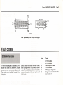
Fault codes
Obtaining fault codes. . . . . . . . . . . . . . . . . . . . . . . . . . . . . . . . . . . . . 32
Specifications
Vehicle
=
Year
Rover MEMS MPi
114 1.4 GTi 16V cat. . . . . . . . . . . . . . . . . . . . . . . . . . . . . . . . . . . . . . . .
214 1.4 OOHC 16V cat. . . . . . . . . . . . . . . . . . . . . . . . . . . . . . . . . . . . . .
220 2.0 OOHC 16V cat. . . . . . . . . . . . . . . . . . . . . . . . . . . . . . . . . . . . . .
220 2.0 OOHC 16V cat. . . . . . . . . . . . . . . . . . . . . . . . . . . . . . . . . . . . . .
220 2.0 OOHC 16V turbo cat. . . . . . . . . . . . . . . . . . . . . . . . . . . . . . . . .
414 1.4 OOHC 16V cat. . . . . . . . . . . . . . . . . . . . . . . . . . . . . . . . . . . . . .
414 1.4 OOHC 16V . . . . . . . . . . . . . . . . . . . . . . . . . . . . . . . . . . . . . . . . .
416 1.6 OOHC 16V . . . . . . . . . . . . . . . . . . . . . . . . . . . . . . . . . . . . . . . . .
420 2.0 OOHC 16V cat. . . . . . . . . . . . . . . . . . . . . . . . . . . . . . . . . . . . . .
420 2.0 OOHC 16V cat. . . . . . . . . . . . . . . . . . . . . . . . . . . . . . . . . . . . . .
420 2.0 OOHC 16V turbo cat. . . . . . . . . . . . . . . . . . . . . . . . . . . . . . . . .
620 2.0 OOHC 16V turbo. . . . . . . . . . . . . . . . . . . . . . . . . . . . . . . . . . . .
820i 2.0 OOHC 16V cat. . . . . . . . . . . . . . . . . . . . . . . . . . . . . . . . . . . . .
820 2.0 OOHC 16V turbo cat.
.
Metro 1.4 GTi OOHC 16V cat. .
MGF 1.8 OOHC 16V . . . . . . . . .
MGF 1.8 WC OOHC 16V . . . . .
.
.
.
.
.
.
.
.
.
.
.
.
.
.
.
.
.
.
.
.
.
.
.
.
.
.
.
.
.
.
.
.
.
.
.
.
.
.
.
.
.
.
.
.
.
.
.
.
.
.
.
.
.
.
.
.
.
.
.
.
.
.
.
.
.
.
.
.
.
.
.
.
.
.
.
.
.
.
.
.
Montego 2.0 EFi ...........................................
Montego 2.0 EFi AT ........................................
Rover MEMS SPi
Metro 1.4 16V . . . . . . . . . . . . . . . . . . . . . . . . . . . . . . . . . .
Metro 1.4 16V cat. . . . . . . . . . . . . . . . . . . . . . . . . . . . . . .
Metro 1.4 16V cat. . . . . . . . . . . . . . . . . . . . . . . . . . . . . . .
Mini Cooper 1.3i MT . . . . . . . . . . . . . . . . . . . . . . . . . . . . .
.
.
.
.
.
.
.
.
.
.
.
.
.
.
.
.
.
.
.
.
.
.
.
.
......
. . . . '. .
......
......
.
.
.
.
.
.
.
.
.
.
.
.
.
.
.
.
.
.
.
.
....
....
....
....
.
.
.
.
MiniCooper 1.3iAT ........................................
MiniCooper 1.3i Cabriolet ...................................
Mini1.3 ..................................................
111 .....................................................
114 .....................................................
:
--
.
114 1.4i
114 1.4i
214/414
214/414
214 1.4
414 1.4
414 1.4
& Cabrio
16V cat.
non cat.
cat. . . .
16V cat.
16V cat.
16V . . . .
cat.
..
..
...
...
...
...
.
.
.
.
.
.
..
.. .
...
...
...
...
...
.
.
.
.
.
.
.
.. ..
. ...
. ...
. ...
.. ..
. ...
. ...
.
.
.
.
.
.
.
.
.
.
.
.
.
.
.
.
.
.
.
.
.
...
...
...
...
...
...
...
.
.
.
.
.
.
.
..
..
..
..
..
..
..
.. .
...
...
...
...
...
...
.
.
.
.
.
.
.
.
.
.
.
.
.
.
...
...
...
...
...
...
. ..
.
.
.
.
.
.
.
..
..
..
..
..
. .
. .
...
...
...
...
...
. ..
...
.
.
.
.
.
.
.
.
.
.
.
.
.
.
....
... .
....
. ...
. ...
. ...
. ...
.
.
.
.
.
.
.
.
.
.
.
.
.
.
idle speed
CO%
1994
1996
1994
1996
1996
199p
1996
1996
1994
1996
1996
1996
1996
1996
1994
1996
1996
1992
1992
850 ::I:50
875 ::I:50
850 ::I:50
850 ::I:50
850 ::I:50
875 ::I:50
875 ::I:50
875 ::I:50
850 ::I:50
850 ::I:50
850 ::I:50
800 ::I:50
850 ::I:50
850 ::I:50
850 ::I:50
875 ::I:50
875::1:50
750 ::I:50
750 ::I:50
0.75 max
0.5 max
0.5 to 2.0
0.5 to 2.0
0.5 to 2.0
0.5 max
0.5 max
0.5 max
0.5 to 2.0
0.5 to 2.0
0.5 to 2.0
0.3 max
0.5 to 2.0
0.5 to 2.0
0.5 to 2.0
0.3 max
0.3 max
2.0 to 2.5
2.0 to 2.5
1990 to 1992
850 ::I:50
1990 to
1993 to
1991 to
1991 to
1993 to
1996 to
1995 to
1995 to
1991 to
1991 to
1989 to
1990 to
1992 to
1992 to
1995 to
850 ::I:50
850 ::I:50
850 ::I:50
0.5 to 2.0
0.5 to 2.0
0.5 to 2.0
0.5 to 2.0
0.5 to 2.0
0.5 to 2.0
0.4 max
0.4 max
0.4 max
0.75 max
0.75 max
0.5 to 2.0
0.5 to 2.0
0.5 to 2.0
0.5 to 2.0
0.5 to 2.0
1991
1992
1991
1992
1992
1992
1995
1995
1991
1992
1992
1994
1991
1992
1991
1995
1995
1989
1989
to
to
to
to
to
to
to
to
to
to
to
to
to
to
to
to
to
to
to
1992
1997
1992
1992
1997
1997
1997
1997
1994
1993
1992
1992
1996
1996
1996
850 ::I:50
850
850
850
875
875
875
850
850
850
::I:50
::I:50
::I:50
::I:50
::I:50
::I:50
::I:50
::I:50
::I:50
850 ::I:50
850 ::I:50
.I
14.2 Rover MEMS - MPi/SPi
- .:
,
Overview of system operation
~
-
--
1 Introduction
"-';:
~::e
, 11
ifl
11
I~I
.,u
1I
t!
I
i
!
I
II~
I~
Improvements
~
~I
I
~
!
i.
~_'C
.;-e
--=
.J"'
-
-
-e
-::e
--~
~
-
::..r;-
--
~a-
-
.-;;
--
"-
a) Version 1.2 (the first production version)
was designed for non-catalyst engines.
Although a catalyst could be fitted to the
exhaust system of vehicles with v1.2, the
catalyst would be of the non-regulated
type. Version 1.2 is identified by a single
36-pin multi-plug connector to the ECM.
b) Version 1.3 is a fully-regulated catalyst
version with ECM control of emission
controls. Version 1.3 is identified by two
multi-plug connectors (36-pin and 18-pin)
.
to the ECM.
reJ~as-en' 'llt'al' are-as-
in internal
--'...
---
-
-
- -~
:::.e
=e
.. .
......
;s
:-a
organisation
of Mt:MS, amr cnlbwan'1fie"
return of a single 36-pin multi-plug connector
to the ECM. However, turbocharged vehicles
retain the twin multi-plug connectors.
From mid-1994, MEMS version 1.8 has
been in production. Main changes are fitment
of a plastic inlet manifold and a new stepper
motor. The new stepper motor no longer acts
upon the linkage to the throttle plate, but uses
the motor to actuate a valve mounted within
the inlet manifold. Very late versions fitted to
KR6 and MGF vehicles utilise wasted spark
DIS and variable valve control NVc).
-
-
Please read this overview of Rover MEMS
operation in conjunction with Chapter 2,
which describes some of the functions in
more detail.
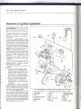
The Rover MEMS (Modular Engine
Management System) was developed jointly by
Rover and Motorola, and first appeared in 1989
on Montego 2.0 carburettor and then MPi
vehicles. MEMS is a fully-integrated system
that controls primary ignition, fuelling and idle
control from within the same ECM (see
illustration 14.1). When fitted to carburetted
engines, it is known as the ERICsystem.
MEMS was designed as a modular system
that was capable of controlling a wide range
of engines equipped with either MPi or SPi.
Additionally, the ECM is designed for a harsh
environment. It is robustly built, and
incorporates short-circuit
protection in
consideration of its location in the engine
compartment.
Prior to 19.94, there were three main
production versions of MEMS. These are
labelled versions 1.2, 1.3 and 1.6. From mid1994, version 1.8 was fitted.
The differences between the versions are
as follows:
Ba
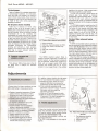
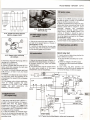
14.1 Rover MEMS(Rover214SPi).Multi-point systemsare very similar
1
2
3
4
5
6
7
8
Throttlepedal switch
Inertiaswitch
Fuelpump
TPS
Fuelpressure regulator
Fuelinjector
Stepper motor
ATS
9 Throttlebody heater (inlet
manifold)
10 CTS
11 Distributor
12 CAS
13 SO connector plug
14 ECM
15 Mainrelay
~-....
--
16 Fuelpump relay
17 Throttlebody heater
(inletmanifold)relay
18 Ignitioncoil
19 OS
20 OS relay
21 CFSV
22 Charcoalcanister
, -
~
:ec
...:=
....
Rover MEMS - MPi/SPi 14-3
2 Controlfunctions
.
!.:gnal
processing
The MEMS ECM is designed with three
main areas of control. These are the ignition,
fuel system and idle speed. The correct
ignition dwell and timing for all engine
operating conditions are calculated from data
provided by the CAS (crankshaft position and
speed), and the MAP sensor (engine load).
Basic ignition timing is stored in a threedimensional map, and the engine load and
speed signals determine the ignition timing.
The main engine load sensor is the MAP
sensor, and engine speed is determined from
the CAS signal.
Correction factors are then applied for
starting, idle, deceleration, and part- and fullload operation. The main correction factor is
engine temperature (CTS). Minor corrections
to timing and AFR are made with reference to
the air temperature sensor (ATS) and throttle
potentiometer sensor (TPS)signals.
The basic AFR is also stored in a threedimensional map, and the engine load and
speed signals determine the basic injection
pulse value. Using the speed/density method,
MEMS calculates the AFR from the pressure
in the inlet manifold (MAP) and the speed of
the engine (CAS).
This method relies on the theory that the
engine will draw in a fixed volume of air per
revolution. The AFR and the pulse duration
are then corrected on reference to ATS, CTS,
battery voltage and rate of throttle opening
(TPS). Other controlling
factors
are
determined by operating conditions such as
cold start and warm-up, idle condition,
acceleration
and deceleration.
During
acceleration, additional injection pulses are
provided at 80° crankshaft intervals.
MEMS accesses a different map for idle
running conditions,
and this map is
implemented whenever the idle switch is
closed and the engine speed is at idle. Idle
speed during all warm-up and normal hot
running conditions is maintained by the idle
speed stepper motor. However, MEMS makes
small adjustments to the idle speed by
advancing or retarding the timing, and this
results in an ignition timing that is forever
changing during engine idle.
Basic ECM operation
Once the ignition is switched on, a voltage
supply to ECM pin 11 is made from the
ignition switch. This causes the ECM to
connect pin 4 to earth, so actuating the main
fuel injection relay. A relay switched voltage
supply is thus made to ECM pin 28, from
terminal 87 of the main fuel injection relay.
Depending on model, the coil is supplied with
voltage from either the main relay or from the
ignition switch direct.
The majority of sensors (other than those
that generate a voltage such the CAS, KS and
CID sensor), are now provided with a 5.0-volt
reference supply from a relevant pin on the
ECM. When the engine is cranked or run, a
speed signal from the CAS causes the ECM to
earth pin 20 so that the fuel pump will run.
Ignition and injection functions are also
activated. All actuators (Injectors, ISCV, FTVV
etc) , are supplied with nbv from the main
relay, and the ECM completes the circuit by
pulsing the relevant actuator wire to earth.
Self-diagnostic function
MEMS provides a serial port for diagnostic
and system tuning purposes. The port allows
two-way communication, so that certain
parameters can be changed (ie CO value) and
actuation of various output components.
In addition, a self-test capability regularly
examines signals from the engine sensors, and
internally logs a code in the event of a fault
being present. This code can be extracted
from the MEMS serial port by a suitable FCR. If
the fault clears, the code will remain logged
until the FCR is used to erase it from memory.
LOS (limp-home mode)
MEMS has a limited operating strategy
(LOS)or limp-home facility, and in the event of
a serious fault in one or more of the sensors,
the EMS will substitute a fixed default value in
place of the defective sensor.
For example, in limp-home mode the
coolant temperature sensor (CTS)value is set
to 60°C, the ATS is set to 35°C, and engine
load is based on rpm. The engine may
actually run quite well with failure of one or
more minor sensors. However, since the
substituted values are those of a hot engine,
cold starting and running during the warm-up
period are likely to be less than satisfactory.
Also, failure of a major sensor, ie the MAP
sensor, will lead to a considerable reduction in
performance.
Adaptive and
non-volatile memory
Over a period of time, the ECM will learn the
best idle position for a particular engine irrespective of age, engine condition and load,
so that the correct idle speed is always
maintained. The adaptive idle settings are
stored in non-volatile memory. Consequently,
a replacement ECM will need some time to relearn the system parameters before proper
idle control is restored. A tune-up with a
suitable FCR is recommended whenever a
new ECM is fitted.
Faults identified by the self-diagnostic
function will also be stored in non-volatile
memory, and will remain there until erased by a
suitable FCR. This allows the self-diagnostic
function to retain data of an intermittent nature.
Adaptive idle measurements and fault
codes retained in non-volatile memory cannot
be lost
even if the vehicle battery is
removed. If the ECM from one vehicle is
-
transferred to another vehicle, the contents of
non-volatile memory will also be transferred,
unless a FCR is used to erase the codes and
tune the engine to the new set-up.
Reference voltage
Voltagesupply from
the ECM to the engine
sensors is made at a 5.0-volt
reference level.
This ensures
a stable
working
voltage,
unaffected by variations in system voltage.
The earth return connection for most engine
sensors is made through ECM pin number 30,
and this pin is not directly connected to earth.
The ECM internally connects pin number 30 to
earth via the ECM earth pin that is directly
connected to earth.
Signal shielding
To reduce interference (RFI), a number of
sensors (eg the crank angle sensor, knock
sensor and oxygen sensor) use a shielded
cable. The shielded cable is connected to the
main ECM earth wire at terminal 29 to reduce
interference to a minimum.
3 Primary trigger
Crank angle sensor (CAS)
The primary signal to initiate both ignition
and fuelling emanates from a CAS mounted
next to the flywheel. The CAS consists of an
inductive magnet that radiates a magnetic field.
The flywheel incorporates a reluctor disk
containing 34 steel pins set at 10° intervals. As
the flywheel spins, and the pins are rotated in
the magnetic field, an AC voltage signal is
generated to indicate speed of rotation. The
two missing pins (set at 180° intervals) are a
reference to TDC, and indicate crankshaft
position by varying the signal as the flywheel
spins. One missing pin indicates TDC for
cylinders 1 and 4, and the other missing pin
indicates TDC for cylinders 2 and 3.
The peak-to-peak voltage of the speed signal
can vary from 5 volts at idle to over 100 volts at
6000 rpm. The ECM microprocessor contains
an analogue-to-digital converter to transform
the AC pulse into a digital signal.
:I
,
I
I
14
4 Ignition
Data on engine load (MAP) and engine
speed (CAS)are collected by the ECM, which
then refers to a three-dimensional digital
ignition map stored within its microprocessor.
This map contains an advance angle for basic
load and speed operating conditions. The
advance angle is corrected after reference to
engine temperature (CTS), so that the best
ignition advance angle for a particular
operating condition can be determined.
loo
14-4 Rover MEMS - MPi/SPi
Amplifier
The MEMS amplifier contains the circuitry
for switching the coil negative terminal at the
correct moment to instigate ignition. The
signal received by the amplifier from the CAS
trigger is of an insufficient level to complete
the necessary coil switching. The signal is
thus amplified to a level capable of switching
the coil negative terminal.
The amplifier circuitry is contained within
the ECM itself, and the microprocessor
controls the ignition dwell period for each
condition of engine speed and battery
voltage.
Dwell operation in MEMS is based upon the
principle of the 'constant-energy currentlimiting' system. This means that the dwell
period remains constant at about 3.0 to
3.5 ms, at virtually all engine running speeds.
However, the dwell duty cycle, when
measured in percent or degrees, will vary as
the engine speed varies.
Ignition coil
The ignition coil utilises low primary
resistance in order to increase primary current
and primary energy. The amplifier limits the
primary current to around 8 amps, and this
permits a reserve of energy to maintain the
required spark burn time (duration). In DIS
systems, the coils are double-ended, and fire
two spark plugs together. The KR6 utilises
three DIS coils, and the MGF two DIS coils.
cylinder or cylinders that are knocking. The
knock sensor is mounted on the engine block,
and consists of a piezo-ceramic measuring
element that responds to engine noise
oscillations. This signal is converted to a
voltage signal that is proportional to the level
of knock, and returned to the ECM for
evaluation and action.
The ECM will analyse the noise from each
individual cylinder, and uses a sophisticated
technique to recognise knock as distinct to
general engine noise.
Initially, timing will occur at its optimal
ignition point. Once knock is identified, the
microprocessor retards the ignition timing for
that cylinder in steps of 0.625° until either
knock ceases or a maximum retard of 10° is
reached. The timing is then advanced in
0.65° increments until the reference timing
value is achieved or knock occurs again,
when the processor will retard the timing once
more. This procedure continually occurs so
that all cylinders will consistently run at their
optimum timing.
If a fault exists in the KCP, knock control
sensor or wiring, an appropriate code will be
logged in the self-diagnostic unit, and the
ignition timing retarded by 10.5° by the LOS
program.
5 Fuel injection
Distributor
In the MEMS system, the distributor only
serves to distribute the HT current from the
coil secondary terminal to each spark plug in
firing order. The distributor is located on the
inlet camshaft at the cylinder No 4 end. The
distributor contains a rotor arm, and also has
a deflector plate and oil drain to prevent oil
seal leakage from contaminating
the
distributor cap and rotor arm.
Distributorless
ignitionsystem (DIS)
Vehicles with the KR6 V6 engine, and those
with the four-cylinder MGF WC engine utilise
wasted spark DIS ignition. The MGF without
WC is equipped with a distributor. Refer to
Chapter 2 for a detailed description of wasted
spark and DIS.
Knock sensor
(some MPi vehicles)
The optimal ignition timing (at engine
speeds greater than idle) for a given highcompression engine is quite close to the point
of onset of knock. However, running so close
to the point of knock occurrence means that
knock will certainly occur on one or more
cylinders at certain times during the engine
operating cycle.
Since knock may occur at a different
moment in each individual cylinder, MEMS
employs a knock control processor (KCP)
built into the ECM to pinpoint the actual
Rover has adopted three distinct methods
for providing fuel to the engines equipped
with MEMS. The methods are simultaneous
multi-point injection (MPi), sequential multipoint injection (MPi) and single-point injection
(SPi).
Because of the modularity of MEMS, very
little difference exists between the implementation of each system on the various engines.
First, a description of common features and a
description of each type follows.
The injector(s) are switched using two
circuits. Operation depends on the principle
that more current is required to open an
injector than to keep it open. This kind of
system is often termed 'current-controlled'.
Once the injector is open, a second circuit
rapidly pulses the injector to earth. The
switching is so rapid that the injector is
effectively held open, and less current is
required during the operation. Advantages of
this arrangement include a reduction in
injector
operating
temperature,
and
immediate injector closure once the holding
circuit is switched off.
The MEMS ECM contains a fuel map with
an injector opening time for basic conditions
of speed and load. Information is then
gathered from engine sensors such as the
MAP sensor, CAS, CTS, ATS and TPS. As a
result of this information, the ECM will look up
the correct injector pulse duration right across
the engine rpm, load and temperature range.
The fuel injector is a magnetically-operated
solenoid valve that is actuated by the ECM.
Voltage to the injectors is applied from the
fuel pump relay, and the earth path is
completed by the ECM for a period of time
(called pulse duration) of between 1.5 and
10 milliseconds. The pulse duration is very
much dependent upon engine temperature,
load, speed and operating conditions. When
the magnetic solenoid closes, a back-EMF
voltage of up to 60 volts is initiated.
The amount of fuel delivered by the
injector(s) is determined by the fuel pressure
and the injector opening time - otherwise
known as the pulse duration. The ECM
controls the period of time that the injector is
held open, and this is determined by the
signals from the various sensor inputs. During
engine start-up from cold, the pulse duration
and number of pulses (frequency) are
increased to provide a richer air/fuel mixture.
Over-speed fuel cut-off
(rev limiter)
. To prevent over-high engine speeds, which
might otherwise lead to engine damage,
above 6250 rpm (MPi) and 6860 rpm (SPi),
MEMS inhibits the injector earth path. As the
engine speed drops below 6150 rpm and
6820 rpm respectively, fuel injection is
reinstated.
Deceleration fuel cut-off
A deceleration fuel cut-off is implemented
during engine over-run conditions, to improve
economy
and
reduce
emissions.
The
conditions
for over-run to be implemented
are:
a) Throttle closed (throttle pedal contacts
closed).
b) Engine speed above 2600 rpm (MPij or
1500 rpm (SPij.
c) Coolant temperature above BO°C.
d) Once the engine speed drops below
2600 rpm or 1500 rpm respectively, fuel
injection is reinstated.
Multi-point
injection
simultaneous)
(MPi
-
The MPi system consists of one injector for
each cylinder, mounted in the inlet port, so
that a finely-atomised fuel spray is directed
onto the back of each valve. The injectors are
all pulsed simultaneously, twice per engine
cycle. Half of the required fuel per engine
cycle is injected at each engine revolution.
Fuel will briefly rest upon the back of a
valve before being drawn into a cylinder.
Unlike other simultaneous systems, the
injectors are all connected to the ECM via
separate wires to separate ECM driver pins.
Multi-point injection
(MPi sequential)
-
The sequential system functions in a similar
manner to the simultaneous system.
However, with reference to the signal from the
cylinder identification (CID) sensor (only
e
E
t
t
c
e
r
r
11
s
s
n
v
d
P
c
P
A
c,
tt
rE
a
'e
IT
tt
fl
C
nl
Rover MEMS - MPi/SPi 14-5
present in sequential systems), each injector
is actuated as its inlet valve opens, in firing
order.
s
Single-point fuel injection (SPi)
The SPi system consists of a single injector
mounted in the throttle body. The amount of
fuel delivered by the injector is determined by
the fuel pressure and the injector opening
time - otherwise known as the pulse duration.
In SPi engines, fuel is injected into the inlet
manifold, where it mixes with air. The
depression produced by a descending piston
causes the resulting air/fuel mixture to be
drawn into each cylinder. Otherwise, operation
Ott{1einjector is very similar to operation of the
inje~d
to the MPi systems.
r
rE
~
Ir
,s
rE
~
~
ar:
e
Cylinder identification sensor
(sequential injection only)
. In simultaneous MPi systems, the ECM
does not have to recognise No 1 cylinder, or
ind~ed even the firing order. When the
crankshaft or distributor provides a timing
signal, the correct cylinder is identified by the
mechanical position of the crankshaft,
camshaft, valves and ignition rotor.
On models fitted with sequential injection,
the ECM must determine which cylinder is on
its firing stroke, and the CID sensor provides
the appropriate signal. The CID sensor
operates on the inductive principle, and is a
permanent magnet device mounted adjacent
to the camshaft. A reluctor is attached to the
camshaft, divided into four equal quadrants.
Each quadrant contains a unique number of
teeth, numbering from one to four. Because
the AC-generated signal from each quadrant
is unique, the ECM is able to determine the
camshaft position and cylinder sequence.
The reluctor should be handled with
extreme care, due to the fragile sintered
material used in its construction. Any impact
may cause cracking or a stress fracture.
1-:::'g-e
p
s
I:ec
'Cc
~E
MAP sensor
)r fa"'
tsc
Clad
s are
IQ ne
tg~e
Of a
rde'
tr-e
~ .a
inS.
The main engine load sensor is the MAP
sensor. A vacuum hose connects the MAP
sensor (located within the ECM) and the inlet
manifold (see illustration 14.2). Manifold
vacuum acts upon the MAP sensor
diaphragm, and the ECM converts the
pressure into an electrical signal. MAP is
calculated from the formula: Atmospheric
Pressure less Manifold Pressure = Manifold
Absolute Pressure.
Using the speed/density method, MEMS
calculates the AFR from the MAP signal and
the speed of the engine (CAS). This method
relies on the theory that the engine will draw in
a fixed volume of air per revolution.
The.inlet manifold on the MPi models is a
'dry' manifold. Since fuel does not enter the
manifold
i~"a:
ster""
r" tt"e
0'"
I
- due
to injection
being made onto
the back of the inlet valve, there is no risk of
fuel being drawn into the MAP sensor to
contaminate the diaphragm, and a fuel trap is
not used. However, on Rover 820 models
14.2 SPi: The MAP sensor vacuum hose
connections to the fuel trap at the air filter.
The hoses are colour coded to ensure
correct refitting
under certain operating conditions, fumes are
drawn from the rocker box into the MAP
sensor vacuum hose and then to the ECM,
where contamination can occur. This can be
prevented by fitting the fuel trap used on SPi
models.
The inlet manifold on the SPi models is a
'wet' manifold. Fuel is injected into the inlet
manifold, and there is a risk of fuel being
drawn into the MAP sensor to contaminate
the diaphragm. This is prevented by running
the vacuum hose upward to the air filter,
through a fuel trap and then to the ECM
(which contains the MAP sensor).
Air temperature sensor (A TS)
The ATS is mounted in the air inlet casing
(MPi) or air filter casing (SPi), and measures
the air temperature before it enters the inlet
manifold. Because the density of air varies in
inverse proportion to the temperature, the
ATS signal allows more accurate assessment
of the volume of air entering the engine.
The open-circuit supply to the sensor is at a
S.O-volt reference level, and the earth path is
through the sensor return. The ATS operates
on the NTC principle. A variable voltage signal
is returned to the ECM based upon the air
temperature. This signal is approximately
2.0 to 3.0 volts at an ambient temperature of
20°C, and reduces to about 1.S volt as the
temperature rises to around 40°C.
Although the air filter casing used on SPi
models contains a thermal valve system, the
thermal valve has no bearing on the AFR, and
the air temperature is calculated solely by
reference to the ATS.
CO
engine is cold, the resistance is quite high.
Once the engine is started and begins to
warm-up, the coolant becomes hotter, and
this causes a change in the CTS resistance.
As the CTS becomes hotter, the resistance of
the CTS reduces (NTC principle), and this
returns a variable voltage signal to the ECM
based upon the coolant temperature.
The open-circuit supply to the sensor is at a
S.O-volt reference level, and this voltage
reduces to a value that depends upon the
CTS resistance. Normal operating temperature is usually from 80° to 100° C. The
ECM uses the CTS signal as a main correction
factor when calculating ignition timing and
injection duration.
Throttle potentiometer sensor
(TPS)
A TPS is provided to inform the ECM of rate
of acceleration. The TPS is a potentiometer
with three wires. A S.O-volt reference voltage
is supplied to a resistance track, with the
other end connected to earth. The third wire is
connected to an arm which wipes along the
resistance track, and so varies the resistance
and voltage of the signal returned to the ECM.
From the voltage returned, the ECM is able
to calculate just how quickly the throttle is
opened. From model year 1993 onwards, the
TPS also informs the ECM of idle position with
a voltage of approximately 0.6 volts.
Throttle pedal switch
Until the 1993 model year, the throttle pedal
switch indicated a closed throttle to the ECM.
The ECM was then able to recognise the idle
speed condition and also deceleration. From
1993 models year, MEMS recognised the
closed throttle condition with reference to the
TPS signal.
Stepper motor
The stepper motor is an actuator that the
ECM uses to automatically control idle speed
during normal idle and during engine warm-up
(see illustration 14.3). When electrical loads,
such as headlights or heater fan etc are
switched on, the idle speed would tend to
drop. In this event, the ECM advances the
ignition timing to make a small speed change,
and indexes the stepper motor for a greater
change in idle speed. During periods of cold
adjustment
The CO value at idle speeds can only be
adjusted through the medium of a FCR
attached to the serial port. It is not possible to
make this adjustment by any other means. On
catalyst-equipped models, the CO is nonadjustable.
Coolant
(CTS)
temperature sensor
The CTS is incorporated in the cooling
system, and contains a variable resistance
that operates on the NTC principle. When the
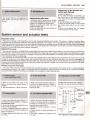
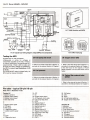
14.3 Rover 820 stepper motor
1 Stepper motor
2 Ignition coil
3 ECM
14-6 Rover MEMS - MPi/SPi
running, the stepper motor will open the
throttle so that the engine rpm willbe set to a
suitable fast idle speed. Also, on sensing low
battery voltage, the ECMwillincrease the idle
speed to allowgreater alternator output.
The stepper motor is a DC motor, provided
with a voltage supply from the system relay.
The motor windings are earthed through four
earth wires. By earthing various combinations
of the four wires, the ECMis able to indexthe
motor to its correct position. The ECM
controls idle speed by using the stepper
motor in one of two diverse ways.
Throttle plate actuator
The stepper motor controls a cam and
push rod through a reduction gear. The
push rod contacts the throttle lever, which
actuates the throttle plate and so maintains
the correct idle speed. Maximum movement
of the stepper motor is 3.75 revolutions, and
this is accomplished by 180 steps of 7.5°. The
reduction gear reduces the actual cam
movement to 150°.
Inlet manifold air valve
"
.'It
I
I,
I.'
The air valve stepper motor is an actuator
that the ECM uses to automatically control
idle speed during normal idle and during
engine warm-up. When the throttle is closed,
the throttle valve is locked in a position where
very little air passes by. The throttle position
then, willhave no effect upon the idle speed.
A by-pass port to the throttle plate is
located in the inlet manifold. A valve is
positioned inthe port. As the valve moves, the
volume of air passing through the port will
vary, and this directly affects the idle speed.
The idle speed then, depends upon the
position of the stepper air valve in the by-pass
port. This method of idle control is fitted to
some models (principally those with the
plastic inlet manifold)fromthe middle of 1994.
I:
I,
JI
I:
U
...!....
14.4 Rover 820 MEMS multi-function
(MFU)
MFU multi-plug disconnected
unit
approximately 75° C is reached, the ECM tums
off the relay. If the ignition is switched to the
'on' position and the engine is not cranked, the
ECM will turn off the manifold heater after a few
seconds. The manifold heater will also be
turned off to prevent battery overload
engine cranking.
during
MEMS relays and MFU
The MEMS electrical system is controlled by
a number of relays. The relays utilised in some
vehicles are conventional in construction and
operation. However, some models are
equipped with an MFU (multi-function unit).
Main and fuel pump relays
(Rover 214, 414, 220 and 420 models)
A permanent voltage supply is made to
main relay terminals 30 and 86, and fuel pump
relay terminal 30, from the battery positive
terminal. When the ignition is switched on, the
ECM earths terminal 85 through ECM terminal
number 4, which energises the relay winding.
This causes the main relay contacts to close,
and terminal 30 is connected to the output
circuit at terminal 87. A voltage supply is thus
Adaptive idle control
output at terminal 87. Terminal 87 supplies
Since the idle control is adaptive, over a voltage to the injector(s), ECM terminal 28, the
period of time, the ECM will learn the best
ignition coil terminal 15 (some models) and
position for a particular engine irrespective the stepper motor. In addition, voltage is
of age, engine condition and load, so that the supplied to the manifold heater relay terminal
correct idle speed is always maintained. 86 on SPi vehicles.
Consequently, a replacement ECM willneed
When the ignition is switched on, a voltage
sometimeto re-learnthe systemparameters supply is made to fuel pump relay terminal 86,
beforeproper idle control is restored.
and the ECM briefly earths relay contact 85 at
Adaptive idle measurements are retained in ECM terminal 20, which energises the fuel
non-volatile memory and cannot be lost - pump relay winding. This causes the fuel
even if the vehicle battery is removed. On pump relay contacts to close, and connects
models prior to 1993, idle position was voltage from terminal 30 to terminal 87.
determinedby an idle switch located on the Voltage is thereby output to the fuel pump
acceleratorpedal.From1993, this switch has circuit. After approximately one second, the
been discontinued, and the idle positien is ECM opens the circuit and the pump stops.
now determined by the TPS.
This brief running of the fuel pump allows
pressure .to build within the fuel pressure
Manifold
heater
(SPi)
lines, and provides for an easier start.
The ECM controls the manifold heater
The fuel pump circuit will then remain open
through a relay. This heater works on the PTC until the engine is cranked or run. Once the
principle, and allows a greater current to
ECM receives a speed signal from the CAS,
quickly heatthe inlet manifold during the warm- the fuel pump winding will again be energised
up period. This allows better driveability during by the ECM, and the fuel pump will run until
engine warm-up. Once a preset temperature of the engine is stopped.
-
11
.,
Multi-function unit (MFU)main and
fuel pump relays (all Rover models
other than 214, 414, 220, and 420)
The MFU is a sealed box that contains four
sets of relay contacts. The two relays always
used are a main and fuel pump relay, and the
other two will be chosen from the starter, OS or
manifold heater relays (see illustration 14.4).
If anyone of the relays fails, the whole MFU
must be replaced. However, the relay
contacts are heavy-duty, and failure is a fairly
rare occurrence.
Two multi-plugs of 8-pin and 6-pin
configuration connect the MFU with MEMS
wiring. The multi-plug terminal designations
are identified by the prefix 8 or 6 for the multiplug, and the suffix 1 to 8 or 1 to 6 for the
actual terminal. So 8/1 would identify the
terminal as number one terminal in the eight
8-pin multi-plug. There follows a typical
description, but be warned that wiring of
some MFU's may differ.
A permanent voltage supply is made to the
MFU main relay terminals 8/6 and 8/7 from the
battery positive terminal. When the ignition is
switched on, the ECM earths terminal 6/3
through ECM terminal number 4, which
energises the relay winding. This causes the
main relay contacts to close, and output
voltage is available at MFU terminal 8/1, 8/3
and 8/8. These output terminals supply voltage
to the injector(s),ECM terminal 28, the ignition
coil terminal 15 models) and the stepper motor.
Connections to individual components vary
according to vehicle. In addition, voltage is
intemally supplied to the manifold heater relay
inside the MFU on SPi vehicles.
When the ignition is switched on, a voltage
supply is made to MFU terminal 6/2, and the
ECM briefly earths MFU contact 6/1 at ECM
terminal 20. This energises the fuel pump
relay, and causes the fuel pump relay
contacts to close. Terminal 8/6 is thus
connected to terminal 8/4, and voltage is
thereby output to the fuel pump circuit. After
approximately one second, the ECM opens
the circuit, and the pump stops. This brief
running of the fuel pump allows pressure to
build within the fuel pressure lines, and
provides for an easier start.
The fuel pump circuit will then remain open
until the engine is cranked or run. Once the
ECM receives a speed signal from the CAS,
the fuel pump winding will again be energised
by the ECM, and the fuel pump will run until
the engine is stopped.
Engine shut down
On switching off the engine, the ECM keeps
the relay (or MFU) earth energised for up to 30
seconds. This holds the voltage supply to the
ECM, which-thef-l actuates the stepper motor
to its fully closed'
osition (thus preventing
engine run-on). After a
seconds more, the
ECM actuates the stepper motor to a position
where it slightly opens the throttle plate, ready
for the next engine start.
Rover MEMS - MPi/SPi 14-7
Fuel rail temperature sensor
(FRTS) some MPi models with
-
14.5 Fuel delivery circuit
for SPi engines
1 Fuel tank
2 Fuelpump
3 Swirlpot
4 Non-returnvalve
5 Fuel filter
6 Fuelinjector
7 Fuelpressure
regulator
8 Fuelreturnline
9 Venturi
manual transmission
The FRTS senses the temperature of the
fuel in the fuel rail, and the value is logged by
the ECM at the time that the engine is shut
down. When the engine is restarted, the ECM
compares the start-time temperature with the
temperature recorded at shut-down. If the
new temperature is higher, the injection pulse
is lengthened during the cranking operation to
provide hot start enrichment. This enrichment
decays at a fixed rate.
Fuel pressure system
Note: Uniquely, the Montego utilises a rollermounted outside the fuel tank.
Voltageto the fuel pump is applied through a
1.0 ohm ballast resistor. This reduces the
voltage and current applied to the fuel pump,
and ensures cooler running. Duringcranking,
when a higher voltage level is required, voltage
is applied directly to the pump from the starter
solenoid and the resistor is by-passed. Full nbv
is thus applied to the fuel pump.
The fuel system includes a fuel tank, with
swirl pot and a submerged fuel pump. The
fuel pump draws fuel from the tank and
pumps it to the fuel rail via a fuel filter (see
illustration 14.5).
Switching the ignition key on causes the
ECM to energise the fuel pump relay for
approximately one second so that the fuel
system is pressurised. The fuel pump relay is
then switched off, to await a cranking or
running signal. The swirl pot prevents air from
entering the fuel supply line, by ensuring that
the pick-up strainer is always immersed in fuel
type fuel pump
when the fuel level is low
- even
during fuel
movement due to centrifugal forces acting
upon the vehicle.
The pump is of the 'wet' variety, in that fuel
actually flows through the pump and the
electric motor. There is no actual fire risk,
because the fuel drawn through the pump is
not in a combustible condition. The fuel pump
assembly comprises an outer and inner gear
assembly, termed a 'gerotor'. Once the pump
motor becomes energised, the gerotor
rotates, and as the fuel passes through the
individual teeth of the gerotor, a pressure
differential is created. Fuel is drawn through
the pump inlet, to be pressurised between the
rotating gerotor teeth, and discharged from
the pump outlet into the fuel supply line.
To reduce the effect of fluctuations in fuel
pressure, a pulsation damper is provided in
the pump outlet, thereby preventing hydraulic
knock. The pump is protected from overpressurising by a' relief valve mounted in the
inlet side of the pump. Once the engine is
running, fuel is fed through a non-return valve
and fuel filter to the multi-point injector rail or
the single throttle body injector.
To prevent pressure loss in the supply
system, a non-return valve is provided in the
fuel pump outlet. When the ignition is
switched off, and the fuel pump ceases
operation, pressure is thus maintained for
some time. Temperature in the fuel rail is
monitored by a fuel rail temperature sensor
(FRTS)in manual transmission models; a fuel
restrictor and fuel temperature sensor (FTS)is
used in automatic transmission models.
Fuel pressure regulator (MPi)
Fuel pressure in the fuel rail is maintained at
a constant 2.5 bar by a fuel pressure regulator
fitted on the outlet side of the fuel rail. The fuel
pump normally provides much more fuel than
is required, and surplus fuel is thus returned
to the fuel tank via a return pipe. In fact, a
maximum fuel pressure in excess of 5 bar is
possible in this system.
The pressure regulator consists of two
chambers, separated by a diaphragm. The
upper chamber contains a spring, which
exerts pressure upon the lower chamber and
closes off the outlet diaphragm. Pressurised
fuel flows into the lower chamber, and this
exerts pressure upon the diaphragm. Once
the pressure exceeds 2.5 bar, the outlet
diaphragm is opened, and excess fuel flows
back to the fuel tank via a return line.
A vacuum hose connects the upper
chamber to the inlet manifold, so that
variations in inlet manifold pressure will not
affect the amount of fuel injected. This means
that the pressure in the rail is always at a
constant pressure above the pressure in the
inlet manifold. The quantity of injected fuel
thus depends solely on injector opening time,
as determined by the ECM, and not on a
variable fuel pressure.
At idle speed with the vacuum pipe
disconnected, or with the engine stopped and
the pump running, or at full-throttle, the
system fuel pressure will be around 2.5 bar. At
idle speed (vacuum pipe connected), the fuel
pressure will be approximately 0.5 bar under
the system pressure.
Fuel temperature sensor (FTS)
and fuel restrictor solenoid
-
(FRS) MPi models with
automatic transmission)
In vehicles with automatic transmission, the
FRTS is replaced with a fixed resistance so
that after-start enrichment will never be
implemented. When the fuel rail temperature
exceeds 90°C, the FTS closes to complete
the earth circuit to the FRS. The FRS is
energised to cause a restriction in the fuel
return line. The increased fuel pressure
thereby improves starting.
Inertia switch
The inertia switch is a safety cut-out switch,
used to isolate the fuel pump in the event of a
very sharp deceleration - eg a collision.Once
the switch has been activated, the electrical
supply to the fuel pump remains open-circuit
until the inertia switch has been reset by
raising the button (see illustration 14.6).
Temperature gauge
(Montego only)
The engine coolant temperature gauge on
the instrument panel is connected to earth
through the ECM. MEMS actuates the gauge
and warning lamp by rapidly pulsing the ECM
connection to earth. This produces a square
waveform of variable frequency and duty
cycle. The frequency increases as the engine
temperature increases, and the hotter the
engine, the lower will the average voltage
become. In addition, the duty cycle will also
change.
Fuel pressure regulator (SPi)
Fuel pressure of approximately one bar is
controlled by the pressure regulator, which is
located within the throttle body next to the injector. As the pressure rises over the predetermined level, excess fuel is returned to
the fuel tank via a return pipe.
14.6 Reset inertia switch
by depressing plunger
14.8 Rover MEMS - MPi/SPi
Turbocharger
Referto Chapter 2 for a detailed description
of turbocharger operation. An intercooler,
which is a kind of air radiator, for cooling is
used in Rover turbo models. Boost control is
controlled by the ECM so that maximum use
is made of the turbo during appropriate
operating conditions.
Air by-pass (turbo models)
Turbo lag is reduced on Rover turbo
models by use of an air by-pass valve. A
sensing pipe connects the by-pass valve with
the inlet manifold. When the turbine supplies
compressed air to the manifold, the
compressed air pushes upon the air by-pass
valve, and it remains shut. Duringdeceleration
or light load when the turbo is inactive, the
manifold contains depressed air (a vacuum)
and the depression willopen the air by-pass
valve. Air pressure from the impellerwheel is
circulated throughout the turbocharger
housing, and prevents a back pressure
forming. The turbine slows very little, and
turbo lag is much reduced when the
accelerator is re-applied.
6 Catalyticconverter and
emission control
'
1
I.I
1
From January 1993, all new cars in the UK
are fitted with a catalyst as standard
equipment.
~
14.7 Carbon filter solenoid valve (CFSV)
1 Wiringconnector
2 Inlethose, charcoalcanister to GFSV
3 Outlet hose, GFSV to throttlebody
4 G-cIip
5 Inlethose, connector
6 0 ring
7 GFSV
The MEMS injection system fitted to
catalyst vehicles implements a closed-loop
control system, so that exhaust emissions
may be reduced. Closed-loop systems are
fitted with an oxygen sensor (OS) which
monitors the exhaust gas for its oxygen
content. A low oxygen level in the exhaust
signifiesa rich mixture.A high oxygen level in
the exhaust signifiesa weak mixture.
The OS only produces a signal when the
exhaust gas, has reached a minimum
temperature of approximately300°C. In order
that the OS will reach optimum operating
temperature as quickly as possible after the
engine has started, the OS contains a heating
element.
The OS heater supply is made from the OS
relay terminal number 87. This ensures that
the heater willonly operate whilst the engine
is running. Under full-load conditions, the
heater supply is cut-off by the ECM by
inhibitingthe earth path of the OS relay. The
KR6engine utilises twin oxygen sensors, one
for each bank.
Carbon filter solenoid valve
(CFSV)
A CFSV and activated carbon canister will
also be employed to aid evaporative emission
control (see illustration 14.7). The carbon
canister stores fuel vapours until the CFSVis
actuated by MEMS.CFSV actuation occurs
when the engine temperature is above 70°C,
the engine speed above 1500 rpm and the
MAPsensor returns less than 30 kPa.
When the CFSV is actuated by MEMS,the
valveis modulated on and off,and fuelvapours
are drawn into the inletmanifoldto be bumt by
the engine during normal combustion. So that
engine performance will not be affected, the
CFSV remains closed during cold engine
operation and also during engine idle.
Adjustments
7 Adjustmentpre-conditions
~
'I
I
1 Ensure that all of these conditions are met
before attempting to make adjustments:
a) Engine at operating temperature. Engine
oilat a minimumtemperatureof aOOG.
~
b)
I
c)
d)
e)
f)
g)
h)
ij
j)
k)
I)
.1
I
l
A journey of at least 4 miles is advised
(particularly so if equipped with A1).
Ancillary equipment (allengine loads and
accessories) switched off.
AT engines: Transmission in N or P.
Engine mechanically sound.
Engine breather hoses and breather
system in satisfactory condition.
Induction system free from vacuum leaks.
Ignition system in satisfactory condition.
Air filter in satisfactory condition.
Exhaust system free from leaks.
Throttle cable correctly adjusted.
No fault codes logged by the EGM.
OS operating satisfactorily (catalyst
vehicles with closed-loop control).
2 In addition, before checking the idle speed
and CO value stabilise the engine as follows.
a) Stabilise the engine. Raise the engine
speed to 3000 rpm for a minimum of
30 seconds, and then let the engine idle.
b) If the cooling fan operates during
adjustment, wait untilit stops, re-stabilise
the engine, and then restart the
adjustment procedure.
c) Allow the GOand idlespeed to settle.
d) Make allchecks and adjustments within
30 seconds. If this time is exceeded, restabilise the engine and recheck.
JSC~-'I
8 Throttleadjustments
1 Clean the throttle valve and surrounding
areas with carburettor cleaner. Blow-by from
the breather system often causes sticking
problems here (see illustration 14.8).
2 The throttle valve position is critical, and
must not be disturbed.
3 The TPS in not adjustable for this range of
engines.
14.8 Adjust the throttle lost motion gap
see text
1 The clearance should be
equal on both sides
2 Adjustment nut
3 Locknut
-
Rover MEMS - MPi/SPi 14.9
--- t-- - -
- -----
, - -- -I
9 700
.p...
Adjustment of the throttle lost
motion gap (typical)
10 Idle adjustments
timingchecks
----
1 The ignition timing is not adjustable on
these models, and timing marks are not
provided.
Adjustments
(idle tune)
1 Idle speed and CO level (non-cat models
only) are only adjustable through the use of a
suitable FCR connected to the serial port.
2 Before connecting the FCR, check the
throttle lost motion gap.
3 After completing the idle tune, recheck the
throttle lost motion gap.
4 Switch the ignition on.
5 From within the engine compartment, use
the throttle lever to fully open the throttle
valve. The ECM will index the stepper motor
to 25 steps.
6 Allow the throttle valve to fully close.
7 Adjust the throttle cable so that an equal
gap exists either side of the lost motion
lever.
8 Switch off the ignition key. The stepper
motor will revert to normal control.
System sensor and actuator tests
Important notes
Please refer to Chapter 4, which describes common test procedures applicable to this system. The routines in Chapter 4 should be read in
conjunction with the component notes and wiring diagrams presented in this Chapter. The wiring diagrams and other data presented in this
Chapter are necessarily representative of the system depicted. Because of the variations in wiring and other data that often occurs, even between
similar vehicles in any particular VM's range, the reader should take great care in identification of ECM pins, and satisfy himself that he has
gathered the correct data before failing a particular component.
MEMSECMterminals
The multi-plug terminals at the MEMS ECM are gold-plated, and care must be taken that the plating is not removed during procedures that
involve probing or back-probing. The terminal wires are sealed with a rubber plug, and you should not back-probe through these plugs, or pierce
them with a sharp object. If the rubber plug is damaged, it will lose its water-sealant qualities. The following method is strongly recommended to
prevent damage to terminal or sealing plug.
First, disconnect the multi-plug and detach the white cover. Carefully insert a small jeweller's-type screwdriver into
terminal pin. Gently lever out the plastic retainer leg, and gently pull on the wire from behind the multi-plug. Once
terminal should slide easily from its holder. Slide the rubber plug up the wire, and then push the terminal back into
procedure for all terminal pins that will be back-probed during a test. After testing is completed, the procedure should
plugs refitted into their original position.
the recess at the top of the
the clip is disengaged, the
the multi-plug. Repeat this
be reversed, and all sealant
Moulded component multi-plugs
From about 1994, many Rover models are fitted with moulded multi-plugs to the components. This means that it is no longer possible to
backprobe the component. Live voltage or oscilloscope tests must therefore be made at the ECM or with the aid of a break-out box (BOB).
Component BOB's suitable for this purpose are available from the suppliers of engine test equipment.
11 Primarytrigger -
- - -.....
15 Fuel injector operation (SPi)
13 Knock sensor (KS)
crank angle sensor (CAS)
- -1 Refer to the notes at the start of this
Section, and refer to the relevant Section of
Chapter 4.
2 The CAS resistance is 1100 to 1700 ohms
12 Primary ignition
1 Refer to the notes at the start of Section 11,
and refer to the relevant Section of Chapter 4.
2 A knock sensor is only used in 2.0 litre
engines with MPi.
lE
1 Refer to the notes at the start of Section 11,
and refer to the relevant Section of Chapter 4.
ECM
11 Isupplyfrom
281 ignition switch
tacho - on
14 Fuel injector operation (MPi)
-
1 Refer to the notes at the start of Section 11,
and refer to the relevant Section of Chapter 4
(see illustration 14.9).
2 The primary ignition is essentially that of an
ECM with internal amplifier.
3 Primary resistance (distributor ignition) is
0.71 to 0.81 ohms. Secondary resistance is
5000 to 15 000 ohms.
4 Primary resistance (DIS ignition) is 0.63 to
0.77 ohms.
I
I
I
instrument
panel
- .J
1 Refer to the notes at the start of Section 11,
and refer to the relevant Section of Chapter 4.
2 Voltage to the injectors is provided from
either the system relay or MFU.
3 MEMS fuel injector operation is currentcontrolled.
4 Injector operation is either simultaneous or
sequential.
5 The injector resistance is normally 15.0 to
17.0 ohms.
CAS1'
2
ignition
coil
fl>whOOIO
EQH1414
14.9
earth
Typical local wiring diagram: ignition
14.10 Rover MEMS - MPi/SPi
EOH1417
8 9
33
20 Throttle switch (TS)
30 16
e'arth
1 On pre-1993 models equipped with the
the
engine will gasp, die and fail to respond
properly if the engine speed is increased by
moving the throttle lever directly from under
the bonnet. This is because the ECM links the
idle switch closed condition with rpm, and
enters fuel deceleration cut-off mode. The
engine rpm should only be increased by use
of the accelerator pedal from inside the car.
2 However, during testing it is sometimes
more convenient to be able to control the
engine speed by moving the throttle lever
directly. It is possible' to by-pass the idle
switch by disconnecting one 'of the wires on
the pedal switch. MEMS will assume a fault,
and set a default value. The engine will then
respond to throttle lever movement.
.
3 Once testing is complete, the pedal switch
wire must be reconnected, and a FCR used to
clear the ECMof any logged faults.
4 Check that the terminal pins are pushed
home and making good contact with the
pedal switch.
throttle pedal.-mounted 'idle switch',
KS
TPS
CTS
ATS
14.10 Typical local wiring diagram:
sensors
2 Voltage to the injectors is provided from
either.the system relay or MFU.
3 The SPi system is current-controlled.
4 The injector resistance is normally 1.1 to
1.5 ohms.
16 Phase sensor (CID)
1 Refer to the notes at the start of Section 11,
and refer to the relevant Section of Chapter 4.
2 The CID phase sensor is located adjacent
to the camshaft.
3 Unfortunately, no data is available for CID
resistance, but failure is likely to be indicated
bya short- or open-circuit reading.
17 MAP sensor
1 Refer to the notes at the start of Section 11,
and refer to the relevant Section of Chapter 4
(see illustration 14.10).
2 The MAP sensor is incorporated. into the
ECM, and separate voltage tests are not
possible.
3 Performance of the MAP sensor can be
quickly evaluated by a suitable FCR attached
to the serial port. Select Datastream; the
values should be similar to those detailed in
the MAP table (see Chapter 4, Section 18).
18
Airtemp,erature sensor (ATS)
1 Refer to the notes at the start of Section 11,
and refer to the relevant Section of Chapter 4.
2 The ATS is mounted in the air inlet casing
(MPi) or in the air filter casing (SPi).
--~-"""'~
~
19 CGolant
.-
temperatUre sensor
(CTS)
--'-"""""''''
1 Refer to the notes at the start of Section 11,
and refer to the relevant Section of Chapter 4.
Checking pedal switch operation
5 The two wires to the pedal switch multiplug connector are earth and idle signal.
6 With the engine stopped, and ignition on,
connect the voltmeter negative probe to an
engine earth.
7 Connect the voltmeter positive probe to the
wire attached to the pedal switch signal
terminal number 2.,The meter should indicate
zero volts.
8 If zero volts cannot be obtained:
a) Check the pedal switch earth connection.
b) Make the pedal switch resistance tests
(below).
9 Crack open the throttle. The voltage should
rise to 5.0 volts.
10 If the voltage is low or non-existent:
a) Check that the pedal switch idle terminal
.
is not shorted to earth.
b) Disconnect the pedal switch connections,
and check for 5.0 volts at the signal
terminal.If there is no voltage, check for
continuity of the signal wiringbetween the
pedal switch and the ECM.
11 If the pedal switch wiring is satisfactory,
check all voltage supplies and earth
connections to the ECM. If the voltage
supplies
and earth connections
are
satisfactory, the ECM is suspect.
Pedal switch resistance
tests
12 Connect an ohmmeter between the earth
terminal 1 and terminal 2.
13 With the pedal switch closed, the
ohmmeter should indicate very close to zero
ohms.
14 Slowly open the throttle, and as the pedal
switch cracks open, the resistance should
14.11 Check the throttle pot voltage
output with the aid of a voltmeter
become open-circuit and remain so - even as
the throttle is opened fully.
15 If the pedal switch does not behave as
described, and if it is not prevented from
opening or closing fully by a binding throttle
linkage, the ECM p.edalswitch is suspect.
21 Throttle potentiometer
sensor (TPS)
1 Refer to the notes at the start of SectiOn 11,
and refer to the relevant Section of Chapter 4
(see illustration 14.11).
22 Stepper motor
1 Switch the ignition key to the 'on' position.
2 After 5 seconds, switch the ignition key to
the 'off' position. The stepper motor plunger
should fully retract, and then step to the
correct position (according to temperature),
ready for the next engine start. After
15 seconds, the main relay will audibly 'click
out'
.
If
this
operation
I
completed
Stepper motor tests
3 Check for nbv to the stepper motor supply.
4 Connect a DC voltmeter to each of the
earth pins in turn (see illustrations 14.12
and 14.13).
5 Switch the ignition key on and off. A voltage
should be briefly seen as the stepper motor
actuates.
6 Disconnect the stepper motor multi-plug,
and check the resistance from pin 5 to pins 1,
2, 3 and 4 in turn; 16 ohms should' be
obtained between pin 5 and e?ichearth pin.
Throttle Pedal Switch wire colours believed to be pink/grey and black/pink
Jo>:
is
satisfactorily, it is probable that the stepper
motor condition is also satisfactory.
Rover MEMS - MPi/SPi 14-11
2 3 22 27
.ECM
24
23
, 26 System relays
. 26
suppty
from main
relay: t87
"
23164
Stepper
motor
14.14 Probing for nbv at the
ECM multi-plug
EOH1418
inj 1
inj2
inj3
inj4
14.12 Typical local wiring diagram:
injectors, stepper motor
- -.. - - - - - -.--
24 ECM voltage supplies
and earths
1 Refer to the notes at the start of Section 11.
and refer to the relevant Section of Chapter 4
(see illustration 14.14).
.
2 In addition to relay drivers for the main relay
and pump relay. relay drivers may be available
for the manifold heater and OS relays.
_l1li'- 011-
27 Multi-function unit (MFU)
,
J
1 A quick
14.13 Stepper motor multi-plug
pin numbers
1 Refer to the notes at the start of Section 11.
and refer to the relevant Section of Chapter 4.
2 Montego models only: check the ballast
resistor by-pass.
3 The inertia switch may be located behind
the radio (early models) or in the engine
compartment. close to the bulkhead.
method of determining whether the
relay is defective would be:
a) By-pass the MFU and attempt to run the
engine.
b) Check for voltages at the MFU output
terminals or at the components supplied
by the relay.
2 If the wiring and MFU operation are
satisfactory, yet the ECM fails to operate one
or more of the relays, the ECM is suspect.
86
30.
ECM
29 36
18
72142028
--.
EARTH
-- - - - -- -- - -
-
Quick relay test
25 Inertia switch
7 Disconnect the ECM multi-plug (refer to
Warning No 3 in Reference)
8 Switch the ignition key 'on'.
9 Connect a jumper lead from ECM pin 4 to
battery earth (this energises the main relay
with the ECM disconnected).
10 Connect a voltmeter between earth and
ECM pins 22, 2. 27 and 3 in turn. nbv should
be obtained.
11 If nbv is not obtained at one or more of
the ECM pins. check the continuity of the
wiring between the relevant ECM and stepper
motor pins.
12 If the stepper motor wiring is satisfactory.
check all voltage supplies and earth
connection~ to the ECM. If -the' voltage
supplies and earth
connections
are
satisfactory, the ECM is suspect."
.
.
.I
1 Power to the MEMS electrical circuits is
provided by either a number of conventional
relays or an MFU (multi-function unit).
2 When a conventional set of relays are used.
testing also follows conventional lines. In this
instance. please refer to Chapter 4, which
describes
common
test
procedures
applicable to checking standard system
relays found in Rover MEMS systems. The
routines in Chapter 4 should be read in
conjunction with these component notes and
the wiring diagrams portrayed in this Chapter
(see illustration 14.15).
3 In the Rover MEMS system. the OS and
manifold heater are also supplied from a relay.
f
--,..--~ ::-H
screoen ~
23 i!Manifold heater
(SPi engines only)
-- . ---
STEPPER
MOTOR
----..--
1 Referto the notes at the start of Section 11.
and refer to the relevant Section of Chapter 4.
2 Make tests when the engine coolant
temperature is less than 75°C. Note: If the
engine is hot. a variable potentiometer could
be connected to the CTS multi-plug so that a
cold engine could be simulated.
3 If a FCR is available. the manifold heater
relay can be "actuated via the serial port. This
liould prove the integrity of the relay and
associated wiring.
IN.£CTORS
IGNITION COIL
1
2
CFSV
OXYGEN SENSOR
14.15 Typical local wiring diagram: relays and components
I,
14-12 Rover MEMS - MPi/SPi
~
14.17 Multi-function
MULTI
FUNCTION
UNIT
STEPPER MOTOR
unit (MFU)
812
EARTH
FUEL PUMP
OXYGEN
CFSV
STARTER
SOLENOID
14.16 Typical local wiring diagram: relays (MFU)and components
- - ---
Testing the MFU
3 Ignitionkey on, relayconnected.
4 Backprobe or probe for voltages at
components supplied by the relay. Ifthere is
no output, backprobe at the appropriate MFU
output terminal. Ifthere is still no output, and
all supply and earth voltages are satisfactory,
the MFUis suspect (see illustrations 14.16
to 14.18).
5 Ifone of the MFUrelays is judged faulty,the
MFUmust be renewed complete.
I
14.18 MFU multi-plug
- - -- - - -- -30 Oxygen sensor (OS)
28 Fuel pump and circuit
----
- -
-
- -
1 Refer to the notes at the start of Section 11,
and refer to the relevant Section of Chapter 4.
--- --
29 Fuel pressure
-
---
----
1 Refer to the notes at the start of Section 11,
and refer to the relevant Section of Chapter 4.
--
- - ---
- --- - - - -
1 Refer to the notes at the start of Section 11,
and refer to the relevant Section of Chapter 4.
2 The OS found in the majority of Rover
MEMS systems is a four-wire sensor with a
heater.
31 Carbon filtersolenoid valve
(CFSV)
-- ---
--
1 Refer to the notes at the start of Section 11,
and refer to the relevant Section of Chapter 4.
Pin table - typical 36-pin/18-pin
Note: Refer to illustration
Terminal 'A'
1 Injector cylinder 4
2 Stepper motor phase 2
3 Stepper motor phase 1
4 Main relay driver
5
6
7 Oxygen sensor signal
8 TPS signal
9 TPS supply
10 Diagnostics output
11 Ignition switch supply
12
13 14 Earth
15 Diagnostics input
-
-
14.19.
16
17
18
19
20
21
22
23
24
25
26
27
28
29
30
31
ATS
KS
Oxygen sensor return
AC magnetic clutch relay
Fuel pump relay driver
CFSV
Stepper phase 3
Injector pulse cyl 2
Injector pulse cyl1
Ignition coil
Injector pulse cyl 3
Stepper motor phase 4
Supply from main relay
ECM earth
Sensor return
CAS +
32
33
34
35
36
CAS return
CTS
FRTS
AC high press safety sw
Oxygen sensor relay driver
Terminal'S'
3 Alternator
5 OS relay driver
6 Turbo boost valve
8 Turbo air pressure solenoid
13 OS return
14 OS signal
15 Camshaft sensor
18 Camshaft sensor
Rover MEMS - MPi/SPi 14-13
1
12
13
24 +=E:IDODDDDDDDDI!I
DDDDDDDDIJD
0000000000
25
7
1
13
36
EClH1413
14.19 Typical 36-pin and 18-pin multi-plugs
Fault codes
t_~:n~~UR:_.
.,
1 Rover MEMS requires a dedicated FCR to
access fault codes and Datastream, actuate
components and make service adjustments.
Flash codes are not avai"lablefor output from
this sy,Stem.
2 MEMS does not provide too many codes,
since a programmed test procedure (when
using a Rover dedicated tester) will check the
sensor and actuator circuits and report on all
faults found.
Code
1
2
10
16
17
19
Fault
CTS circuit fault
ATS circuit fault
Fuel pump circuit fault
TPS circuit fault
TPS supply voltage fault
Oxygen sensor heater circuit fault
(cat models only)