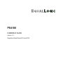
1
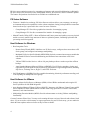
PS4100
Installation Guide
Version 1.0
Regulatory Model Series E03J and E04J
Copyright 2011 Dell, Inc. All rights reserved.
Dell is a trademark of Dell, Inc.
EqualLogic is a registered trademark.
All trademarks and registered trademarks mentioned herein are the property of their respective
owners.
Information in this document is subject to change without notice.
Reproduction in any manner whatsoever without the written permission of Dell is strictly forbidden.
June 2011
Part Number: 7V6V7 A00
Table of Contents
Preface ......................................................................................................................................................... v
1 Understanding the Array Installation Procedure.................................................................................. 1
2 Rack Mounting the Array........................................................................................................................ 3
Before You Begin .......................................................................................................................................................3
Installation Safety Precautions................................................................................................................................3
Rack Requirements .................................................................................................................................................3
Environmental Requirements..................................................................................................................................4
Protecting Hardware ...............................................................................................................................................4
Shipping Box Contents and Required Hardware ....................................................................................................5
Steps for Mounting an Array in a Rack ......................................................................................................................6
Installing the Rails and System in a Rack...............................................................................................................6
Determine Where to Place the Mounting Rails in the Rack ...................................................................................6
Slide the Chassis into the Rack ...............................................................................................................................6
Installing the Bezel..................................................................................................................................................7
3 Connecting the Array Cables .................................................................................................................. 9
Network Requirements and Recommendations ..........................................................................................................9
Minimum and Recommended Cable Configurations................................................................................................10
Connect and Secure the Power Cables......................................................................................................................11
Connect the Array to the Network ............................................................................................................................12
Turning On the Array............................................................................................................................................12
Set Up a Serial Connection to the Array...................................................................................................................13
Serial Cable Pinout Information ...........................................................................................................................14
4 Software Configuration.......................................................................................................................... 17
Choose a Configuration Method ...............................................................................................................................17
Collect Configuration Information............................................................................................................................17
Start the Software Configuration ..............................................................................................................................19
iii
PS4100 Installation Guide
Table of Contents
Using the setup Utility to Configure the Software................................................................................................19
Using the Remote Setup Wizard to Configure the Software ................................................................................20
Set the Member RAID Policy ...................................................................................................................................21
Using the CLI to Set the RAID Policy..................................................................................................................21
Using the GUI to Set the RAID Policy .................................................................................................................22
5 Storage Allocation................................................................................................................................... 25
Create a Volume........................................................................................................................................................25
Using the CLI to Create a Volume........................................................................................................................25
Using the GUI to Create a Volume .......................................................................................................................26
Connect a Computer to a Volume.............................................................................................................................28
6 Where to Go After Setting Up a Group................................................................................................ 31
Common Group Customization Tasks......................................................................................................................31
Advanced Group Administration Tasks....................................................................................................................32
7 Other Information You May Need........................................................................................................ 35
NOM Information (Mexico Only) ............................................................................................................................35
Technical Specifications
......................................................................................................................................35
Index............................................................................................................................................................ 39
iv
Preface
With one or more PS Series storage arrays, you can create a PS Series group—a self-managing, iSCSI
storage area network (SAN) that is affordable and easy to use, regardless of scale.
This manual describes how to install PS4100 array hardware, configure the software, and start using the
SAN.
Audience
The information in this guide is intended for the administrators responsible for installing array hardware.
Administrators are not required to have extensive network or storage system experience. However, it may
be helpful to understand:
• Basic networking concepts
• Current network environment
• User disk storage requirements
• RAID configurations
• Disk storage management
Note: Although this manual provides examples of using PS Series arrays in some common network
configurations, detailed information about setting up a network is beyond its scope.
Organization
This manual is organized as follows:
• Understanding the Array Installation Procedure on page 1 describes the general steps for installing and
setting up an array.
•
Rack Mounting the Array on page 3 describes how to install the array in a rack.
•
Connecting the Array Cables on page 9 describes the network cable requirements and how to install
the power and network cables.
• Software Configuration on page 17 describes how to initialize the array and either create a group with
the array as the first member, or add the array to an existing group.
• Storage Allocation on page 25 describes how to create and connect to a volume.
• Where to Go After Setting Up a Group on page 31 describes basic and advanced group administration
tasks and where to find information about them.
Overview of EqualLogic Products
Thank you for your interest in EqualLogic™ PS Series storage products. We hope you will find them
intuitive and simple to configure and manage.
v
PS4100 Installation Guide
Preface
PS Series arrays optimize resources by automating performance and network load balancing. Additionally,
PS Series arrays offer all-inclusive array management software, host software, and free firmware updates.
The features and products described next are available at no additional cost.
PS Series Software
• Firmware - Installed on each array, PS Series firmware software allows you to manage your storage
environment and provides capabilities such as volume snapshots, cloning, and replication to ensure data
hosted on the arrays is protected in the event of an error or disaster.
–
Group Manager GUI: Provides a graphical user interface for managing a group.
–
Group Manager CLI: Provides a command line interface for managing a group.
• Manual Transfer Utility (MTU) – Runs on Windows and Linux systems and enables you to use physical
media to securely transfer large amounts of data to a replication partner, facilitating replication and
preventing network congestion.
Host Software for Windows
• Host Integration Tools
–
Remote Setup Wizard (RSW): Initializes new PS Series arrays, configures host connections to PS
Series groups, and configures and manages multipathing.
–
Multipath I/O Device Specific Module (MPIO DSM): Includes a connection awareness-module that
understands PS Series network load balancing and facilitates host connections to PS Series
volumes.
–
VSS and VDS Provider Services: Allows 3rd party backup software vendors to perform off-host
backups.
–
Auto-Snapshot Manager/Microsoft Edition (ASM/ME): Uses PS Series snapshots, cloning, and
replication to provide point-in-time protection of critical data for supported applications, including
SQL Server, Exchange Server, Hyper-V, and NTFS file shares.
• SAN HeadQuarters (SANHQ): Provides centralized monitoring, historical performance trending, and
event reporting for multiple PS Series groups.
Host Software for VMware
• Storage Adapter for Site Recovery Manager (SRM): Allows SRM to understand and recognize PS
Series replication for full SRM integration.
• Auto-Snapshot Manager/VMware Edition (ASM/VE): Integrates with VMware Virtual Center and PS
Series snapshots to allow administrators to enable Smart Copy protection of Virtual Center folders,
datastores, and virtual machines.
• Multipathing Extension Module (MEM): Provides enhancements to existing VMware multipathing
functionality.
Current Customers Please Note: You may not be running the latest versions of the tools and software listed
above. If you are under a valid warranty or support agreement for your PS Series array, you are entitled to
obtain the latest updates and new releases as they become available.
vi
PS4100 Installation Guide
Preface
Related Documentation
For detailed information about PS Series arrays, groups, volumes, array software, and host software, see the
following documentation:
Technical Support and Customer Service
Dell’s support service is available to answer your questions about PS Series SAN arrays. If you have an
Express Service Code, have it ready when you call. The code helps Dell’s automated-support telephone
system direct your call more efficiently.
Contacting Dell
Dell provides several online and telephone-based support and service options. Availability varies by country
and product, and some services might not be available in your area.
vii
PS4100 Installation Guide
Preface
For customers in the United States, call 800-945-3355.
Note: If you do not have access to an Internet connection, contact information is printed on your invoice,
packing slip, bill, or Dell product catalog.
Use the following procedure to contact Dell for sales, technical support, or customer service issues:
1. Visit support.dell.com or the Dell support URL specified in information provided with the Dell product.
2. Select your locale. Use the locale menu or click on the link that specifies your country or region.
3. Select the required service. Click the “Contact Us” link, or select the Dell support service from the list
of services provided.
4. Choose your preferred method of contacting Dell support, such as e-mail or telephone.
Online Services
You can learn about Dell products and services using the following procedure:
1. Visit www.dell.com (or the URL specified in any Dell product information).
2. Use the locale menu or click on the link that specifies your country or region.
Warranty Information
The PS4100 array warranty is included in the shipping box. For information about registering a warranty,
visit support.dell.com/EqualLogic.
viii
1 Understanding the Array Installation Procedure
To set up a SAN and start using your array, follow these steps:
1. Install the array in a rack. See Rack Mounting the Array on page 3.
2. Connect the array to power and the network. See Connecting the Array Cables on page 9 and Connect
the Array to the Network on page 12.
3. Configure the PS Series software. First, initialize an array to make it accessible on the network. Then,
either create a group with the array as the first group member or add the array to an existing group. When
you expand a group, capacity and performance increase automatically. See Choose a Configuration
Method on page 17.
4. Start using the SAN. Allocate group storage space to users and applications by creating volumes. A
volume appears on the network as an iSCSI target. Use a computer’s iSCSI initiator to connect to a
volume. Once you connect to a volume, it appears as a regular disk on the computer. See Storage
Allocation on page 25.
After getting started, you can customize the group and use its more advanced features. See Where to Go
After Setting Up a Group on page 31.
1
2 Rack Mounting the Array
For proper operation, a PS Series storage array must be installed in a rack. This section contains general
electrostatic safety and network information, and installation information for PS Series arrays.
After installing the array in a rack, connect the power and network cables, as described in Connecting the
Array Cables on page 9.
Before You Begin
Before installing the array:
• Read the installation safety precautions. See Installation Safety Precautions.
• Make sure the rack meets the rack requirements. See Rack Requirements.
• Make sure the array and installation location meet the environmental requirements. See Environmental
Requirements on page 4.
• Unpack the rail kit (if ordered) and make sure you have all the necessary parts and tools. The rail kit is
located in the array shipping box. You must supply your own tools. See Shipping Box Contents and
Required Hardware on page 5.
Installation Safety Precautions
Follow these safety precautions:
• Dell recommends that only individuals with rack mounting experience install an array in a rack.
• Make sure the array is fully grounded at all times to prevent damage from electrostatic discharge.
• When handling the array hardware, you must use the electrostatic wrist guard shipped with the array or
a similar form of protection.
• You need at least two people to lift the array chassis from the shipping box.
Rack Requirements
Make sure the rack and the array installation meet the following requirements:
• Use an industry standard, EIA-310-D compliant, four-post 19 inch rack with universal square hole or
unthreaded round hole spacing.
• The rack must be rated for 540 kg (1200 pounds) static load or greater.
• The minimum rack depth is 100 cm (40 inches) from the front of the rack to the rear of the rack.
• The distance between the inside of the front and rear rack posts (the mounting surfaces) can range from
732 mm to 757 mm (28.8 inches to 29.8 inches) for RapidRails and from 708 mm to 757 mm (27.8
inches to 29.8 inches) for VersaRails.
• Secure the rack to the floor for added stability.
3
PS4100 Installation Guide
Rack Mounting the Array
• Load a rack with arrays from the bottom to the top.
• There must be at least 4.1 cm (1.6 inches) between the rack door and the front of the array to
accommodate the array front bezel.
• The rack (with installed arrays) must meet the safety requirements of UL 60950-1 and IEC 60950-1.
• Mount the array in a horizontal orientation, or you will void your array warranty and support contract.
Environmental Requirements
The rack location must meet the following environmental requirements:
• Only operate an array from a power source with a voltage range of 100 to 240 VAC.
• Make sure each power source has sufficient electrical overload protection.
• In North America, connect the array to a source of power with over-current protection provided by a
double pole 20A or less device (UL 489 circuit breakers). In Europe, the over-current protection must
be provided by a 20A or less device (IEC circuit breakers).
• Make sure there is sufficient space for air flow in front of and behind the array.
• Make sure the location is properly vented.
• Review the technical specifications in Technical Specifications on page 35 to make sure your
environment supports its requirements.
Protecting Hardware
Protect a PS Series array from electrostatic discharge. When handling array hardware, make sure you use
an electrostatic wrist strap or a similar form of protection.
To use a wrist strap:
1. Connect the steel snap on the coil cord to the stud on the elastic band. See Figure 1.
Figure 1 Using an Electrostatic Wrist Strap
2. Fit the band closely around your wrist.
3. Connect the banana plug to ground, or attach the plug to the alligator clip and connect the clip to a
grounded device such as an ESD mat or the metal frame of a grounded piece of equipment.
4
PS4100 Installation Guide
Rack Mounting the Array
Shipping Box Contents and Required Hardware
Make sure you have all the items supplied in the shipping box, described in Table 1. You must also provide
additional hardware that is specific to your environment and not included in the shipping box. See Table 2.
Table 1 Shipping Box Contents
Component
Description
PS Series Array
The array contains one or two Type 12 control modules.
The array also contains two power supply and cooling modules.
Bezel
Power cables
The PS4100 contains up to 12 3.5-inch or 24 2.5-inch Serial Attached SCSI
(SAS) drives, depending on the model suffix.
The bezel mounts to the front of the array. The bezel identifies the array model
and protects the drives from unauthorized or accidental removal.
Connects an array to power sources. The shipping box may contain different
types of power cables to meet the electrical requirements of the country in which
the array will reside. Use the cable type that is right for your environment.
If power cables are not included in the shipping box, contact your PS Series array
support provider or reseller.
One or two serial
Creates a serial connection between an array and a console or terminal emulator.
cables
Use the cable to run the setup utility or if there is no network access to the array
or group.
Rail assembly kit for a The shipping box will contain (if ordered with your array) either a Dell RapidRail
four-post rack (if
kit for square-hole racks or Dell Versa Rail kit (for round hole or tapped hole
ordered)
racks, for installation into a four-post rack. Follow the installation instructions
included with the kit.
Electrostatic wrist
Protects sensitive hardware from electrical discharge.
strap
Documentation
The following documentation is included in the shipping box:
• Setup poster
• Installation and Setup manual (this document)
• License, regulatory, and warranty information
Table 2 Additional Hardware (Not Included)
Component
Description
Standard 19 in. fourpost rack
10/100Mbps Ethernet
cables
Provides easy access to arrays and other hardware in your computing
environment.
For use with a dedicated management network. Connects the Management port
on the array to a 10/100Mbps network switch.
Network cables
Use Category 5E or Category 6 cables with RJ45 connectors. Use Category 5
cables only if they meet the TIA/EIA TSB95 standard.
Connects an array to a network switch. Use Category 5E or Category 6 cables
with RJ45 connectors. Use Category 5 cables only if they meet the TIA/EIA
TSB95 standard.
Connects devices to a network. Multiple switches are recommended.
Network switch
Optionally, you can also use an uninterruptible power supply system (UPS) to provide a highly available
source of power to an array. Each UPS (not included) should be on a different circuit and must provide the
5
PS4100 Installation Guide
Rack Mounting the Array
correct type of voltage for an adequate amount of time.
Steps for Mounting an Array in a Rack
Follow these steps to mount an array in a rack:
1. Determine where to place the mounting rails in the rack.
2. Attach the mounting rails to the rack.
3. Slide the chassis into the rack.
4. Attach the chassis to the front of the mounting rails.
5. Install the bezel.
These steps are described in detail in the following sections.
Installing the Rails and System in a Rack
Install the rails in the rack following the safety instructions and the rack installation instructions provided
with your rail kit.
If installed in a closed or multi-unit rack assembly, the operating ambient temperature of the rack
environment may be greater than room ambient. Therefore, make sure you install the equipment in an
environment compatible with the maximum ambient temperature (Tma) specified by the manufacturer. For
more information, see Technical Specifications on page 35.
Determine Where to Place the Mounting Rails in the Rack
Make sure there is enough space in the rack for the chassis. In a standard rack, a 2U chassis will span six
holes.
Slide the Chassis into the Rack
Figure 2 shows the front view of the 3.5-inch drive array.
Figure 2 3.5-Inch Drive Array - Front View (without Bezel)
Figure 3 shows the front view of the 2.5-inch drive array.
6
PS4100 Installation Guide
Rack Mounting the Array
Figure 3 2.5-Inch Drive Array - Front View (without Bezel)
Caution: Be careful when lifting the chassis.
1. With assistance, lift the chassis and slide it onto the mounting rails. Keep the chassis level.
2. Make sure the chassis captive fasteners on the front of the array line up with the threaded holes on the
front of the mounting rails, and manually secure the captive fasteners to the rails. Do not use an
automatic driver to tighten the thumbscrews.
Installing the Bezel
The steps for installing the bezel are the same for all the array models.
1. Hook the right end of the bezel onto the right side of the chassis.
2. Swing the left end of the bezel towards the left side of the chassis.
3. Press the bezel into place until the release latch closes.
4. Using the key provided, lock the bezel and store the key in a safe place.
7
3 Connecting the Array Cables
After you install the array in a rack, you must connect the network and power cables, and optionally, the
serial cable.
First, review the network recommendations in Minimum and Recommended Cable Configurations on page
10.
The following list describes the general steps for connecting the array to power and the network.
1. Connect the power cables. Do not turn on power to the array at this time. See Connect and Secure the
Power Cables on page 11.
2. Connect the array to the network. See Connect the Array to the Network on page 12.
3. Turn on power to the array. See Turning On the Array on page 12.
The following sections describe these steps in detail. After completing the steps, see Software Configuration
on page 17.
Network Requirements and Recommendations
The minimum network configuration for a PS Series array consists of a connection between Ethernet 0 on
each control module and a computer or a network switch. To increase performance and availability,
configure multiple network interfaces on an array and connect them to multiple switches.
Network recommendations are described in Table 3. In addition, all the usual rules for proper network
configuration apply to PS Series arrays. General network configuration is beyond the scope of this manual.
9
PS4100 Installation Guide
Connecting the Array Cables
Table 3 Network Recommendations
Recommendation
Description
Multiple network connections For increased bandwidth and availability, connect the Ethernet ports on
to different network switches both control modules to multiple network switches.
The switches must be connected using interswitch links. The links must
have sufficient bandwidth to handle the iSCSI traffic.
Management network
(optional)
Access to the group IP address
Redundant network paths
between computers and arrays
For replication, a reliable,
adequately sized network link
No STP functionality on
switch ports that connect end
nodes
After connecting the network interfaces, use the Group Manager GUI or
CLI to assign an IP address and netmask to each interface.
Optionally, connect the management ports on both control modules to a
10/100Mbps network switch to keep management traffic separate from
iSCSI traffic.
In a multi-subnet group, each configured network interface should have
access to the subnet on which the group IP address resides.
Use a multipathing solution to make sure that no single point of failure
exists between computers and arrays.
For effective and predictable replication, make sure that the network link
between the primary and secondary groups is reliable and provides
sufficient bandwidth for copying data.
If possible, do not use Spanning-Tree Protocol (STP) on switch ports
that connect end nodes (iSCSI initiators or array network interfaces).
However, if you must use STP or RSTP (preferable to STP), you should
enable the port settings (available on some switches) that let the port
immediately transition into STP forwarding state upon link up. This
functionality can reduce network interruptions that occur when devices
restart, and it should only be enabled on switch ports that connect end
nodes.
You can use Spanning-Tree for a single-cable connection between
switches, and you can use trunking for multi-cable connections between
switches.
Flow Control enabled on
Enable Flow Control on each switch port and NIC that handles iSCSI
switches and NICs
traffic. PS Series arrays will correctly respond to Flow Control.
Unicast storm control disabled Disable unicast storm control on each switch that handles iSCSI traffic
on switches
if the switch provides this feature. However, the use of broadcast and
multicast storm control is encouraged on switches.
Jumbo Frames enabled
Enable Jumbo Frames on each switch and each NIC that handles iSCSI
traffic.
VLANs
Configure switches to use VLANs to separate iSCSI SAN traffic from
other network traffic.
Minimum and Recommended Cable Configurations
For a single control module array, the minimum configuration is one network connection to Ethernet 0.
However, the single network connection is a potential point of failure. Dell recommends that you connect
all the available Ethernet ports to different network switches connected with interswitch links.
For a dual control module array, at a minimum, connect network cables to Ethernet 0 on both control
modules and then connect the cables to a network switch.
For maximum network bandwidth and availability, Dell recommends that you use four network cables to
10
PS4100 Installation Guide
Connecting the Array Cables
connect Ethernet 0 and Ethernet 1 on each control module to a different network switch. The switches must
be connected with interswitch links that have sufficient bandwidth. See Figure 4.
Figure 4 Recommended Network Configuration
Connect and Secure the Power Cables
Obtain the power cables that were shipped with the array. If the array was not shipped with power cables,
see your PS Series support provider or reseller for power cable information.
The power supply and cooling modules are the same in all PS4100 array models.
1. Make sure that the power switch is in the OFF position before connecting the power cables.
2. Connect the power cables to the system as shown in Figure 5.
3. Secure the cables firmly to the bracket using the provided hook-and-loop strap, as follows:
a. Make sure the strap is tightly bound to the anchor point (remove any slack).
b. Bias the power cord toward the strap and wrap the strap tightly around the cord against the shoulder
of the overmold.
4. Plug the other end of the power cables into a grounded electrical outlet or a separate power source such
as an uninterrupted power supply (UPS) or a power distribution unit (PDU).
Each UPS (not included) should be on a different circuit and must provide the correct type of voltage
for an adequate amount of time.
Alternately, connect one power supply and cooling module to a UPS system and connect the other
module to a different source of power.
Caution: Do not turn on power to the array yet.
11
PS4100 Installation Guide
Connecting the Array Cables
Figure 5 Connecting the Power Cables
Connect the Array to the Network
The PS4100 array model includes two Type 12 control modules. The Type 12 control module contains 2
1GB Ethernet ports, labeled Ethernet 0 and Ethernet 1.
The control modules also include one 10Mb/100Mb port labeled Management. The management port
cannot carry iSCSI traffic. Use the management port only if you configure a management network. See the
Group Administration manual for more information.
Obtain the appropriate number of Ethernet network cables.
One functioning network connection is required for array operation. Multiple network connections are
recommended for performance and high availability. See Minimum and Recommended Cable
Configurations on page 10 for additional information.
Turning On the Array
Before turning on power, allow sufficient time for the array to adjust to ambient temperature (for example,
overnight).
Note: You can turn on the power to one power supply first (either one), or both at the same time.
1. Find the power switch, located below the power plug on each power supply and cooling module.
2. Press the power switch to the ON position. The power indicators will light.
Batteries will start to charge and some hardware components will start to synchronize. LEDs will indicate
these normal activities.
See Figure 6 and Table 4.
12
PS4100 Installation Guide
Connecting the Array Cables
Figure 6 Power Supply LEDs
Table 4 Power Supply LED Descriptions
Callout
Description
1
Power Supply status. This LED is lit (green) when the switch is on and the power supply
is providing power to the array.
Error. This LED is lit (amber) if the power supply has a problem.
AC Power. This LED is lit (green) as long as mains power is connected to the power
supply.
2
3
Set Up a Serial Connection to the Array
If you plan to use the setup utility to configure the software, you must set up a serial connection between
the array and a computer. If you plan to use the Remote Setup Wizard, you do not need a serial connection.
See Choose a Configuration Method on page 17 for information about Remote Setup Wizard requirements.
The serial cable shipped with the array is a standard null-modem cable with a female DB9 connector on each
end. You might have to make or buy an adapter cable (one DB9 connector and one RJ45 connector) to
connect the array to some terminal server models. See Serial Cable Pinout Information on page 14 for more
information.
Attach the cable to the serial port on the active control module (ACT LED will be green) and to a console
terminal or a computer running a terminal emulator.
See Figure 7 (not to scale).
13
PS4100 Installation Guide
Connecting the Array Cables
Figure 7 Connecting a Serial Cable to the Array
The serial connection must have the following characteristics:
• 9600 baud
• One STOP bit
• No parity
• 8 data bits
• No flow control
Note: Keep the serial cable. You must use the serial cable to manage the group or a specific array if there
is no network access.
Serial Cable Pinout Information
Figure 8 shows the pin locations on the DB9 connectors on the serial cable shipped with the array, and Table
5 lists the pinout information for the cable.
Figure 8 Serial Cable DB9 Connector - Pin Locations
14
PS4100 Installation Guide
Connecting the Array Cables
Table 5 DB9 to DB9 Pinout Information
DB9-1
Function
Receive Data
Transmit Data
Data Terminal Ready
System Ground
Data Set Ready + Carrier Detect
Request to Send
Clear to Send
DB9-2
Pin
2
3
4
5
6+1
7
8
Pin
Function
3
2
6+1
5
4
8
7
Transmit Data
Receive Data
Data Set Ready + Carrier Detect
System Ground
Data Terminal Ready
Clear to Send
Request to Send
15
4 Software Configuration
After you complete the array hardware installation, you can initialize the array and create a PS Series group
with the array as the first group member. Alternately, you can add the array to an existing group. When you
expand a group, capacity and performance scale automatically with no impact on users.
After completing the software configuration, you can allocate storage and start using the SAN. See Storage
Allocation on page 25.
Choose a Configuration Method
There are two methods for configuring the software. Choose one method:
• Use the Remote Setup Wizard, either for Windows or Linux. See the Host Integration Tools
documentation for instructions and requirements.
• Use the setup utility. The setup utility is an interactive, command line utility that prompts for
information about the array and group configuration.
To use the setup utility, you must have a serial connection between the array and a console terminal or a
computer running a terminal emulator.
After choosing a method, collect the information needed for the array configuration.
Collect Configuration Information
Regardless of the method you use to configure the software, you must collect the information in Table 6 and
Table 7. Obtain IP addresses from your network administrator, as needed.
Also, make sure you follow the network recommendations in Network Requirements and Recommendations
on page 9.
17
PS4100 Installation Guide
Software Configuration
Table 6 Array Configuration Information
Prompt
Description
Member name
Unique name for the array in the group (63 or fewer letters, numbers, or
hyphens). First character must be a letter or number.
Name of a network interface on the array (eth0 or eth1) that is connected to a
functioning port on a network switch.
Network address for the array network interface.
Note: Each member must have at least one network interface on the same subnet as the group IP address.
Address that combines with the IP address to identify the subnet on which the
array network interface resides (default is 255.255.255.0).
Network address for the device used to connect subnets and forward network
traffic beyond the local network. A default gateway is needed only if you want
the array network interface to communicate outside the local network (for
example, to allow access to volumes from computers outside the local network).
Note: The default gateway must be on the same subnet as the array network
interface.
Network interface
IP address
Netmask
Default gateway
(optional)
RAID policy
RAID level and spare drive configuration for the array. The actual number of
RAID sets and spare drives depends on the number of drives in the array.
• RAID 10 – Striping on top of multiple RAID 1 (mirrored) sets.
• RAID 50 – Striping on top of multiple RAID 5 (distributed-parity) sets.
Each RAID 5 set uses one drive's worth of space for parity.
• RAID 5 – Distributed-parity sets.
• RAID 6 – Multiple dual distributed-parity sets.
• RAID 6 Accelerated – Only available on XS and XVS array models.
Table 7 Group Configuration Information
Prompt
Description
Group name
Unique name that identifies the group (54 or fewer letters, numbers, or hyphens).
The first character must be a letter or number.
Network address for the group. The group IP address is used for group
administration and computer access to data stored in the group.
Password required when adding members to a group. The password must have 3
to 16 letters or numbers and is case-sensitive.
Group IP address
Password for adding
members to a group
Password for the
grpadmin account
Password that will override the factory-set group administration password
(grpadmin) for the grpadmin account. The password must have 3 to 16 letters or
numbers and is case-sensitive.
Required only when creating a new group.
Microsoft service user CHAP user name and password used to enable Microsoft service (VSS or VDS)
name and password access to the group. The user name must have 3 to 63 alphanumeric characters.
(optional)
The password must have 12 to 16 alphanumeric characters, and is case-sensitive.
Microsoft services running on a computer must be allowed access to the group
in order to create VSS snapshots in the group or use VDS.
Applicable only when creating a group with the Remote Setup Wizard.
18
PS4100 Installation Guide
Software Configuration
Start the Software Configuration
Use the setup utility or the Remote Setup Wizard to initialize the array and either create a group with the
array as the first group member or add the array to an existing group.
After you complete the software configuration, the array becomes a member of a group and its disk storage
is available for use.
Using the setup Utility to Configure the Software
To use the setup utility to initialize an array and create or expand a group:
1. On the console or terminal emulator that has the serial connection to the array, press the Enter key.
Note: If the array does not respond, contact your PS Series support provider for information on how
to proceed.
2. At the login prompt, enter grpadmin for both the account (login) name and the password. Passwords do
not appear on the screen.
3. When prompted, enter y to start the setup utility.
4. When prompted, enter the array and group configuration information from Collect Configuration
Information on page 17. Press the Enter key to accept a default value. Enter a question mark (?) to get
help.
Specify whether to create a group with the array as the first member or add the array to an existing
group.
Note: There may be a short delay after entering the group IP address as the array searches the network.
After setup completes, you must set the member’s RAID policy in order to use the disk storage. Go to Set
the Member RAID Policy on page 21.
The following example shows using the setup utility to initialize an array and create a group.
EXAMPLE - Using the setup Utility
Login: grpadmin
Password: xxxxxxxx
The setup utility establishes the initial network and storage configuration for a storage
array and then configures the array
as a member or a new or existing group of arrays.
For help, enter a question mark (?) at a prompt.
Welcome to Group Manager
Copyright 2011 Dell, Inc.
It appears that the storage array has not been configured.
Would you like to configure the array now? (y/n) [n] y
Group Manager Setup Utility
Do you want to proceed (yes | no) [no]? yes
Initializing. This may take several minutes to complete.
Enter the network configuration for the array:
Member name []: member1
19
PS4100 Installation Guide
Software Configuration
Network interface [eth0]: eth0
IP address for network interface []: 192.17.2.41
Netmask [255.255.255.0]:
Default gateway [192.17.2.1]:
Enter the name and IP address of the group that the array will join.
Group name []: group1
Group IP address []: 192.17.2.20
Searching to see if the group exists. This may take a few minutes.
The group does not exist or currently cannot be reached. Make sure you have entered the
correct group IP address and group name.
Do you want to create a new group (yes | no) [yes]? yes
Group Configuration
Group Name: group1
Group IP address: 192.17.2.20
Do you want to use the group settings shown above (yes | no) [yes]: yes
Password for managing group membership:
Retype password for verification:
Password for the default group administration account:
Retype password for verification:
Saving the configuration ...
Waiting for configuration to become active......Done
Group member member1 now active in the group.
Group group1 has been created with one member.
Use the Group Manager GUI or CLI to set the RAID policy for the member. You can then
create a volume that a host can connect to using an iSCSI initiator.
group1>
Using the Remote Setup Wizard to Configure the Software
The Remote Setup wizard is located on the Host Integration Tools CD-ROM and must be installed on a
Windows computer. The Host Integration Tools User Guide provides detailed information about using the
full capabilities of the Remote Setup Wizard.
To run the Remote Setup Wizard, follow these steps:
1. Use a computer that meets the requirements in Choose a Configuration Method on page 17.
2. Obtain the Host Integration Tools CD-ROM from the shipping box, or download the Host Integration
Tools kit from the support website.
3. Install the Remote Setup Wizard following the instructions in the Host Integration Tools documentation.
4. Start the Remote Setup Wizard by clicking:
Start, Programs, EqualLogic, Remote Setup Wizard
5. In the Welcome dialog box, select Initialize a PS Series array and click Next.
Note: If you cannot contact the array, check the network configuration. You may need to use the setup
utility to configure the software.
6. Select the array that you want to initialize and click Next.
7. In the Initialize Array dialog box, enter the array configuration from Table 6 and choose to create a
group or join an existing group. Then, click Next.
20
PS4100 Installation Guide
Software Configuration
8. In the Create a New Group or Join an Existing Group dialog box, enter the group configuration from
Table 7 and click Next.
9. Click Finish to exit the wizard.
If you added the array to an existing group, you must set the member’s RAID policy in order to use the disk
storage. Go to Set the Member RAID Policy.
If you created a new group, go to Storage Allocation on page 25.
Set the Member RAID Policy
The storage space in a new group member (array) is not available until you configure a RAID policy on the
member. A RAID policy consists of a RAID level and a spare disk configuration. When you select a RAID
policy, the member’s disks are automatically configured with the selected RAID level and the appropriate
number of spare disks.
If you used the Remote Setup Wizard to create a group, the RAID policy for the first member is set
according to your RAID policy selection when configuring the software, and the storage is ready to use. See
Storage Allocation on page 25.
If you used the setup utility to create or expand a group, or added the array to an existing group with the
Remote Setup Wizard, you must set the RAID policy for the group member.
Use either the Group Manager command line interface (CLI) or the graphical user interface (GUI) to set the
RAID policy.
Using the CLI to Set the RAID Policy
To use the Group Manager CLI to set the RAID policy for a new group member:
1. Log in to the group, if you are not already logged in. (After the setup utility completes, you will still be
logged in to the group.)
Use one of the following methods to connect to the group:
–
Serial connection to a member. See Set Up a Serial Connection to the Array on page 13.
–
Telnet or ssh connection to the group IP address.
2. At the login prompt, enter the grpadmin account name and the password that you specified when
creating the group.
3. At the Group Manager command prompt, enter the following command, specifying raid50, raid5,
raid10, raid6, or raid6-accelerated (only available XS array models) for the policy variable:
member select member_name raid-policy policy
For example, the following command configures member1 with RAID50:
group1> member select member1 raid-policy raid50
21
PS4100 Installation Guide
Software Configuration
Using the GUI to Set the RAID Policy
For the latest information on browser support for the Group Manager GUI, see the PS Series Release Notes.
To use the GUI to set the RAID policy for a member:
1. Log in to the group by entering the group IP address in a Web browser. Then, in the login dialog box
(Figure 9), enter the grpadmin account name and the password that you specified when creating the
group.
Figure 9 GUI Login
2. In the Group Summary window (Figure 10), expand Members in the far left panel and select the member
name.
Figure 10 Group Summary – RAID Policy Is Not Set on Member
3. In the warning message dialog box that appears, click Yes to configure RAID on the member.
22
PS4100 Installation Guide
Software Configuration
4. In the Configure Member – General Settings dialog box (Figure 11), click Next.
Figure 11 Configure Member – General Settings
5. In the Configure Member – RAID Configuration dialog box (Figure 12), do the following and then click
Next.
a. Select the RAID policy.
b. Optionally, to delay using the member’s storage space until the RAID verification completes and
the batteries are fully charged, select Wait until the member storage initialization completes. By default, the space is immediately available, although performance will not be optimal
until the RAID verification completes.
Figure 12 Configure Member – RAID Configuration
6. In the Configure Member – Summary dialog box (Figure 13), click Finish if the member configuration
is satisfactory. Click Back to make changes.
23
PS4100 Installation Guide
Software Configuration
Figure 13 Configure Member – Summary
The array storage is ready to use.
24
5 Storage Allocation
Allocating group storage space to users involves the following steps:
1. Create a Volume.
2. Connect a Computer to a Volume on page 28.
After allocating storage, you can customize the group and use its more advanced features. See Where to Go
After Setting Up a Group on page 31.
Create a Volume
To allocate group storage space to users and applications, use the Group Manager CLI or GUI to create
volumes. A volume appears on the network as an iSCSI target. When you create a volume, specify the
information described in Table 8.
Table 8 Volume Configuration Information
Component
Description
Volume name
This is a unique name, 63 or fewer characters (including letters, numbers,
periods, hyphens, and colons). The volume name is appended to the end of the
iSCSI target name, which is automatically generated for the volume. Access to a
volume is always through the target name.
This is the reported size of the volume as seen by iSCSI initiators. The minimum
volume size is 15 MB. Volume sizes are rounded up to the next multiple of 15
MB.
Allows computer access to a volume. A computer can access a volume only if it
matches the security credentials in a record:
• iSCSI initiator – Restricts access to the specified initiator name.
• IP address – Restricts access to iSCSI initiators with the specified initiator IP
address. Use asterisks for wildcards, if desired (for example, 12.16.*.*). An
asterisk can replace an entire octet, but it cannot replace a digit within an
octet.
Volume size
Access controls
At a later time, you can configure CHAP accounts in the group and use the
accounts in access control records to restrict access to volumes. See the Group
Administration manual for information.
Also specify read-write or read-only access for the volume.
Optionally, you can set aside space for volume snapshots or configure a volume with thin provisioning.
However, thin provisioning is not appropriate for all storage environments. See the PS Series Group
Administration manual for information about advanced volume functionality.
Using the CLI to Create a Volume
1. Log in to the group.
Use one of these methods to connect to the group:
25
PS4100 Installation Guide
Storage Allocation
–
Serial connection to a member. See Set Up a Serial Connection to the Array on page 13.
–
Telnet or ssh connection to the group IP address.
At the login prompt, enter the grpadmin account name and the password that you specified when
creating the group.
2. At the Group Manager command prompt, use the following command to create the volume:
volume create volume_name size [GB]
Specify the volume name and size (the default unit of measure is megabytes).
3. Use the following command to create an access control record for the volume:
volume select volume_name access create access_control
The access_control parameter can be one or more of the following:
•
initiator initiator_name
•
ipaddress ip_address
You can create a maximum of 16 access control records for a volume.
The following example creates a 50 GB volume and one access control record. Only a computer with the
specified initiator name will be able to access the volume.
group1> volume create staff1 50GB
group1> volume select staff1 access create initiator iqn.199105.com.microsoft:WIN2008Server.company.com
Using the GUI to Create a Volume
1. Log in to the group.
Specify the group IP address in a Web browser. Then, in the login dialog box, enter the grpadmin
account name and the password that you specified when creating the group.
2. In the Group Summary window, click Create volume in the Activities panel.
3. Enter the volume name and an optional description (Figure 14), and click Next.
26
PS4100 Installation Guide
Storage Allocation
Figure 14 Create Volume – General Properties
4. Enter the volume size (Figure 15) and click Next. The table values will reflect the size you specify.
Figure 15 Create Volume – Space Reserve
5. Specify the iSCSI initiator name or IP address for the access control record (Figure 16) and click Next.
27
PS4100 Installation Guide
Storage Allocation
Figure 16 Create Volume – iSCSI Access
6. Review the summary information (Figure 17) and click Finish if the volume configuration is correct.
Click Back to make changes.
Figure 17 Create Volume – Summary
Connect a Computer to a Volume
When you create a volume, the PS Series group automatically generates an iSCSI target name, with the
volume name appended to the end of the target name. Each volume appears on the network as an iSCSI
target.
An example of an iSCSI target name for a volume named dbvol is as follows:
iqn.2001-05.com.equallogic.5-4a0900-2f00000-007eca92d654f160-dbvol
To connect a computer to a volume:
28
PS4100 Installation Guide
Storage Allocation
1. Install and configure an iSCSI initiator on the computer. Hardware and software initiators are available
from different vendors. Configure your initiator using the instructions provided by the vendor.
Note: Dell recommends that you visit the Technical Support website to obtain important information
about using initiators to access PS Series group volumes.
2. Make sure that the computer matches one of the volume’s access control records. To display the records
for a volume:
–
Using the CLI, enter the following command:
volume select volume_name access show
–
Using the GUI, expand Volumes in the far-left panel, select the volume name, and click the Access
tab.
If necessary, use the CLI or the GUI to create an access control record that the computer will match.
3. To display the iSCSI target name for the volume:
–
Using the CLI, enter the following command:
volume select volume_name show
–
Using the GUI, expand Volumes in the far-left panel, select the volume name, and click the
tab.
Connections
4. On the computer, use the iSCSI initiator utility to specify the group IP address as the iSCSI discovery
address. If the initiator supports the discovery process, it will return a list of iSCSI targets that the computer can access.
If the initiator does not support discovery, you must also specify the target name, and, in some cases,
the standard iSCSI port number (3260).
5. Use the iSCSI initiator utility to select the desired target and log in to the target.
When the computer connects to the iSCSI target, it sees the volume as a regular disk that can be formatted
using the normal operating system utilities. For example, you can partition the disk and create a file system.
29
6 Where to Go After Setting Up a Group
After setting up a group, you can customize the group in order to more effectively manage your storage
environment. You can also begin to use the full set of product features. The following documentation and
additional products are included in the purchase of your array and available at any time.
• The PS Series Group Administration manual provides details on storage concepts and how to use the
Group Manager GUI to manage a group.
• The PS Series CLI Reference manual describes how to use the Group Manager CLI to manage a group
and individual arrays.
• The Manual Transfer Utility supports off-network replication of volume data.
• In a VMware environment, you can use the Auto-Snapshot Manager/VMware Edition to manage
snapshots and replicas on the PS group that can restore individual virtual machines or the whole
VMware environment.
• You can use the Storage Adapter for Site Recovery Manager (SRM), which allows SRM to understand
and recognize PS Series replicas for full SRM integration.
• The Multipathing Extension Module (MEM) provides enhancements to the VMware multipathing
functionality.
• In a Microsoft environment, you can use the Auto-Snapshot Manager/Microsoft Edition to manage
snapshots and replicas on the PS group that can restore applications such as SQL Server, Exchange
Server, Hyper-V, and NTFS file shares.
• If you have several PS Series groups, you can monitor and manage them with the SAN HeadQuarters
(SANHQ) utility.
Common Group Customization Tasks
Table 9 describes the common group customization tasks. These tasks are fully documented in the PS Series
Group Administration manual.
31
PS4100 Installation Guide
Where to Go After Setting Up a Group
Table 9 Common Group Customization Tasks
Task
Description
Add network connections to a Multiple network connections increase performance and availability and
group member
are required for multipath I/O. Dell recommends that you connect all the
network interfaces on both control modules to multiple network
switches and then use the GUI or CLI to assign an IP address and
netmask to the interfaces.
Create administration
accounts
The grpadmin account is the default administration account. Dell
recommends you set up additional accounts for each administrator, and
reserve the default grpadmin account for maintenance operations such
as firmware upgrades.
Accounts can be configured to be authenticated through the PS Series
group, or using LDAP or Active Directory authentication.
Set up event notification
To be informed of significant events in a timely manner, set up e-mail or
syslog notification.
Configure SNMP
To monitor traps from the group, you can use SNMP. In addition, you
need to configure SNMP to use the Manual Transfer Utility and other
third-party monitoring tools.
Configure iSNS
To automate iSCSI target discovery, you can configure the group to use
an iSNS server.
Configure CHAP accounts
You can use CHAP to restrict computer access to volumes. Both initiator
and target CHAP authentication are supported.
Modify the date, time, or time Group time is based on the clock on the first member, which is set at the
zone or configure NTP
factory. The default time zone is EST. You can also configure the group
to use an NTP server.
Advanced Group Administration Tasks
Table 10 describes the advanced group administration tasks. These tasks are fully documented in the PS
Series Group Administration manual.
Table 10 Advanced Administration Tasks
Task
Description
Add a member to the group
Although a one-member group is fully functional, adding more arrays
expands capacity, increases network bandwidth, and improves overall
group performance, with no disruption to data availability.
Create pools
With multi-member groups, you can create multiple pools and assign
members and volumes to the pools for a tiered storage solution.
Set up a dedicated
You can set up a separate management network for security purposes.
management network
Create snapshots of a volume Snapshots are point-in-time copies of volume data that can be used for
backups.
Create schedules for snapshots Schedules enable you to regularly create snapshots or replicas of a
or replicas
volume.
32
PS4100 Installation Guide
Where to Go After Setting Up a Group
Task
Description
Create collections
Collections enable you to group multiple, related volumes for the
purpose of creating snapshots or replicas. The administrator can then
create a multi-volume snapshot or a multi-volume replica in a single
operation or through a single schedule.
Enable thin provisioning for a Some environments can benefit from thin provisioning, which enables
volume
you to allocate space to a volume according to usage patterns.
Set up replication across
different groups
Clone a volume or snapshot
Replicas are point-in-time copies of volume data that are stored on a
different group.
Cloning creates a new volume in the group.
Recover data from snapshots There are various options for recovering data from snapshots or replicas.
or replicas
33
7 Other Information You May Need
See the safety and regulatory information that shipped with your system. Warranty information may be
included within this document or as a separate document.
• The rack documentation included with your rack solution describes how to install your system into a
rack.
• The Hardware Maintenance Manual provides information about system features and describes how to
troubleshoot the system and install or replace system components. This document is available online at
support.dell.com.
NOM Information (Mexico Only)
The following information is provided on the device described in this document in compliance with the
requirements of the official Mexican standards (NOM):
Importer
Dell México S.A. de C.V.
Paseo de la Reforma 2620 -- 11° Piso
Col. Lomas Altas
11950 México, D.F.
Model number: E03J
Supply voltage: 100–240 VAC
Frequency: 50/60 Hz
Current consumption: 8.6A
Model number: E04J
Supply voltage: 100–240 VAC
Frequency: 50/60 Hz
Current consumption: 8.6A
Technical Specifications
Power Supplies
AC power supply (per power supply)
Wattage
PS4100 (all suffixes):
• 700 W (max, total)
• +5V up to 155W; +12V up to 624W; +5Vsb up to 10W
Voltage
100–240 VAC (8.6 A–4.3 A)
Heat dissipation
188 W
Input frequency
50/60 Hz
Max input power
990KVA
Input current
11A@90VAC
Maximum inrush
current
Under typical line conditions and over the entire system ambient operating range,
the inrush current may reach 55A per power supply for 10 ms or less.
35
PS4100 Installation Guide
Other Information You May Need
Physical
Height
8.68 cm (3.41 inches)
Width
44.63 cm (17.57 inches)
Depth
PS4100E, XV (3.5-inch drives): 59.4 cm (23.4 inches)
PS4100X, XV (2.5-inch drives): 54.1 cm (21.3 inches)
Weight (fully loaded
array)
PS4100E, XV (3.5-inch drives): 26.76 kg (59 lb)
PS4100X, XV (2.5-inch drives): 24.49 kg (54 lb)
Available Hard Drive Power (Per Slot)
Supported hard drive power consumption (continuous)
For 2.5-inch drives:
• Up to 1.2A at +5V
• Up to 0.5A at +12V
For 3.5-inch drives:
• Up to 1.16A at +5V
• Up to 1.6A at +12V
Environmental
Operating temperature
5° to 40°C (41° to 104°F) with a maximum temperature gradation of 10°C
per hour
Note: For altitudes above 2950 feet, the maximum operating
temperature is derated 1ºF/550 ft.
Storage temperature
–40° to 65°C (–40° to 149°F) with a maximum temperature gradation of
20°C per hour
Operating relative humidity
20% to 80% (noncondensing) with a maximum humidity gradation of
10% per hour
Storage relative humidity
5% to 95% (noncondensing)
Operating vibration
0.26 Grms (5 to 350 Hz) for 5 minutes in operational orientations only
Storage vibration
1.88 Grms (10 to 500 Hz) for 15 minutes (all 6 sides)
Operating shock
Half-sine shock 31G +/- 5% with a pulse duration of 2.6ms +/- 10% in
operational orientations only
Storage shock
• Half-sine shock 71G +/- 5% with a pulse duration of 2ms +/- 10% (all
6 sides)
• Square wave shock 27G with a velocity change of 235 in/sec (all 6
sides)
Operating altitude
–16 to 3048 m (–50 to 10,000 ft)
Note: For altitudes above 2950 feet, the maximum operating
temperature is derated 1ºF/550 ft.
Storage altitude
–16 to 10,600 m (–50 to 35,000 ft)
Airborne contaminant level
Class G2 or lower as defined by ISA-S71.04-1985
36
PS4100 Installation Guide
37
Other Information You May Need
Index
access controls
electrostatic wrist strap, using ..........4
protecting volumes .......................25
environmental requirements .............4
setting up with CLI ......................26
event notification, configuring .......32
setting up with GUI ......................27
Flow Control recommendation .......10
accounts, configuring after setup ....32
array
group
accessing volumes ........................29
choosing where to mount ...............6
advanced tasks ..............................31
initializing ....................................17
creating .........................................17
mounting in rack ............................6
customizing after setup ................31
network address ...........................18
expanding .....................................17
RAID policy .................................21
IP address .....................................18
software configuration .................17
logging in to CLI ..........................21
bezel
installing .........................................7
cables
logging in to GUI .........................22
name .............................................18
GUI
Ethernet ..........................................5
creating volumes ..........................26
CHAP accounts, configuring ..........32
setting RAID policy ...............21–22
CLI
hardware
creating volumes ..........................25
requirements ...................................5
setting RAID policy .....................21
supplied ..........................................5
connecting the serial cable ..............13
Host Integration Tools, description 20
control modules ................................5
hosts
date, setting .....................................32
Flow Control recommendation ....10
electrostatic discharge, avoiding .......4
Jumbo Frames recommendation ..10
39
PS4100 Installation Guide
Index
installation safety precautions ...........3
NTP server, configuring ................. 32
installing
power requirements .......................... 4
front bezel ......................................7
iSNS, configuring ...........................32
power, turning on ........................... 12
PS Series array
Jumbo Frames recommendation .....10
increasing bandwidth ................... 10
login
multipath I/O recommendation .... 10
CLI method ..................................21
network recommendations ....... 9–10
GUI method ..................................22
network requirements .............. 9–10
management network switch ............5
protecting from discharge .............. 4
member
subnet access recommendation .... 10
default gateway ............................18
rack mount
naming ..........................................18
choosing rail location ..................... 6
netmask ........................................18
inserting chassis ............................. 6
network address ............................18
installing chassis ............................ 6
RAID policy .................................21
rail kit parts .................................... 5
netmask, member setting ................18
requirements .................................. 3
network
array IP address ............................18
RAID levels, supported .................. 21
RAID policy
configuring multiple interfaces ....32
description ................................... 21
group IP address ...........................18
setting with CLI ........................... 21
improving performance ................10
setting with GUI .......................... 22
recommendations .....................9–10
Remote Setup Wizard
requirements .............................9–10
configuring the software .............. 20
network cables ................................12
safety precautions, installation ......... 3
network interfaces
serial cable
configuring ...................................18
40
characteristics .............................. 14
PS4100 Installation Guide
pin locations .................................14
Index
target (iSCSI)
pinout information ........................15
obtaining name ............................ 29
serial cable, connecting ...................13
technical specifications .............. 4, 35
setup utility
thin provisioning, enabling ............. 25
configuring the software ..............19
time, setting .................................... 32
description ....................................17
unicast storm control ...................... 10
requirements .................................17
VLAN recommendation ................. 10
shipping box contents .......................5
volumes .......................................... 25
snapshots, reserving space ..............25
access controls ............................. 25
SNMP, configuring .........................32
accessing ...................................... 29
software configuration, methods ....17
connecting to ................................ 28
Spanning-Tree recommendation .....10
creating ........................................ 25
supplied hardware .............................5
creating with CLI ......................... 25
switch
creating with GUI ........................ 26
for management only .....................5
switches
naming ......................................... 25
reported size ................................. 25
10/100Mbps ...................................5
snapshot space ............................. 25
bandwidth requirement ................10
target name for ............................. 29
Flow Control recommendation ....10
thin provisioning settings ............. 25
Jumbo Frames recommendation ..10
warranty .......................................... 35
link recommendation ....................10
Spanning-Tree recommendation ..10
unicast storm control ....................10
VLAN recommendation ...............10
system
specifications ................................35
41