1
©
®
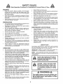
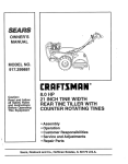
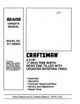
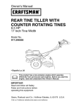
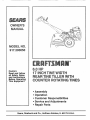
6.0 HP
17 iNCH TINE WIDTH
TU TULLER WiTH
COUNTER F_OTATI
TIN
Caution:
Read and follow
all Safety Rules
and instructions
Before Operating
This Equipment
®Assembly
- Operation
Customer Responsibilities
o Service and Adjustments
, Repa_r Parts
i iii
,, i
i i
Sears, Roebuck
i,
ii
,, iii
.................................
and Co., Hoffman
i
Estates,
,1111,1,,111,,111111,,i,i
IL 60179 U.S.A.
SAFETY RULES
Safe Operation
Practices
for Walk-Behind
TRAINING
,
•
•
Read the Owner's Manual carefulty_ Be thoroughly
familiar with the controls and the proper use of the
equipment. Know how to stop the unit and disengage
the controls quickly
Never allow children to operate the equipment.. Never
allow adutts to operate the equipment without proper
instruction
Keep the area of operation clear of all persons, particularly small children, and pets.
PREPARATION
•
•
•
•
•
.
.
o
•
Thoroughly inspect the area where the equipment is to
be used and remove all foreign objects°
Disengage all clutches and shift into neutral before
starting the engine (motor).
Do not operate the equipment without wearing adequate outer garments.r Wear footwear that will improve footing on slippery surfaces°
Handle fuel with care; it is highly flammable
Use an approved fuel container.
Never add fuel to a running engine or hot engine
Fill fuel tank outdoors with extreme care. Never fi!I fuel
tank indoors.
Replace gasoline cap securely and ciean up spilled
fuel before restarting.
Use extension cords and receptacles as specified by
the manufacturer for all units with electric drive motors
or electric starting motors.
Never attempt to make any adjustments while the
engine (motor) is running (except where specifically
recommended by manufacturer).
=
•
Powered
Rotary
Tillers
Keep children and pets away
Do not overload the machine capacity by attempting to
till too deep at too fast a rate.
Never operate the maclqine at high speeds on slippery
surfaces. Look behind and use care when backing.
Never allow bystanders near the unit
Use only attachments and accessories approved by
the manufacturer of the tiller (such as wheel weights,
counterweights, cabs, and the like).
Never operate the tiller without good visibility or light
Be careful when tilling in hard ground. The tines may
catch in the ground and propel the tiller forward, If this
occurs, tet go of the handlebars and do not restrain the
machine
•
•
o
.
•
MAINTENANCE
°
AND STORAGE
Keep machine, attachments, and accessories in safe
working condition.
Check shear pins, engine mounting bolts, and other
bolts at frequent intervals for proper tightness to be
sure the equipment is in safe working condition.
Never store the machine with fuel in the fuel tank inside
a building where ignition sources are present, such as
hot water and space heaters, clothes dryers, and the
like. Allow the engine to cool before storing in any
enclosure.
Atways refer to the operator's guide instructions for
important details if the tiller is to be stored for an
extended period.
-
o
- IMPORTANT-
OPERATION
CAUTIONS, IMPORTANTS, AND NOTES ARE A MEANS
OF ATTRACTING ATTENTION TO IMPORTANT OR
CRITICAL INFORMATION IN THIS MANUAL
o
=
IMPORTANT: USED TO ALERT YOU THAT THERE ISA
POSSIBILITY OF DAMAGING THIS EQUIPMENT.
-
°
•
•
o
°
.
.
Do not put hands or feet near or under rotating parts.
Exercise extreme caution when operating on or crossing gravel drives, walks, or roads, Stay alert for hidden
hazards or traffic, Do not carry passengers.
After striking a foreign object, stop the engine (motor),
remove the wire from the spark plug, thoroughly inspect the tiller for any damage, and repair the damage
before restarting and operating the tiller
Exercise caution to avoid slipping or falling
If the unit should start to vibrate abnormally, stop the
engine (motor) and check immediately for the cause
Vibration is generally a warning of trouble
Stop the engine (motor) when leaving the operating
position,
Take all possible precautions when leaving the machine unattended.
Disengage the tines, shift into
neutral, and stop the engine.
Before cleaning, repairing, or inspecting, shut off the
engine and make certain all moving parts have stopped.
Disconnect the spark plug wire, and keep the wire
away from the plug to prevent accidental starting,
Disconnect the cord on electric motors.
Do not run the engine indoors; exhaust fumes are
dangerous,
Never operate the tiller without proper guards, plates,
or other safety protective devices in place,
NOTE:
Gives essential information that witl aid you to
better understand, incorporate, or execute a particular set
of instructions,.
i, ,,Ul
i , i , lu ,,UllllUr,_l
t ,_
I _
I _
I
,
,,,,
......
Look for this symbol to point out important safety precautions.
It means
CAUTION!!! BECOMEALERT!!!
YOUR
SAFETY IS INVOLVED
u
, i
ii
u i,
i,i1_1i,Ulllllll
,,,,,,,,,,,,,,,,,,,,,,,
plug
wire andAlways
place wire
where
CAUTION:
disconnect
not contact spark plug in order
vent accidental starting when
up, transporting,
adjusting or
repairs.
i,UUlll
ii,
i
itspark
canto presetting
making
,,Ul,i,
WARNING
...........
The engine
exhaust from this product contains chemicals known to the State of .California to cause cancer,
birth defects,
or other
reproductive
harm.
u,
i ilur Ullll,, iii ......
i,,
ii,u,,
PRODUCT
CONGRATULATIONS
on your purchase of a Sears Tiller,
It has been designed, engineered and manufactured to
give you the best possible dependability and performance.
Should you experience any problems you cannot easily
remedy, pfease contact your' nearest authorized Sears
Service Center/Department.
They have competent, welF
trained technicians and the proper tools to service or repair
this unit.
SPECIFICATIONS
HORSEPOWER:
6,0 HP
DISPLACEMENT:
11.88 cu_ino(195cc)
GASOLINE CAPACITY:
4 Quarts
Unleaded Regular
PIease read and retain this manual The instructions will
enable you to assemble and maintain your tiller' propedy
Always observe the "SAFETY RULES",
I
i OIL (API-SF/SG) :
(CAPACITY: 20 oz.)
SAE 30 (Above 32°F)
SAE 5W-30 (Befow 32°F)
SPARK PLUG :
MODEL
NUMBER
Champion
RN4C
(GAP: 030")
917.293650
SERIAL
NUMBER
MAINTENANCE
DATE OF
PURCHASE
A Sears Maintenance Agreement is available on this product. Contact your nearest Sears store for details.
CUSTOMER
THE MODEL AND SERIAL NUMBERS WILL BE
FOUND ON THE MODEL PLATE ATTACHED TO
THE TOP OF THE TRANSMISSION,
YOU SHOULD RECORD BOTHSERIALNUMBER
AND DATE OF PURCHASE AND KEEPIN A SAFE
PLACE FOR FUTURE REFERENCE.
AGREEMENT
RESPONSIBILITIES
°
Read and observe the safety rules.
o
Follow a regular schedule in maintaining, caring for and
using your tiller.
Follow the instructions
under the "Customer
Responsibilities" and "Storage" sections of this Owner's
Manual..
o
IMPORTANT:
THIS UNIT IS EQUIPPED WITH AN INTERNAL COMBUSTION
ENGINE AND SHOULD t_OT BE USED ON
OR NEAR ANY UNIMPROVED
FOREST-COVERED,
BRUSH-COVERED
OR GRASS COVERED
LAND UNLESS THE
ENGINE'S EXHAUST
SYSTEM IS EQUIPPED
WITH A SPARK ARRESTER
MEETING APPLICABLE
LOCAL OR STATE
LAWS (IF ANY)._ IF A SPARK ARRESTER
IS USED, tT SHOULD BE MAINTAINED
IN EFFECTIVE
WORKING ORDER BY
THE OPERATOR
IN THE STATE OF CALIFORNIA
THE ABOVE IS REQUIRED
BY LAW (SECTION _4442 OF THE CALIFORNIA
PUBLIC
RESOURCES
CODE).
OTHER STATES MAY HAVE SIMILARLAWS_
FEDERAL LAWS APPLY ON FEDERAL
LANDS+
SEE YOUR SEARS AUTHORIZED
SERVICE CENTER/DEPARTMENT
FOR SPARK ARRESTER.
REFER TO THE REPAIR
PARTS SECTION OF THIS MANUAL FOR PART NUMBER.
LIMITED TWO YEAR WARRANTY
ON CRAFTSMAN
TILLER
For two years from date of purchase, when this Craftsman Ti_ler is maintained, lubricated, and tuned up according to
the operating and maintenance instructions in the owner's manual, Sears will repair free of charge any defect in
material or workmanship.
This W&rranty does not cover:
o
Expendable items which become wom during normal use, such as tines, spark plugs, air cleaners and belt&
°
Repairs necessary because of operator abuse or negligence, including bent crankshafts and the failure to
maintain the equipment according to the instructions contained in the owneCs manual.
o
If this Craftsman Tiller is used for commercial or rental purposes, this Warranty applies for only 30 days from the
date of purchase.
WARRANTY SERVICE IS AVAILABLE BY RETURNING THE CRAFTSMAN TILLER TO THE NEAREST SEARS
SERVlCE CENTER/DEPARTMENT
IN THE UNITED STATE& THIS WARRANTY APPLIES ONLY WHILE THIS
PRODUCT IS IN USE IN THE UNITED STATES.
This Warranty gives you specific legal rights, and you may also have other rights which vary from state to state.
SEARS, ROEBUCK AND CO. D/817 WA, HOFFMAN ESTATES,
3
ILLINOIS 60179
i,
u nl
,,in,nl lun ,
i
TABLE OF CONTENTS
'll'n"lllHirll'
i i
i 'u
SAFETY RULES ............................................................
2
CUSTOMER RESPONSIBILITIES ...................... 3,13-15
PRODUCT SPECIFICATIONS ...................................... 3
WARRANTY ...................................................................
3
ACCESSORIES .............................................................
5
ASSEMBLY ................................................................
6-8
OPERATION ................ ;...... ;..................................... 9-12
nllu
Ull'UlU'''
i' i
MAINTENANCE SCHEDULE ......................................
13
SERVICE & ADJUSTMENTS ................................. 15-18
STORAGE ...................................................................
19
TROUBLESHOOTING .................................................
20
REPAIR PARTS-TILLER ........................................
21-27
REPAIR PARTS-ENGINE ...................................... 28-33
SERVICEIPARTS ORDERING ................ BACK COVER
UNDEX
A
Accessories ........................................... 5
Adjustments:
Carburetor .....................................
18
Depth Stake .................................10
Handle Height ...............................
15
Side Shields ..................................11
Throttle .........................................18
Tines ............................................ 17
V-Belt (Ground Drive) .............. 16
Air Cleaner ....................................... 14
B
Belt:
Belt Guard .................................. 16
Repair Parts ............................. 22
V-Belt (Ground Drive) ............. 16
C
Cooling System ................................. 14
Controls:
Choke ...............................................
9
Throttle .......................................... 9
Drive (Tines) ................................ 9
Cultivating ............................................12
Customer Responsibilities:
Air Cleaner .......................................
14
Cooling System .............................
14
Finish ..............................................15
Maintenance Schedule ............ 13
Muffler
15
Oil Change .................................. 14
Spark Plug ................................. 15
Tines ................................................
17
Transmission ...............................15
WBelt (Ground Drive) ............... 16
............................................
R
Engine (conrd)
Lubrication ................................ 14
Repair Parts:
Oil Level .........................................11
Tiller .......................................................
2!-27
Oil Type .....................................
11,14
Engine .........................................
28-33
Spark Plug ......................................
15
Rules for Safe Operation .................. 2
Starting .............................................
12
Stopping ..........................................
10
S
Storage .................................................
19
Winter Operation ........................14
Service & Adjustments:
Carburetor .......................................
18
Handle Height ...................................
I5
Side Shields ....................................
11
Fuel:
Throttle ..........................................t8
Filling Tank
t1
Tines ...............................................
17
Storage ............................................
19
V-Belt
(Ground
Drive)
...............
t6
Type ............................................ 11
Wheels .............................................
15
Finish:
Service:
Maintenance ........................................
15
Repair Parts ...................................
21-33
Service Record ............................13
H
Shear Pins:
Handle:
Operation ...................................12
Height Adjustment ..................... 15
Repair Parts ................................ 26
Repair Parts .................................21
Spark Plug:
Gap ............................................. 3
L
Maintenance ........................... 15
Lubrication:
Storage:
Lubrication Chart ...................
13
Fue! System ............................... 19
Engine ......................................... 14
Tiller ........................................... 19
......
..................................
Muffler:
Maintenance ................................15
Spark Arrester ...............................3
O
Oil:
Level ............................................. 11
Type
11,14
Operation:
Cultivating .....................................12
Fill Fuel Tank ....................................
1!
Starting Engine ...........................12
Stopping Tines & Engine ...........10
Tilling ...............................................
10
Tilling Hints ..................................12
Tine Operation .......................... 10
Transporting Tiller ...................... 11
Winter Operation ........................14
..........................................
D
Depth Stake:
Adjustment .............. : ......................
t0
Repair Parts ...................................
25
E
Engine:
Air Cleaner ................................. 14
Cooling System ........................ 14
FuelType ......................................11
4
Tilling ...................................................
10,12
Tines:
Arrangement/Replacement
..... 17
Operation .................................. 10
Repair Parts .................................26
Shear Pins ..........................................
12
Transmission:
Maintenance ................................15
Repair Parts ................................ 24
Troubleshooting .................................20
Transporting ...............................
11
W
Warranty .....................................................
3
Wheels:
Removal ................................... 15
Repair Parts ............................
23
..........................................
i,, 'IMIIIIIIIII
ACCESSORIES
ii
ii, i ii
'111, iii,
,111....................
i
i
These accessories were available when the tiller was purchased. They are also available at most Sears Retail outlets
and Service Centers. Most Sears Stores can order repair parts for you when you provide the model number of your
tiller=
ENGINE
SPARK
MUFFLER
PLUG
, ,, ,, H,,
AIR FILTER
GAS CAN
ENG'i'NE"'O'iL
STABILIZER
,,,,,_,_,,,
r,,,
TILLER
PERFORMANCE
,, ,,,
_, r,T,,
FURROW
OPENER
L '',,'
TILLER
"
MAINTENANCE
BELT
TINES
SHEAR PIN
0
, ,,,,.,,,,,
5
HAIRPIN CLIP
i
i ii
iii
ii
i
ii
BLY
i ii ............................................................
Your new flier has been assembled at the factory with exception of those parts left unassembled for shipping purposes To
ensure safe and proper operation of your tiller all parts and hardware you assemble must be tightened securely Use the
correct tools as necessary to insure proper tightness
TOOLS
REQUIRED
FOR ASSEMBLY
A socket wrench set will make assembly easier
wrench sizes are listed_
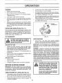
OPERATOR'S
Standard
POSITION
(See Fig. 1)
When right or left hand is mentioned in this manual, it
means when you are in the operating position (standing
behind tiller handles)°
(1) Utility knife
(1) Wire cutter
FRONT
(1) Screwdriver
(1) Tire pressure gauge
(t) Pair of pliers
(1) 9/16" wrench
LEFT
RIGHT
OPERATOR'S
POSITION
FIG. 1
CONTENTS
OF HARDWARE
...........................
PACK
,, ,,,,,,,,,,,,,
G
(2) Handle Locks
,,,,
(1) Carriage Bolt 3/8-16 UNC x I Gr 5
i IIIIIIIH
ii,,111
(1) Flat Washer 13t32 x I x 11 Ga,
i
(2) Hairpin Clips
i,
(1) Center Locknut 3/8-16 UNC
i iiiiiiiir
.........
(1) Handle Lock Lever
(1) Cable Clip
ii
i iii
(1) Pivot Bolt
3/8-16 UNC Grade 5
L_ ,i,
6
i iiiii
Extra Shear Pins & Ciips
,,11,,,,,i,...............
i,
,
,
,........
1,1,1
L'L_
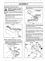
ASSEMBLY
.....................
i,
UNPACKING
,
i
,,,i,i1,,,,,i,i,
CARTON
,i,i1,,,,,i,,,i,ii, ii,
(See Fig, 2)
o
,i , ,
Grasp handle assembly, HoIdin"up"position. Be sure
handle lock remains in gearcase notch, Slide handle
assembly into position,,
",j._., _:,:
,_,::
IMPORTANT;
WHEN UNPACKING AND ASSEMBLING
TILLER, BE CAREFUL NOT TO STRETCH OR KINK
CABLES,,
,
.:_,_
"UP" POSITION
+,j.f,_f
HANDLE
While holding handle assembly, cutcabletiessecuring
handle assembly to top frame and depth stake_ Let
handle assembly rest on tiller,
o
Remove top frame of carton°
•
Slowly ease handle assembly up and place on top of
carton,
o
Cut down right hand front and right hand rear' corners
of carton, lay side carton wall down.
•
Remove packing material from handle assembly°
•
Separate shift rod from handle assembly,
LOCK
HOLD
__
ASSEMBLY
LEVERTO
TIGHTENHANDLE
LOOSEN HANDLE _
LOCK LEVER TO
MOVE
FIG. 4
.
SHIFT ROD
HANDLE
ASSEMBLY
INSTALL HANDLE (See Figs. 3, 4, and 5)
Insert one handle lock (with teeth facing outward) in
gearcase notch_ (Apply grease on smooth side of
handl_ lock to aid in keeping lock in place until handle
assembly is lowered into position.)
=
Insert pivot bolt in front part of plate and tighten.
Cut down remaining corners of carton and lay panels
flat.
=
Lower the handle assembly,, Tighten nut on carriage
bolt so handle moves with some resistance. This wil!
allow for easier adjustmenL
•
Place flat washer on threaded end of handle lock lever.
°
Insert handle 10ck lever" through handle base and
gearcase. Screw in handle lock lever just enough to
hold lever in place.
=
Insert second handle 10Ck(with teeth inward) in the slot
of the handle base (just inside of washer).
•
Raise handle assembly to highest position and securely tighten handle lock lever by rotating clockwise.
Leaving handle assembly in highest position will make
it easier to connect shift rod.
GEARCASE
HANDLE
HANDLE
LOCK
REAR
CARRIAGE
VIEW FROM R,H. SIDE OF TILLER
\
Rotate handle assembly down. Insert rear carriage bolt
first, with head of bolt on LH. side of tiller and loosely
assemble Iocknut (See Fig. 5).
o
FIG. 2
o
I
BOLT
ASSEMBLY
FLAT
WASHER
SLOT
_
'
LOCK
LEVER
GEARCASE
NOTCH
HANDLE
HANDLE
LOCK
HANDLE
BASE
"_
LOCKNUT
FIG. 3
7
FIG. 5
PIVOT
BOLT
CONNECT
SHIFT
REMOVE
ROD (See Fig. 6)
TILLER
FROM CRATE
o
Insert end of shift rod farthest from bend into hole of
shift lever indicator.
,
Adjust handte assembyto lowest position, Be sure lock
lever is tightened securely°
•
Insert hairpin clip through hole of shift rod to securer
o
°
Insert other end of shift rod into hole in shift lever.
Make sure shift lever indicator is in "N" (neutral) position (See Fig. 6)
°
Insert second hairpin clip through hole of shift rod°
°
Tilt tiller forward by lifting handle° Separate cardboard
cover from leveling shield.
ATTACHTHISEND
TOSHIFTLEVER
o
ATTACHTHIS
ENDTO SHIFT
Rotate tiller handle to the right and pull tiller out of
carton.
INSERT
INDICATOR
_
LEVER
°
SHIFT ROD
......................
SHIFT
i,i
CLIP
(See Fig. 7)
Insert plastic cable clip into hole on the back of handle
column_ Push cables into clip.
HANDLE
COLUMN
-\
i,,
HAIRPIN
CLIP
CABLE
SHIFT
LEVER
INDICATOR
CABLES
FIG. 7
CHECK TIRE PRESSURE
i
ii
The tires on your unit were overinflated at the factory for
shipping purposes,
Correct and equal tire pressure is
important for best tilling performance°
i
SHIFT
o
Reduce tire pressure to 20 PSI°
HANDLE
•
HAIRPIN CLIP
SHIFT ROD
FIG. 6
8
HEIGHT
Handle height may be adjusted to better suit operator.
(See 'TO ADJUST HANDLE HEIGHT" in the Service
and Adjustments section of this manual)_
L_
,.i .....
I
'
,....
I" "'111"'11'11'""='"1'""11'1"1
........
I1'1 I1'11"11"1'1111
, , ,I,,,,,,,I,,
"1"'11'1' '
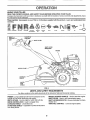
OPEF ATmON
.,,
..............
KNOW YOUR
,,..
i
,,, i i, i ii iii, ,i, ,i,,i,,,i,M'IIII
"11'"'1''11I
TILLER
READ THIS OWNER'S MANUAL AND SAFETY RULES BEFORE OPERATING YOUR TILLER,
Compare the illustrations with your tiller to familiarize yourself with the location of various controls and adjustments, Save
this manual for future reference°
These symbols
meaning.
may appear on your Tiller or in literature
supplied
with the product.
Learn and understand their
STOP O
T{LL|NG
FORWARD
NEUTRAL
REVERSE
DRIVE _
CONTROL _
BAR
CAUTION
OR WARNING
ENG1NE
ON
ENGINE
OFF
FAST
SLOW
CHOKE
FUEL
OtL
THROTTLE
CONTROL
SHIFT LEVER
INDICATOR
PRIMER
DEPTH STAKE
LEVELING
SHIELD
_
_
_
_
_
_\_
RECOIL
STARTER
HANDLE
OUTER
SIDE
SHIELD
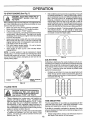
FIG. 8
MEETS ANSI SAFETY
REQUIREMENTS
Our tillers conform to the safety standards of the American National Standards Institute,
PRIMER - pumps additional fuel from the carburetor to the
cylinder for use when starting a cold engine,
DEPTH STAKE - Controls depth at which tiller will dig
DRIVE CONTROL BAR _ Used to engage tines,
LEVELING SHIELD * Levels tilled soil.
OUTER SIDE SHIELD - Adjustable to protect small plants
from being buried.
RECOIL STARTER HANDLE - Used to start the engine,
SHIFT LEVER - Used to shift transmission gears,
SHIFT LEVER INDICATOR - Shows which gear the transmission is in_
THROTTLE
CONTROL - Controls engine speed..
The operation of any tiller can result in foreign objects thrown into the eyes, which can
result in severe eye damage. Always wear safety glasses or eye shields before starting
your tiller and while tilling. We recommend a wide vision safety mask over the spectacles
or standard safety glasses.
i
i,
i,ili,i,
i
i
ill
,_l,r
HOW TO USE YOUR TILLER
DEPTH
Know how to operate all controls before adding fuel and
oil or attempting to start engine_
The depth stake can be raised or lowered to allow you more
versatile tilling and cultivating, or to more easily transport
'our tiller°
STOPPING
STAKE
......................................
(See Fig. 10)
(See Fig. 9)
TINES AND DRIVE
-
Release drive control bar to stop movement.
o
Move shift lever to "N" (neutral) position.
POSITION
SHALLOWES=I
TILLING
ENGINE
o
Move throttle control to "STOP" position.
o
Never use choke to stop engine_
DRIVE CONTROL BAR
"ENGAGED" POSITION
TILLING
.THROTTLE
SHIFT
LEVER
TILLING
DRIVE CONTROL BAR
"DISENGAGED"
POSITION
FIG. 9
TINE OPERATION
•
•
o
Release depth stake pin. Pull the depth stake up for
increased tilling depth. Place depth stake pin in hole of
depth stake to lock in position
.
Place shift lever indicator in 'q" position,
o
Hold the drive control bar against the handle to start
tilling movemenL Tines and wheels will both turn,
-
Move throttle control to "FAST" position for deep tilling.
To cultivate, throttle control can be set at any desired
speed, depending on how fast or slow you wish to
cultivate.
IMPORTANT: ALWAYS RELEASE DRIVE CONTROL BAR
BEFORE MOVING SHIFT LEVER INTO ANOTHER
POSITION
DRIVE
Always release drive control bar before moving shift
lever into another position.
..... movement ts achieved by mowng shift leve r to "T"
Tine
(till) position and engaging drive control bar.
FORWARD•
- WITH WHEEL
(See Fig, 11)
WHEELS
ON LY/TINES
DEPTH STAKE PIN
"RELEASED"
POSITION
\
STOPPED
Release drive control bar and move shift lever indicator
to "F" (forward)position
Engage drive control bar and
tiller will move forward.,
REVERSE
- WHEELS
ONLY/TINES
STOPPED
=
DO NOT STAND DIRECTLY BEHIND TILLER.,
°
Release the drive control bar.
°
Move throttle control to "SLOW" position.
•
Move shift lever indicator to "R" (reverse) position.
=
Hold drive control bar against the handle to start tifier
movement.
"LOCKED"
POSITION
NUT "A"
OUTER
SIDE SHIELD
NUT "B"
FIG. 11
10
...... =,,
=
= ,,H, ,=....
=,, ,,,=,,,,,H,
OPERAT!ON
i
u u, 1,
, = , =,m
, lu,,,H ....
TURNING
ii
Release the drive control bar,
•
•
°
Move throttle control to "SLOW" position.
•
For approximate capacity see "PRODUCT SPECIFICATIONS" on page 3 of this manual. All oil must meet
A.PJ. Service Classification SF or SG.
=
For cold weather operation you should change oil for
easier starting (See oil viscosity chart in the Customer
Responsibilities section of this manual),,
°
To change engine oil, see the Customer Responsibilities section in this manual,,
o
Place shift lever indicator in "F" (forward) position.
Tines will net turn
Lift handle to raise tines out of ground.
Swing the handle in the opposite direction you wish to
turn, being careful to keep feet and legs away from
tines.
To read proper'level, tighten engine oil cap each time.
Reinstall engine oil cap and tighten.
When you have completed your turn-around, release
the drive control barand lower handle. Place shift lever
in "T" (till) position and move throttle control to desired
speed, To begin tilling, hold drive control bar against
the handle,
OUTER
SIDE SHIELDS
OIL FILL
CAP/DIPSTICK
(See Fig. 11)
The front edges of the outer side shields are slotted so that
the shields can be raised for deep tilling and lowered for
shallow tilling to protect small plants from being buried.
Loosen nut "A" in slot and nut "B"_ Move shield to desired
position (both sides)° Retighten nuts.
FIG. 12
TO TRANSPORT
,,, =,, =, =,,=,,=1=
....
ADD GASOLINE
CAUTION: Before lifting or transporting, allow tiller engine and muffler to
cool. Disconnectsparkplugwire.
Drain
gasoline from fuel tank.
..........
i
,
,, i
=
Fill fuel tank
Use fresh, clean, regular unleaded
gasoline. (Use of leaded gasoline wilt increase carbon
and lead oxide deposits and reduce valve life.)
IMPORTANT: WHEN OPERATING IN TEMPERATURES
BELOW 32°F (0°C), USE FRESH, CLEAN, WINTER GRADE
GASOLINE TO HELP INSURE GOOD COLD WEATHER
STARTING.
,i iiil,,,,,,i,,llqi,
AROUND THE YARD
•
Release the depth stake pin,. Move the depth stake
down to the top hole for transporting the tiller, Place
depth stake pin in hole of depth stake to lock in position,
This prevents tines from scuffing the ground.
o
Place shift lever indicator in "F" (forward) position for
transporting°
•
Hold the drive cont{ol bar against the handle to start
tiller movement, Tines will net turn.
•
Move throttle control to desired speed,
WARNING:
Experience indicates that alcohol blended
fuels (called gasohot or using ethanol or methanol) can
attract moisture which leads to separation and formation of
acids during storage° Acidic gas can damage the fue!
system of an engine while in storage. To avoid engine
problems, the fuel system should be emptied before
storage of 30 days or longer, Drain the gas tan k, start the
engine and let it run untit the fuel lines and carburetor are
empty_ Use fresh fuel next season. See Storage section
of this manual for additional information, Never use engine
or carburetor cleaner products in the fuel tank or permanent
damage may occur_
AROUND'TOWN
°
°
Disconnect spark plug wire,
Drain fuel tank.
-
Transport in upright position to prevent oil leakage.
BEFORE
STARTING
&
ENGINE
IMPORTANT:
BE VERY CAREFUL NOT TO ALLOW DIRT
TO ENTER THE ENGINE WHEN CHECKING OR ADDING
OIL OR FUEL. USE CLEAN OtL AND FUEL AND STORE
IN APPROVED,
CLEAN, COVERED CONTAINERS.
USE
CLEAN FILL FUNNELS.
CHECK
•
=
=
ENGINE
Do not overfill. Wipe off any spilled oil
or fuel, Do not store, spill or use gasoline near an open flame.
OIL LEVEL (See Fig. 12)
The engine in your unit has been shipped, from the
factory, already titled with SAE 30 summer weight oil,
Be sure tiller is tevel and the area around oil fill is clean_
Check oil level before each use,, Add oil if needed° Fill
to full line on dipstick.
CAUTION: Fill to within 1/2 inch of top
of fuel tank to prevent spills and to
allow for fuel expansion, if gasoline is
accidentally spilled, move machine
away from area of spill. Avoid creating
any source of ignition until gasoline
vapors have disappeared.
11
OPERATUON
i
i, ,,,11
TO START ENGINE (See Fig. 7)
When starting engine for the first time or if engine has run
out of fuel, it will take extra pulls of the recoil starter to move
fuel from the tank to the engine.
= Make sure spark plug wire is properly connected.
•
Move shift lever indicator to "N" (neutral) position..
•
Place throttle controlin "FAST" po_ition.
= To start a cold engine, push primer five (5) times before
trying to start. Use a firm push. This step is not usually
necessary when starting an engine which has already
run for a few minutes,
o Grasp recoil starter handle with one hand and grasp
tiller handle with other hand. Pull rope out slowly until
engine reaches start of compression cycle (rope will
pull slightly harder at this point)°
°
Pull recoil starter handle quickly. Do not let starter
handle snap back against starter.
= Allow engine to warm up for a few minutes before
engaging tines.
NOTE: In cooler weather it may be necessary to repeat
priming steps., in warmerweather over priming maycause
flooding and engine will not start° If you do flood engine,
wait a few minutes before attempting to start and do not
repeat priming steps.
o
Soil conditions are important for proper tilling° Tines will
not readily penetrate dry, hard soil which may contribute to excessive bounce and difficult handling of your
tiller° Hard soi! should be moistened before tilling;
however, extremely wet soil will "ball-up" or clump
dudng tilling° Wait until the soil is less wet in order to
achieve the best results. When tilling in the fall, remove
vines and long grass to prevent them from wrapping
around the tine shaft and slowing your tilling operation.
°
Do not lean on handle° This takes weight off the wheels
and reduces traction. To get through a reaIly tough
section of sod or hard ground, apply upward pressure
on handle or lower the depth stake.
77
_1f
i/
/J
//
//
/i'
FIG. 14
CULTIVATING
Cultivating is destroying the weeds between rows to prevent them from robbing nourishment and moisture from the
ptants. At the same time, breaking up the upper layer of soil
crust will he}p retain moisture in the soil. Best digging depth
is 1" to 3". Lower the outer side shields to protect small
plants from being buried.
=
Cultivate up and down the rows at a speed which wi!)
allow tines to uproot weeds and leave the ground in
rough condition, promoting no further growth of weeds
and grass (See Fig. 15).
RECOIl. STARTER
HANDLE
PRIMER
FIG. 13
TILLING
HINTS
.................
©
,,=,,11
.........
\_1
O
handling your tiller, start actual field
use
with throttle
in slow
position (m!dCAUTION:
Until you
are accustomed
to
way between "FAST" and "IDLE").
, ,
°
o
,i,
i,,11....
i
i,=
Tilling is digging into turning over, and breaking up
packed soil before" planting° Loose, unpacked soi!
helps root growth° Best tilling depth is 4 to 6'. A tiller
will also clear the soil of unwanted vegetation, The
decomposition of this vegetable matter enriches the
soil. Depending on the climate (rainfall and wind), it
may be advisable to till the soil at the end of the growing
season to further condition the soil.
For easier handling of your tiller, leave about 8 inches
of untilled soil between the first and second tilling
passes. The third pass will be between the first and
second (See Fig. 14).
FIG. 15
TINE SHEAR
PINS
The tine assemblies on your tiller are secured to the tine
shaft with shear pins (See 'q-INE REPLACEMENT" in the
Service and Adjustments section of this manual)°
If the tiller is unusually overloaded or jammed, the shear
pins are designed to break before internal damage occurs
to the transmission°
,
12
If shear pin(s) break, replace only with those shown in
the Repair Parts section of this manual
................
i,
CUSTOMER
, , =,,H=................................................
RESIPON
,=
'
, ....
, ........
ii,, ,,,=....
BILUTIES
,
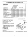
SCHEDULE
REGULAR SERVICE
=
,
Check Engine 0it Level
=lull
Ill,
_#'
,= ,,=
H,= ........
H,u
H= HH
''
=
I
=!,
Change Engine Oil
= ,H , 111
,
_#'
1_1,2
..................
Oil Pivot Points
Inspect Spark Attester / Muffler
=
i
Inspect AIr Screen
_'
=ui!==,=
Clean or Replace Air Cfeaner Cartridge
_2
1,, ,,1, ,111 ==u
Clean Engine Cylinder Fins
Replace Spark Plug
_#_
1 - Chango mote often when operating under a heavy load or in high ambient temperatures,
2 - Service more often when operating in ditty or dusty conditions
GENERAL
LUBRiCATiON
RECOMMENDATIONS
CHART
The warranty on this tiiler does not cover items that have
been subjected to operator' abuse or' negligence°
To
receive fufl value from the warranty, the operator must
maintain tiller as instructed in this manual,
* THROTTLE
CONTROL
Some adjustments wilt need to be made periodically to
properly maintain your tiller°
All adjustments in the Service and Adjustments section of
this manual should be checked at least once each
seasom
o
** ENGINE
Once a year you should replace the spark pfug, clean
or replace air filter, and check tines and belts for' wear.
A new' spark plug and clean air filter assure proper airfuel mixture and help your engine run better and last
longer,
BEFORE
PIN
* LEVELING
HINGES
EACH USE
=
Check engine oil level°
•
,
Check tine operation°
Check for' loose fasteners.
* IDLER
BRACKET
WHEEL
HUB
LUBRICATION
Keep unit well lubricated (See "LUBRICATION
* SAE 30 OR 10W-30 MOTOR OIL
** REFER TO CUSTOMER RESPONSIBILITIES "ENGINE" SECTION
CHART").
13
m
,_ .....................
n,,,,, i,, ,,i
CUSTOMER
RESPONSBB L TmES
,, ii,lll,r,t
Disconnect spark plug wire before performing any maintenance (except carburetor adjustment) to prevent
accidental starting of engine.
Preventfires{ Keep the engine free of grass, leaves, spiliedoil, orfuel. Remove fuel from tank before tipping
unit for maintenance. Clean muffler area of all grass, dirt, and debris°
Do not touch hot muffler or cylinder fins as contact may cause burns.
ENGINE
AIR FILTER
LUBRICATION
Use only high quality detergent oil rated with API service
classification SF, SG or SH Select the oil's SAE viscosity
grade according to your expected temperature,
SAE VISCOSITY GRACES
_F
"20_
°c ._o
o
0_
.{o
o
TEMPERATURE
30°
._oo
RANGE
32_
40°
oo
ANTICIPATED
60 _
B0 _
,'o, _oo
BEFORE
(See Fig. 18)
Your engine will not run properly using a dirty air filter,,
Clean the foam pre-cleaner after every 25 hours of opera*
tion or every season° Service paper cartridge every 100
hours of operation or every season, whichever occurs firsL
Service air cleaner more often under dusty conditions,,
°
Remove cover screw and cover,
TO SERVICE PRE-CLEANER
•
Remove foam pre-cleaner from air cleaner cover.,
°
Wash it in liquid detergent and water.
o Squeeze it dry in a clean cloth,
•
Saturate it in engine oil Wrap it in clean, absorbent
cloth and squeeze to remove excess oil
o
If very dirty or damaged, rep{ace pre-cieaner.
•
Reinstall pre-cleaner into air cleaner cover.
.
ReinstalI cover and secure screw.
TO SERVICE CARTRIDGE
= Carefully remove cartridge to prevent debris from entering carburetor.
Clean base carefully to prevent
debris from entering carburetor._
°
Clean cartridge by tapping gently on flat surface° If very
dirty or damaged, replace cartridge.
.
Reinstall cartridge, cover with pre-cleaner and secure
with screw,
IMPORTANT:
PETROLEUM SOLVENTS, SUCH AS
KEROSENE, ARE NOT TO BE USED TO CLEAN THE
CARTRIDGE, THEY MAY CAUSE DETERIORATION OF
THE CARTRIDGE. DO NOT OIL CARTRIDGE
DO NOT
USE PRESSURIZED AIR TO CLEAN OR DRY CARTRIDGE°
100_
30° 40°
NEXT OIL CHANGE
FIG. 16
NOTE: Although multi-viscosity oils (5W-30, 10W*30, etco)
improve starting in cold weather, these multi-viscosity oils
will result in increased oil consumption when used above
32°F (0°C). Check your engine oil level more frequently to
avoid possible engine damage from running low on oil
Change the oil after every 25 hours of operation or at least
once a year ifthe tractor is not used for25 hours in one year,
Check the crankcase oil level before starting the engine
and after each five (5) hours of continuous use. Add SAE
30 motor oil or equivalent. Tighten oil filler plug securely
each time you check the oil level.
TO CHANGE ENGINE OIL (See Figs. 16 and 17)
Determine temperature range expected before oil change,
All oil must meet API service classification SF, SG or SHo
•
Be sure tiller is on level surface.
Oi! will drain more freely when warm°
.
Use a funnel to prevent oil spill on tiller, and catch oil in
a suitable container_
.
Remove oil drain plug and oil fill cap/dipstick,
Be
careful not to allow dirt to enter the engine,
For easier removal of plug use 7/16 12 Pt. socket with
extension.
.
Tip tiller forward to drain oil,
•
After oil has drained completely, replace oil drain plug
and tighten securely°
•
Refill engine with oil through oil fill tube. See "CHECK
ENGINE OIL LEVEL" in the Operation section of this
manual.
FOAM
PRECLEANER
COVER
COVER
SCREW
AIRCLEANER
CARTRIDGE
FIG. 18
COOLING
SYSTEM
(See Fig. 19)
Your engine is air cooled° For proper engine performance
and long life keep your engine clean°
•
Clean air screen frequently using a stiff-bristled brush°
°
Keep cylinder fins, levers, and linkage free of dirt and
chaff..
MUFFLER
o,,.
i
.<j---_,
_
CYLINDER
FINS
PLUG_
AIR SCREEN
FIG, 17
14
FIG. 19
,
IH ,I,H,I,
CUSTO
ESPONSBBmLmTIES
,
,,,,
, ii,i
i ,i ,ml,m
i1,1
,,,
m,ii
MUFFLER
TRANSMISSION
Do not operate tiller without muffler.. Do not tamper with
exhaust system. Damaged mufflers or' spark arresters
could create a fire hazard° Inspect periodically and replace
if necessary, if your engine is equipped with a spark
arrester screen assembly, remove every 50 hours for
cleaning and inspection Replace if damaged
Your transmission is sealed and will only require lubrication
if serviced,
SPARK
CLEANING
PLUG
Replace spark plugs at the beginning of each tilling season
or after every 50 hours of use, whichever comes first. Spark
plug type and gap setting is shown in "PRODUCT SPECIFICATIONS" on page 3 of this manual.
°
Clean engine, wheels, finish, etc. of alt foreign matter.
o
Keep finished su daces and wheels free of all gasoline,
oil, etc..
o
Protect painted surfaces with automotive type wax..
We do not recommend using a garden hose to clean your
unit unless the muffler, air filter and carburetor are covered
to keep waterouL Water in engine can result in a shortened
engine life
ADJUSTMENTS
$E
CAUTION: Disconnect
contact with plug,
,
spark plug wire from spark plug and place wire where it cannot come into
,r_r ,,r,
i
TILLER
l'O REMOVE
WHEEL
(See Fig. 21)
o
Place blocks under transmission
tipping.
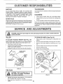
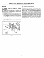
Select handle height best suited for your tilling conditions,
Handle height will be different when tiller digs into soil,
= First loosen handle lock lever,
o
Remove outer side shield by _emoving nuts"A" and"B"
-
Remove inner side shield by removing nuts "C" and
"D"_
=
Handle can be positioned at different settings between
"HIGH" and "LOW" positions,
o
Remove hairpin clip and clevis pin from wheel
Remove wheel and tire_
.
Retighten handle lock lever securely after adjusting,
-
Repair tire and reassemble°
TO ADJUST
HANDLE
HEIGHT
HANDLE
(See Fig.
20)
to keep tiller from
(HIGH
)
HANDLE
LOCK
LEVER
HANDLE (LOW
POSITION)
I
HAIRPIN
CLIP
FIG. 20
INNER SIDE
i
TIRE CARE
OUTER SHIELD
SIDE
SHIELD
NUT "B"
_
less beads are seated, overinflation
CAUTION:
When
mounting tires, uncan
cause an
explosion,
,,
, i,
,
ii
,
FIG. 21
,
•
Maintain 20 pounds of tire pressure. If tire pressures
are not equal, tiller will pull to one side,
•
Keep tires free of gasoline or oil which can damage
rubber°
15
, iiiiil,,,u,,ul
, ,,11,,i
SERVmCE AN
ADJUSTMENTS
i1,,
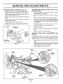
TO REMOVE
•
BELT
GUARD
TO REPLACE
GROUND
Figs. 22 and 23)
(See Fig. 22)
Remove L.H, inner and outer side shields (See "TO
REMOVE WHEEL" in this section of this manual),
DRIVE
BELT
(See
o
Remove belt guard (See''TO REMOVE BELT GUARD"
in this section of this manual)
•
Loosen belt guides "A" and "B" and atso nuts "C" and
°
Remove old belt by slipping from engine pulfey first,
=
•
Remove hex nut and washer from bottom of belt guard
(located behind wheel)
Pull belt guard cut and away from unit
Place new belt in groove of transmission pulley and
into engine pulley BELT MUST BE IN GROOVE ON
TOP OF IDLER PULLEY NOTE POSITION OF BELT
TO GUIDES,
.
Replace belt guard by reversing above procedure
o
Tighten belt guides "A" and "B" and nuts "C" and "D",
=
Check belt adjustment as described below
,
Replace belt guard.
,
Reposition wheel and replace clevis pin and hairpin
ciip_
-
Replace inner and cuter side shields.
o
o
o
Remeve hairpin clip andclevis pinfromleffwheeL
wheef out from tiller about t inch
Pull
Remove two (2) cap nuts and washers from side of belt
guard,
BELT GUARD
CAP NUT
AND WASHER
=o,
.o, x
GROUND
Fig. 23)
WASHER
""
/
CAP NUT
AND WASHER
_z__l__\
BEHIND
TIRE)
BELT
ADJUSTMENT
HAIRPIN CLIP AND
CLEVIS PiN
•
Loosen cable clip screw securing the drive control
cable.
,
Slide cable forward for less tension and rearward for
more tension until about 5/8 inch stretch is obtained
while the drive control bar is engaged..
FIGo 22
Tighten cable clip screw securely..
BELT
GUIDE "A'
ENGINE
PULLEY
IDLER
PULLEY
(See
For proper belt tension, the extension spring should have
about 5/8 inch stretch when drive control bar is in "ENGAGED" position This tension can be attained as follows:
_
\
DRIVE
CABLE CLiP
SCREW
BELT
CONTROL
CABLE
EXTENSION
SPRING
TRANSMISSION
PU LLEY
FIG. 23_
16
=,n, =
,
,=,,,,,,===,_
SERVICE
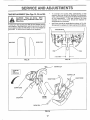
TINE REPLACEMENT
,,i ,11
AND ADJUSTMENTS
-
(See Figs. 24, 25 and 26)
ii i1,1.i,.
,,
gloves or other protection when handling tines.
o
A badly worn tine causes'your ii'i'ler to work harder and dig
mote shallow., Most important, worn tines cannot chop and
shred organic matter as effectively nor bury it as deeply as
good tines A tine this worn needs to be replaced.
To maintain the superb tilling performance of this
machine the tines should be checked for' sharpness,
wear, and bending, particularly the tines which are next
to the transmission.
If the gap between the tines
exceeds 3-I/2 inches they should be replaced or
straightened as necessary
New tines should be assembled as shown in Fig. 26.
Sharpened tine edges will rotate rearward from above..
WORN TINE
NEW TINE
TINE
_TINE
1
I
1
[
3-1t2" MAX--4
FIG. 25
FIG. 24
HAIRPIN CLIP
COUNTER
TINE
ROTATION
HAIRPIN CLIP
SHARP EDGE
SHARP EDGE
SHEAR PiN
EDGES
SHEAR PIN
FIG. 26
17
ENGINE
TO ADJUST
TO ADJUST
THROTTLE
(See Fig. 27)
CONTROL
The carburetor
has been preset at the factory and adjustment should not be necessary,
However, engine performance can be affected by differences
in fuel, temperature,
altitude or load, If the carburetor
does need adjustment,
contact your nearest authorized service cente r/department
CABLE
The throttle control has been preset at the factory and
adjustment should not be necessary° If adjustment is
necessary, proceed as follows:
o
With engine not running, move remote throttle control
[ever to "FAST" position.
°
If throttle lever on engine touches high speed stop, no
further adjustment is necessary, tf throttle lever does
not touch high speed stop, continue with adjustment
procedure_
•
Loosen cable clamp screw°
o
Move throttle lever up until ittouches high speed stop,
and hold in this position_
o
Tighten cable clamp screw securely..
IMPORTANT:
NEVER TAMPER
WITH THE ENGINE
GOVERNOR,
WHICH IS FACTORY
SET FOR PROPER
ENGINE SPEED, OVERSPEEDING
THE ENGINE ABOVE
THE
FACTORY
HIGH
SPEED
SETTING
CAN BE
DANGEROUS_
IF YOU THINK THE ENGINE-GOVERNED
HIGH SPEED NEEDS ADJUSTING,
CONTACT
YOUR
NEAREST
AUTHORIZED
SERVICE
CENTER/
DEPARTMENT,
WHICH HAS THE PROPER EQUIPMENT
AND EXPERIENCE
TO MAKE
ANY
NECESSARY
ADJUSTMENTS
HIGH SPEED STOP \
%
CABLE
THROTTLE
/
CABLE
CLAMP
SCREW
CARBURETOR
THROTTLE
LEVER
FIG. 27
18
ENGINE
Immediately prepare your tiller' for storage at the end of the
season or if the unit will not be used for 30 days or more.
= ,,,,i ....
OIL
Drain eli (with engine warm) and replace with clean oil.
(See "ENGINE" in the Customer Responsibilities section of
this manual)_
i,
CAUTION:
Never store the tiller with
gasoline in the tank inside a building
where fumes may reach an open flame
or spark. Allow the engine to cool
before storing in any enclosure,
CYLINDERS
o
Remove spark plug
o
Pour1 ounce (29 ml) of oil through spark plug hole into
cylinder°
TILLER
o
Pull starter' handie slowly several times to distribute oil
o
Clean entire tiller'(See "CLEANING" in the Customer
Responsibilities section of this manual).
o
Replace with new spark plug.
-
Inspect and replace belts, if necessary (See belt replacement instructions in the Service and Adjustments
section of this manual),
OTHER
•
Do not store gasoline from one season to another.
o
Lubricate as shown in the Customer Responsibilities
section of this manual,,
.
Replace your' gasoline can if your can starts to rust_
Rust and/or dirt in your' gasoline will cause problems.
•
Be sure that all nuts, bolts and screws are securely
fastened° Inspect moving parts fordamage, breakage
and wear'. Replace if necessary.
-
If possible, store your unit indoors and cover it to give
protection from dust and dirt.
•
Touch up al] rusted or chipped paint surfaces; sand
lightly before painting,.
..... i,,,,,i
........................
,,
Cover your unit with a suitable protective cover' that
does not retain moisture. Do not use plastic. Plastic
cannot breathe which allows condensation to form and
will cause your unit to rust.
IMPORTANT:
NEVER COVER TILLER WHILE ENGINE
AND EXHAUST AREAS ARE STILL WARM,
ENGmNE
FUEL SYSTEM
IMPORTANT:
IT IS IMPORTANT TO PREVENT GUM
DEPOSITS FROM FORMING IN ESSENTIAL FUEL
SYSTEM PARTS SUCH AS THE CARBURETOR, FUEL
FILTER, FUEL HOSE, OR TANK DURING STORAGE_
ALSO, EXPERIENCE
INDICATES THAT ALCOHOL
BLENDED FUELS (CALLED GASOHOL OR USING
ETHANOL OR METHANOL) CAN ATTRACT MOISTURE
WHICH LEADS TO SEPARATION AND FORMATION OF
ACIDS DURING STORAGEI ACIDIC GAS CAN DAMAGE
THE FUEL SYSTEM OF AN ENGINE WHILE IN STORAGE.
=
Drain the fuel tank.
o
Start the engine and let it run until the fuel lines and
carburetor are empty.,
.
Never use engine or carburetor cleaner products in the
fuel tahk or permanent damage may occur.
Use fresh fuel next season.
=
NOTE:
Fuel stabilizer is an acceptable alternative in
minimizing the formation of fuel gum deposits during storage_ Add stabilizer to gasoline in fuel tank or storage
container. Always follow the mix ratio found on stabilizer
container. Run engine at least 10 minutes after adding
stabilizer to allowthestabilizerto
reach the carburetor. Do
not drain the gas tank and carburetor' if using fuel stabilizer.
19
I'H'""H"
I" I" I
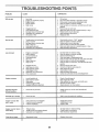
TROUBLESHOOTING
,,
iii i,
i,i P,,,ll
PROBLEM
CAUSE
Wli! not start
i,i ii
i
CORRECTION
1
Out of fuel
2
3
4
5
Engine not "CHOKED"
Engine flooded
Dirty air cleaner
Water in fuel
propedy
I,
Fill fueftank
2
3
4
5
See '3"0 START ENGINE" in Operation section
Wait several minutes before attempting to start
Clean or replace air cleaner cartridge
Drain fuel tank and carburetor, and refitl tank with fresl_
gasoline
Remove fuel tank and clean
6
6
7
8
9
10
Clogged fuel tank
Loose spark plug wire
Bad spark plug ar improper gap
Carburetor out of adjustment,
Oil soaked air filter
7
8
9
10
Make sure spark plug wire is seated properly on plug
Replace spark plug or adjust gap
Make necessary adjustments
Replace air filter
t
2
3
4
5
6
Throttle contro} not sat properly
Dirty air cleaner
Bad spark plug or improper gap
State or dirty fuel
Loose spark plug wire
Carburetor out of adjustment
t
2
3
4
5
6
Place throttle control in 'FAST" position
Ciean or replace air cleaner cartridge
Repiace spark plug or adjust gap
Drain fuel tank and refill with fresh gasoline,
Make sure spark plug wire is seated properly on plug
Make necessary adjustments
1
2
3
4
5
6
7
Set depth stake for shallower tilling
Clean or replace air cleaner cartridge
Check oil level/change oil
Clean and regap or change spark pSug
Drain and clean fuel tank and refill, and clean carburetor
Drain fuel tank and refill with fresh gasoline,
Drain fuel tank and carburetor, and refill tank with fresh
gasoline
Remove rue{ tank and clean
, ,,===,1
Hard to start
i,
POINTS
, , ,, , LILI,]I','U"I'Nr,L',1,', ....................
H,,
ii H,"H',N
Loss of power
1
2
3
4
5
Engine is overloaded
Dirty air cleaner
Low oil tevelfdtrty oil
Faulty spark plug
Oil in fuel
6
7
Stale or dirty fue}
Water in fuel
8
9
10
11
t2
13
8
Clogged fuel tank
Spark plug wire loose
Dirty engine air screen
Dirty/clogged muffler,
Carburetor out of adiustment,
Poor compression
9
10
1!
12
!3
Connect and tighten spark plug wire
Clean engine air screen
Clean/replace muIfler
Make necessary adjustments
Contact an authorized service center/department
, 'H,H"" I","
Engine overheats
1
2
3
4
5
i,
Excessive bounce/
difficult handling
i
1
i
Low oil level/dirty oil
Dirty engine air screen
Dirty engine
Partially plugged muffler
Improper carburetor adjustment
1
2,
3,
4
Check oil level/change oil
Clean engine air screen,
Ctean cylinder fins, air screen, and muffter area
Remove and clean muffler
5
Adjust carburetor to richer position
, i ll,l,,i,,
Ground too dry and hard
Moisten ground or wait for more favorable
conditions,
ii
i, :::::::::::::::::::::::::::::::::::
Wait for more favorable soil conditions,
Soil balls up or clumps
1
Ground too wet.
Engine rune but tiller
won't move
1
2
3
Drive control bar is not engaged
V-bait not correctly adjusted
V-belt Isoff pulley(s)
t
2
3
Engage drive control
Inspect/adjust V-belt
inspect Vobelt
Tilling too deep
1
2
3
Set depth stake for shallower
Check throttle control setting
Make necessary adjustments
1
Repiace shear pin(s)
Engine runs but labors
when tilling
• 1
2
3
Throttle control not properly adjusted
Carburetor out of adjustment
i ,, ,,IHI
Tines will not rotate
1
'"HI'H ........
I
' I .................
Shear pin(s) broken
2O
i
tilling,
soil
i
ii
i
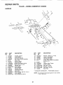
REPARRPARTS
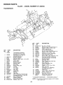
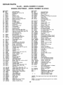
TALLER - - MODEL
NUMBER
917.293650
HANDLES
9
_
_--.:,_
-,'_7-.- _-
•t;%
,
29
15
\
23
tl
\
k..
31 \
KEY
NO,
PART
NO.
1
2
3
4
5
6
7
8
9
10
11
12
!3
14
15
!6
17
18
127012X
141406
110673X
1272"54X
6712J
137119
110641 X
71191008
72010520
110646X
STD624003
81328
110741X
109313X
110702 X
STD533710
109229X
STD541437
DESCRIPTION
KEY
NO.
Throttle, Control
Grip, Handle
Grommet, Handle
Bar, Drive Control Assembly
Cap, Vinyl
Panel, Control
Bushing, Split
* Screw, Pan Head #10-24
* Bolt, 5/16-18 x 2-1/2
Handle, Grip
* Clip, Hairpin
Bolt, Shoulder
Handle, Shift
Grommet, Rubber
Rod, Shift
* Bolt, Carriage 3/8-16 x ! Gr. 5
Lock, Handle
* Nut, Centerlock 3/8-16
PART
NO,
19
20
21
22
23
19131611
109228X
150258
121145X
86777
24
25
26
27
28
29
31
9484R
73970500
110675X
STD541025
STD551125
STD541462
150696
\
DESCRIPTION
Washer 13/32 x 1 x tl Gao
Lever, Lock, Handle
Handle, Assemble
Clip, Plastic, Cable
Screw, Hex, Washer Hd, Slotted
#10-24 x 1/2
Clip
Locknut, Hex, Flange
Clutch, Cable
* Nut, Hex 1/4-20
* Washer', Lock 1/4
*Nut, Keps #10-24
Bolt, Pivot
* STANDARD HARDWARE
NOTE:
21
- - PURCHASE LOCALLY
All component dimensions given in UoS. inches.
1 inch = 25.4 mm
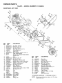
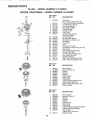
REPAURPARTS
TILLER - - MODEL
MAINFRAME,
NUMBER 917.293650
LEFT SIDE
3
8
1
39
17
21
20
KEY
NO.
PART
NO.
1
2
3
4
5
6
7
8
9
STD54!431
STD551137
STD541037
74930568
154734
110111X
STD532505
8700J
86777
10
11
12
13
14
15
16
17
19
20
21
22
23
9484R
STD551125
STD541025
23230506
120938X
STD551031
145102
STD541031
12000028
!10653X
145216
104214X
5015J
128952
795R
126875X
STD624003
!31159X574
132801
104679X
24
25
26
27
28
DESCRIPTION
26
Nut, Keps 5/t6-18
*Washer, Lock 3/8
* Nut, Hex 3/8-16
Bolt, Hex 5/16-18 x 4-1/4
Screw Shift Lever
Lever, Shift
* Bolt, Carriage 1/4-20 x 1/2 Gr. 5
Plate, Shift indicator
Screw, Hex, Washer Head, Slotted
#10-24 x 1/2
Clip
* Washer, Lock 1/4
* Nut, Hex 1/4-20
* Screw, Set, 5/16-t8 x 3/8
Spacer, Split 0°327 x 0.42 x 2.68
* Washer 11/32 x 11/16 x 16 Ga..
Sheave, Transmission
* Nut, Hex 5/16-18
Ring, Retainer
Guard, Pinch Point
Spacer, Split 0.327 x 0_42 x I 688
Nut, Cap 5/16-18
Tire
Rim
Tire Valve
Rivet, Drilled
* Clip, Hairpin
Guard, Belt
Beft, V
Pulley, Idler
23
22
24
25
KEY
NO.
29
30
31
32
33
34
35
36
37
38
39
41
42
43
PART
NO,
12000032
105611X
102384X
10214IX
STD523710
102383X
74760532
102331X
130812
145822
140062
19111610
15t004
69t 80
DESCRIPTION
Ring, Klip
Bracket, Idler
Bolt, Hex 5/16-16 × 12
Shaft, Idler Arm
* Bolt, Hex 3/8-16 x 1
Counterweight, L.Ho
Bolt, Hex 5/16-18 x 2
Bracket, Reinforcement, L..H.
Sheave, Engine
Stud, Guard Belt
Cap, Plunger
Washer 11/32 x 1 x 10 Ga
Spacer
Nut Lock #10-24
*STANDARD HARDWARE
NOTE:
22
- - PURCHASE
All component dimensions
1 inch = 25.4 mm
LOCALLY
given in U.S. inches°
REPAIR PARTS
TILLER - - MODEL NUMBER
MAINFRAME,
917.293650
RIGHT SIDE
/
15
/
/
t3
\
6
10
KEY
NO.
1
2
3
4
5
6
7
8
9
10
11
PART
NO.
157976
73970500
STD551031
74760512
102332X
74760532
102173X
STD551137
STD541037
74760524
STD624003
KEY
PART
NO,
NO.
t2
126875X
13 5015J
128952
795R
14 STD541431
15 ......
DESCRIPTION
Bumper
Locknut, Hex, Flange 5116-18
* Washer 11/32 x 11/16 x 16 Ga
Bolt, Hex 5/16-18 x 3/4
Bracket, Reinforcement
Bolt, Hex 5/16-18 x 2
Counter Weight, R.H.
* Washer, Lock 3/8
* Nut, Hex 3/8-16
Bolt, Hex 5/16-18 x 1-1/2
* Clip, Hairpin
DESCRIPTION
Rivet, Drilled
Tire
Rim
Tire Valve
* Nut, Keps 5/16-18
Engine, (See Breakdown)
Craftsman Model No. 143.976001
* STANDARD HARDWARE
NOTE:
23
- - PURCHASE LOCALLY
All component dimensions
t inch = 25..4 turn
given in U.SJnches.
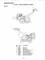
REPAnB PARTS
TgLLER - - MODEL
NUMBER
9'17.293650
TRANSMISSION
11
6
5
1B
44
48
53
18
5O
KEY
PART
NO.
NO.
1 154354
2
150698
3
4
5
6
7
8
9
10
11
12
13
'14
15
!6
18
19
20
106211X
5020J
1370H
137335
145101
4895H
154467
7392M
100371K
106160X
142145
8353J
12000039
154466
4358J
12000040
I02114X
21
22
23
24
102115X
6803J
102111X
STD551143
KEY
NO.
25
27
28
29
30
31
32
33
34
35
36
DESCRIPTION
Transmission Assembly
(Includes Key Nos. 2-52)
Gearcase, L.H.. w/Bearing
(includes Key No. 4)
Gasket, Gearcase
Bearing, Needle
Washer, Thrust 5/8 x 110 x 1/32
Pinion, Input
Shaft, Input
Bearing, Needle
Washer, Seat
Bal!, Steel
Spring, ShAft, Fork
O-Ring
Arm, Shift
Fork, Shift
Ring, Klip
Shaft, Shift
Washer
Ring, Klip
Gear, Assembly, Reverse Idler
(Includes Key Nos. 21 and 22)
Gear, Reverse Idler
Bearing, Needle
Shaft, Reverse Idler
* Washer, Lock 7/16
PART
NO.
STD541143
143009
106390X
102134X
150737
143008
106388X
102121X
102112X
102101X
154355
37
38
39
40
41
42
43
44
48
4422J
154356
105345X
105346X
8358J
4220R
106146X
155236
150700
49
50
51
52
53
--
132688
106147X
17720408
73220500
122204X
6066J
DESCRIPTION
* Nut, Hex 7/16-20
Bearing, Shaft, Ground Drive LrH.
Spacer 0.765 x 1.125 x 1.23
Chain #35-50 Pitch
Ground Shaft Assembly
Bearing, Shaft, Ground Drive R.H.
Spacer 070 x 1.00 x 1.150
Sprocket and Gear Assembly
Shaft, Reduction (2rid)
Screw, Whiz, Lock 5/16-18 x 3-t/2
Sprocket Assembly w/Bearing
(lncfudes Key Nos. 37 and 38)
Bearing, Needle
Sprocket, Tine
Gear, Ciuster, Red 1st & 2rid
Gear, Reverse
Shaft, Reduction (1 st)
Washer, Thrust
Spacer 1.0t x 1_75 x 0_760
Seal, Asm_ Oil
Gearcase, R.Ho w/Bearing
(Includes Key No. 8)
Shaft, Tine
Chain, Roller #50450 Pitch
Screw 1/4-20 x 1/2
* Nut, Hex 5/16-18
Bearing Kit, Tine Shaft
Grease, Plastilube #I
* STANDARD HARDWARE - - PURCHASE LOCALLY
NOTE:
24
All component dimensions given in U.S. inches°
1 inch = 25.4 mm
REPAIR PARTS
TILLER -- MODEL
NUMBER
917.293650
TINE SHIELD
5
5
9
18
28
25 16
27
/%
24
22
24
23
29
18
1
t9
21
J
KEY
NO.
1
2
3
4
5
6
PART
NO.
98000129
104086X574
8393J
12000036
STD533107
8394J
DESCRIPTION
Nut, Flange 5/t6-18
Shield, Side, Outer L.H.
Pin, Stake, Depth
Ring, Ktip
* Bolt, Carriage 5/16-18 x 314 Gr5
Spring
7
8
9
10
11
12
13
14
15
16
8392J
109230X
124289X574
STD533110
STD541031
STD551131
72110510
124311X
104101X574
73510400
Bracket, Latch
Spring, Depth Stake
Shield, Tine
* Bolt, Carriage 5/16-18 x 1 Gr. 5
*Nut, Hex 5/16-18
*Washer, Lock 5/16
Bolt, Carriage 5/16-18 x 1-t/4
Bracket, Shield Tine
Shield, Side, Outer R.H.
Nut, Hex 1/4-20
KEY
NO.
18
t9
20
21
22
PART
NO.
STD532512
102701X
STD541037
102156X
74930632
23
24
25
26
27
4440J
72140404
6712J
109227X
102695X574
28
29
30
120588X
124309X574
73970500
DESCRIPTION
* Bolt, Carriage 1/4-20 x 1-1/4 Gr. 5
Grip
* Nut, Hex 3/8-16
Stake, Depth
Bolt, Hex 3/8-16 x 2
Hinge
* Bolt, Carriage 1/4_20 x 1/4
Cap, Vinyl
Pad, Idler
Shield, Leveling
Pin, Hinge
Shield, Side
Locknut, Hex, F_ange
* STANDARD HARDWARE
NOTE:
25
- - PURCHASE LOCALLY
All component dimensions
1 inch = 25r.4 mrn
given in U_S. inches,
REPABR PARTS
TILLER -- MODEL NUMBER
917.293650
TINE ASSEMBLY
2
I
I
I
3
\
11
"\
\
KEY
NO,
1
2
3
4
5
6
7
PART
NO.
4459J
132673
6554J
STD624008
132727
73610600
STD551137
KEY
NO.
DESCRIPTION
PART
NO,
DESCRIPTION
8 74610616
Bolt, Hex 3/8-24 x 1
9 4460J
Tine, Outer, R.Ho
!0
t32728
Assembly, Hub and Plate, RH
tl
6555J
Tine, Inner, R.Ho
* STANDARD HARDWARE - - PURCHASE LOCALLY
Tine, Outer, Loll..
Pin, Shear
Tine, Inner, L,.H.
* Clip, Hairpin
Assembly, Hub and Plate, Loll.
Nut, Hex 3/8-24
* Washer, Lock 3/8
NOXE: All component dimensions
1 inch = 25.4 mm
26
given in U.S. inches,
REPAIR PARTS
TILLER -- MODEL NUMBER
917.293650
DECALS
i@
6
°\
KEY
NO.
1
2
3
4
5
6
7
8
9
---
PART
NO.
158095
145023
157982
157983
137538
120431X
102180X
157984
120075X
158309
158310
©
DESCRIPTION
Decal, Logo
Decal, Logo
Decal, Logo
Decal, Description
Decal, Caution, Drive Control
Decal, Hand Placement
Decal, Shift Indicator
Decal, Ccu. Tines Rot. Tines
Decal, Warning, Rotating Tines
Manual, Owner's (English)
Manual, Owner's (Spanish)
27
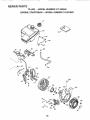
REPARR PARTS
TILLER - - MODEL
ENGINE,
CRAFTSMAN
NUMBER
917.293650
-- MODEL NUMBER
143.976001
307
r
310 --
305
\.,
309
308
130
41
120
86
254
16
416
240
/
245
245A
250
251
238
28
REPAIR PARTS
TILLER -- MODEL
ENGaNE, CRAFTSMAN
NUMBER
917.293650
- - MODEL NUMBER
143.976001
30l
7
400¸
2go
lOO
\
25A
292
26
370A
25
285
261
261A
I
390
287
2O9
jO
327
29
REPAnR PARTS
TBLLER -- MODEL NUMBER
ENGINE, CRAFTSMAN
KEY
NO.
1
2
14
15
16
17
18
19
20
25
25A
26
30
35
36
37
38
40
4O
41
41
PART
NO.
36866
26727
28277
30589
36618
36700
651028
36710
32600
36621
36622
30200
34740
29826
29918
29216
29642
40004
40OO5
36070
36071
42
42
43
45
40006
40007
20381
32875A
46
48
49
50
60
64
65
69
70
72
75
80
81
82
83
86
89
90
92
93
100
101
103
110
119
120
125
125
32610A
35616
36611
36620
36623
650738
30200
36624
36625
27642
27897
30574A
30590A
30591
36057
650488
610961
611205
650815
6508'16
34443A
610118
651007
36054
36719
36721
36471
36472
126
t26
130
130A
135
150
151
153
154
155
157
158
159
160
161
29314B
29315C
650912
65O999
34645
31672
31673
36649
650913
35624A
650914
36629
35626
36630A
651008
9'17.293650
-- MODEL NUMBER
DESCRIPTION
Cylinder (lnci 2, 20 & 72)
owel Pin
Washer
Governor Rod
Governor Lever
Governor Lever Clamp
Screw, TorxT_15, 8-32 x 3/8"
Extension Spring
Oil Seal
Air Baffle (Left)
Air Baffle (Right)
.
Screw, 10-24-x 9/16
Crankshaft
Screw, 10-32 x 3/4"
Lock Washer
Lock Nut, I0-32
Retaininq Rinq
Piston Pin & Ring Set (Std.)
Piston, Pin & Ring Set (.010" OS)
Piston & Pin Ass'y (Std) (Incl. 43)
Piston & Pin Ass'_/
(.010" OS) (IncL 43)
Ring Set (St&l,
Ring Set (_010 OS)
Piston Pin Retaining Ring
Connecting Rod Ass'y
(lnct 46 & 49)
Connecting Rod Bolt
Valve Lifter
Oil Dipper
CamsHaft (lncl. 253 & 254)
Blower Housing Ex!ension
Screw, 1/4-20 x 5/8
Screw, 10-24 x 9/16"
* Cylinder Cover Gasket
Cyl_der Cover (Incl 75 thru 83)
uKt urain l-'lug
Oil Seat
Governor Shaft
Washer
Governor Gear Ass'y (Incl. 81)
Governor Spool
Screw, 1/4-20 x 1-1/4"
Flywheel Key
Flywheel
Belteville Washer
Flywheel Nut
Solid State ignition
Spark Plug Cover
Screw, Torx T-15, 10-24 x 15/16"
Ground Wire
* Cylinder Head Gasket
Cylinder Head
Exhaust Valve (Std.) (Incl. t51)
Exhaust Valve (1/32" OS)
(IncL. 151)
Intake Valve (Std.) (Incl. 151)
Intake Valve (1/32" OS) (Incl. 151)
Screw, 5/16-18 x 1q/2"
Scr_ew,5/16-18 x 2_4t/64"
Resistor Spark Plug (RN4C)
Valve Spring
Valve Spring ,Cap
Push Rod G-uiae
Rocker Arm Stud
Rocker Arm
Nut, I/4-28
Push Rod
* Rocker Arm Cover Gasket
Rocker Arm Cover
Screw, 1/4-20 x 3t/64"
KEY
NO.
173
178
182
184
185
186
200
PART
NO.
36675A
650852
650451
26756
36631
36711
36736
206
207
209
210
211
223
224
238
239
240
245
245A
250
251
252
253
254
260
261
261A
262
275
277
285
287
290
292
298
300
301
305
307
308
309
310
313
325
327
340
341
342
342A
370A
380
390
400
610973
36632
650821
27793
28942
650451
36581
28820
27272A
36633
36046
36634
36635A
650886
650821
36701
36702
36992
651008
650821
651008
36759
650988
35985B
651008
30705
26460
650665
36875
36246
36877
35499
36651
6510tl
36878
34080
29443
35392
36876
36644
651010
650738
36261
640025
590704
36720
416
36085
417
600
900
900
650760
651013
143.976001
DESCRIPTION
Breather Tube
Nut,
1/4-20
Screw,
1/4-20 x 1"
* Carburetor To Intake Pipe Gasket
Intake Pipe
Governor Link
Control Bracket
#ncL 206, 210 & 211)
erminal
Throttle Link
Screw, 10-32 x 1/2"
Conduit Clip
Screw, 10-32 x 3/8"
Screw, 1/4-20 x 1"
* Intake Pipe Gasket
Screw, 10-32 x 1/2
* Air CIeaner Gasket
Air Cleaner Body (Incl 239)
Air Cleaner Filter
Air Cleaner Filter
Air Cleaner Cove_ P°fy)
_]cing Nut
rew, 10-32 x 1/2"
Compression Release Weight
Compression Release Spring
Blower _ousing
Screw, 1/4-20 x 31/64"
Screw, 10-32 x 1/2"
Screw, 1/4÷20 x 31/64"
Muffler
Screw, 1/4-20 x 2-9/32"
Starter Cup
Screw_ 1/4-20 x 31/64"
Fuel Line
Fuel Line Clamp
.
Screw, 1/4-15 x 3/4
Fuel Tank
292 & 30't )
Fuel Cap (Incl.
Oil Fill Tube
"O" Ring
Fill Tube Clip
,,
Screw, 10-32 x 15/16
Dipstick
Spacer
Wire Clip
Starter Pluq
Fuel Tank Bracket (Upper)
Fuel Tank Bracket (Lower)
Screw, 1/4-20 x 7/8"
Screw, 1/4-20 x 5/8"
Lubrication Decal
Carburetor (Incl 184)
Rewind Starter
Gasket Set
_ncl Items Marked * in Notes)
park Arrestor Kit
(lncL 417) (Optional)
Screw, 8-32 x 3/8"
Washer
Replacement Engine - None
Replacement S/I_ 754295,
order from 71-999
RPM High 3050 to 3350
RPM Low 1650 to 1950
(NOTE_ This engine could have been built with 590746
starter,)
NOTE: All component dimensions given in U.S. inches
1 inch = 254 mm
3O
REPAIR PARTS
TILLER
- - MODEL
ENGnNE, CRAFTSMAN
NUMBER
-- MODEL
917.293650
NUMBER
KEY PART
NO. NO.
640025
1
2
4
5
6
7
16
17
631615
631767
631184
631183
631036
650506
632164
650417
18
20
20A
25
27
28
29
30
31
35
36
37
40
44
47
48
630766
640018
640053
631867
631024
632019
631028
631021
631022
36045
640019
632547
640015
27110
630748
631027
KEY PART
NO. NO.
1
2
3
4
5
6
7
8
11
12
13
590704
590599A
590600
590696
590601
590697
590698
590699
590700
590705
590535
590701
KEY PART
NO. NO.
_]--,
31
1
2
3
4
5
6
7
8
11
12
590746
590599A
590600
590679
590601
590678
590680
590412
590681
590747
590535
13
590701
143.976001
DESCRIPTION
Carburetor
(lncI 184 or Engine Parts list)
Throttle Shaft & Lever Assembly
Throttle Return Spring
Dust Seal Washer
Dust Seat (Throttle)
Throttle Shutter
Shutter Screw
Fuel Fitting
Throttle Crack Screw/
Idle Speed Screw
Tension Spring
Idle Restdctor Screw
Idle Restrictor Screw Cap
Float Bowl
Float Shaft
Float
Float Bowl "O" Ring
Inlet Needle, Seat, & Clip (Incl. 31)
Spring Clip
Primer Bulb/Retainer Ring
Main Nozzle Tube
"O" Ring, Main Nozzle Tube
High Speed Bowl Nut
Bowl Nut Washer
Welch Plug, Idle Mixture Well
Welch Plug, Atmospheric Vent
,DESCRIPTION
Recoil Starter
Spring Pin (Incl, 4)
Washer .................................................
Retainer
Washer
Brake Spring
Starter' Dog
Dog Spring
Pulley & Rewind Spring Ass'y.
Starter Housing Ass'y..
Starter' Rope ( 98" X 9/64" dia.)
Starter Handle
DESCRIPTION
Recoil Starter
Spring Pin (lncl. 4)
Washer
Retainer
Washer'
Brake Spring
Starter Dog
Dog Spring
Pulley & Rewind Spring Assembly
Starter Housing Assembly
Starter Rope
(Length 98" x 9/64" dia.)
Starter Handle
®
8.0 HP
17 INCH TINE WIDTH
EAR T!
TILLER WITH
OOLINTEFI ROTATING TINES
MODEL NO=
917.293650
Each tiIler has its own model number.
number.
Each engine has its own model
The model number for your tiller will be found on a plate attached to the
top of the transmission.
The model number for your engine will be found on the blower housing of
the engine.
All parts listed herein may be ordered from any Sears, Roebuck and Co.
Service Center!Department and most Retail Stores,
iF YOU NEED
REPAIR SERVmCE
OR PARTS:
WHEN ORDERING REPAIR PARTS, ALWAYS
ING INFORMATION:
FOR REPAIR SERVICE, CALL
THIS TOLL FREE NUMBER:
1-800-4-REPAIR
GIVE THE FOLLOW-
° PRODUCT - REAR TINE TILLER
o MODEL NUMBER - 917.293650
o ENGINE MODEL NUMBER - 143,976001
(1-800-473-7247)
• PART NUMBER
FOR REPLACEMENT PARTS
INFORMATION AND
ORDERING, CALL THIS
TOLL FREE NUMBER:
1-800-FON-PART
(1-800-366-7278)
..... ,,,-
....................................
o PART DESCRIPTION
Your Sears merchandise has added value when you consider Sears has
service units nationwide staffed with Sears trained technicians._ professional technicians specifically trained to insure that we meet our pledge
to you, we service what we sell.
i i,, =1 ,=,1
i,i i,
Sears, Roebuck and Co., Hoffman Estates, IL 60179 U.S.A.
i
,i iiii ,i ,,, i,i ,I,i ......
158309
ii
Rev. 4 4+28,97TR
PRINTED INTHE U,S,Ao