1
TC35i
Siemens Cellular Engine
Migration from TC35 to
TC35i
Version: V 01.01
DocID:
TC35_TC35i_MIG_01_V01.01
Status:
Preliminary
TC35i: Migration from TC35 to TC35i
PRELIMINARY
Document Name:
Version:
Date:
DocId:
Status:
Migration from TC35 to TC35i
V01.01
January, 29, 2003
TC35_TC35i_MIG_01_V01.01
Preliminary
General notes
Product is deemed accepted by Recipient and is provided without interface to Recipient's products. The
Product constitutes pre-release version and code and may be changed substantially before commercial
release. The Product is provided on an “as is” basis only and may contain deficiencies or inadequacies.
The Product is provided without warranty of any kind, express or implied. To the maximum extent
permitted by applicable law, Siemens further disclaims all warranties, including without limitation any
implied warranties of merchantability, fitness for a particular purpose and non-infringement of third-party
rights. The entire risk arising out of the use or performance of the Product and documentation remains
with Recipient. This Product is not intended for use in life support appliances, devices or systems where
a malfunction of the product can reasonably be expected to result in personal injury. Applications
incorporating the described product must be designed to be in accordance with the technical
specifications provided in these guidelines. Failure to comply with any of the required procedures can
result in malfunctions or serious discrepancies in results. Furthermore, all safety instructions regarding
the use of mobile technical systems, including GSM products, which also apply to cellular phones must
be followed. Siemens AG customers using or selling this product for use in any applications do so at
their own risk and agree to fully indemnify Siemens for any damages resulting from illegal use or resale
.To the maximum extent permitted by applicable law, in no event shall Siemens or its suppliers be liable
for any consequential, incidental, direct, indirect, punitive or other damages whatsoever (including,
without limitation, damages for loss of business profits, business interruption, loss of business
information or data, or other pecuniary loss) arising out the use of or inability to use the Product, even if
Siemens has been advised of the possibility of such damages.
Subject to change without notice at any time.
Copyright notice
Copying of this document and giving it to others and the use or communication of the contents thereof,
are forbidden without express authority. Offenders are liable to the payment of damages. All rights
reserved in the event of grant of a patent or the registration of a utility model or design.
Copyright © Siemens AG 2003
Trademark notice
MS Windows is a registered trademark of Microsoft Corporation.
TC35_TC35i_MIG_01_V01.01
29.1.2003
Page 2 of 34
TC35i: Migration from TC35 to TC35i
PRELIMINARY
Contents
1
Revision history.............................................................................................................. 5
2
General info .................................................................................................................... 6
2.1 How to use this document....................................................................................... 6
3
Feature migration ........................................................................................................... 7
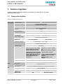
3.1 General description ................................................................................................. 7
3.2 Certification and standards ..................................................................................... 8
4
Hardware migration........................................................................................................ 9
4.1 Introduction .............................................................................................................. 9
4.2 Operating Modes ................................................................................................... 10
4.3 Interface/connectors comparison TC35i/TC35..................................................... 11
4.4 Power Supply ........................................................................................................ 12
4.4.1 General ...................................................................................................... 12
4.4.2 Power up / down scenarios....................................................................... 13
4.4.3 Automatic shutdown.................................................................................. 13
4.4.3.1 Temperature dependent shutdown......................................................... 13
4.4.4 Battery pack............................................................................................... 14
4.5 RTC backup .......................................................................................................... 15
4.6 Control signals....................................................................................................... 15
4.7 Interfaces ............................................................................................................... 16
4.7.1 Serial Interface........................................................................................... 16
4.7.2 SIM card interface...................................................................................... 16
4.7.3 Antenna Interface....................................................................................... 17
4.7.3.1 General .................................................................................................... 17
4.7.4 Audio Interface........................................................................................... 17
4.8 Electrostatic discharge.......................................................................................... 18
4.9 Mechanical Dimensions ........................................................................................ 18
4.10 Mounting and installation ....................................................................................... 19
4.11 Terms and Abbreviations ...................................................................................... 20
5
AT-Commands migration ............................................................................................. 22
5.1 General comments................................................................................................ 22
5.2 List of jointly supported AT-commands................................................................. 23
5.2.1 Standard V.25ter AT Commands .............................................................. 23
5.2.2 AT Commands for FAX ............................................................................. 24
5.2.3 AT Commands originating from GSM 07.07 ............................................. 25
5.2.4 AT commands originating from GSM 07.05 for SMS ................................ 27
5.2.5 Siemens defined AT commands for enhanced functions......................... 31
5.3 List of new AT-Commands ................................................................................... 32
5.3.1 AT Commands for SIM Application Toolkit (GSM 11.14) .......................... 32
5.3.2 AT Commands originating from GSM 07.07 ............................................. 32
5.3.3 Commands from change requests TC/AC/MC35 .................................... 33
5.3.4 New features for TC35i only – misc.......................................................... 33
5.3.5 Siemens defined AT commands for enhanced functions......................... 33
5.4 List of unsupported AT-Commands ...................................................................... 33
5.5 List of AT-Commands for V.25ter compatibility .................................................... 33
TC35_TC35i_MIG_01_V01.01
29.1.2003
Page 3 of 34
TC35i: Migration from TC35 to TC35i
PRELIMINARY
Figures
Figure 1: RTC supply from capacitor for TC35i ................................................................................. 15
Figure 2: RTC supply from capacitor for TC35.................................................................................. 15
Figure 3: TC35 footprint ................................................................................................................. 18
Figure 4: TC35i footprint ................................................................................................................ 18
Tables
Table 3-1: General description a)...................................................................................................... 7
Table 3-2: General description b)...................................................................................................... 8
Table 4-1: Operating modes ........................................................................................................... 10
Table 4-2: Host interface PIN assignment - ZIF connector................................................................. 11
Table 4-3: Power supply signals..................................................................................................... 12
Table 4-4: Power consumption comparison ..................................................................................... 12
Table 4-5: Maximum ratings and the associated URCs..................................................................... 13
Table 4-6: Wake up from SLEEP mode scenarios............................................................................ 14
Table 4-7: Battery specifications - general....................................................................................... 14
Table 4-8: Battery specifications - charging ..................................................................................... 14
Table 4-9: RS232 – Serial interface................................................................................................. 16
Table 4-10: RF interface ................................................................................................................ 17
Table 4-13: Glossary of terms ........................................................................................................ 20
Table 5-1: Standard V.25ter AT commands ..................................................................................... 23
Table 5-2: AT commands for FAX................................................................................................... 24
Table 5-3: AT commands from GSM 07.07...................................................................................... 25
Table 5-4: AT commands for SMS.................................................................................................. 27
Table 5-5: Siemens defined AT commands...................................................................................... 31
Table 5-6: AT commands for SAT................................................................................................... 32
Table 5-7: AT commands from GSM 07.07- new .............................................................................. 32
Table 5-8: AT commands from change requests .............................................................................. 33
Table 5-9: New TC35i features........................................................................................................ 33
Table 5-10: New Siemens defined AT commands............................................................................. 33
Table 5-11: V.254ter compatibility commands ................................................................................. 33
TC35_TC35i_MIG_01_V01.01
29.1.2003
Page 4 of 34
TC35i: Migration from TC35 to TC35i
PRELIMINARY
1
Revision history
Date
Author
Version
021022
LR
00.01
Initial version based on M20T to TC35T migration paper and "Daphne" HW
specification 00/011.
Done
021023
LR
00.02
Chapter # 5: AT commands - analysis and breakdown per module
Done
021023
NK
00.02
Initial version revision, AT Commands analysis
Done
021023
NK
00.03
Chapters # 3.1 – 4: HW
Done
021023
LR
00.03
Chapters # 3.1 – 4: HW – revision, Chapter # 2.1: How to use this
document - revision
Done
021024
LR
00.03
Chapter # 5: AT-Commands migration – revision, Chapters # 2.1, 5.1,
5.2.1
Done
021024
NK
00.03
Chapters # 4: HW
Done
021025
LR
00.03
Chapter # 5.6: AT-Commands reference documents – new, Chapters #
5.2.2, 5.2.3
Done
021025
NK
00.03
Chapters # 4: HW
Done
021028
LR
00.03
Chapter # 5.2.4: AT commands originating from GSM 07.05 for SMS
Done
021028
NK
00.03
Chapters # 4: HW
Done
021029
LR
00.03
Chapter # 5.2.5: Siemens defined AT commands for enhanced functions
Done
021029
NK
00.03
Chapters # 3.1 – 4: HW
Done
021030
LR
00.03
Chapters # 5.3, 5.4, 5.5, 5.6
Done
021030
NK
00.03
Chapter # 3: Feature migration
Done
021104
NK
00.04
Chapter # 4: Hardware migration [all sub chapters] - revision
Done
021104
LR
00.04
Chapters [all]: Integration of HW & SW part, additional formatting and
corrections
Done
021108
LR
00.05
Chapters [all]: Additional formatting and corrections
Done
021108
NK
00.05
Chapter #4: HW - revision, additional content
Done
021111
LR
00.05
Chapters [all]: Final formatting and corrections
Done
021111
AM
00.05
Chapters [all]: revision
Done
021112
AM/NK/LR
00.05
Chapters [all]: revision via telephone conference
Done
021112
NK/LR
00.06
Chapters [all]: corrections
Done
021112
NK
00.06
Chapters #: 4.6.3, 4.6.3.1, 4.7, 4.10
Done
021112
LR
00.06
Revision and corrections - latest info from TC35i_HD_01_V00.01 included
Done
021114
LR
00.07
Additional formatting and corrections
Done
021121
LR
00.08
Corrections, new "general notes" chapter
Done
021216
NK
00.09
Reducing the document to get a shorter version; additional formatting and
corrections trough the hole document
Done
021217
NK
00.09
Reducing the document to get a shorter version; additional formatting and
corrections trough the hole document
Done
021219
AM/LR
00.10
Revision, phone conference
Done
01.00
Released
Done
090103
TC35_TC35i_MIG_01_V01.01
Change
29.1.2003
Comment
Page 5 of 34
TC35i: Migration from TC35 to TC35i
PRELIMINARY
2
2.1
General info
How to use this document
The target audiences for this document are all categories of software and hardware
developers, system integrators and expert end-users of SIEMENS GSM wireless modules.
The content applies in particular to current users and developers whose applications are
utilizing SIEMENS TC35/TC37/TC35T for their communications purposes.
The aim of this document is to provide information and offer support in order to facilitate the
transition towards the new generation of SIEMENS wireless modules, namely, TC35i.
Information provided here is based on official technical manuals and released specifications
for TC35 and TC35i. The naming conventions used in this document follow those of source
documentation.
The authors presume the readers are already familiar with the contents of those manuals.
The document presents migration issues in detail using comparison tables between the
modules and covers topics ranging from hardware specifications to AT-command interface.
Technical specifications and interfaces to GSM telecom services are described and
compared in detail as well as all the relevant features. AT-command interface was given
particular attention since it represents the main tool available to developers through which
applications can be controlled. Available commands for both TC35i and TC35T are listed and
classified according to their implementation within each of the modules. Differences in test,
query and execution syntax as well as in available parameters are noted for each command.
Commands are classified in three main groups: jointly supported commands, commands
new with respect to TC35 and TC35 commands not supported by TC35i.
TC35_TC35i_MIG_01_V01.01
29.1.2003
Page 6 of 34
TC35i: Migration from TC35 to TC35i
PRELIMINARY
3
Feature migration
Feature comparison for both modules is introduced in the table below. Only main
specifications are listed.
3.1
General description
Table 3-1: General description a)
Features
Product Data
Parameter
TC35
Frequency bands:
TC35i
Dual-band EGSM 900, GSM1800
compliant to GSM Phase 2/2+
Output performance:
Class 4 (2W) for EGSM900
Class 1 (1W) for GSM1800
GSM Class:
Control:
Supported SIM card:
small MS
via AT commands
3V
External SIM card holder has to be connected via SIM interface connector
SM, FD, LD, MC, RC, ON, ME
not supported
supported, via AT%D
Phonebook management:
Automatic dial on DTR
line activation:
Input voltage range:
Component mounting:
Dimensions:
Weight:
Temperature conditions:
Real time clock:
Audio
Timer function:
Antenna design:
Antenna connectors:
Evaluation kit:
Speech codec:
SMS
Audio interface:
General
SAT
bulk SMS MO
enhancement:
SMS storages:
SIM Application Toolkit:
TC35_TC35i_MIG_01_V01.01
3.3V – 5.5V
3.3 – 4.8 V
Automatic shutdown supported
both sides
single-side mounted
54.5 x 36 x 6.85 mm
54,5 x 36 x 3,6
18g
10g
Normal operation: (-20°C; +55°C)
Restricted operation: (-29°C; -25°C) & (+55°C; +70°C)
Storage: (-40°C; +85°C)
Automatic shutdown supported: (>+75°C and <-29°C)
Implemented
Pin 30, VDDLP
Pin 30, VDDLP
Needs an external serial resistor Includes 1kΩ resistor on VDDLP
between VDDLP and capacitor /
line
battery to limit input current.
between ZIF connector and PSU.
No
If application is battery powered, external resistor required.
additional diode(s) are suggested
between VDDLP and VBATT+ (see If used in earlier TC35 application,
Chapter "RTC backup" in your
removing additional diode(s)
"TC3x Hardware Interface
between
Description").
VDDLP and VBATT+ line is
required.
Programmable via AT command
50Ω antenna interface.
GSC coaxial connector
DSB 35 Support Box
Half Rate (ETS 06.20)
Full Rate (ETS 06.10)
Enhanced Full Rate (ETS 06.50 / 06.60 / 06.80)
2 x analogue audio interfaces (hands-free, supports echo cancellation)
Point-to-point MT and MO SMS
SMS Cell Broadcast
Text and PDU mode SMS MO
+CMMS
SM
-
29.1.2003
SM+ME (25 places)
SAT class 3, GSM 11.14 Release 98
Page 7 of 34
TC35i: Migration from TC35 to TC35i
PRELIMINARY
Table 3-2: General description b)
Features
Parameter
Data
Supported services:
Fax
External
interfaces
Serial interface
USSD support:
Connection element:
Supported classes:
RF interface:
Application interface:
Baud rate:
TC35
2400 bps (V.22bis)
4800 bps (V.32)
9600 bps (V.32)
14400 bps (V.34)
2400 bps (V.110)
4800 bps (V.110)
9600 bps (V.110)
14400 bps (V.110)
supported
non-transparent mode
Group 3: Class 1, Class 2
GSC antenna connector only
40-pin ZIF connector
Fixed range
(300bps...115kbps)
Autobauding
(1.2kbps...115kbps)
Local character framing: 8N1 - fixed
Multiplex mode:
Flow control:
Fixed range (300bps...230kbps)
Autobauding (1.2kbps...230kbps)
7E1, 7O1, 8E1, 8N1, 8O1, 7E2, 7O2,
8E2, 8N2, 8O2; via AT command
supported, MUX GSM 07.10
RTS/CTS hardware handshake and software XON/XOFF flow control.
Software update
3.2
TC35i
via RS232 or SIM interface
Certification and standards
Both TC35 and TC35i comply to the same directives and standards. For further information,
please consult the HW manual.
TC35_TC35i_MIG_01_V01.01
29.1.2003
Page 8 of 34
TC35i: Migration from TC35 to TC35i
PRELIMINARY
4
Hardware migration
This chapter contains information regarding the hardware set-up, installation instructions and
physical properties for both modules. Hardware features are listed in comparison tables
related to power supply, RF, audio, SIM and RS232 serial interfaces with functionality
descriptions. All features, except RF, are available through common host application
interface.
4.1
Introduction
TC35i was intended as a "feature-superset" successor to TC35. It is super-slim, single-side
mounted, compact, dual-band GSM OEM module for integration into industrial or mobile
devices.
TC35i incorporates all the TC35 HW features with following additional features:
æ
æ
æ
æ
æ
Automatic dial on DTR line activation
Autobauding up to 230kbps. Character framing and flow control fully supported
Single side mounted
SM+ME (25 places)
SAT class 3, GSM 11.14
TC35_TC35i_MIG_01_V01.01
29.1.2003
Page 9 of 34
TC35i: Migration from TC35 to TC35i
PRELIMINARY
4.2
Operating Modes
Various operating modes for TC35 and TC35i modules are listed in the table below. TC35i
module supports four additional sleep modes compared to TC35. For further details please
consult the TC35i manual
The table below shows operating modes overview for both devices
Table 4-1: Operating modes
Mode
Function
GSM SLEEP
Normal
operation
GSM IDLE
GSM TALK
POWER DOWN
Alarm mode
Charge-only
mode
Charge mode
during normal
operation
TC35
TC35i
Power saving mode set with AT+CFUN
command. Software is active to minimum
extent. If the GSM engine was
registered to the GSM network in IDLE
mode, it is registered and paging in
SLEEP mode, too. AT interface is not
responding.
Software is active to a minimum extent. If the
module was registered to a GSM network in
IDLE mode, it remains, in SLEEP mode,
registered and pageable from the BTS.
Power saving can be chosen at different levels.
The NON_CYCLIC SLEEP mode (AT+CFUN=0)
disables the AT interface. The CYCLIC SLEEP
mode AT+CFUN=5, 6, 7 and 8 alternatingly
activate and deactivate the AT interface to
allow permanent access to all AT commands.
Software is active. Once registered to the GSM network, paging with BTS is carried out.
The module is ready to send and receive.
Connection between two subscribers is in progress. Power consumption depends on
network coverage individual settings, such as DTX off/on, FR/EFR/HR, hopping sequences,
antenna.
Operating voltage is applied. Only a voltage regulator in the Power Supply ASIC is active
for powering the RTC. Software is not active. The RS-232 interface is not accessible.
Restricted operation launched by RTC alert function while the module is in Power Down
mode. Module will not be registered to GSM network. Limited number of AT commands is
accessible. If application is battery powered: No charging functionality in Alarm mode.
Limited operation for battery powered applications. Enables charging while engine is
detached from GSM network. Limited number of AT commands is accessible. There are
several ways to launch Charge-only mode:
æ From Power Down mode: Connect charger to POWER lines when engine was powered
down by AT^SMSO.
æ From Normal mode: Connect charger to POWER lines, then enter AT^SMSO.
Normal operation (SLEEP, IDLE, TALK, DATA) and charging running in parallel. Charge
mode changes to Charge-only mode when the module is powered down before charging
has been completed.
TC35_TC35i_MIG_01_V01.01
29.1.2003
Page 10 of 34
TC35i: Migration from TC35 to TC35i
PRELIMINARY
4.3
Interface/connectors comparison TC35i/TC35
TC35 and TC35i are equipped with a 40-pin 0.5mm pitch ZIF connector that connects to the
cellular application platform. The mentioned ZIF connector is completely the same for both
devices. The host interface incorporates several sub-interfaces described in the following
chapters
TC35 and TC35i are totally PIN compatible. Some off the TC35 signal names were
changed with TC35i but the functionality is completely identical.
Table 4-2: Host interface PIN assignment - ZIF connector
Pin No.
Function
Signal Name
IO
TC35
1-5
6-10
11-12
13
14
15
16
17
18
19
20
21
22
23
24
25
26
27
28
29
30
31
32
33
34
35
36
37
38
39
40
Power supply
Ground
Charger
External supply voltage
Battery Temperature
Ignition
RS232
RS232
RS232
RS232
RS232
RS232
RS232
RS232
SIM
SIM
SIM
SIM
SIM
SIM
RTC Backup
Power Down
Synchronization
Audio
Audio
Audio
Audio
Audio
Audio
Audio
Audio
TC35_TC35i_MIG_01_V01.01
I
Ground
I
O
I
I
O
O
O
I
O
I
I
0
I
O
IO
O
O
Ground
O
I
O
O
O
O
O
I
I
I
I
VBATT+
GND
POWER
VDD
AKKU_TEMP
/IGT
DSR0
/RING
RxD0
TxD0
CTS0
RTS0
DTR0
DCD0
CCIN
CCRST
CCIO
CCCLK
CCVCC
CCGND
VDDLP
/PD
SYNC
EPP2
EPN2
EPP1
EPN1
MICP1
MICN1
MICP2
MICN2
29.1.2003
TC35i
BATT+
GND
POWER
VDD
BATT_TEMP
IGT
DSR0
RING0
RxD0
TxD0
CTS0
RTS0
DTR0
DCD0
CCIN
CCRST
CCIO
CCCLK
CCVCC
CCGND
VDDLP
EMERGOFF
SYNC
EPP2
EPN2
EPP1
EPN1
MICP1
MICN1
MICP2
MICN2
Page 11 of 34
TC35i: Migration from TC35 to TC35i
PRELIMINARY
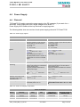
4.4
Power Supply
4.4.1 General
TC35 and TC35i need to connect the power supply to the ZIF connector (5 pins each VBATT+
and GND). Power supply has to be a single voltage source at BATT+.
Power Supply ASIC handles all the key functions for supplying power.
The following tables show an overview of main power supply points with TC35 and TC35i
Table 4-3: Power supply signals
General
Feature
TC35
Input voltage range:
Ignition:
TC35i
Five pins of BATT+ and GND must be
switched in parallel for supply purposes
because peaks of up to 2A may occur.
VI = 3.3V to 5.5V
VI,typ = 4.2V
Inom ˜ 2A, in burst
Five pins of BATT+ and GND must be switched
in parallel for supply purposes because peaks of
up to 3A may occur.
VI = 3.3V to 4.8V
VI,typ = 4.2V
Inom ˜ 2A, in burst
Vout = 2.3V
Rout ≈ 220k.
Vlow,max = 0.45V @ Iout = 10µA
tlow ≈ 100ms
Signal: falling edge and hold for t low
RI ˜ 100kΩ, C I ˜ 1nF
VILmax = 0.5V @ Imax = 20µA
VOpenmax = 2.3V
tlow ≈ 100ms
Signal: falling edge and hold for t low
Open drain/collector driver is required to
pull down this pin to power on the GSM
Engine.
ON
~~~
|____|~~~ Active Low ≥ 100ms
Emergency shutdown:
Via /PD (pin no. 31)
via EMERGOFF (pin no. 31)
(Watchdog)
This line must be driven by an Open Drain
or Open Collector driver.
Emergency shutdown deactivates the
modules power supply.
This line must be driven by an Open Drain or
Open Collector driver.
Emergency shutdown deactivates the modules
power supply.
Signal
3.5s
~~~
|______|~~~ Active Low ≥
Signal
~~~
|______|~~~ Active Low ≥ 3.2s
Synchronization:
Indication of increased current
consumption during uplink
transmission burst
Vout,low,max = 0.2V @ I= 0.1mA
Vout,high,min = 2.25V @ I=-0.1mA
Vout,high,max = 2.76V
VOLmax = 0.3V @ I = 0.1mA
VOHmin = 2.25V @ I = -0.1mA
VOHmax = 2.73V
Power saving:
Supported trough AT+CFUN
Supported trough AT+CFUN
Functionality levels <fun>=0, 5 , 6, 7 and
8
Functionality levels <fun>=0
Table 4-4: Power consumption comparison
Power consumption
Device
Stand-by
Sleep
Idle
Talk mode at
EGSM900/1800
Talk mode (peak) at
EGSM900/1800
TC35
50µA typ
3mA typ
10mA typ
300mA/270mA
1.8A typ
TC35i
50µA typ
3mA typ
25mA
300-400mA
2A typ
TC35_TC35i_MIG_01_V01.01
29.1.2003
Page 12 of 34
TC35i: Migration from TC35 to TC35i
PRELIMINARY
4.4.2 Power up / down scenarios
TC35 and TC35i are fully identical regarding the power up/down scenario with the following
exception:
To actually turn off the TC35i, the emergency shutdown line has to be driven to ground for ≥
3.2s. The TC35 emergency shutdown line needs to be driven to ground for ≥ 3.5s
For further information please consult the HW manual for TC35 and TC35i.
4.4.3 Automatic shutdown
To ensure proper operation of all assemblies under varying conditions, such as temperature,
input voltage, transmission power etc., TC35 and TC35i features protection elements for
automatic shutdown.
Automatic shutdown takes effect if:
• the TC35/TC35i board is exceeding the critical limits of overtemperature or
undertemperature
• the battery is exceeding the critical limits of overtemperature or undertemperature in a
battery application, undervoltage is detected
• overvoltage is detected.
4.4.3.1
Temperature dependent shutdown
The board temperature is constantly monitored by an internal NTC resistor located on the
PCB. The NTC that detects the battery temperature must be part of the battery pack circuit as
described in the manual. The values detected by NTC resistor are measured directly on the
board and the battery and are therefore, not fully identical with the ambient temperature.
Table 4-5: Maximum ratings and the associated URCs
Sending temperature alert
TC35
TC35i
^SCTM_A: 1
Caution: Tamb of battery between +56°C and +60°C.
^SCTM_B: 1
Caution: Tamb of board between +55°C and +75°C.
^SCTM_A: -1
Caution: Tamb of battery between -14°C and -18°C.
^SCTM_B: -1
Caution: Tamb of board between –20°C and –25°C.
^SCTM_A: 0
Battery back to uncritical temperature range
^SCTM_B: 0
Caution: Tamb of board between +65°C and
+75°C.
Caution: Tamb of board between –25°C and –
29°C.
Board back to uncritical temperature range.
Automatic shutdown (URC appears no matter whether or not presentation was enabled)
^SCTM_A: 2
Alert: Tamb of battery >60°C. TC35 switches off
immediately.
^SCTM_B: 2
Alert: Tamb of board >70°C. TC35 switches off
immediately.
^SCTM_A: -2
Alert: Tamb of battery < -18°C. TC35 switches off
immediately
TC35_TC35i_MIG_01_V01.01
29.1.2003
Alert: Tamb of board >75°C. TC35i switches off
immediately.
Page 13 of 34
TC35i: Migration from TC35 to TC35i
PRELIMINARY
^SCTM_B: -2
Alert: Tamb of board <-25°C. TC35i switches off
immediately.
Alert: Tamb of board <-29°C. TC35i switches off
immediately.
The table below shows which conditions will wake up TC35 and TC35i from sleep mode
As it can be seen from the following table TC35i supports four sleep modes (5,6,7,8)
more then TC35.
Table 4-6: Wake up from SLEEP mode scenarios
AT+CFUN=0 ⇒
AT+CFUN=1
Event
TC35
Ignition line
/RTS0 or /RTS1 (falling edge)
Unsolicited Result Code (URC)
Incoming voice or data call
Any AT command (incl. outgoing voice or
data call, outgoing SMS)
Incoming SMS depending on mode
selected by AT+CNMI:
AT+CNMI=0,0
(= default, no indication of received SMS)
AT+CNMI=1,1
(= displays URC upon receipt of SMS)
TC35i
No
Yes
Yes
Yes
Not Possible
(UART disabled)
AT+CFUN=5 or 6 ⇒
AT+CFUN=1
AT+CFUN=7 or 8 ⇒
AT+CFUN=1
TC35i only - (TC35 does not support sleep modes: 5-8)*
TC35i
No
No
No
No
Yes
No
Yes
No
No
No
No
No
No
Yes
Yes
No
RTC alarm
AT+CFUN=1
Yes
Yes
No
Not Possible
Yes
Yes
(UART disabled)
* TC35i supports SLEEP modes 0, 5, 6, 7 and 8. Different events or commands cause a wake-up from a SLEEP mode. The
detailed descriptions of these modes can be found in respective HID documents.
4.4.4
Battery pack
For some applications the use of a battery pack may be required. TC35 and TC35i can be
powered from a Li-Ion battery:
Table 4-7: Battery specifications - general
General
TC35
Supported Charging Technique
Operating modes
Output voltage (for charger)
Charging current
Maximum voltage spikes
TC35i
Trickle charging and processor controlled fast charging
SLEEP, IDLE or TALK/DATA mode
5.5V...8V (under load)
Limited to 500mA
25V and must not exceed 1ms
15V and must not exceed 1ms
Table 4-8: Battery specifications - charging
Module
TC35
TC35i
Battery specification
3.6 V
3.6 V
TC35_TC35i_MIG_01_V01.01
Maximum charging voltage
4.2 V
4.2 V
Capacity
600-800 mAh
max 850 mAh
29.1.2003
Page 14 of 34
TC35i: Migration from TC35 to TC35i
PRELIMINARY
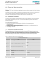
4.5
RTC backup
The internal Real Time Clock of is supplied from a dedicated voltage regulator in the power
supply ASIC which is also active when TC35 and TC35i are in POWER DOWN status. Alarm
function is included that allows waking up TC35 and TC35i without logging to the GSM
network.
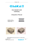
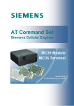
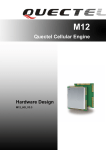
On the TC35i board a serial resistor is placed next to the VDDLP line in order to limit
the input current of an empty capacitor. This eliminates the need of adding a resistor
as required in applications based on the earlier TC35 module.
On the TC35 board there is no resistor placed on the board and it should be added when
designing the GSM application
BATT+
Baseband
processor
ZIF
PSU
1k
RTC
VDDLP
+
Figure 1: RTC supply from capacitor for TC35i
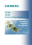
Figure 2: RTC supply from capacitor for TC35
4.6
Control signals
Input and Output control signals are identical with both TC35 and TC35i device.
For further information please consult the HW manual for TC35 and TC35i.
TC35_TC35i_MIG_01_V01.01
29.1.2003
Page 15 of 34
TC35i: Migration from TC35 to TC35i
PRELIMINARY
4.7
Interfaces
TC35 and TC35i interfaces are compatible. The following chapters shows a detailed
comparison values for each interface. For further information please consult the TC35i HW
manual
4.7.1 Serial Interface
Each device uses the same serial interface type with identical pin positions.
Compared to TC35 module that supports a fixed local character framing format between TA
and TE, the new TC35i device offers various character framing formats specified in the next
table. For further information please consult the AT command migration part of the document
or the TC35i at command specification.
The table below shows a comparison of values for the serial interface with both devices.
Table 4-9: RS232 – Serial interface
RS232 - Serial interface
Feature
Type:
Signal levels:
Local character framing:
Selectable baud rate
Flow Control
TC35
TC35i
Serial asynchronous transmitter and receiver conforming to ITU-T RS232 Interchange Circuits DCE.
Vout,low,max = 0.2V @ I = 0.1mA
VOLmax = 0.3V @ I = 0.1mA
Vout,high,min = 2.25V @ I = -0.1mA
VOHmin = 2.25V @ I = -0.1mA
Vout,high,max = 2.76V
VOHmax = 2.73V
Vin,high,min = 1.95V, Vi,h,max=3.3V
VIHmin = 1.95V, VIHmax = 3.45V
7E1, 7O1, 8E1, 8N1, 8O1, 7E2, 7O2, 8E2, 8N2,
fixed to 8 data bits, no parity and 1 stop bit
8O2
Fixed range (300bps...115kbps)
Fixed range (300bps...230kbps)
Autobauding (1.2kbps...115kbps)
Autobauding (1.2kbps…230kbps)
RTS0 / CTS0 and/or software flow control via XON / XOFF.
4.7.2 SIM card interface
There are no changes on the integrated SIM interface with TC35 and TC35i.
For further information please consult the HW manual for TC35 and TC35i.
TC35_TC35i_MIG_01_V01.01
29.1.2003
Page 16 of 34
TC35i: Migration from TC35 to TC35i
PRELIMINARY
4.7.3 Antenna Interface
4.7.3.1
General
Both devices TC35 and TC35i use a GSC connector to establish the RF connection to the
host application. The table below shows a RF interface overview for each device.
Table 4-10: RF interface
RF interface - general
Feature
TC35
TC35i
Antenna connector:
GSC coaxial connector
Interface type:
GSM 900/1800
Max RF power:
2W [EGSM900] / 1W [GSM1800]
RF
Min
Input sensitivity @ ARP
-104 [EGSM900]
-102dBm [EGSM900, GSM1800]
-102 [GSM1800]
BER Class II < 2.4%
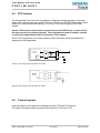
4.7.4 Audio Interface
Both TC35 and TC35i comprise two analogue audio interfaces, each with an analogue
microphone input and an analogue loudspeaker output (see block diagram below).
To suit several types of equipment, there are several audio modes available which can be
selected with the AT^SNFS command. The electrical characteristics of the voiceband part
vary with the audio mode. For example, sending and receiving amplification, sidetone paths,
noise suppression etc. depend on the selected mode and can be set with AT commands
(except for mode 1).
All analogue microphone inputs and loudspeaker outputs are balanced. A power supply for
electret microphones is implemented in both interfaces, too. If not needed, they have to be
decoupled with capacitors.
Detailed instructions on using AT commands are presented in the AT Command Manual.
TC35i only: Independently of the audio mode, analogue interfaces 1 or 2 can be
selected and configured by AT commands.
Characteristics of audio modes
The electrical characteristics of the voiceband part depend on the current audio mode, set
with AT^SNFS command. Voice band characteristics are the same for TC35 and TC35i. For
further details please consult the HW manual.
TC35_TC35i_MIG_01_V01.01
29.1.2003
Page 17 of 34
TC35i: Migration from TC35 to TC35i
PRELIMINARY
4.8
Electrostatic discharge
TC35 and TC35i are identical protected against Electrical Discharge. For additional
information about ESD please consult the actual specification
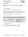
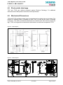
4.9
Mechanical Dimensions
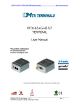
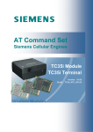
TC35 and TC35i provide the same type of connectors and mounting holes on the board. The
position of mounting holes is identical as with TC35, as well as the order of external
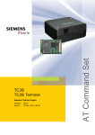
connectors. The outline mechanical dimensions are identical with both devices except the
high. TC35i is a single side mounted device that makes it much thinner compared to TC35.
Figure 3: TC35 footprint
Figure 4: TC35i footprint
TP GND
TP BATT+
TC35_TC35i_MIG_01_V01.01
29.1.2003
Page 18 of 34
TC35i: Migration from TC35 to TC35i
PRELIMINARY
4.10 Mounting and installation
Appropriate installation and mounting to the host housing / enclosure is essential for reliable
operation of the GSM engine.
TC35i & TC35
The TC35 board provides three mounting holes. To properly mount it to the host device you
can use M1.6 or M1.8 screws plus suitable washers. The maximum diameter of the screw
head, including the washer, must not exceed 4 mm.
To prevent mechanical damage, be careful not to force, bend or twist the GSM engine. Make
sure it is positioned flat against the host device.
Avoid placing the TC35 board tightly to the host device. Instead, it is recommended
to set the spacers between the module and the host device. If your design approach does not
allow for spacers make sure the host device provides an opening for the RF part.
Avoid exerting any pressure on the shielding covers. Contact springs or other components
must not be fastened to the covers. In extreme conditions, you run the risk of short-circuit if
the cover was damaged or distorted due to pressure. Furthermore, the covers must not be
used to apply any solder joints.
For snap-in concept please be aware that the TC35i PCB is thinner then the TC35
PCB
TC35_TC35i_MIG_01_V01.01
29.1.2003
Page 19 of 34
TC35i: Migration from TC35 to TC35i
PRELIMINARY
4.11 Terms and Abbreviations
Table 4-11: Glossary of terms
A/D
AF
AFC
AGC
AMR
ARP
ASIC
BB
CPU
CR
CTR
DAI
DFC
DSB
DSP
DSR
DTR
DTX
EFR
EMC
E-GAIM
EGSM
ESD
ESR
ETS
FE
FFC
FR
GAIM
GMSK
GSC
GSM
HR
HW
IC
IF
IMEI
I/O
ISO
ITU
LDO
LFBGA
Li-Ion
LNA
LO
Mbps
MMI
MTBF
NTC
OC
OTP
PA(C)
PCB
PCM
PGC
PLL
PSU
RAM
RF
RI
ROM
RTC
Rx
SAW
Analogue-to-Digital Converter
Audio Frequency
Automatic Frequency Control
Automatic Gain Control
Adaptive Multi Rate
Antenna Reference Point
Application Specific Integrated Circuit
Baseband
Central Processing Unit
Change Request
Common Technical Regulation
Digital Audio Interface
Digital Frequency Centering
Development Support Board
Digital Signal Processor
Data Set Ready
Data Terminal Ready
Discontinuous transmission
Enhanced Full Rate
Electro Magnetic Compatibility
Enhanced GSM Analog Interfacing Module
Enhanced GSM
Electrostatic Discharge
Equivalent Serial Resistance
European Telecommunication Standard
Front End
Flat Flexible Cable
Full Rate
GSM Analogue Interface Module
Gaussian Minimum Shift Keying
(Type of antenna connector)
Global Standard for Mobile Communications
Half Rate
Hardware
Integrated Circuit
Intermediate Frequency
International Mobile Equipment Identity
Input/Output
International Standards Organization
International Telecommunications Union
Low Drop Out
Low-Profile Fine-Pitch Ball Grid Array
Lithium-Ion
Low-Noise Amplifier
Local Oscillator
Mbits per second
Man Machine Interface
Mean Time Between Failures
Negative Temperature Coefficient
Offset Compensation
One Time Programmable
Power Amplifier (Control)
Printed Circuit Board
Pulse Code Modulation
Programmable Gain-Controlled Amplifier
Phase Locked Loop
Power Supply Unit
Random Access Memory
Radio Frequency
Ring Indication
Read-Only Memory
Real-Time Clock
Receive direction
Surface Acoustical Wave Filter
TC35_TC35i_MIG_01_V01.01
29.1.2003
Page 20 of 34
TC35i: Migration from TC35 to TC35i
PRELIMINARY
SELV
SIM
SMS
SW
TBR
TBD
TBI
TDD
TDMA
Tx
UART
VCO
VCXO
VSWR
ZIF
Safety Extra Low Voltage
Subscriber Identification Module
Short Message Service
Software
Technical Based Regulation
To Be Defined
To Be Inserted
Time Division Duplex
Time Division Multiple Access
Transmit direction
Universal Asynchronous Receiver Transmitter
Voltage Controlled Oscillator
Voltage Controlled Quartz Oscillator
Voltage Standing Wave Ratio
Zero insertion force (connector)
TC35_TC35i_MIG_01_V01.01
29.1.2003
Page 21 of 34
TC35i: Migration from TC35 to TC35i
PRELIMINARY
5
AT-Commands migration
TC35i was intended as a "feature-superset" successor to TC35.
AT Cellular command structure for TC35i corresponds to that of TC35 with the added
improvements and new features.
Available commands for both TC35i and TC35 are listed and classified according to their
implementation within each of the modules. The entire command set of TC35 is supported by
TC35i. Differences in test, query and execution syntax as well as in available parameters are
noted for each command. Commands are classified in three main groups:
æ
æ
æ
5.1
jointly supported commands
commands new with respect to TC35 and
TC35 commands not supported by TC35i
General comments
TC35i feature highlights
The commands below are either newly introduced or improvements based on the
implementations present with other modules, e.g. M20, AC43/45, MC35.
æ
æ
æ
æ
æ
æ
æ
æ
æ
æ
æ
AT+ICF, AT+IFC - TC35i re-introduces these commands that were present in M20 but not in
TC35 - character framing and flow control commands:
AT%D - Command also previously available in M20 - automatic dialling by DTR toggle was not
supported by TC35
ATS0 now applies to incoming voice calls as well
AT+CMER, AT+CIND: mobile event reporting commands
AT^SRTC – incoming SMS ring indication
AT+CPBS - Extended ME phonebook up to 250 entries
AT&W – user profile extended - new commands added: AT+ICF, AT+IFC, AT\Qn, AT%D
AT+CMMS – keeps the data channel open for much faster throughput of SMS-SUBMIT
messages
AT+CNMA is no longer required for SMS-DELIVER messages delivered directly to TE
AT^SSR - issues URCs related to availability of the SIM card
AT+CCUG – closed user group now available
TC35_TC35i_MIG_01_V01.01
29.1.2003
Page 22 of 34
TC35i: Migration from TC35 to TC35i
PRELIMINARY
5.2
List of jointly supported AT-commands
AT-commands listed in the tables below are supported by both TC35i and TC35. Command
defaults, however, may differ.
NOTE: Many commands are available only after the PIN has been entered. For a full list, please refer to
respective AT reference manuals.
5.2.1 Standard V.25ter AT Commands
Table 5-1: Standard V.25ter AT commands
#
AT
1 A/
2 +++
3 AT\Qn
Repeat previous command line
Switch from data mode to command mode
Flow control
Differing implementation
TC35i
4 ATA
5 ATD
TC35i
Command
AT\Qn included within user profile. See comments under AT&W.
TC35
-
Answer a call
Mobile originated call to dial a number
Differing implementation
International calls to be dialled exclusively starting with "+", i.e. "00" at the beginning of a
dialling string will not be translated into a "+".
TC35
-
6
7
8
9
10
11
ATD><mem><n> Originate call to phone number <n> in memory <mem>
ATD><n>
Originate call to phone number selected from active memory
ATD><str>
Originate call to phone number in memory with corresponding field
ATDI
Mobile originated call to dialable ISDN number <n>
ATDL
Redial last telephone number used
ATE
Enable command echo
Differing parameters
TC35i
TC35
MUX: Echo is disabled at the start of MUX mode and
MUX: Echo is available on logical channels and is
is not available on logical channels, ATE1 responds
initially enabled only on main (data) MUX channel.
with ERROR
12
13
14
15
16
17
18
19
20
ATH
Disconnect existing connection
ATI
Display product identification information
ATI[value]
Display additional identification information
ATL
Set monitor speaker loudness
ATM
Set monitor speaker mode
ATO
Switch from command mode to data mod
ATQ
Set result code presentation mode
ATP
Select pulse dialling
ATS0
Set number of rings before automatically answering the call
Differing implementation
TC35i
TC35
ATS0 applies to incoming voice calls as well.
ATS0 applies only to incoming data or fax calls.
22
23
24
25
26
27
ATS2
ATS3
ATS4
ATS5
ATS6
ATS7
TC35i
28
29
30
31
ATS8
ATS10
ATS18
ATT
Escape code sequence
Write command line termination character
Set response formatting character
Write command line editing character
Set pause before blind dialling
Set number of seconds to wait for connection completion
Differing implementation
ATS7 applies to voice calls as well.
TC35
ATS7 applies only to data calls.
Set number of seconds to wait for comma dial modifier
Set disconnect delay after indicating the absence of data carrier
Extended error report
Select tone dialling
TC35_TC35i_MIG_01_V01.01
29.1.2003
Page 23 of 34
TC35i: Migration from TC35 to TC35i
PRELIMINARY
#
AT
Command
32
33
34
35
36
37
38
39
40
ATV
ATX
ATZ
AT&C
AT&D
AT&F
AT&S
AT&V
AT&W
Set result code format mode
Set CONNECT result code format and call monitoring
Set all current parameters to user defined profile
Set circuit Data Carrier Detect (DCD) function mode
Set circuit Data Terminal Ready (DTR) function mode
Set all current parameters to manufacturer defaults
Set circuit Data Set Ready (DSR) function mode
Display current configuration
Store current configuration to user defined profile
Differing parameters
TC35i
TC35
User profile extended to include the following
Commands: AT\V, AT+ICF, AT+IFC, AT\Q, AT%D
commands:
are either not available or not included within user
AT\V, AT+ICF, AT+IFC, AT\Q, AT%D, AT^STPB.
profile.
41
42
43
44
45
46
47
AT+GCAP
Request complete TA capabilities list
AT+GMI
Request manufacturer identification
AT+GMM
Request TA model identification
AT+GMR
Request TA revision identification of software status
AT+GSN
Request TA serial number identification (IMEI)
AT+ILRR
Set TE-TA local rate reporting
AT+IPR
Set fixed local rate
Differing parameters (factory defaults); minor wording differences
TC35i
<rate>
Factory settings, fixed: AT+IPR=57600
(230,4kbps possible in case of available memory)
TC35
<rate>
Factory settings, autobauding: AT+IPR=0
5.2.2 AT Commands for FAX
Table 5-2: AT commands for FAX
#
AT
48 AT+FBADLIN
49 AT+FBADMUL
50 AT+FBOR
51 AT+FCIG
52 AT+FCLASS
53 AT+FCQ
54 AT+FCR
55 AT+FDCC
Command
Bad Line Threshold
Error Threshold Multiplier
Query data bit order
Query or set the Local polling id
Fax: Select, read or test service class
Copy Quality Checking
Capability to receive
Query or set capabilities
TC35_TC35i_MIG_01_V01.01
29.1.2003
Page 24 of 34
TC35i: Migration from TC35 to TC35i
PRELIMINARY
#
AT
56 AT+FDFFC
57 AT+FDIS
58 AT+FDR
59 AT+FDT
60 AT+FET
61 AT+FK
62 AT+FLID
63 AT+FMDL
64 AT+FMFR
65 AT+FOPT
66 AT+FPHCTO
67 AT+FREV
68 AT+FRH
69 AT+FRM
70 AT+FRS
71 AT+FTH
72 AT+FTM
73 AT+FTS
74 AT+FVRFC
Command
Data Compression Format Conversion
Query or set session parameter
Begin or continue phase C data reception
Data Transmission
End a page or document
Kill operation, orderly FAX abort
Query or set the Local Id setting capabilities
Identify Product Mode
Request Manufacturer Identification
Set bit order independently
DTE Phase C Response Timeout
Identify Product Revision
Receive Data Using HDLC Framing
Receive Data
Receive Silence
Transmit Data Using HDLC Framing
Transmit Data
Stop Transmission and Wait
Vertical resolution format conversion
5.2.3 AT Commands originating from GSM 07.07
Table 5-3: AT commands from GSM 07.07
#
AT
Command
75 AT+CACM
Accumulated call meter (ACM) reset or query
76 AT+CALA
Set alarm time
Differing references to URC implementation in autobauding
TC35i
TC35
Indicates ME wake-up into Alarm mode:
Indicates ME wake-up into Alarm mode:
^SYSSTART ALARM MODE
^SYSSTART ALARM MODE
+CALA: <text>
+CALA: <text>
If autobauding is active (AT+IPR=0) the URCs
^SYSSTART ALARM MODE does not appear but
your individual <text> message will be displayed.
77
78
79
80
81
82
83
If autobauding is active (AT+IPR=0) the URCs
^SYSSTART ALARM MODE
and +CALA: <text> do not appear. Therefore,
avoid using Alarm mode in conjunction with
autobauding.
AT+CAMM
Accumulated call meter maximum (ACMmax) set or query
AT+CAOC
Advice of Charge information
AT+CBST
Select bearer service type
AT+CCFC
Call forwarding number and conditions control
AT+CCLK
Real Time Clock
AT+CEER
Extended error report
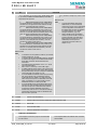
AT+CFUN
Set phone functionality
Differing parameters and notes
TC35_TC35i_MIG_01_V01.01
29.1.2003
Page 25 of 34
TC35i: Migration from TC35 to TC35i
PRELIMINARY
#
AT
TC35i
Command
<fun> parameter now accepts CYCLIC SLEEP MODE values
5, 6, 7 and 8, in addition to SLEEP MODE / FULL FUNCT.,
supported so far by TC35:
5
Reduced functionality (CYCLIC SLEEP MODE)
The serial interface is enabled with every "wake up". If
characters are recognized the serial interface will stay
active for 2 seconds (after last character).
6
Reduced functionality (CYCLIC SLEEP MODE)
The serial interface is enabled with every "wake up". If
characters are recognized the serial interface will stay
active for 10 minutes (after last character).Note: In any
case, any circuit switched calls will be terminated.
7
Reduced functionality (CYCLIC SLEEP MODE)
The serial interface is enabled with every "wake up". If
characters are recognized the serial interface will stay
active for 2 seconds (after last character). The sole
exception for wake up is at+cfun=1.
8
Reduced functionality (CYCLIC SLEEP MODE)
The serial interface is enabled with every "wake up". If
characters are recognized the serial interface will stay
active for 10 minutes (after last character). The sole
exception for wake up is at+cfun=1.
TC35
<fun> parameter accepts only values 0 and
1.
Additional notes
TC35
•
To check that ME has entered the
SLEEP mode, it is recommended to
measure the supply current. Depending
on the configuration of the SYNC pin,
the SLEEP mode may also be indicated
by a status LED (see "AT^SSYNC
Configure SYNC Pin", pg. 177).
•
When in SLEEP mode, the following
events may cause the ME to wake up:
incoming call, Real Time Clock alarm,
falling edge of RTS (RS-232, 2.65V
CMOS level) and receipt of an
unsolicited result code (URC, see
chapter 7.1.3).
Additional notes
TC35i
•
To check the current operation mode see „AT^SSYNC
Configure SYNC Pin", pg. 181.
•
To check if ME has entered SLEEP mode it is necessary
to measure the supply current. SLEEP mode actually
starts after remaining network activities were
terminated.
•
For SLEEP mode functionalities (<fun>=0, 5, 6) will
not work without PIN1.
•
After reset it is necessary to enter PIN1 again.
•
In SLEEP mode the device wakes up by incoming call,
short message, Real Time Clock alarm, falling edge of
RTS (RS-232 levels) and upon receipt of an unsolicited
result code (URC, see chapter 10.1.4).
•
In CYCLIC SLEEP mode device wakes up by incoming
call, short message (only if notification output is
configured using AT+CNMI=1,1), Real Time Clock
alarm and upon receipt of an unsolicited result code
(URC, see chapter 10.1.4). RTS signal is only for
handshake and does not wake up the ME.
•
In CYCLIC SLEEP mode 7 and 8 device wakes up by
incoming call, short message, Real Time Clock alarm
and upon receipt of an unsolicited result code but
continues the CYCLIC SLEEP after the event is
finished. Only with at+cfun=1 the system wakes up
permanently. RTS signal is only for handshake and
does not wake up the ME.
84
85
86
87
88
89
90
91
92
93
94
AT+CGMI
Request manufacturer identification
AT+CGMM
Request model identification
AT+CGMR
Request revision identification of software status
AT+CGSN
Request product serial number identification (IMEI) identical to GSN
AT+CHLD
Call hold and multiparty
AT+CHUP
Hang up call
AT+CIMI
Request international mobile subscriber identity
AT+CLCC
List current calls of ME
AT+CLCK
Facility lock
AT+CLIP
Calling line identification presentation
AT+CLIR
Calling line identification restriction
Differing implementation
TC35i
TC35
TC35i supports +CLIR as a proper AT command with
TC35 implementation was limited to ATD command
its own syntax.
with SS codes.
TC35_TC35i_MIG_01_V01.01
29.1.2003
Page 26 of 34
TC35i: Migration from TC35 to TC35i
PRELIMINARY
#
AT
Command
95 AT+CLVL
Loudspeaker volume level
96 AT+CMEE
Report mobile equipment error
97 AT+CMUT
Mute control
98 AT+CMUX
Enter multiplex mode
99 AT+COPN
Read operator names
100 AT+COPS
Operator selection
101 AT+CPAS
Mobile equipment activity status
102 AT+CPBR
Read current phonebook entries
103 AT+CPBS
Select phonebook memory storage
104 AT+CPBW
Write phonebook entry
105 AT+CPIN
Enter PIN
106 AT+CPIN2
Enter PIN2
107 AT+CPUC
Price per unit and currency table
108 AT+CPWD
Change password
109 AT+CR
Service reporting control
110 AT+CRC
Set Cellular Result Codes for incoming call indication
111 AT+CREG
Network registration
112 AT+CRLP
Select radio link protocol param. for orig. non-transparent data call
113 AT+CRSM
Restricted SIM access
114 AT+CSCS
Set TE character set
115 AT+CSNS
Single Numbering Scheme
116 AT+CSQ
Signal quality
117 AT+CSSN
Supplementary service notifications
118 AT+CUSD
Unstructured supplementary service data
119 AT+VTD=<n>
Tone duration
120 AT+VTS
DTMF and tone generation (<Tone> in {0-9, *, #, A, B, C, D})
Differing implementation
TC35i
TC35
Available without entering the PIN.
PIN required.
121 AT+WS46
Select wireless network
5.2.4 AT commands originating from GSM 07.05 for SMS
Table 5-4: AT commands for SMS
#
AT
122 AT+CMGC
123 AT+CMGD
124 AT+CMGF
125 AT+CMGL
126 AT+CMGR
Command
Send an SMS command
Delete SMS message
Select SMS message format
List SMS messages from preferred store
Read SMS message
TC35_TC35i_MIG_01_V01.01
29.1.2003
Page 27 of 34
TC35i: Migration from TC35 to TC35i
PRELIMINARY
#
AT
Command
Differing parameters
TC35i
Filler "FF" will be displayed at PDU status report if
<FF> is set to 1 at AT^SSCONF
127 AT+CMGS
Send SMS message
128 AT+CMGW
Write SMS message to memory
129 AT+CMSS
Send SMS message from storage
130 AT+CNMA
New SMS message acknowledge to ME/TE, only phase 2+
131 AT+CNMI
New SMS message indications
Differing implementation related to GSM phase 2+ compatibility issues and +CNMA
requirements; differing notes
TC35i
TC35
AT+CNMI settings requiring phase 2+
WRITE syntax:
should be independent from AT+CSMS!
WRITE syntax:
Note2: The rules <mt>=2 and <mt>=3 for storing received
SM are possible only if phase 2+ compatibility is activated with
Note 2: - (not enforced)
+CSMS=1
Note 3: - (not enforced)
Note3: The parameter <ds>=1 is only available in phase 2+
Note: - (not required)
Note:
Parameters <mt>=2,3 and <ds>=1 are only available with
GSM phase 2+ (see +CSMS=1). Incoming SMs or Status
Reports have to be acknowledged with AT+CNMA=0 when
using these phase 2+ parameters.
132 AT+CPMS
Preferred SMS message storage
Differing parameters and implementation
TC35_TC35i_MIG_01_V01.01
29.1.2003
Page 28 of 34
TC35i: Migration from TC35 to TC35i
PRELIMINARY
#
AT
TC35i
Command
Additional storage in ME memory for 25 SMS:
<mem1> Messages to be read and deleted from
this memory storage:
"SM"
SIM message
storage
"ME"
Mobile Equipment
message storage
"MT"
Any of the storages
associated with ME
<mem2> Messages will be written and sent to this
memory storage:
"SM"
SIM message
storage
"ME"
Mobile Equipment
message storage
"MT"
Any of the storages
associated with ME
<mem3> Received messages will be placed in this
memory storage if routing to TE is not set. See
command AT+CNMI with parameter <mt>=2.
"SM"
SIM message
storage
"MT"
Any of the storages
associated with ME
<usedx> Number of messages currently in
<memx>
<totalx> Number of messages storable in
<memx>
TC35
Only "SM" storage available:
<mem1> Memory to be used when listing, reading
and deleting messages:
"SM" SIM message storage
<mem2> Memory to be used when writing and
sending messages:
"SM" SIM message storage
<mem3> Received messages will be placed to this
storage if routing to TE is not set. See AT+CNMI
command with parameter <mt>=2 (Chapter 5.10).
"SM" SIM message storage
<usedx> Number of messages currently in
<memx>
<totalx> Number of messages storable in <memx>
Note:
-
Note:
The Mobile Equipment storage "ME" has space for
25 short messages.
The storage "MT" is the sum of the storages "ME"
and "SM". The indices (<index>) from 1 to 25 are
associated to the "ME" storage. Indices equal to
26 and higher belong to the "SM" storage.
Incoming short messages with message class 1 or
2 (refer <dcs> GSM 03.38) will be stored in the
"ME" or "SM" storage only. Therefore the ^SMGO:
2 indication (see AT^SMGO) could occur, without
the indication ^SMGO: 1 before.
When switching parameter <mem3> from ''MT'' to
''SM'' the ''ME'' storage will be filled with dummy
short messages. Therefore the execution can last
up to 35 seconds if all the 25 records have to be
written.
When switching back from ''SM'' to ''MT'' the
dummy short messages will be deleted. The
execution could last 35 seconds, too.
In case of short messages present in the ''ME''
storage they will be remembered when switching
back from ''SM'' to ''MT''.
The <mem1>, <mem2> and <mem3> parameter
will be stored in non-volatile memory.
Multiplexer: The parameter <mem3> will be the
same for all instances. The
parameter
<mem2> and <mem3> can differ from one
instance to the other.
133 AT+CSCA
SMS service centre address
134 AT+CSCB
Select cell broadcast message
135 AT+CSDH
Show SMS text mode parameters
136 AT+CSMP
Set SMS text mode parameter
137 AT+CSMS
Select Message Service
Differing implementation related to GSM phase 2+ compatibility issues and +CNMA
requirements; differing notes
TC35_TC35i_MIG_01_V01.01
29.1.2003
Page 29 of 34
TC35i: Migration from TC35 to TC35i
PRELIMINARY
#
AT
TC35i
Command
TC35
Note:
If CSMS is switched to <service> = 1, all messages
with phase 2+ (see AT^SCNMI with <mt>= 2,
<mt>= 3, <ds>= 1) has to be acknowledged with
AT+CNMA (see AT+CNMA)
TC35_TC35i_MIG_01_V01.01
Note:
If CSMS Mode is switched from Phase 2+ to Phase
2 and one or more CNMI Parameter are Phase 2+
specific a '+CMS ERROR: unknown error' will
appear. It is recommended to switch the CNMI
Parameters to Phase 2 specific values before
entering Phase 2.
29.1.2003
Page 30 of 34
TC35i: Migration from TC35 to TC35i
PRELIMINARY
5.2.5 Siemens defined AT commands for enhanced functions
Table 5-5: Siemens defined AT commands
#
AT
Command
138 AT+CXXCID
Display card ID (identical to AT^SCID)
Differing implementation
TC35i
TC35
Available without entering the PIN.
PIN required.
139 AT^MONI
Monitor idle mode and dedicated mode
Differing parameters; minor differences in wording of command syntax description; differing
notes
140 AT^MONP
Monitor neighbour cell
141 AT^SACM
Advice of charge and query of ACM and ACMmax
142 AT^SBC
Battery charging / discharging and charge control
143 AT^SCID
Display SIM card identification number
Differing implementation
TC35i
TC35
Available without entering the PIN.
PIN required.
144 AT^SCKS
Set SIM connection presentation mode and query SIM connection status
145 AT^SCNI
List Call Number Information
146 AT^SCTM
Set critical operating temperature presentation mode or query temperature
Differing parameters, notes and examples
TC35i
TC35
TC35i has two additional parameters:
<p> output/suppress <temp> in read syntax
<temp> board temperature, Celsius
N/A
<p>
0
Suppress output of <temp> in test and read command.
1
Output <temp> in test and read command.
<temp> Board temperature in Celsius. Is comprised between the lowest
temperature limit and the uppermost temperature limit.
Syntax:
AT^SCTM=<n>[,<p>]
147 AT^SDLD
Delete the .last number redial. memory
148 AT^SHOM
Display Homezone
149 AT^SLCD
Display Last Call Duration
150 AT^SLCK
Facility lock
151 AT^SMGL
List SMS messages from preferred storage
152 AT^SMGO
Set or query SMS overflow presentation mode or query SMS overflow
153 AT^SMGR
Read SMS message without set to REC READ
154 AT^SMONC
Cell Monitoring
155 AT^SMSO
Switch off mobile station
156 AT^SM20
Set M20 Compatibility
Differing parameters
TC35i
TC35
<n>
Additional parameter:
0 Compatible to x35/37mobiles.
<n>
Call compatibility parameter
If this mode is active, TA returns OK right after
0
Compatible to x35 Mobile
attempting a call.
Phones
1
Compatible to M20
1 Compatible to M20.
<m>
Short message write compatibility
If the M20 mode is active, TA returns OK once the
parameter.
call is successfully set up. Issuing any command
0
Compatible to x35 Mobile
before TA returns OK will cancel the call setup.
Phones
1
Compatible to M20
157 AT^SNFD
Set audio parameters to manufacturer default value
158 AT^SNFI
Set microphone path parameters
159 AT^SNFM
Mute microphone
160 AT^SNFO
Set audio output (= loudspeaker path) parameter
161 AT^SNFPT
Call progress tones
162 AT^SNFS
Select audio hardware set
Differences in command syntax description; differing notes
TC35_TC35i_MIG_01_V01.01
29.1.2003
Page 31 of 34
TC35i: Migration from TC35 to TC35i
PRELIMINARY
#
AT
TC35i
Command
<audioMode>
1 Audio mode 1: Standard mode optimised for the
default handset, that can be connected to the
analogue interface 1 (see your "Hardware Interface
Description" for information on this handset.) To
adjust the volume use the knob of the default
handset. This handset can be used in audio mode 4
with user defined parameters.
Note: The default parameters are determined for type
approval and are not adjustable with AT commands.
TC35
<audMode>
1 Audio mode 1: Standard mode optimised for the
default handset, that can be connected to the
analogue interface 1 (see your "Hardware Interface
Description" for information on this handset.) To
adjust the volume use the knob of the default
handset. In audio mode 4 and 5, this handset can
be used with user defined parameters.
Note: The default parameters are determined for
type approval and are not adjustable with AT
commands.
163 AT^SNFV
Set loudspeaker volume
164 AT^SNFW
Write audio setting in non-volatile store
Differing implementation and notes
TC35i
TC35
ME stores the following audio parameter values in
Saved parameters: <inBbcGain>, <inCalibrate>,
non-volatile memory:<audioMode>, <inBbcGain>,
<outBbcGain>, <outCalibrate[0]> ...
<inCalibrate>, <outBbcGain>, <outCalibrate[0]>
<outCalibrate[4]>, <side Tone>
... <outCalibrate[4]>, <side Tone>
165 AT^SPBC
Search the first entry in the sorted telephone book
166 AT^SPBG
Read entry from active telephone book via sorted index
167 AT^SPBS
Steps the selected phonebook alphabetically
168 AT^SPIC
Display PIN counter
169 AT^SPLM
Read the PLMN list
170 AT^SPLR
Read entry from the preferred operators list
171 AT^SPLW
Write an entry to the preferred operators list
172 AT^SPWD
Change password for a lock
173 AT^SSCONF
SMS Configuration
174 AT^SSDA
Set Display Availability
175 AT^SSYNC
Configure SYNC Pin
Differing notes on implementation (references to TC35T) and operating modes
176 AT^STCD
5.3
Display Total Call Duration
List of new AT-Commands
This chapter lists only new commands, supported exclusively by TC35i.
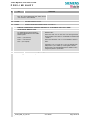
5.3.1 AT Commands for SIM Application Toolkit (GSM 11.14)
Table 5-6: AT commands for SAT
#
1
2
3
4
AT
AT^SSTA
AT^SSTN
AT^SSTGI
AT^SSTR
Command
Remote-SAT Interface Activation
Remote-SAT Notification
Remote-SAT Get Information
Remote-SAT Response
5.3.2 AT Commands originating from GSM 07.07
Table 5-7: AT commands from GSM 07.07- new
#
AT
5 AT+CCWA
6 AT+CCUG
7 AT+CMER
Command
Call waiting
Closed User Group
Mobile Equipment Event Reporting
TC35_TC35i_MIG_01_V01.01
29.1.2003
Page 32 of 34
TC35i: Migration from TC35 to TC35i
PRELIMINARY
#
AT
8 AT+CIND
Command
Indicator Control
5.3.3 Commands from change requests TC/AC/MC35
Table 5-8: AT commands from change requests
#
AT
9 AT^SRTC
Command
Select, query and test ringing tones
5.3.4 New features for TC35i only – misc.
Table 5-9: New TC35i features
#
AT
10 AT\V
11 AT^SAIC
12 AT^SMOND
13 AT^SSR
14 AT%D
15 AT+ICF
16 AT+IFC
17 AT+CMMS
Command
Configure CONNECT Response
Audio Interface Configuration
Monitoring
SIM READY
Automatic dial on DTR line activation
Set TE-TA control character framing
Set TE-TA local data flow control
More Messages to Send
5.3.5 Siemens defined AT commands for enhanced functions
Table 5-10: New Siemens defined AT commands
#
AT
18 AT^SNFA
19 AT^SLMS
20 AT^SBV
21 AT^SPBD
5.4
Command
Set or query of microphone attenuation
List Memory Storage
Battery Voltage
Delete the given Phonebook
List of unsupported AT-Commands
TC35i supports the entire TC35 AT command set.
5.5
List of AT-Commands for V.25ter compatibility
These commands return "OK" but have no functionality in both TC35i and TC35.
Table 5-11: V.254ter compatibility commands
#
1
2
3
4
5
6
7
AT
ATL
ATM
ATP
ATS2*
ATS6
ATS8
ATT
Command
Set monitor speaker loudness
Set monitor speaker mode
Select pulse dialling
Escape code sequence
Set pause before blind dialling
Set number of seconds to wait for comma dial modifier
Select tone dialling
TC35_TC35i_MIG_01_V01.01
29.1.2003
Page 33 of 34
TC35i: Migration from TC35 to TC35i
PRELIMINARY
*not "formally" listed as supported by TC35i.
TC35_TC35i_MIG_01_V01.01
29.1.2003
Page 34 of 34