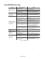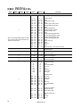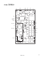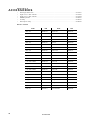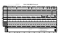
1
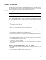
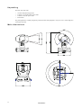
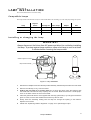
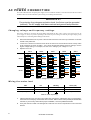
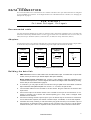
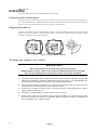
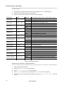
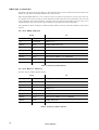
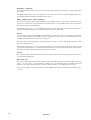
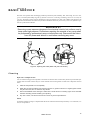
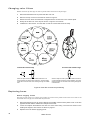
MAC 300
user manual
table of
CONTENTS
Introduction ..........................................................................................................3
Lamp Installation..................................................................................................5
AC Power Connection..........................................................................................6
Data Connection...................................................................................................7
Rigging ..................................................................................................................8
Fixture Settings ....................................................................................................9
Operation ............................................................................................................15
Basic Service ......................................................................................................17
Troubleshooting .................................................................................................21
DMX Protocol......................................................................................................22
Error Messages ..................................................................................................24
PCB Layout .........................................................................................................25
Accessories ........................................................................................................26
Specifications .....................................................................................................27
©1999 - 2000 Martin Professional A/S, Denmark.
All rights reserved. No part of this manual may be
reproduced, in any form or by any means, without
permission in writing from Martin Professional A/S,
Denmark.
Printed in Denmark.
P/N 35000075, Rev. C.
section 1
INTRODUCTION
Thank you for selecting the Martin MAC 300. The MAC 300 is an automated yoke-mounted Fresnel washlight
employing a 250 watt discharge lamp. It provides cyan, magenta, and yellow (CMY) color mixing, separate color
wheel with 6 replaceable dichroic filters, variable frost, strobe effects, full-range dimming, and accurate 16-bit movement. Efficient optics, attractive design, modular construction and numerous other features make the MAC 300 well
suited for any lighting application calling for color mixing and soft focus in a 250 watt fixture.
M AC 3 0 0 s a f e t y i n fo r m a t i o n
WARNING!
This product is for professional use only. It is not for household use.
This product presents risks of lethal or severe injury due to fire and heat, electric shock, ultraviolet radiation, lamp
explosion, and falls. Read this manual before powering or installing the fixture, follow the safety precautions listed
below and observe all warnings in this manual and printed on the fixture. If you have questions about how to operate
the fixture safely, please contact your Martin dealer or call the Martin 24-hour service hotline at +45 70 200 201.
To p r o t e c t y o u r s e l f a n d o t h e r s f r o m e l e c t r i c s h o c k
• Disconnect the fixture from AC power before removing or installing the lamp, fuses, or any part, and when not in
use.
• Always ground (earth) the fixture electrically.
• Use only a source of AC power that complies with local building and electrical codes and has both overload and
ground-fault protection.
• Do not expose the fixture to rain or moisture.
• Refer any service operation not described in this manual to a qualified technician.
To p r o t e c t y o u r s e l f a n d o t h e r s f r o m U V r a d i a t i o n a n d l a m p e x p l o s i o n
• Never operate the fixture with missing or damaged lenses and/or covers.
• When replacing the lamp, allow the fixture to cool for at least 5 minutes before opening the fixture or removing the
lamp. Protect your hands and eyes with gloves and safety glasses.
• Do not stare directly into the light. Never look at an exposed lamp while it is lit.
• Replace the lamp if it becomes defective or worn out, or before usage exceeds 125 percent of the rated average life.
To p r o t e c t y o u r s e l f a n d o t h e r s f r o m b u r n s a n d f i r e
• Never attempt to bypass the thermostatic switch or fuses. Always replace defective fuses with ones of the specified
type and rating.
• Keep all combustible materials (for example fabric, wood, paper) at least 0.4 meters (16 inches) away from the fixture. Keep flammable materials well away from the fixture.
• Do not illuminate surfaces within 0.4 meters (16 inches) of the fixture.
• Provide a minimum clearance of 0.1 meters (4 inches) around fans and air vents.
• Never place filters or other materials over the lens.
• The exterior of the fixture can reach temperatures up to 150° C (302° F). Allow the fixture to cool for at least 5 minutes before handling.
• Do not modify the fixture or install other than genuine Martin parts.
• Do not operate the fixture if the ambient temperature (Ta) exceeds 40° C (104° F).
To p r o t e c t y o u r s e l f a n d o t h e r s f r o m i n j u r y d u e t o f a l l s
• When suspending the fixture above ground level, verify that the structure can hold at least 10 times the weight of all
installed devices.
• Verify that all external covers and rigging hardware are securely fastened and use an approved means of secondary
attachment such as a safety cable.
• Block access below the work area whenever installing or removing the fixture.
Introduction
3
Unpacking
The MAC 300 comes with:
•
•
•
•
1 1/4-turn clamp mounting bracket
1 5-meter, 3-pin shielded XLR control cable
1 3-meter, 3-wire IEC power cable
1 user manual
The packing material is carefully designed to protect the fixture during shipment - always use it or a custom flight case
to transport the fixture.
Main dimensions
4
Introduction
section 2
LAMP INSTALLATION
This section describes how to install a lamp.
Compatible lamps
The lamps listed in the table below may be used with the MAC 300. Installing any other lamp may damage the fixture.
Replace
before
Average life
Color Temp.
Output
P/N
Osram HSD 250
2500 hr.
2000 hr.
6000K
68 lm/W
97010103
Philips MSD 250/2
2200 hr.
2000 hr.
6500K
72 lm/W
97010100
Philips MSD 200
2200 hr.
2000 hr.
5600K
67 lm/W
97010106
Lamp
Installing or changing the lamp
WA R N I N G !
Always disconnect the fixture from AC power and allow it to cool before installing
the lamp. To protect against lamp explosion, allow a hot lamp to cool for at least
5 minutes before removing the lamp socket.
reflector alignment screws
lamp socket assembly
Figure 1: Lamp installation
1.
Remove the 2 Phillips screws from the lamp socket assembly. Pull the lamp and socket out of the head.
2.
Remove the old lamp, if any, from the socket.
3.
Holding the new lamp by its ceramic base (do not touch the glass), align the small pin with
the small hole and insert the lamp squarely into the socket. Make sure that the 4 small projections on the base contact the face of the socket.
4.
Clean the glass bulb with the cloth supplied with the lamp, particularly if your fingers touched the
glass. A clean, lint-free cloth wetted with alcohol may also be used.
5.
Gently insert the assembly, making sure the lamp fits through the opening in the reflector.
Replace the 2 screws.
6.
Please see “Optimizing reflector alignment” on page 19 to optimize light output.
Lamp Installation
5
section 3
A C PO W E R C O N N E C T I O N
This section describes how to tap the power supply for local conditions and how to wire the mains lead. Do not connect
the MAC 300 to an electrical dimmer system: doing so can damage the electronics.
WA R N I N G !
For protection from dangerous electric shock, the fixture must be grounded
(earthed). The AC supply shall have overload and ground-fault protection.
C h a n g i n g vo l t ag e a n d f r e q u e n cy s e t t i n g s
The factory settings are printed on the serial number label under the base. These settings must match the local AC
power supply as closely as possible! Operating at the incorrect power setting can result in poor light output, greatly
reduced lamp life, overheating and/or damage to the fixture.
1.
Disconnect the fixture from AC power. Unscrew and remove the cover from top of the base on the side
closest to the power inlet.
2.
Locate the 7-terminal connection block. Move the wires to the terminals that most closely match
local conditions as shown in Table 1. If the local voltage falls halfway between settings, use the
higher voltage setting. For example, use the 120 V setting if your voltage is 110 V.
3.
Replace the cover.
100 V
50 Hz
60 Hz
0V
20 V
120 V
230 V
250 V
60 Hz
50 Hz
0V
20 V
120 V
230 V
250 V
60 Hz
50 Hz
BLUE
BROWN
BLACK
BLUE
BROWN
BLACK
120 V
BLUE
0V
20 V
120 V
230 V
250 V
60 Hz
50 Hz
BROWN
BLACK
BLUE
0V
20 V
120 V
230 V
250 V
60 Hz
50 Hz
BROWN
BLACK
210 V
0V
20 V
120 V
230 V
250 V
60 Hz
50 Hz
0V
20 V
120 V
230 V
250 V
60 Hz
50 Hz
230 V
BLUE
BROWN
BLACK
BLUE
BROWN
BLACK
0V
20 V
120 V
230 V
250 V
60 Hz
50 Hz
0V
20 V
120 V
230 V
250 V
60 Hz
50 Hz
BLUE
BROWN
BLACK
BLUE
BROWN
BLACK
250 V
0V
20 V
120 V
230 V
250 V
60 Hz
50 Hz
0V
20 V
120 V
230 V
250 V
60 Hz
50 Hz
BLUE
BROWN
BLACK
BLUE
BROWN
BLACK
Table 1: Voltage and frequency settings
Wiring the mains lead
Wire
Pin
Marking
Screw (US)
brown
live
“L”
yellow or brass
blue
neutral
“N”
silver
yellow/green
ground
green
Table 2: Cord cap wiring
6
1.
Install a grounding-type cord cap on the mains lead. Connect the yellow/green wire to ground (earth),
the brown wire to live (hot), and the blue wire to neutral. Table 2 shows some possible pin identification
schemes; if you have any doubts about proper installation, consult a qualified electrician.
2.
Verify that the feed cable is undamaged and rated for the current requirements of all connected
devices.
AC Power Connection
section 4
DATA CONNECTION
This section describes how to connect fixtures to a controller. The MAC 300’s 3-pin XLR connectors are configured
for use with DMX-512 controllers. To reconfigure them for use with Martin Protocol controllers, see “Changing the
XLR pin-out” on page 19.
XLR PIN-OUT
Pin 1: shield Pin 2: signal - Pin 3: signal +
Recommended cable
Use cable designed for RS-485 devices with low capacitance and a characteristic impedance of 85 to 150 ohms. The
cable must be electrically shielded and have at least 1 pair of twisted wires. The minimum wire size is 0.2 mm2 (24
AWG) for runs up to 300 meters (1000 ft.), and 0.322 mm2 (26 AWG) for runs up 500 meters (1640 ft.).
Adaptors
As many devices have 5-pin connectors and others have 3-pin connectors with reversed signal polarity, adaptor cables
as shown below may be required. Insert a termination plug in the output of the last fixture on the link.
5-pin to 3-pin
Adaptor
3-pin to 5-pin
Adaptor
3-pin to 3-pin
Phase-Reversing
Adaptor
Termination Plug
Male
Female
Male
Female
Male
Female
Male
1
2
3
4
5
1
2
3
1
2
3
1
2
3
4
5
1
2
3
1
2
3
1
2
3
P/N 11820005
Construct
P/N 11820006
120
P/N 91613017
Figure 2: Cable adaptors and termination
Building the data link
1.
DMX controllers: Connect a data cable to the controller’s data output. If controller has a 5-pin female
socket, use a 5-pin male to 3-pin female adaptor cable (P/N 11820005).
Martin RS-485 protocol controllers: First, connect a 3-pin “swapper” cable (P/N 11820006) to the
controller’s data output; then, connect a regular data cable to the swapper cable. Alternatively, reconfigure the XLR pin-out as described on page 19.
2.
If convenient, you may split the link into branches using a splitter such as the Martin 4-Channel
Opto-Isolated RS-485 Splitter/Amplifier. Do not use a “Y” connector to split the link.
3.
Lead the data cable from the controller to the first fixture. Plug the cable into the fixture’s data
input socket.
4.
Connect the output of the fixture closest to the controller to the input of the next fixture. If connecting to another type of fixture with reversed-polarity (pin 3 cold), insert a swapper cable
between the two fixtures.
5.
Continue connecting fixtures output to input. Up to 32 devices may be connected on a serial link.
If more fixtures are required, use another controller output, if available, or an RS-485 amplifier.
6.
Terminate the link by inserting a male termination plug (P/N 91613017) into the data output of
the last fixture. A termination plug is simply an XLR connector with a 120 ohm, 0.25 W resistor
soldered across pins 2 and 3. If a splitter is used, each branch of the link must be terminated.
Data Connection
7
section 5
RIGGING
This section briefly describes how to install the MAC 300 on a truss.
Location and orientation
The MAC 300 may be installed in any orientation. It shall be located at least 0.4 meters (16 inches) away from the surface to be illuminated and any combustible materials. The lamp socket at the back of the head reaches temperatures up
to 150° C (302° F): the fixture should not be located in publicly trafficked areas.
Rigging hardware
The MAC 300 includes a clamp mounting bracket to which 1 or 2 rigging clamps (not included) can be bolted with
locking 12 mm (1/2 in.) hardware. The clamp bracket fastens to the base with 1/4-turn fasteners. For clamps available
from Martin, see the list of accessories on page 26.
Figure 3: Clamp mounting bracket
To h a n g t h e f i x t u r e o n a t r u s s
WA R N I N G !
Block access below the work area before proceeding.
Always fasten a safety cable to the reinforced attachment point in the base.
The 1/4-turn fasteners are locked only when turned fully clockwise.
8
1.
Verify that the clamps are in good condition and can bear at least 10 times the weight of the fixture. Bolt
clamps to the bracket with a grade 8.8 (minimum) M12 bolt and lock nut, or as recommended by the
clamp manufacturer, through the 13 mm holes in the clamp mounting bracket.
2.
Align the clamp mounting bracket with any 2 key slots on the base. Insert both locking pins into
the slots and turn both levers a full 1/4 turn clockwise to lock.
3.
Verify that the structure can bear at least 10 times the weight of all installed fixtures, clamps,
cables, auxiliary equipment, etc.
4.
Working from a stable platform, clamp the fixture to the structure.
5.
Install a safety cable that can bear at least 10 times the weight of the fixture securely to the
structure and anchor the cable to the dedicated attachment point in the base. The attachment
point is designed to fit a carabiner clamp.
Rigging
section 6
FIXTURE SETTINGS
This section describes how to set the address and personalities, read lamp hours, DMX values, and other information;
calibrate effects, control the fixture manually, and run test and demo programs from the 4-digit LED control panel.
Functions that do not require feedback can also be performed remotely via the serial link using the MPBB1 Uploader.
Please refer to the MPBB1 manual.
Menu navigation
The DMX or Martin address, depending on the mode, and any error messages are displayed after the MAC 300 resets.
To enter the menu, press [MENU]. Use the [↑] and [↓] keys to move within the menu. To select a function or submenu,
press [Enter]. To escape, press [MENU].
Address/
Messages
AddR
PSET
PERS
INFO
TEST
UTIL
MAN
AdJ
DMX
MOdE
PATI
HRS
TSEQ
UPLd
RST
RST
SWAP
PINV
TINV
TOTL
RSET
DMXL
dEMO
L ON
L ON
MINP
MAXP
MINT
MAXT
GO
LOFF
LOFF
L HR
STCO
SHUT
...
E SP
SHUT
FEbA
dIM
HEAd
MART
AUTO
PTSP
dLOF
TOTL
RSET
PCb
dRES
L ST
ALON
TOTL
RSET
dISP
dINT
dMOd
VER
CYAN
FACT
MAG
ETST
MTST
STST
CPU
FEbA
dISP
SCUT
YEL
dIM
COL
CYAN
MAG
YEL
FROS
COL
PATI
FROS
CAL
PAN
EFFb
TILT
TRAC
MOdE
CAL
P OF
T OF
d OF
C OF
M OF
Y OF
dFOF
dFSE
FACT
CUS1
CUS2
CUS3
Figure 4: MAC 300 menu
Fixture Settings
9
Pe rs o n a l i t y s e t t i n g s
The MAC 300’s personality settings are shown in Table 3; they are described as well in the following section. To select
a personality setting:
1.
Press [Menu] as required to reach the main menu. Navigate to PE RS and press [Enter].
2.
Navigate to the desired setting and press [Enter].
3.
Select the desired option with the arrow keys and press [Enter].
Personality
Path
Pan/tilt swap
PATI /SW AP
Pan inverse
Options
Effect (Default setting shaded, * indicates DMX override)
ON
Map DMX pan control to tilt channel and vice versa.
OFF
Normal pan and tilt control.
ON
Reverse DMX pan control (right Æ left).
OFF
Normal pan control (left Æ right).
ON
Reverse DMX tilt control (down Æ up).
OFF
Normal tilt control (up Æ down).
FAS T
Optimize movement for speed.*
SLO W
Optimize movement for smoothness.*
ON
Enable DMX lamp off command.
OFF
Disable DMX lamp off command.*
ON
Enable DMX reset command.
OFF
Disable DMX reset command.*
ON
Lamp strikes automatically within 90 seconds of power on.
OFF
Lamp remains off until “lamp on” command is sent.
ON
Display stays on.
OFF
Display goes out 2 minutes after last key press.
10 - 100
Adjust display intensity.
NOR M
Normal dimming.
TUN G
Simulated tungsten dimming.
ON
Color and CMY wheels turn the shortest direction.*
OFF
Wheels turn same direction.*
ON
Enable feedback on color and CMY wheels.
OFF
Disable feedback on color and CMY wheels.
MOd 1
Absolute delta value algorithm (for most controllers)
MOd 2
Real delta value algorithm
1-1 0
Tracking samples. Increase if pan/tilt is not smooth.
PATI/PINV
Tilt inverse
PATI/TINV
Pan/tilt speed
PTSP
DMX lamp off
dLOF
DMX reset
dRES
Automatic lamp on
Display on/off
ALON
dISP
Display intensity
dINT
Dimmer mode
dMOd
Shortcuts
SCUT
Effects feedback
EFFb
Tracking algorithm
Tracking samples
TRAC/MOdE
TRAC/CAL
Table 3: Personality settings
Custom personality configurations
Three sets of custom personality configurations can be stored for later recall. To create and use a custom configuration:
10
1.
Set the personalities as desired.
2.
Navigate to PE RS / d FSE and press [Enter].
3.
Select CUS 1 , CU S2 , or CUS 3 and press [Enter].
4.
Select SAV E to create a custom configuration or LO Ad to recall. Press [Enter].
5.
To load the factory default personality settings, navigate to PER S / dF SE / FA CT and press
[Enter].
Fixture Settings
Adjusting the LED display
Inv er t
To flip the display vertically, press the up-arrow [↑] and down-arrow [↓] keys simultaneously.
Adjust intensity
To adjust the display intensity, set PE RS/d INT to a level between 10 and 100.
Blackout
To blackout the display 2 minutes after the last key-press, toggle PER S/d ISP to O FF.
Protocol selection
The MAC 300 can be controlled with DMX-512 and Martin RS-485 protocol controllers. When used with DMX controllers, there are 4 control protocols to choose from. The control option - DMX mode 1, 2, 3, 4; or Martin - must
match the controller setup.
1
2
3
4
5
6
7
8
9
1
2
3
4
5
6
7
8
9
10
11
1
2
3
4
5
6
7
8
9
10
11
1
2
3
4
5
6
7
8
9
10
11
12
13
shutter
dimmer
cyan
magenta
yellow
color wh.
frost
pan coarse
tilt coarse
shutter
dimmer
cyan
magenta
yellow
color wh.
frost
pan coarse
pan fine
tilt coarse
tilt fine
shutter
dimmer
cyan
magenta
yellow
color wh.
frost
pan coarse
tilt coarse
p/t speed
fx speed
shutter
dimmer
cyan
magenta
yellow
color wh.
frost
pan coarse
pan fine
tilt coarse
tilt fine
p/t speed
fx speed
DMX mode summary
Mode 1
tracking control
8-bit pan/tilt
9 channels
Mode 2
tracking control
16-bit pan/tilt
11 channels
Mode 3
tracking & vector control
8-bit pan/tilt
11 channels
Mode 4
tracking & vector control
16-bit pan/tilt
13 channels
The DMX modes are summarized above. Mode 4 provides full control; it is recommended unless channels are limited.
To s e l e c t a p r o t o c o l
Press
To
[Menu]
As required
Display main menu
[↑], [↓]
As required
Select PSE T
[Enter]
Once
Display sub menu
[↑], [↓]
As required
Select MOd E
[Enter]
Once
Display currently selected control mode
[↑], [↓]
As required
Select protocol (dM X1 , dMX 2 , dMX 3 , dMX 4 , M ART )
[Enter]
Once
Save setting. MOd E is displayed.
[Menu]
Once
Display main menu
[Menu]
Once
Display current address
Table 4: Setting a protocol
Au t o m a t i c p ro t o c o l d e t e c t i o n
Automatic protocol detection allows the MAC 300 to detect the controller type - DMX-512 or Martin RS485 - and
respond accordingly. If it is a DMX controller, the MAC 300 uses the control option selected above.
The default setting is OFF . To turn it on, navigate to the PS ET sub menu, select AUT O , press [Enter], select ON ,
and press [Enter].
Fixture Settings
11
Address selection
The address, also known as the start channel, is the first channel used to receive instructions from the controller. The
address set on the fixture must match the address set on the controller.
When selecting DMX addresses, be sure to allow the number of channels required for the protocol. If any of the control channels for one fixture overlap any of the channels for another fixture, then one of the fixtures will receive the
wrong instructions and respond incorrectly. Two MAC 300s may share the same address, however, if they are to
respond identically: they will receive the same instructions so individual control will be impossible.
Note: Whether the MAC 300 displays a DMX or Martin address at the top of the menu depends on the protocol
selected.
To s e t a D M X a d d r e s s
Press
To
[Menu]
As required
Display main menu
[↑]
As required
Select Add R
[Enter]
Once
Display address sub menu
[↑]
As required
Select DMX
[Enter]
Once
Display current DMX address
[↑], [↓]
As required
Select desired DMX address
[Enter]
Once
Save the new address. DMX is displayed.
[Menu]
Once
Display main menu
[Menu]
Once
Display current address for the P SET setting.
Table 5: Selecting a DMX address
To s e t a M a r t i n a d d r e s s
The MAC 300 uses 2 Martin RS-485 channels.
Press
To
[Menu]
As required
Display main menu
[↑]
As required
Select Add R
[Enter]
Once
Display address sub menu
[↑]
As required
Select MAR T
[Enter]
Once
Display current Martin address
[↑], [↓]
As required
Select desired Martin address
[Enter]
Once
Save the new address. MAR T is displayed.
[Menu]
Once
Display main menu
[Menu]
Once
Display current address for the P SET setting.
Table 6: Selecting a Martin address
12
Fixture Settings
Readouts
The MAC 300 has counters to track usage, maintenance intervals, lamp life, etc. One set of counters shows total
(TOT L ) accumulated usage and cannot be reset. Another set shows usage since the counter was reset (RS ET ). To
reset one of these counters, navigate to the readout and press [↑] for 5 seconds.
Hours used
To read the accumulated total number of hours the fixture has been on, navigate to INF O / H RS / T OTL and press
[Enter]. To read the number of hours since the counter was last reset, navigate to INF O / HRS / RS ET and press
[Enter]. To reset this counter, navigate to the readout and press [↑] for 5 seconds.
Lamp hours
To read the accumulated total number of lamp hours, navigate to IN FO / L H R / TO TL and press [Enter]. To read
the number of lamp hours since the counter was last reset, navigate to IN FO / L HR / R SET and press [Enter]. To
reset this counter when installing a new lamp, navigate to the readout and press [↑] for 5 seconds.
Lamp strikes
To read the accumulated total number of lamp strikes, navigate to INF O / L ST / TOT L and press [Enter]. To read
the number of lamp strikes since the counter was last reset, navigate to IN FO / L ST / RSET and press [Enter]. To
reset this counter when installing a new lamp, navigate to the readout and press [↑] for 5 seconds.
Software version
Navigate to the sub menu under INF O / VE R to read the version number of the CPU software (C PU ), feedback circuit software (F EBA ), and display module software (dIS P ).
Utilities
Upload mode
The software upload mode is engaged automatically by the MPBB1 Uploader. Engage upload mode manually only if
automatic upload fails. To do so, navigate to U TIL / U PLd and press [Enter]. Press [Enter] again when S URE is
displayed to confirm, or press [Menu] to escape. See also “Updating software” on page 19.
Demonstration program
The demonstration menu allows you to run a preprogrammed stand-alone program. Before running the demo, set the
minimum and maximum pan and tilt positions (M INP, MAXP, MIN T, MAX T ) to a good location for viewing the
effects. Select GO and press [Enter] to run the demo. Press [Menu] to stop the program.
Te s t p r o g r a m s
Te s t s e q u e n c e
Navigate to TE ST / TS EQ and press [Enter] when RU N is displayed to perform a general fixture test. Press [Menu]
to stop the program.
DMX log
The DMX log provides a quick way to check if the fixture is receiving DMX instructions correctly. The log displays
the start code (STC O ), which must be 0, and the DMX values received on each control channel.
To read a value, navigate to TES T / DMX L and press [Enter]. Scroll to an effect channel and press [Enter] to read
the DMX value received. Look up the value’s function in the DMX protocol to see if it corresponds to the effect’s
behavior.
Quality control and service tests
The PCB and F ACT menus, under TES T, contain tests for factory and service use. The factory effects test
(TES T / FA CT / ETS T ) drives all effects at 10 percent over their maximum speed.
Fixture Settings
13
Manual control
The manual control menu (MA N ) permits limited operation from the control panel.
•
•
•
•
•
•
•
•
To reset the fixture, select RST .
To turn the lamp on or off, select L O N or LoF F.
To open, close, and strobe the shutter at 3 speeds, select SHU T.
To control the dimmer, select dI M .
To move the color wheel to each position and scroll it at 3 speeds, select C OL .
To control the CMY mix, select C YAN , MAG , and YE L .
To insert the frost filter, select FR OS .
To control pan and tilt, select PA N and TIL T.
Adjustment control and calibration
The adjustment menu (A dJ ) provides the following functions:
•
•
•
•
•
•
Reset the fixture (R ST )
Turn on and off the lamp (L ON , Lo FF )
Disable pan/tilt feedback (FEb A )
Control effects in the head (H EAd )
Move the head to the home and extreme positions (PAT I )
Calibrate effects (CAL )
Head effects adjustment
The head submenu (A dJ / HEAd ) provides manual control when making mechanical adjustments, which must be
performed by a qualified technician. It allows the technician to:
•
•
•
•
Open, close, and strobe the dimmer/shutter
Move the color wheel to the open, sensor, and full color positions
Move the CMY wheels to the open, sensor, and full positions
Insert and remove the frost filter
Calibration
The calibration submenu (A dJ / CA L ) allows you to adjust the effects for uniformity between fixtures: it is not a
substitute for mechanical adjustment. To reset all calibrations to their factory defaults, select d FOF and press [Enter]
when SUR E is displayed, or press [MENU] to escape.
14
1.
Select the effect to calibrate: pan (P OF ), tilt (T O F ), dimmer/shutter (d OF ), cyan (CY OF ), magenta
(MA OF ), or yellow (YE OF ).
2.
Calibrate the effect using the arrow keys until it matches the other units. Offsets are adjustable
from 1 to 255.
3.
Press [Enter] to save the calibration.
Fixture Settings
section 7
OPERATION
This section describes the MAC 300’s controllable effects and how personality settings affect their behavior. Selecting
personalities from the control panel is described in the previous section.
Mar tin RS-485 con trol
The MAC 300 will be controllable with the Martin 3032 controller when version 2.07 of the 3032 software is released.
To respond to the controller, either Martin mode must be selected or automatic protocol detection must be enabled.
DMX-512 control
The MAC 300 may be operated with USITT DMX512 controllers in 4 different modes that mix vector and/or tracking
control with 8-bit or 16-bit pan/tilt resolution in different combinations.
Tr a c k i n g v e r s u s v e c t o r c o n t r o l
With tracking control the time it takes an effect to move from one position to another is controlled by programming a
fade time on the controller. The controller divides the move into steps and updates the fixture with small changes at the
rate required to achieve the fade. The MAC 300 follows or “tracks” the changes, and averages them with a digital filter
algorithm to ensure smooth movement at all speeds.
With vector control you set the fade speed on a separate speed channel. This provides a way to fade effects with controllers that do not have programmable fade times. With controllers that send slow or irregular tracking updates, vector
control provides smoother movement, particularly at slow speeds.
Tracking control can be enabled in vector mode by setting one or both of the speed channels to “tracking speed.” When
setting a fade speed, though, the controller fade time must be 0, i.e., the position snaps from one value to the next.
Vector control also provides a special “blackout speed” and overrides of the shortcut and pan/tilt speed personality settings.
8-bit versus 16-bit pan/tilt resolution
With 8-bit pan/tilt resolution, pan and tilt are divided into 256 equal increments. Finer position control and smoother
movement is provided in the 16-bit modes, which divide pan into 40,192 positions and tilt into 39,424 positions.
Controllable effects
All mechanical effects are reset to a home position when the fixture is powered up and they can also be reset from the
controller. The DMX Reset function (PE RS/ dRE S ), when set to off, prevents accidental resets by adding the
requirement that each CMY channel be set to a DMX value from 230 to 232.
An on-the-fly position correction system automatically corrects the position of the CMY wheels and the color wheel.
Though this feature can be disabled by turning Effects Feedback (P ERS /EFF b ) off, doing so is not recommended.
Lamp
With the default setting, the lamp remains off until a “lamp on” command is sent from the controller. Note: A peak of
electric current that can be many times the operating current is drawn for an instant when striking a discharge lamp.
Striking many lamps at once may cause a voltage drop large enough to prevent lamps from striking or draw enough
current to trip circuit breakers. If sending “lamp on” commands to multiple fixtures, program a sequence that strikes
lamps one at a time at 5 second intervals.
The MAC 300 automatically strikes the lamp within 90 seconds of being powered on only if the Automatic Lamp On
setting (P ERS /AL ON ) is turned on. A delay determined by the fixture address staggers lamp strikes to prevent
excessive current draw.
The lamp can be turned off from the controller. Note: the lamp cannot be restruck for 8 minutes after being turned off.
Accidental “lamp off” commands can be prevented by turning the DMX Lamp Off setting (PER S/d LOF ) off.
Operation
15
Dimmer / shutter
The mechanical dimmer/shutter system provides full, high-resolution dimming, and random or variable strobe effects
up to 14 Hz.
The Dimmer Mode (PER S / dMO d ) setting allows you to select between linear or simulated tungsten fade curves.
For simulated tungsten dimming, the fade time must be set to 0.
CMY subtractive color mixing
The CMY color mixing system is based on graduated cyan, magenta, and yellow color filters. A continuous range of
colors may be achieved by varying the amount of each filter from 0 to 100%. Random CMY color mixing at three
speeds can be selected on DMX channel 6.
The Shortcuts setting (PE RS/ SCU T ) determines whether or not the CMY wheels always take the shortest path to
the next position; this setting may be overridden on the speed channel in vector mode.
Color
The color wheel provides a 5500 to 2900K color temperature correction (CTC) filter, a UV filter, and 4 saturated dichroic color filters. The filters are replaceable; please see “Changing color filters” on page 18, and additional colors are
available from Martin; please see “Accessories” on page 26.
The wheel can be scrolled continuously - allowing for split color effects - or in steps, and rotated continuously in both
directions at different speeds.
The Shortcuts setting (PE RS/S CUT ) determines whether or not the wheel always takes the shortest path to the
next position; this setting may be overridden on the speed channel in vector mode. Setting the effects speed to “blackout” causes the shutter to black out the light while the wheel is moving.
Frost
The variable frost filter softens and widens the beam. The beam field angle is 18° with no frost applied and increases to
35° with the frost applied fully.
Pa n an d ti lt
The yoke pans 540° and the head tilts 265°. Movement may be optimized for speed by setting the pan/tilt speed setting
(PER S / PTSP ) to FAS T, or for smoothness by setting it to SLOW . This setting may be overridden on the speed
channel in vector mode. Setting the speed to “blackout” causes the shutter to close while the head is moving.
The pan and tilt channels can be inverted and/or swapped in DMX mode with the pan/tilt personality settings (PE RS
/ P ATI ).
16
Operation
section 8
BASIC SERVICE
The MAC 300 operates under challenging conditions presented by heat, humidity, dust, and touring. Excessive dust,
grease, and smoke fluid buildup degrades performance and causes overheating and damage that is not covered by the
warranty. The fixture requires regular maintenance to keep performing at its peak. The schedule will depend on the
application and should be discussed with your Martin distributor. Refer any service that you are not qualified to perform to a professional technician.
WARNING!
Removing covers exposes dangerous live electrical circuits, hot surfaces, and a
lamp under high pressure. Procedures requiring the removal of any cover shall
be performed by professional users or technicians only. Disconnect the fixture
from AC power and allow it to cool before removing any cover.
Figure 5: Opening the head (base and yoke not shown)
Cleaning
Optical components
Use care when cleaning optical components. The surface on dichroic filters is achieved by means of special multi-layer
coatings and even small scratches may be visible. Residues from cleaning fluids can bake onto components and ruin
them.
1.
Allow the components to cool completely.
2.
Wash dirty lenses and filters with isopropyl alcohol. A generous amount of regular glass cleaner
may also be used, but no residues may remain.
3.
Rinse with distilled water. Mixing the water with a small amount of wetting agent such as Kodak
Photoflo will help prevent streaking and spotting.
4.
Dry with a clean, soft and lint-free cloth or blow dry with compressed air.
Fans
To maintain adequate cooling it is important that the fans be cleaned of dust and dirt periodically. Use a soft brush, vacuum, or compressed air.
Basic Service
17
Changing color filters
Handle color filters by their edges as much as possible and be careful not to chip the edges.
1.
Disconnect the fixture from AC power and allow it to cool.
2.
Remove the top cover from the head as shown in Figure 5.
3.
Rotate the color wheel until the filter is aligned with the access hole in the chassis plate.
4.
Gently tilt the filter out of the clips as shown in Figure 6 and remove.
5.
Installation is the reverse. Turn the filter so that the coated side faces the lamp.
Coated side towards lamp
Uncoated side towards stage
When an object is held up to the coated side there is no
space between the object and its reflection. The back edge
of the filter cannot be seen when looking through the coated
side.
When an object is held up to the uncoated side there is
a space between the object and its reflection. The back
edge of the filter can be seen when looking through the
uncoated side.
Figure 6: Color filter removal and positioning
Replacing fuses
Po w e r s u p p ly f u s e s
The fuses for each of the 3 low-voltage power supplies are located on the printed circuit board. If one of the circuit
board LEDs does not light, one of these fuses may be blown.
18
1.
Disconnect the fixture from AC power. Remove the 2 Philips screws from the plastic cover on the arm
opposite the side with the visible motor and pull off the cover.
2.
Locate and replace the defective fuse with one of the same rating. The fuses are shown on the
PCB layout diagram; their values are listed on page 27.
3.
Replace the cover before applying power.
Basic Service
Main fuse
The main fuse holder is built in to the mains input socket. Never replace the fuse with one of a different rating!
1.
Unplug the mains cable from the input socket. Pry open the fuse holder and remove the fuse.
2.
Replace the fuse with one of the same type. The fuse rating is listed on serial number label.
3.
Close the fuse holder and replace the mains cable.
Changing the XLR pin-out
The signal polarity of the XLR connectors can be reversed,
allowing the fixture to be connected directly to those Martin
devices with reversed polarity (pin 3 -). Optionally, a phasereversing cable may be used.
PL234
PL234
PL233
PL233
Martin pin-out
1.
Disconnect the fixture from AC power. Remove the 2
Philips screws from the cover on the arm opposite
the side with the visible motor and pull off the cover.
2.
Position the jumpers on PL 233 and PL 234 for
the desired XLR pin-out as shown.
3.
Replace the cover before applying power.
DMX pin-out
(default)
Figure 7: XLR jumpers
Optimizing reflector alignment
The MAC 300 reflector is aligned at the factory. Due to differences between lamps, however, fine adjustment may
improve performance.
1.
Strike the lamp and shine the light on a flat surface.
2.
See Figure 1. Center the hot-spot (the brightest part of the beam) by turning the 3 adjustment
screws one at a time with a 3 mm Allen wrench. If there is no hot-spot, adjust the reflector until
the light is even.
3.
To reduce a hot-spot, “push” the reflector out by turning all 3 screws counterclockwise 1/4-turn at
a time until the light is evenly distributed.
4.
If the light is brighter around the edge than it is in the center, or if light output is low, the lamp is
too far back in the reflector. “Pull” the reflector in by turning the screws clockwise 1/4-turn at a
time until the light is bright and evenly distributed.
Updating software
The latest CPU control software for the MAC 300 is available from your Martin dealer and the Martin web site. This
software is uploaded to the MAC 300 using the Martin MPBB1 Uploader. The display module and feedback system
software are not updated this way.
Normal upload
Update software is uploaded using a Martin uploader such as the MPBB1. The uploader is connected to the fixture just
like a controller. Under normal conditions, software can be installed from a remote location - there is no need to set the
MAC 300 to boot mode. Please refer to the uploader manual for further instructions.
Boot mode upload
If the data is corrupted during transmission, a check-sum error (CS ER ) occurs and after 15 seconds the fixture
switches to boot mode (U PLd ) and is ready for a boot mode upload as described in the uploader manual.
If a software upload is interrupted, the fixture must be turned off for at least 10 seconds before a new upload can be
attempted. When powered on, a check-sum error occurs and the fixture goes into boot mode, ready for a second upload
attempt. Select boot mode upload on the uploader.
If there is no functional software in memory, the fixture must be set to boot mode manually. If the control panel works,
select UP Ld from the U TIL menu and confirm when S URE is displayed by pressing [ENTER].
Basic Service
19
If the control panel does not work, boot mode can be engaged by
moving jumper PL121 on the main circuit board to pins 1 and 2 as
follows.
1.
Disconnect the fixture from AC power. Remove the plastic cover from the arm opposite the side with the visible
motor.
PIN 1 È
PIN 1 È
PL121
PL121
normal setting
hard boot setting
Figure 8: Hard boot jumper
2.
Move jumper PL121 to pins 1 and 2 (hard boot setting). See also the diagram on page 25.
3.
Perform a boot-mode upload as described in the uploader manual.
4.
Disconnect the fixture from AC power. Move the hard boot jumper back to the normal setting and
replace the cover.
Changing lenses
A wide angle diffusion “lens” is available for the MAC 300. The diffuser gives the MAC 300 a 59° beam angle. If the
frost filter is fully applied, the beam angle is 67°. Photometric data for this option is available at http://www.martin.dk/
service/Photometrics/MAC300-wide.htm.
The kit may be ordered by P/N 91610016, “Wide angle diffuser lens kit for MAC 300." To change lenses:
20
1.
Disconnect the fixture from AC power. Remove the top head cover.
2.
From the outside of the bottom head cover, remove the screw that holds the lens in place.
Remove the lens.
3.
Install the new lens in the same position as the old one, in the inside lens slot.
4.
Replace the screw to secure the new lens. Replace the top head cover.
Basic Service
section 9
TR O U B L E S H O O T I N G
Problem
One or more of the
fixtures is completely
dead.
Fixtures reset correctly
but all respond
erratically or not at all to
the controller.
Fixtures reset correctly
but some respond
erratically or not at all to
the controller.
An effect fails to reset
correctly.
No light and “LERR”
error message
displayed.
Lamp cuts out
intermittently.
Probable cause(s)
Remedy
No power to fixture.
Check that power is switched on and
cables are plugged in.
Primary fuse blown.
Replace fuse.
Secondary fuse(s) blown (located
on PCB inside base).
Check fuses on PCB and replace.
The controller is not connected.
Connect controller.
XLR pin-out of the controller does
not match pin-out of the first fixture
on the link (i.e. signal is reversed).
Install a phase-reversing cable between
the controller and the first fixture on the
link.
Bad data link connection
Inspect connections and cables. Correct
poor connections. Repair or replace damaged cables.
Data link not terminated with 120Ω
termination plug.
Insert termination plug in output jack of
the last fixture on the link.
Incorrect addressing of the fixtures.
Check address and protocol settings.
One of the fixtures is defective and
disturbs data transmission on the
link.
Bypass one fixture at a time until normal
operation is regained: unplug both connectors and connect them directly
together. Have the defective fixture serviced by a qualified technician.
XLR pin-out on fixtures does not
match (pins 2 and 3 reversed).
Install a phase-reversing cable between
the fixtures or swap pins 2 and 3 in the fixture that behaves erratically.
The effect requires mechanical
adjustment.
Contact Martin technician for service.
The ballast and transformer settings do not match local AC voltage and frequency.
Disconnect fixture. Check ballast and
transformer settings and correct if necessary.
Lamp missing or blown
Disconnect fixture and replace lamp.
Fixture is too hot.
Allow fixture to cool.
Reduce ambient room temperature.
Recalibrate temperature sensors.
The ballast and transformer settings do not match local AC voltage and frequency.
Check ballast and transformer settings
and correct if necessary.
Table 7: Troubleshooting
Troubleshooting
21
appendix a
DMX PROTOCOL
DMX1
DMX2
DMX3
DMX4
Value
Percent
Function
Start code = 0
Shutter, Strobe, Reset, Lamp On/Off
0 - 19
20 - 49
50 - 72
73 - 79
80 - 99
100 - 119
120 - 127
128 - 147
148 - 167
168 - 187
188 - 190
191 - 193
194 - 196
197 - 199
200 - 202
203 - 207
208 - 217
218 - 227
228 - 237
238 - 247
248 - 255
0-7
8 - 19
20 - 28
29 - 31
31 - 39
39 - 47
47 - 50
50 - 58
58 - 65
66 - 73
74 - 75
75 - 76
76 - 77
77 - 78
78 - 79
80 - 81
82 - 85
85 - 89
89 - 93
93 - 97
97 - 100
Shutter closed
Open
Strobe, fast to slow
Open
Opening pulse, fast to slow
Closing pulse, fast to slow
Open
Random strobe, fast
Random strobe, medium
Random strobe, slow
Open
Random opening pulse, fast
Random opening pulse, slow
Random closing pulse, fast
Random closing pulse, slow
Open
Reset, see note
Open
Lamp on
Open
Lamp off: time > 5 seconds, see note
2
0 - 255
0 - 100
Dimmer
Closed to open
3
0 - 255
0 - 100
Cyan
White to full cyan
4
0 - 255
0 - 100
Magenta
White to full magenta
5
0 - 255
0 - 100
Yellow
White to full yellow
0 - 179
0
26
52
78
104
130
156
0 - 70
0
10
20
31
41
51
61
Color
Continuous scroll
White
CTC 5500-2900K
Pink 312
UV
Red 308
Green 206
Blue 108
180 - 183
184 - 187
188 - 191
192 - 195
196 - 199
200 - 203
204 - 207
71 - 72
72 - 73
74 - 75
75 - 76
77 - 78
78 - 80
80 - 81
Stepped scroll
Blue 108
Green 206
Red 308
UV
Pink 312
CTC 5500-2900K
White
208 - 226
227 - 245
82 - 88
89 - 96
Continuous rotation
CW, fast to slow
CCW, slow to fast
246 - 248
249 - 251
252 - 255
96 - 97
98 - 98
99 - 100
Random CMY color
Fast
Medium
Slow
1
Note: To override (DMX) Reset or Lamp
Off = OFF, set all 3 CMY channels to a
value from 230 to 232.
6
22
DMX Protocol
DMX1
DMX2
DMX3
DMX4
Value
Percent
Function
7
0 - 255
0 - 100
Frost
Open (off) to full
8
0 - 255
0 - 100
Pan
Left to right (128 = neutral)
-
9
-
9
0 - 255
0 - 100
Pan Fine (LSB)
Left to right (128 = neutral)
9
10
9
10
0 - 255
0 - 100
Tilt
Up to down (128 = neutral)
-
11
-
11
0 - 255
0 - 100
Tilt Fine (LSB)
Up to down (128 = neutral)
0-2
3 - 245
246 - 248
249 - 251
252 - 255
0-1
1 - 96
96 - 97
98 - 98
99 - 100
Pan/Tilt Speed
Tracking control
Vector speed, fast to slow
Tracking, PTSP SLOW (override FAST)
Tracking, PTSP FAST (override SLOW)
Blackout while moving
0-2
3 - 245
246 - 248
249 - 251
252 - 255
0-1
1 - 96
96 - 97
98 - 98
99 - 100
Effects Speed
Dimmer, CMY filters
Tracking control
Vector speed, fast to slow
Tracking, SCUT OFF (overrides ON)
Tracking, SCUT ON (overrides OFF)
Vector speed, fast
0-2
3 - 245
246 - 248
249 - 251
252 - 255
0-1
1 - 96
96 - 97
98 - 98
99 - 100
Color wheel
Tracking control
Vector speed, fast to slow
Tracking, SCUT OFF (overrides ON)
Tracking, SCUT ON (overrides OFF)
Blackout while moving
0-2
3 - 251
252 - 255
0-1
1 - 98
99 - 100
Frost
Tracking control
Vector speed, fast to slow
Vector speed, fast
-
-
-
-
10
11
12
13
DMX Protocol
23
appendix b
ERROR MESSAGES
Display readout
24
Appears if...
What to do
AUTO (Automatic protocol detection error)
... automatic protocol detection is
enabled and there is no control input.
• Verify that controller is connected
properly and sending data.
LERR (Lamp error)
... the lamp doesn’t ignite within 10
minutes of receiving the ‘Lamp ON’
command.
• Check the lamp
• Check voltage and frequency settings
MERR (Memory error)
... the EEPROM memory cannot be
read.
• Contact service technician.
CSER (Check-sum error)
...a software upload is unsuccessful.
• Reload software, see page 19.
****
... there is no communication between
the control panel and motherboard.
This appears briefly when switching on
the fixture.
• Check fuses.
• Check cable between control panel
and motherboard.
• Reinstall software.
• Contact service technician.
ShER (Short error)
... the fixture detects the lamp is ON
but no ‘Lamp ON’ command has been
received. This can occur if the lamp
relay is stuck.
• The fixture may be operated but
remote lamp on/off may be effected.
• Contact service technician.
Hot (Hot lamp)
... you attempt to strike the lamp within
8 minutes after having switched it off.
The fixture will store the ‘Lamp ON’
instruction and strike the lamp once the
8 minutes period has elapsed.
• Wait until the lamp strikes.
FbEP (Feedback error pan)
FbET (Feedback error tilt)
FbER (Feedback error pan/tilt)
...pan (FbEp), tilt (FbET) or both
(FbER) feedback circuits are malfunctioning.
• The fixture will still operate, though
with reduced maximum speed to prevent the fixture from losing track of its
position.
• Contact service technician.
PAER (Pan time-out)
TIER (Tilt time-out)
...the pan or tilt indexing circuit is malfunctioning.
• After the time-out the fixture will work
normally.
• Contact service technician.
COER (Color wheel time-out)
CYER (Cyan wheel time-out)
MAER (Magenta wheel time-out)
YEER (Yellow wheel time-out)
...the magnetic-indexing circuit malfunctions or the effect wheel is misaligned.
• After the time-out, the effect in question stops in a random position.
• Contact service technician.
Error Messages
appendix c
PCB LAYOUT
Fan
Opto1
Opto2
Display
Brown
Red
Fan
Switch
Hall sensor
Hard boot
jumper
Color
wheel
XLR jumper
Link
Cyan
Light sensor
Magenta
Yellow
Dimmer
Frost
Pan
AC input
Tilt
PCB Layout
25
appendix d
ACCESSORIES
•
•
•
•
•
•
Wide angle diffuser lens: .......................................................................................................................... 91610016
Flight case, 4 x MAC 250/300:.................................................................................................................. 91510005
Flight case, 2 x MAC 250/300:.................................................................................................................. 91510004
MPBB1 Uploader: ..................................................................................................................................... 90758410
G-clamp: ................................................................................................................................................... 91602003
Half-coupler clamp: .................................................................................................................................. 91602005
Color filters
Filter
26
P/N
Filter
P/N
Blue 101
46404301
Purple 502
46404314
Blue 102
46404326
Purple 509
46404338
Blue 103
46404327
Red 301
46404315
Blue 104
46404302
Red 304
46404339
Blue 105
46404328
Red 305
46404340
Blue 106
46404303
Red 308
46404316
Blue 107
46404325
Red 309
46404341
Blue 108
46404320
Yellow 601
46404317
Blue 111
46404304
Yellow 602
46404342
Cyan 401
46404305
Yellow 603
46404318
CTC 5500-2900K
46404306
Yellow 604
46404319
CTC 5500-3400K
46404324
Green 201
46404329
CTC 5500-4200K
46404307
Green 202
46404310
CTC 3200-5600K
46404308
Green 203
46404330
CTC 3200-4100K
46404309
Green 204
46404321
Magenta 501
46404333
Green 205
46404331
Magenta 504
46404334
Green 206
46404311
Magenta 505
46404335
Green 208
46404332
Magenta 507
46404312
Orange 302
46404322
Pink 303
46404336
Orange 306
46404323
Pink 307
46404337
1/2 Minus Green
46404343
Pink 312
46404313
UV-transmitter
46404344
Accessories
appendix e
SPECIFICATIONS
Physical
•
•
•
•
Length........................................................................................................................................... 330 mm (13.0 in.)
Width ............................................................................................................................................ 384 mm (15.1 in.)
Maximum height (full tilt)............................................................................................................ 536 mm (21.1 in.)
Approximate weight ........................................................................................................................... 21 kg (46 lbs)
Compatible lamps
•
•
•
Osram HSD 250...................................................................................................2000 hr., 6000K, 250 W, 68 lm/W
Philips MSD 250/2 ..............................................................................................2000 hr., 6500K, 250 W, 68 lm/W
Philips MSD 200 .................................................................................................2000 hr., 5600K, 200 W, 66 lm/W
Pe rfor m an c e
•
Light output (MSD 250/2, no effects applied).......................................................................................4765 lumens
Thermal
•
Maximum ambient temperature (Ta) ................................................................................................. 40° C (104° F)
•
•
Maximum lamp-socket temperature ............................................................................................... 150° C (302° F)
Maximum shell surface temperature ................................................................................................ 90° C (194° F)
Co ntro l a nd p ro gr a m mi ng
•
•
•
•
Data pin-out ............................................................................................... pin 1 shield, pin 2 cold (-), pin 3 hot (+)
Receiver .................................................................................................................................. Opto-isolated RS-485
Protocols ................................................................................................. USITT DMX-512 (1990), Martin RS-485
DMX Channels .................................................................................................................................................9 - 13
Connections
•
•
•
AC input............................................................................................................................ 3-prong IEC male socket
Data input ................................................................................................................locking 3-pin XLR male socket
Data output ...........................................................................................................locking 3-pin XLR female socket
Fuses
•
•
•
•
Fuse 01 (primary) .............................................................................................................. 6.3 A / 250 V time-delay
Fuse F601 ......................................................................................................................... 5.0 A / 250 V time-delay
Fuse F602 .......................................................................................................................... 4.0 A / 250 V time-delay
Fuse F603 ...................................................................................................................... 0.315 A / 250 V time-delay
Design standards
•
•
•
•
Canadian safety.......................................................................................................................... CSA C22.2 NO 166
EU EMC .........................................................................................................................EN 50 081-1, EN 50 082-1
EU safety .....................................................................................................................EN 60598-1, EN 60598-2-17
US safety........................................................................................................................................... ANSI/UL 1573
Installation
•
•
•
•
Orientation ........................................................................................................................................................... any
Minimum distance to combustible materials...................................................................................... 0.4 m (16 in.)
Minimum distance to illuminated surfaces......................................................................................... 0.4 m (16 in.)
Minimum clearance around fans and air vents ...................................................................................... 0.1 m (4 in.)
Specifications
27
MAC 300 DMX Protocol
Start code = 0
Implemented from CPU software version 0.1
M ODE
1 2 3 4
25
50
75
S HUTTER
L
1
I
G
H
T
2
closed
100
125
150
O PEN
S TROBE
200
R ANDOM S TROBE
←
open
175
fast
med
225
O PEN
250
R ESET O PEN L AMP O PEN L AMP
O FF *
ON
*
> 5 sec.
slow
D IMMER
closed
10
20
30
40
open
50
60
70
80
90
3
0%
C YAN
*
100%
C
4
0%
M AGENTA
*
100%
O
L
O
R
5
0%
YELLOW
*
100%
C ONTINUOUS C OLOR S CROLL
6
(26) CTC
(0) white
(52) pink
25
B
7
M
(78) UV
50
(104) red
75
(130) green
100
20
30
40
200
225
250
60
70
80
90
P AN
240°
210°
180°
150°
120°
90°
60°
30°
right
0°
30°
60°
90°
120°
150°
180°
210°
240°
P AN F INE (LSB)
right
TILT
120°
110°
100°
90°
80°
70°
60°
50°
40°
30°
20°
10°
0°
down
10°
20°
30°
40°
50°
60°
70°
80°
90°
100°
110°
120°
TILT F INE (LSB)
11 up
25
50
75
100
125
S
175
200
225
250
slow
* Set CMY from 230 to 232 to override disabled function.
T = tracking mode (0-2 & 246-251)
S = normal PTSP or shortcuts off (246-248)
F = fast PTSP or shortcuts on (249 -251)
«·» = blackout speed (252-255)
← = variable speed, points to fast
E FFECTS S PEED
dimmer, CMY
←
T
color wheel
←
T
frost
←
11 13 T
10
20
30
40
50
130°
down
150
P AN /T ILT S PEED
10 12 T fast
P
E
E
D
175
full
50
left
- 11 -
150
F ROST
10
P - 9 - 9 left
/
T
up
9 10 9 10 130°
(156) blue
125
off
8
S TEPPED S CROLL C ONTINUOUS R OTATION R ND .
CMY
cw ←
ccw →
B G R UV PK CT W
f m s
60
70
80
90
TS TF «·»
TS TF
f
TS TF «·»
f