1
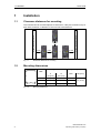
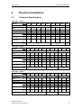
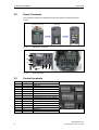
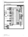
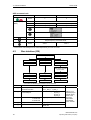
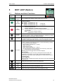
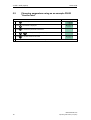
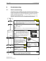
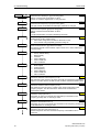
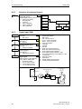
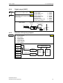
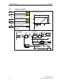
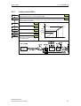
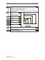
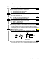
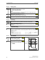
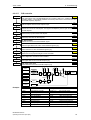
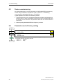
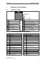
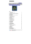
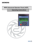
s
MICROMASTER 420
0.12 kW - 11 kW
Operating Instructions (Compact)
User Documentation
Issue 10/06
Warnings, Cautions and Notes
Issue 10/06
Warnings, Cautions and Notes
The following Warnings, Cautions and Notes are provided for your safety and as a
means of preventing damage to the product or components in the machines
connected.
Specific Warnings, Cautions and Notes that apply to particular activities are
listed at the beginning of the relevant chapters and are repeated or supplemented
at critical points throughout these chapters.
Please read the information carefully, since it is provided for your personal safety
and will also help prolong the service life of your MICROMASTER 420 Inverter and
the equipment you connect to it.
!
WARNING
¾ This equipment contains dangerous voltages and controls potentially
dangerous rotating mechanical parts. Non-compliance with Warnings or failure
to follow the instructions contained in this manual can result in loss of life,
severe personal injury or serious damage to property.
¾ Only suitable qualified personnel should work on this equipment, and only after
becoming familiar with all safety notices, installation, operation and
maintenance procedures contained in this manual. The successful and safe
operation of this equipment is dependent upon its proper handling, installation,
operation and maintenance.
¾ The DC link of all MICROMASTER modules remains at a hazardous voltage
level for 5 minutes after all voltages have been disconnected. Therefore always
wait for 5 minutes after disconnecting the inverter from the power supply before
carrying out work on any modules. The drive unit discharges itself during this
time.
¾ This equipment is capable of providing internal motor overload protection in
accordance with UL508C section 42. Refer to P0610 (level 3) and P0335.
Motor overload protection can also be provided using an external PTC via a
digital input.
¾ This equipment is suitable for use in a circuit capable of delivering not more
than 10,000 symmetrical amperes (rms), for a maximum voltage of 230/460 V
when protected by an H or K type fuse, a circuit breaker or self-protected
combination motor controller controller (for more details see Operating
Instructions Appendix F).
¾ Use Class 1 60/75 °C copper wire only with the cross-sections as specified in
the Operating Instructions..
¾ The mains input, DC and motor terminals carry dangerous voltages even if the
inverter is inoperative, wait 5 minutes to allow the unit to discharge after
switching off before carrying out any installation work.
NOTES
¾ Before installing and commissioning, please read these safety instructions and
warnings carefully and all the warning labels attached to the equipment.
¾ Make sure that the warning labels are kept in a legible condition and replace
missing or damaged labels.
¾ Maximum permissible surrounding ambient temperature is 50°C.
2
MICROMASTER 420
Operating Instructions (Compact)
Issue 10/06
Contents
Contents
1
Installation ............................................................................................................... 4
1.1
Clearance distances for mounting ............................................................................ 4
1.2
Mounting dimensions ................................................................................................ 4
2
Electrical Installation.............................................................................................. 5
2.1
Technical Specifications ........................................................................................... 5
2.2
Power Terminals ....................................................................................................... 6
2.3
Control terminals....................................................................................................... 6
2.4
Block diagram ........................................................................................................... 7
3
Factory setting ........................................................................................................ 8
3.1
50/60 Hz DIP switch.................................................................................................. 8
4
Communications..................................................................................................... 9
4.1
Establishing communications MICROMASTER 420 ⇔ STARTER.......................... 9
4.2
Establishing communications between the MICROMASTER 420 ⇔ AOP .............. 9
4.3
Bus interface (CB)................................................................................................... 10
5
BOP / AOP (Option) .............................................................................................. 11
5.1
Buttons and their Functions .................................................................................... 11
5.2
Changing parameters using as an example P0003 "Access level"........................ 12
6
Commissioning ..................................................................................................... 13
6.1
Quick commissioning .............................................................................................. 13
6.2
6.2.1
6.2.2
6.2.3
6.2.4
6.2.5
6.2.6
6.2.7
6.2.8
6.2.9
6.2.10
6.2.11
6.2.12
6.2.13
6.2.14
6.2.15
Commissioning the application ............................................................................... 15
Serial Interface (USS) ............................................................................................. 15
Selection of command source ................................................................................ 16
Digital input (DIN).................................................................................................... 16
Digital output (DOUT) ............................................................................................. 17
Selection of frequency setpoint............................................................................... 17
Analog input (ADC) ................................................................................................. 18
Analog output (DAC)............................................................................................... 19
Motor potentiometer (MOP) .................................................................................... 20
Fixed frequency (FF)............................................................................................... 20
JOG......................................................................................................................... 21
Ramp-function generator (HLG) ............................................................................. 21
Reference/limit frequencies .................................................................................... 22
Motor control (V/f) ................................................................................................... 22
Inverter/motor protection......................................................................................... 24
Inverter-specific Functions...................................................................................... 25
6.3
Series commissioning ............................................................................................. 28
6.4
Parameter reset of factory setting........................................................................... 28
7
Displays and messages ....................................................................................... 29
7.1
LED status display .................................................................................................. 29
7.2
Fault messages and Alarm messages.................................................................... 29
MICROMASTER 420
Operating Instructions (Compact)
3
1 Installation
Issue 10/06
1
Installation
1.1
Clearance distances for mounting
Fig. 1-1
1.2
100 mm
15 mm
0 mm
15 mm
Clearance distances for mounting
Mounting dimensions
Frame
Size
W
Fig. 1-2
Drilling Dimensions
Tightening Torque
H
mm (Inch)
W
mm (Inch)
Bolts
A
160 (6.30)
–
2xM4
B
174 (6.85)
138 (5.43)
4xM4
C
204 (8.03)
174 (6.85)
4xM4
H
4
...
Side of cabinet enclosure
Side of cabinet enclosure
The inverters can be mounted adjacent to each other. If they are mounted on top of
each other, however, a clearance of 100 mm has to be observed.
Nm (lbf.in)
2.5 (22.12)
Mounting dimensions
MICROMASTER 420
Operating Instructions (Compact)
Issue 10/06
2 Electrical Installation
2
Electrical Installation
2.1
Technical Specifications
1 AC 200 V – 240 V
Order No.
6SE6420-
2AB
2UC
112AA1
125AA1
kW
hp
A
A
A
3NA
2
mm
AWG
2
mm
AWG
Nm
(lbf.in)
0.12
0.16
1.8
0.9
10
3803
1.0-2.5
17-13
1.0-2.5
17-13
0.25
0.33
3.2
1.7
10
3803
1.0-2.5
17-13
1.0-2.5
17-13
Frame Size
Inverter Output
Rating
Input Current
Output Current
Recommended
Fuse
Input Cable
Output Cable
Tightening Torque
137AA1
A
0.37
0.5
4.6
2.3
10
3803
1.0-2.5
17-13
1.0-2.5
17-13
1.1
(10)
155AA1
175AA1
211BA1
215BA1
0.55
0.75
6.2
3.0
10
3803
1.0-2.5
17-13
1.0-2.5
17-13
0.75
1.0
8.2
3.9
16
3805
1.0-2.5
17-13
1.0-2.5
17-13
1.1
1.5
11.0
5.5
20
3807
2.5-6.0
13-9
1.0-6.0
17-9
B
1.5
2.0
14.4
7.4
20
3807
2.5-6.0
13-9
1.0-6.0
17-9
1.5
(13.3)
222BA1
2.2
3.0
20.2
10.4
32
3812
4.0-6.0
11-9
1.0-6.0
17-9
230CA1
C
3.0
4.0
35.5
13.6
40
3817
6.0-10
9-7
1.5-10
15-7
2.25
(20)
3 AC 200 V – 240 V
Order No.
6SE6420-
2AC
2UC
Frame Size
A
kW
0.12
0.25
0.37
0.55
hp
0.16
0.33
0.5
0.75
A
1.1
1.9
2.7
3.6
A
0.9
1.7
2.3
3.0
A
10
10
10
10
3NA
3803 3803 3803 3803
2
mm
1.0-2.5 1.0-2.5 1.0-2.5 1.0-2.5
AWG 17-13 17-13 17-13 17-13
2
mm
1.0-2.5 1.0-2.5 1.0-2.5 1.0-2.5
AWG 17-13 17-13 17-13 17-13
Nm
1.1
(lbf.in)
(10)
Inverter Output
Rating
Input Current
Output Current
Recommended
Fuse
Input Cable
Output Cable
Tightening Torque
112AA1
125AA1
137AA1
155AA1
175AA1
211BA1
215BA1
222BA1
230CA1
240CA1
255CA1
B
C
0.75
1.1
1.5
2.2
3.0
4.0
5.5
1.0
1.5
2.0
3.0
4.0
5.0
7.5
4.7
6.4
8.3
11.7
15.6
19.7
26.3
3.9
5.5
7.4
10.4
13.6
17.5
22.0
10
16
16
20
25
32
35
3803 3805 3805 3807 3810 3812 3814
1.0-2.5 1.0-6.0 1.0-6.0 1.0-6.0 2.5-10 2.5-10 4.0-10
17-13 17-9
17-9
17-9
13-7
13-7
11-7
1.0-2.5 1.0-6.0 1.0-6.0 1.0-6.0 1.5-10 2.5-10 4.0-10
17-13 17-9
17-9
17-9
15-7
13-7
11-7
1.5
2.25
(13.3)
(20)
3 AC 380 V – 480 V
Order No.
6SE6420-
2AD
2UD
Frame Size
A
kW
0.37
0.55
0.75
1.1
hp
0.5
0.75
1.0
1.5
A
2.2
2.8
3.7
4.9
A
1.2
1.6
2.1
3.0
A
10
10
10
10
3NA
3803 3803 3803 3803
2
mm
1.0-2.5 1.0-2.5 1.0-2.5 1.0-2.5
AWG 17-13 17-13 17-13 17-13
2
mm
1.0-2.5 1.0-2.5 1.0-2.5 1.0-2.5
AWG 17-13 17-13 17-13 17-13
Nm
1.1
(lbf.in)
(10)
Inverter Output
Rating
Input Current
Output Current
Recommended
Fuse
Input Cable
Output Cable
Tightening Torque
137AA1
MICROMASTER 420
Operating Instructions (Compact)
155AA1
175AA1
211AA1
215AA1
222BA1
230BA1
240BA1
255CA1
275CA1
311CA1
B
C
1.5
2.2
3.0
4.0
5.5
7.5
11.0
2.0
3.0
4.0
5.0
7.5
10.0
15.0
5.9
8.8
11.1
13.6
17.3
23.1
33.8
26.0
4.0
5.9
7.7
10.2
13.2
19.0
10
16
16
20
20
25
35
3803 3805 3805 3807 3807 3810 3814
1.0-2.5 1.0-6.0 1.0-6.0 1.5-6.0 2.5-10 4.0-10 6.0-10
17-13 17-9
17-9
15-9
13-7
11-7
9-7
1.0-2.5 1.0-6.0 1.0-6.0 1.0-6.0 1.5-10 2.5-10 4.0-10
17-13 17-9
17-9
17-9
15-7
13-7
11-7
1.5
2.25
(13.3)
(20)
5
2 Electrical Installation
2.2
Issue 10/06
Power Terminals
You can gain access to the mains and motor terminals by removing the front
covers.
SDP (BOP/AOP)
release and remove
Fig. 2-1
Push the terminal
cover down
Removing Front Covers
L3
L2/N
L1/L
U
Fig. 2-2
2.3
V
W
Power Terminals
Control terminals
Terminal
Designation
Function
1
2
3
4
5
6
7
8
9
10
11
12
13
14
15
ADC+
ADCDIN1
DIN2
DIN3
RL1-B
RL1-C
DAC+
DACP+
N-
Output +10 V
Output 0 V
Analog input (+)
Analog input (-)
Digital input 1
Digital input 2
Digital input 3
Isolated output +24 V / max. 100 mA
Isolated output 0 V / max. 100 mA
Digital output / NO contact
Digital output / Changeover contact
Analog output (+)
Analog output (-)
RS485 port
RS485 port
6
MICROMASTER 420
Operating Instructions (Compact)
Issue 10/06
2.4
2 Electrical Installation
Block diagram
PE
1/3 AC 200 - 240 V
3 AC 380 - 480 V
SI
L/L1, N/L2
or
L/L1, N/L2, L3
or
L1, L2, L3
PE
+10 V
1
0V
2
ADC+
≥ 4.7 kΩ
3
BOP link
A/D
ADC-
4
RS232
External 24 V
150.00
Hz
I
DIN1
0
DIN1
5
5
6
6
DIN2
Fn
Jog
P
BOP/AOP
DIN2
DIN3
~
DIN3
+
_
24 V
8
Output +24 V
max. 100 mA
(isolated)
9
Output 0 V
max. 100 mA
(isolated)
PNP
or
NPN
9
30 V DC / 5 A (resistive)
250 V AC / 2 A (inductive)
DC+
DC−
CPU
RL1-B
Relay
10RL1-C
11
=
DAC+
12
0 - 20 mA
max. 500 Ω
D/A
DAC-
3~
13
14
The analog input circuit can be
alternatively configured to
provide an additional digital
input (DIN4):
2
60 Hz
Not
used
P+
DIN4
DC-link connection
=
7
7
RS485
COM link
N-
2
DIP switch
15
3
50 Hz
1
PE
CB
Option
U,V,W
automatic
M
4
+
-
9
24 V
Fig. 2-3
Inverter block diagram
MICROMASTER 420
Operating Instructions (Compact)
7
3 Factory setting
3
Issue 10/06
Factory setting
The MICROMASTER 420 frequency inverter is set in the factory so that it can be
operated without any additional parameterization. To do this, the motor parameters
set in the factory (P0304, P0305, P0307, P0310), that correspond to a 4-pole 1LA7
Siemens motor, must match the rated data of the connected motor (refer to the
rating plate).
Further factory setting:
¾ Command sources P0700 = 2 (Digital input, see Fig. 3-1)
¾ Setpoint source
P1000 = 2 (Analog input, see Fig. 3-1)
¾ Motor cooling
P0335 = 0
¾ Motor current limit
P0640 = 150 %
I/O
¾ Min. frequency
Ack
P1080 = 0 Hz
Digital Inputs
¾ Max. frequency
P1082 = 50 Hz
Analog input
¾ Ramp-up time
P1120 = 10 s
¾ Ramp-down time
< 4.7 k Ω
P1121 = 10 s
Fig. 3-1
Analog and Digital Inputs
¾ Control mode
P1300 = 0
Input/Output
Terminals
Parameter
Digital input 1
Digital input 2
Digital input 3
Digital input
5
6
7
8
3/4
1/2
10/11
12/13
P0701 = 1
P0702 = 12
P0703 = 9
P1000 = 2
P0731 = 52.3
P0771 = 21
Analog input
Output relay
Analog output
3.1
ON / OFF1
(I/O)
Reverse
( )
Fault reset
(Ack)
Power supply Digital input
Frequency setpoint
Power supply Analog input
Default identification
Output frequency
50/60 Hz DIP switch
The default motor base frequency
of the MICROMASTER inverter is
50 Hz. For motors, which are
designed for a base frequency of
60 Hz, the inverters can be set to
this frequency via a DIP switch.
¾ Off position:
European defaults
(50 Hz, kW etc.)
¾ On position:
North American defaults
(60 Hz, hp etc.)
8
Function
60 Hz
50 Hz
50/60 Hz DIP switch
for frequency setting
MICROMASTER 420
Operating Instructions (Compact)
Issue 10/06
4 Communications
4
Communications
4.1
Establishing communications
MICROMASTER 420 ⇔ STARTER
The following optional components are additionally required in order to establish
communications between STARTER and MICROMASTER 420:
¾ PC <-> frequency inverter connecting set
¾ BOP if the USS standard values (refer to Section 6.2.1 "Serial Interface
(USS)") are changed in the MICROMASTER 420 frequency inverter
PC <-> frequency inverter
connecting set
MICROMASTER 420
USS settings, refer to Section 6.2.1 "Serial
Interface (USS)"
STARTER
Menu, Options --> Set PG/PC interface -->
Select "PC COM-Port (USS)" --> Properties -> Interface "COM1", select a baud rate
NOTE
The USS parameter settings in the
MICROMASTER 420 frequency inverter and
the settings in STARTER must match!
4.2
Establishing communications between the
MICROMASTER 420 ⇔ AOP
¾ Communications between AOP and MM420 are based on the USS protocol,
analog to STARTER and MM420.
¾ Contrary to the BOP, the appropriate communication parameters - both for the
MM420 as well as for AOP - should be set if the automatic interface detection
was not carried-out (refer to Table 4-1).
¾ Using the optional components, the AOP can be connected to the
communication interfaces (refer to Table 4-1).
Table 4-1
MM420 parameters
- baud rate
- bus address
AOP parameters
- baud rate
- bus address
Options
- direct connection
- indirect connection
MICROMASTER 420
Operating Instructions (Compact)
AOP at the BOP link
AOP at the COM link
P2010[1]
–
P2010[0]
P2011
P8553
–
P8553
P8552
No option necessary
BOP/AOP door mounting kit
(6SE6400-0PM00-0AA0)
Not possible
AOP door mounting kit
(6SE6400-0MD00-0AA0)
9
4 Communications
Issue 10/06
AOP as control unit
Parameter / Terminal
Command source
AOP on BOP link
AOP on COM link
4
5
P0700
/
P1000
P1035
P1036
Frequency setpoint
(MOP)
1
2032.13 (2032.D)
2032.14 (2032.E)
2036.13 (2036.D)
2036.14 (2036.E)
Output frequency of the MOP higher
Output frequency of the MOP lower
Acknowledge fault
P2104
2032.7
2036.7
* A fault can be acknowledged via the AOP independently of P0700 or P1000.
4.3
Bus interface (CB)
Bus interface (CB)
DeviceNet
CANopen
PROFIBUS
P0918
P0918
P0918 *)
Baud rate is
automatically specified
by the master
P2040
P2040
P2040
P2041
P2041
P2041
P2051
P2051
P2051
*) DIP switch for addressing the hardware must be observed
P2041[0]
P2041[1]
DeviceNet
CANopen
PZD length
Status/actual value
PZD length
control/setpoint
Data transfer type
from T_PD0_1, T_PD0_5
Data transfer type T_PD0_6
R_PD0_1
R_PD0_5
R_PD0_6
Mapping CANopen <--> MM4
P2041[2]
Baud rate
P2041[3]
P2041[4]
Diagnostics
_
10
0: 125 kbaud
1: 250 kbaud
2: 500 kbaud
PROFIBUS
Mapping CANopen <--> MM4
- response to communication errors
- baud rate
Setting is not
required (only in
special cases).
Refer to the
Operating
Instructions
"PROFIBUS
option module"
MICROMASTER 420
Operating Instructions (Compact)
Issue 10/06
5 BOP / AOP (Option)
5
BOP / AOP (Option)
5.1
Buttons and their Functions
Panel/
Button
Function
Effects
Indicates
Status
The LCD displays the settings currently used by the converter.
Start
converter
Pressing the button starts the converter. This button is disabled by default.
Activate the button:
BOP: P0700 = 1 or P0719 = 10 ... 16
AOP: P0700 = 4 or P0719 = 40 ... 46
on BOP link
P0700 = 5 or P0719 = 50 ... 56
on COM link
OFF1
+
Pressing the button causes the motor to come to a standstill at the
selected ramp down rate.
Activate the button: see button "Start converter"
Pressing the button twice (or once long) causes the motor to coast
to a standstill.
BOP: This function is always enabled
(independent of P0700 or P0719).
Stop
converter
OFF2
Change
direction
Press this button to change the direction of rotation of the motor. Reverse is
indicated by a minus (-) sign or a flashing decimal point. Disabled by default.
Activate the button: see button "Start converter".
Jog motor
In the "Ready to power-on" state, when this key is pressed, the motor starts
and rotates with the pre-set jog frequency. The motor stops when the button
is released. Pressing this button when the motor is running has no effect.
Functions
This button can be used to view additional information.
It works by pressing and holding the button. It shows the following, starting
from any parameter during operation:
1. DC link voltage (indicated by d – units V).
2. output current. (A)
3. output frequency (Hz)
4. output voltage (indicated by o – units V).
5. The value selected in P0005 (If P0005 is set to show any of the above
(1 - 4) then this will not be shown again).
Additional presses will toggle around the above displays.
Jump Function
From any parameter (rxxxx or Pxxxx) a short press of the Fn button will
immediately jump to r0000, you can then change another parameter, if
required. Upon returning to r0000, pressing the Fn button will return you to
your starting point.
Acknowledgement
If alarm and fault messages are present, then these can be acknowledged by
pressing key Fn.
Access
parameters
Increase
value
Decrease
value
Pressing this button increases the displayed value.
AOP menu
Calls the AOP menu prompting (this is only available for AOP).
Pressing this button allows access to the parameters.
Pressing this button decreases the displayed value.
MICROMASTER 420
Operating Instructions (Compact)
11
5 BOP / AOP (Option)
5.2
Issue 10/06
Changing parameters using as an example P0003
"Access level"
Step
Result on display
1
Press
to access parameters
2
Press
until P0003 is displayed
3
Press
to access the parameter value level
4
Press
or
5
Press
to confirm and store the value
6
Now access level 3 is set and all level 1 to level 3 parameters are visible to the user.
12
to the required value (example: 3)
MICROMASTER 420
Operating Instructions (Compact)
Issue 10/06
6 Commissioning
6
Commissioning
6.1
Quick commissioning
The frequency inverter is adapted to the motor using the quick commissioning
function and important technological parameters are set. The quick commissioning
shouldn't be carried-out if the rated motor data saved in the frequency inverter
(4-pole 1LA Siemens motor, star circuit configuration frequency inverter (FU)specific) match the rating plate data.
Parameters, designated with a * offer more setting possibilities than are actually
listed here. Refer to the parameter list for additional setting possibilities.
START
Factory setting
1
P0003 = 2
User access level *
1 Standard: Allows access into most frequently used parameters
2 Extended: Allows extended access e.g. to inverter I/O functions
3 Expert (For expert use only)
P0010 = 1
0
Commissioning parameter *
0 Ready
1 Quick commissioning
30 Factory setting
NOTE
P0010 should be set to 1 in order to parameterize the data of the motor rating
plate.
P0100 =...
P0100 = 1, 2
P0100 = 0
0
Europe/ North America
(enters the line supply frequency)
0 Europe [kW], frequency default 50 Hz
1 North America [hp], frequency default 60 Hz
2 North America [kW], frequency default 60 Hz
NOTE
For P0100 = 0 or 1, the setting of switch DIP2(2)
determines the value of P0100 (refer to the
parameter list).
FU-spec.
P0304 =... P0304 =... Rated motor voltage
(Nominal motor voltage [V] from rating
plate)
The rated motor voltage on the rating
plate must be checked, regarding the
star/delta circuit configuration to ensure
that it matches with the circuit
connection configured at the motor
terminal board
60 Hz
50 Hz
50/60 Hz DIP switch
for frequency setting
P0310 P0304
FU-spec.
P0305 =... P0305 =... Rated motor current
(Nominal motor current [A] from rating
plate)
FU-spec.
P0307 =... P0307 =... Rated motor power
(Nominal motor power [kW/hp] from
rating plate)
If P0100 = 0 or 2, value will be in kW. If
P0100 = 1, value will be in in hp.
P0308 =...
P0307 P0305
P0308 P0311
P0308 =... Rated motor cosPhi
(Nominal motor power factor (cos ϕ) from rating plate)
If the setting is 0, the value is automatically calculated
P0100 = 1,2: P0308 no significance, no entry required.
MICROMASTER 420
Operating Instructions (Compact)
FU-spec.
13
6 Commissioning
Issue 10/06
P0309 =... P0309 =... Rated motor efficiency
(Nominal motor efficiency in [%] from rating plate)
Setting 0 causes internal calculation of value.
P0100 = 0: P0309 no significance, no entry required.
14
FU-spec.
P0310 =...
Rated motor frequency
(Nominal motor frequency in [Hz] from rating plate)
Pole pair number recalculated automatically if parameter is changed.
50.00 Hz
P0311 =...
Rated motor speed
(Nominal motor speed in [rpm] from rating plate)
Setting 0 causes internal calculation of value.
NOTE
For slip compensation, the input is absolutely necessary.
FU-spec.
P0335 =...
Motor cooling
(Selects motor cooling system used)
0 Self-cooled: Using shaft mounted fan attached to motor
1 Force-cooled: Using separately powered cooling fan
P0640 =...
150 %
Motor overload factor
(Motor overload factor in [%] relative to P0305)
This defines the limit of the maximum output current as a % of the rated motor
current (P0305).
P0700 =...
Selection of command source
0 Factory default setting
1 BOP (keypad)
2 Terminal
4 USS on BOP link
5 USS on COM link
6 CB on COM link
2
P1000 =...
Selection of frequency setpoint
1 MOP setpoint
2 Analog setpoint
3 Fixed frequency
4 USS on BOP link
5 USS on COM link
6 CB on COM link
2
P1080 =...
0.00 Hz
Min. frequency
(enters the minimum motor frequency in Hz)
Sets minimum motor frequency at which motor will run irrespective of frequency
setpoint. The value set here is valid for both clockwise and anticlockwise rotation.
P1082 =...
50.00 Hz
Max. frequency
(enters the maximum motor frequency in Hz)
Sets maximum motor frequency at which motor will run irrespective of the
frequency setpoint. The value set here is valid for both clockwise and
anticlockwise rotation.
P1120 =...
Ramp-up time
(enters the ramp-up time in s)
Time taken for motor to accelerate from standstill up to maximum motor
frequency (P1082) when no rounding is used.
P1121 =...
10.00 s
Ramp-down time
(enters the deceleration time in s)
Time taken for motor to decelerate from maximum motor frequency (P1082) down
to standstill when no rounding is used
P1135 =...
OFF3 ramp-down time
(enters the fast stop ramp-down time in s)
Defines ramp-down time from maximum frequency to standstill for OFF3
command.
0
10.00 s
5.00 s
MICROMASTER 420
Operating Instructions (Compact)
Issue 10/06
6 Commissioning
P1300 =...
Control mode
(enters the required control mode)
0 V/f with linear characteristic
1 V/f with FCC
2 V/f with parabolic characteristic
3 V/f with programmable characteristic
0
P3900 = 1
End of quick commissioning
(start of the motor calculation)
0 No quick commissioning (no motor calculations)
1 Start quick commissioning with factory reset
2 Start quick commissioning
3 Start quick commissioning only for motor data
NOTE
For P3900 = 1,2,3 → P0340 is internally set to 1 and the appropriate data
calculated (refer to the parameter list P0340).
0
ENDE
6.2
End of quick commissioning/ drive setting
If additional functions must be implemented at the drive inverter, use the following
Section "Commissioning the application". We recommend this procedure for
drives with a high dynamic response.
Commissioning the application
An application is commissioned to adapt/optimize the frequency inverter - motor
combination to the particular application. The frequency inverter offers numerous
functions - but not all of these are required for the particular application. These
functions can be skipped when commissioning the application. A large proportion
of the possible functions are described here; refer to the parameter list for
additional functions.
Parameters, designated with a * offer more setting possibilities than are actually
listed here. Refer to the parameter list for additional setting possibilities.
START
Factory setting
P0003 = 3
6.2.1
User access level *
1 Standard (Allows access into most frequently used parameters)
2 Extended (Allows extended access e.g. to inverter I/O functions)
3 Expert (for expert use only)
1
Serial Interface (USS)
P2010 =...
USS baud rate
Sets baud rate for USS communication.
6
P2011 =...
USS address
Sets unique address for inverter.
0
P2012 =...
2
USS PZD length
Defines the number of 16-bit words in PZD part of USS telegram.
P2013 =...
127
USS PKW length
Defines the number of 16-bit words in PKW part of USS telegram.
MICROMASTER 420
Operating Instructions (Compact)
Possible
Settings:
3 1200 baud
4 2400 baud
5 4800 baud
6 9600 baud
7 19200 baud
8 38400 baud
9 57600 baud
15
6 Commissioning
6.2.2
P0700 =...
Issue 10/06
Selection of command source
2
Selection of
command source
Selects digital command source.
0 Factory fault setting
1 BOP (keypad)
2 Terminal
4 USS on BOP link
5 USS on COM link
6 CB on COM link
BOP
Terminals
P0700 = 2
USS
BOP link
USS
COM link
Setpoint
channel
CB
COM link
6.2.3
Sequence control
Motor
control
Digital input (DIN)
P0701=...
Function of digital input 1
Terminal 5
1 ON / OFF1
1
P0702 =...
Function digital input 2
Terminal 6
12 Reverse
12
P0703 =...
Function digital input 3
Terminal 7
9 Fault acknowledge
9
P0704 = 0
Function digital input 4
Via analog input
Terminals 3, 4
0 Digital input disabled
0
P0724 =...
3
Debounce time for
digital inputs
Defines debounce time (filtering
time) used for digital inputs.
0 No debounce time
1 2.5 ms debounce time
2 8.2 ms debounce time
3 12.3 ms debounce time
Possible Settings:
0 Digital input disabled
1 ON / OFF1
2 ON + Reverse / OFF1
3 OFF2 – coast to standstill
4 OFF3 – quick ramp-down
9 Fault acknowledge
10 JOG right
11 JOG left
12 Reverse
13 MOP up (increase frequency)
14 MOP down (decrease frequency)
15 Fixed setpoint (Direct selection)
16 Fixed setpoint (Direct selection + ON)
17 Fixed setpoint (Binary coded selection + ON)
21 Local/remote
25 DC brake enable
29 External trip
33 Disable additional freq setpoint
99 Enable BICO parameterization
DIN channel
Kl.9 0 V
24 V
Function of DIN 1
0 ... 99
P0701 (1)
Debounce time: DIN
0 ... 3
P0724 (3)
T
0
0
...
&
99
0V
Function
Kl.8 P24
r0722
r0722
CO/BO: Bin.inp.val
16
MICROMASTER 420
Operating Instructions (Compact)
Issue 10/06
6.2.4
P0731 =...
P0748 = 0
6 Commissioning
Digital output (DOUT)
BI: Function of digital output 1*
Defines source of digital output 1.
52.3
Common Settings:
52.0 Drive ready
52.1 Drive ready to run
52.2 Drive running
52.3 Drive fault active
52.4 OFF2 active
52.5 OFF3 active
52.6 Switch on inhibit active
52.7 Drive warning active
0
Invert digital output
Defines high and low states of relay for a
given function.
DOUT channel
Invert DOUTs
0 ... 1
P0748 (0)
0
0
0
0
1
1
0
0
Closed
Closed
Closed
Closed
Closed
Closed
Closed
Closed
CO/BO: State DOUTs
r0747
r0747.0
BI: Fct. of DOUT 1
0
P0731
(52:3)
1
6.2.5
Selection of frequency setpoint
P1000 =...
Selection of frequency setpoint
0 No main setpoint
1 MOP setpoint
2 Analog setpoint
3 Fixed frequency
4 USS on BOP link
5 USS on COM link
6 CB on COM link
COM
-1
NO
Kl.10
Kl.11
2
MOP
Sequence control
ADC
FF
P1000 = 12
Additonal
setpoint
USS
BOP link
USS
COM link
Setpoint
channel
P1000 = 12
Motor
control
Main
setpoint
CB
COM link
MICROMASTER 420
Operating Instructions (Compact)
17
6 Commissioning
6.2.6
P0757 =...
Issue 10/06
Analog input (ADC)
0V
Value x1 of ADC scaling
P0761 > 0
0 < P0758 < P0760
P0759 =...
P0760 =...
P0761 =...
Value y1 of ADC scaling
This parameter represents the
value of x1 as a % of P2000
(reference frequency).
Value x2 of ADC scaling
100 %
10 V
P0760
Value y2 of ADC scaling 100.0 %
This parameter represents the
value of x2 as a % of P2000
(reference frequency).
P0758
10 V
P0757
x100%
V
P0759
P0761
Width of ADC deadband 0 V
Defines width of deadband on
analog input.
P0756
4000 h
max
P0757 = P0761
min
P0753
P0757
P0758
P0759
P0760
P0758 =...
|| 0 > P0758 > P0760
%
0.0 %
r0754 P1000
P0761
Setpoint
KL
ADC+
KL
ADC
A
D
ADC
type
ADC
dead
zone
ADC
scaling
P0756
P0761
Wire
breakage
sensing
1
0
1.7 V
3.9 V
P0704
r0755
Pxxxx
r0752
P0762
T
0
r0722
r0722.3
F0080
r0751
r0751
Pxxxx
Function
18
MICROMASTER 420
Operating Instructions (Compact)
Issue 10/06
6.2.7
6 Commissioning
Analog output (DAC)
21
P0771 =...
CI: DAC
Defines function of the 0 - 20 mA analog output.
P0773 =...
2 ms
Smooth time DAC
Defines smoothing time [ms] for analog output signal. This parameter enables smoothing
for DAC using a PT1 filter.
P0777 =...
Value x1 of DAC scaling 0.0 %
P0778 =...
Value y1 of DAC scaling
P0779 =...
Value x2 of DAC scaling 100.0 %
P0780 =...
Value y2 of DAC scaling
P0781 =...
0
Width of DAC deadband
Sets width of deadband in [mA]
for analog output.
MICROMASTER 420
Operating Instructions (Compact)
0
20
mA
20
P0780
y2
P0781
P0778
y1
P0777
x1
P0779
x2
100 % %
19
6 Commissioning
6.2.8
P1031 =...
Issue 10/06
Motor potentiometer (MOP)
0
Setpoint memory of the MOP
Saves last motor potentiometer setpoint (MOP) that was active before OFF command or
power down.
0 MOP setpoint will not be stored
1 MOP setpoint will be stored (P1040 is updated)
1
P1032 =...
Inhibit negative MOP setpoints
0 Neg. MOP setpoint is allowed
1 Neg. MOP setpoint inhibited
P1040 =...
Setpoint of the MOP
Determines setpoint for motor potentiometer control.
5.00 Hz
MOP ramp-up and ramp-down times are defined by the parameters P1120 and P1121.
Possible parameter settings for the selection of MOP:
MOP up
MOP down
DIN
P0719 = 0, P0700 = 2, P1000 = 1
or
P0719 = 1, P0700 = 2
P0702 = 13
(DIN2)
P0703 = 14
(DIN3)
BOP
P0719 = 0, P0700 = 1, P1000 = 1
or
P0719 = 11
UP button
DOWN button
USS on
BOP link
P0719 = 0, P0700 = 4, P1000 = 1
or
P0719 = 41
USS control word
r2032 Bit13
USS control word
r2032 Bit14
USS on
COM link
P0719 = 0, P0700 = 5, P1000 = 1
or
P0719 = 51
USS control word
r2036 Bit13
USS control word
r2036 Bit14
CB
P0719 = 0, P0700 = 6, P1000 = 1
or
P0719 = 61
CB control word
r2090 Bit13
CB control word
r2090 Bit14
Selection
6.2.9
P1001 =...
P1002 =...
P1003 =...
P1004 =...
P1005 =...
P1006 =...
P1007 =...
P1016 =...
Fixed frequency (FF)
0.00 Hz When defining the function of the digital inputs
Fixed frequency 1
(P0701 to P0703), three different types can be
Can be directly selected via DIN1
selected for fixed frequencies:
(P0701 = 15, 16)
15 = Direct selection (binary-coded)
5.00
Hz
Fixed frequency 2
In this particular mode, the appropriate
Can be directly selected via DIN2
digital input always selects the associated
(P0702 = 15, 16)
fixed frequency, e.g.:
10.00 Hz
Digital input 3 = selects fixed frequency 3.
Fixed frequency 3
If several inputs are simultaneously active,
Can be directly selected via DIN3
then these are summed. An ON command is
(P0703 = 15, 16)
additionally required.
15.00 Hz
Fixed frequency 4
16 = Direct selection + ON command
(binary-coded + On / Off1)
20.00 Hz
In this mode, the fixed frequencies are
Fixed frequency 5
selected as for 15, however these are
combined with an ON command.
25.00 Hz
Fixed frequency 6
17 = Binary coded selection + ON command
(BCD-coded + On/ Off1)
30.00 Hz
Fixed frequency 7
The BCD-coded operating mode is effective
for digital inputs 1 to 3.
1
Fixed frequency code –
Bit 0
Defines the selection method for fixed
frequencies.
P1017 =...
Fixed frequency code –
Bit 1
1
P1018 =...
Fixed frequency code –
Bit 2
1
20
1 Direct selection
2 Direct selection + ON command
3 Binary coded selection + ON command
NOTE
For settings 2 and 3, all parameters P1016 to
P1019 must be set to the selected value so that
the drive inverter accepts the ON command.
MICROMASTER 420
Operating Instructions (Compact)
Issue 10/06
6.2.10
P1058 =...
P1059 =...
6 Commissioning
JOG
5.00 Hz
JOG frequency right
Frequency in Hz when the motor is being
jogged in the clockwise direction of rotation.
5.00 Hz
JOG frequency left
Frequency in Hz when the motor is being
jogged in the counter-clockwise direction of
rotation.
P1060 =...
10.00 s
JOG ramp-up time
Ramp-up time in s from 0 to the maximum
frequency (P1082). The JOG ramp-up is
limited by P1058 or P1059.
P1061 =...
10.00 s
JOG ramp-down time
Ramp-down time in s from the maximum
frequency (P1082) to 0.
6.2.11
JOG
f
P1082
(fmax)
P1058
t
P1060
P1061
Ramp-function generator (HLG)
P1091 =...
Skip frequency 1 (entered in Hz) 0.00 Hz
Defines skip frequency 1 which avoids
effects of mechanical resonance and
suppresses frequencies within +/- P1101
(skip frequency bandwidth).
P1091 =...
Skip frequency 2
0.00 Hz
P1091 =...
Skip frequency 3
0.00 Hz
P1091 =...
Skip frequency 4
0.00 Hz
P1101 =...
Skip frequency bandwidth
(entered in Hz)
2.00 Hz
P1120 =...
Ramp-up time
(enters the accelerating time in s)
10.00 s
P1121 =...
Ramp-down time
(enters the deceleration time in s)
10.00 s
fout
P1101
Skip frequency
bandwidth
fin
P1091
Skip frequency
f
P1082
(fmax)
f1
t
P1120
Rump-up initial rounding time
(entered in s)
0.00 s
P1133 =...
Ramp-down final rounding time
(entered in s)
0.00 s
P1134 =...
Rounding type
0 Continuous smoothing
1 Discontinuous smoothing
P1130 =...
P1131 =...
P1132 =...
P1135 =...
P1121
The rounding times are recommended as
abrupt responses can be avoided therefore
0.00 s reducing stress and damage to the mechanical
Ramp-up final rounding time
system.
(entered in s)
The ramp-up and ramp-down times are
Rump-down initial rounding time 0.00 s extended by the component of the rounding
ramps.
(entered in s)
0
5.00 s
OFF3 ramp-down time
Defines ramp-down time from maximum frequency to standstill for OFF3 command.
MICROMASTER 420
Operating Instructions (Compact)
21
6 Commissioning
6.2.12
Issue 10/06
Reference/limit frequencies
P1080 =...
0.00 Hz
Min. frequency (entered in Hz)
Sets minimum motor frequency [Hz] at which motor will run irrespective of frequency
setpoint. If the setpoint falls below the value of P1080, then the output frequency is set to
P1080 taking into account the sign.
P1082 =...
50.00 Hz
Max. frequency (entered in Hz)
Sets maximum motor frequency [Hz] at which motor will run irrespective of the frequency
setpoint. If the setpoint exceeds the value P1082, then the output frequency is limited. The
value set here is valid for both clockwise and anticlockwise rotation.
P2000 =...
50.00 Hz
Reference frequency (entered in Hz)
The reference frequency in Hertz corresponds to a value of 100 %. This setting should be
changed if a maximum frequency of higher than 50 Hz is required. It is automatically
changed to 60 Hz if the standard 60 Hz frequency was selected using the DIP50/60 switch
or P0100.
NOTE
This reference frequency effects the setpoint frequency as both the analog setpoints
(100 % P2000) as well as the frequency setpoints via USS (4000H P2000) refer to this
value.
6.2.13
Motor control (V/f)
P1300 =...
0
Control mode
The control type is selected using this parameter. For the "V/f characteristic" control type,
the ratio between the frequency inverter output voltage and the frequency inverter output
frequency is defined.
0 V/f with linear
1 V/f with FCC
2 V/f with parabolic characteristic
3 V/f with programmable characteristic (→ P1320 – P1325)
P1310 =...
50.00 %
Continuous boost (entered in %)
Voltage boost as a % relative to P0305 (rated motor current) and P0350 (stator resistance).
P1310 is valid for all V/f versions (refer to P1300). At low output frequencies, the effective
resistance values of the winding can no longer be neglected in order to maintain the motor
flux.
Linear V/f
V
Boost voltage
Vmax
Validity range
Vn
(P0304)
actual VBoost
VConBoost,100
VConBoost,50
0
P1311 =...
22
fBoost,end
(P1316)
olt
tv
u
tp
Ou
f
V/ )
al = 0
m
or 0
N 130
(P
e
ag
ON
OFF
t
⏐f⏐
t
P1310 active
1
0
fn
f max
(P0310) (P1082)
t
f
0.0 %
Acceleration boost (entered in %)
Voltage boost for accelerating/braking as a % relative to P0305 and P0350. P1311 only
results in a voltage boost when ramping-up/ramp-down and generates an additional torque
for accelerating/braking. Contrary to parameter P1312, that is only active for the 1st
acceleration operation after the ON command, P1311 is effective each time that the drive
accelerates or brakes.
MICROMASTER 420
Operating Instructions (Compact)
Issue 10/06
P1312 =...
P1320 =...
6 Commissioning
0.0 %
Starting boost (entered in %)
Voltage boost when starting (after an ON command) when using the linear or square-law
V/f characteristic as a % relative to P0305 (rated motor current) or P0350 (stator
resistance). The voltage boost remains active until
1) the setpoint is reached for the first time and
2) the setpoint is reduced to a value that is less than the instantaneous ramp-function
generator output.
Programmable V/f freq. 0.0 Hz
coord. 1
Sets V/f coordinates
(P1320/1321 to P1324/1325) to
define V/f characteristic.
P1321 =...
Programmable. V/f volt. 0.0 Hz
coord. 1
P1322 =...
Programmable V/f freq. 0.0 Hz
coord. 2
P1323 =...
Programmable V/f volt.
coord. 2
P1324 =...
0.0 Hz
Programmable V/f freq. coord.
3
P1325 =...
Programmable V/f volt.
coord. 3
0.0 Hz
V
Vmax = f(Vdc, Mmax)
Vmax
r0071
Vn
P0304
P1325
P1323
P1321
P1310
f0
0 Hz
0.0 Hz
f1
f2
P1320 P1322
P1310[V] =
f3
fn
P1324 P0310
fmax f
P1082
P1310[%] r0395[%]
⋅
⋅ P0304[V ]
100[%]
100[%]
P1335 =...
0.0 %
Slip compensation (entered in %)
Dynamically adjusts output frequency of inverter so that motor speed is kept constant
independent of motor load.
P1338 =...
Resonance damping gain V/f
Defines resonance damping gain for V/f.
MICROMASTER 420
Operating Instructions (Compact)
0.00
23
6 Commissioning
6.2.14
Issue 10/06
Inverter/motor protection
0
P0290 =...
Inverter overload reaction
Selects reaction of inverter to an internal over-temperature.
0 Reduce output frequency
1 Trip (F0004)
2 Reduce pulse frequency and output frequency
3 Reduce pulse frequency then trip (F0004)
P0292 =...
15 °C
Inverter temperature warning
Defines the temperature difference (in ºC) between the Overtemperature trip threshold and
the warning threshold of the inverter. The trip threshold is stored internally by the inverter
and cannot be changed by the user.
P0335 =...
Motor cooling (enters the motor cooling system)
0 Self-cooled: Using shaft mounted fan attached to motor
1 Force-cooled: Using separately powered cooling fan
0
P0610 =...
Motor I2t reaction
Defines reaction when motor I2t reaches warning threshold.
0 Warning, no reaction, no trip
1 Warning, Imax reduction, trip F0011
2 Warning, no reaction, trip (F0011)
2
P0611 =...
P0614 =...
100 s
Motor I2t time constant (entered in s)
The time until the thermal limit of a motor is reached, is calculated via the thermal time
constant. A higher value increases the time at which the motor thermal limit is reached. The
value of P0611 is estimated according to the motor data during quick commissioning or is
calculated using P0340 (Calculating of the motor parameters). When the calculation of
motor parameters during quick commission is complete the stored value can be replaced by
the value given by the motor manufacturer
Motor I2t warning level (entered in %)
Defines the value at which alarm A0511 (motor overtemperature) is generated.
100.0 %
Trip threshold
1.1⋅ P0614
P0611
⎛ r0027 ⎞
⎜
⎟
⎝ P0305 ⎠
r0021
P0310
2
r0034
t
( i2 t )
Motor
i2t
temp.
reaction
P0610
F0011
I_max reduction
A0511
P0335
P0614
Warning threshold
P0640 =...
24
150.0 %
Motor overload factor [%]
Defines motor overload current limit in [%] relative to P0305 (rated motor current). Limited
to maximum inverter current or to 400 % of rated motor current (P0305), whichever is the
lower.
MICROMASTER 420
Operating Instructions (Compact)
Issue 10/06
6 Commissioning
6.2.15
Inverter-specific Functions
6.2.15.1
Flying start
0
P1200 =...
Flying start
Starts inverter onto a spinning motor by rapidly changing the output frequency of the
inverter until the actual motor speed has been found.
0 Flying start disabled
1 Flying start is always active, start in direction of setpoint
2 Flying start is active if power on, fault, OFF2, start in direction of setpoint
3 Flying start is active if fault, OFF2, start in direction of setpoint
4 Flying start is always active, only in direction of setpoint
5 Flying start is active if power on, fault, OFF2, only in direction of setpoint
6 Flying start is active if fault, OFF2, only in direction of setpoint
P1202 =...
Motor-current: Flying start (entered in %)
Defines search current used for flying start.
P1203 =...
100 %
Search rate: Flying start (entered in %)
Sets factor by which the output frequency changes during flying start to synchronize with
turning motor.
6.2.15.2
P1210 =...
100 %
Automatic restart
Automatic restart
Configures automatic restart function.
0 Disabled
1 Trip reset after power on
2 Restart after mains blackout
3 Restart after mains brownout or fault
4 Restart after mains brownout
5 Restart after mains blackout and fault
6 Restart after mains brown/blackout or fault
MICROMASTER 420
Operating Instructions (Compact)
0
25
6 Commissioning
6.2.15.3
Issue 10/06
Holding brake
P1215 =...
0
Holding brake enable
Enables/disables holding brake function (MHB).
0 Motor holding brake disabled
1 Motor holding brake enabled
NOTE
The following must apply when controlling the brake relay via a digital output: P0731 =
52.12 (= 52.C) (refer to Section 6.2.4 "Digital ").
P1216 =...
1.0 s
Holding brake release delay (entered in s)
Defines the time interval during which the frequency inverter runs with the min. frequency
P1080 after magnetizing, before the ramp-up starts.
P1217 =...
1.0 s
Holding time after ramp-down (entered in s)
Defines time for which inverter runs at minimum frequency (P1080) after ramping down.
6.2.15.4
P1232 =...
P1233 =...
6.2.15.5
P1236 =...
DC braking
0s
Duration of DC braking (entered in s)
Defines duration for which DC injection braking is to be active following an OFF1 or OFF3
command.
Compound braking
0%
Compound braking current (entered in %)
Defines DC level superimposed on AC waveform after exceeding DC-link voltage threshold
of compound braking. The value is entered in [%] relative to rated motor current (P0305).
(see also 6.2.15.6).
If P1254 = 0 :
Compound braking switch-on level
otherwise :
Compound braking switch-on level
6.2.15.6
P1240 =...
P1254 =...
100 %
DC braking current (entered in %)
Defines level of DC current in [%] relative to rated motor current (P0305).
U
= 1.13 ⋅ 2 ⋅ Vmains = 1.13 ⋅ 2 ⋅ P0210
U
= 0.98 ⋅ r1242
DC_Comp
DC_Comp
Vdc controller
Configuration of Vdc controller
Enables / disables Vdc controller.
0 Vdc controller disabled
1 Vdc-max controller enabled
1
1
Auto detect Vdc switch-on levels
Enables/disables auto-detection of switch-on
levels for Vdc control functionalities.
0 Disabled
1 Enabled
VDC
r1242
t
VDC_max -controller active
r0056 Bit14
A0911
1
0
t
⏐f⏐
fact
fset
t
26
MICROMASTER 420
Operating Instructions (Compact)
Issue 10/06
6.2.15.7
6 Commissioning
PID controller
0.0
BI: Enable PID controller
PID mode Allows user to enable/disable the PID controller. Setting to 1 enables the PID
controller. Setting 1 automatically disables normal ramp times set in P1120 and P1121 and
the normal frequency setpoints.
P2253 =...
CI: PID setpoint
Defines setpoint source for PID setpoint input.
P2254 =...
0.0
CI: PID trim source
Selects trim source for PID setpoint. This signal is multiplied by the trim gain and added to
the PID setpoint.
P2257 =...
Ramp-up time for PID setpoint
Sets the ramp-up time for the PID setpoint.
1.00 s
P2258 =...
Ramp-down time for PID setpoint
Sets ramp-down time for PID setpoint.
1.00 s
P2264 =...
CI: PID feedback
Selects the source of the PID feedback signal.
755.0
P2267 =...
Max. value for PID feedback
Sets the upper limit for the value of the feedback signal in [%]..
P2268 =...
Min. value for PID feedback
Sets lower limit for value of feedback signal in [%]..
0.00 %
P2280 =...
PID proportional gain
Allows user to set proportional gain for PID controller.
3.000
P2285 =...
PID integral time
Sets integral time constant for PID controller.
P2291 =...
PID output upper limit
Sets upper limit for PID controller output in [%].
P2292 =...
PID output lower limit
Sets lower limit for the PID controller output in [%].
P2253
PID
FF
PID
SUM
USS
BOP link
P2267
USS
COM link
P2264
CB
COM link
P2200
PID
PT1
P2265
100.00 %
0.000 s
100.00 %
PID
PT1
PID
−
∆PID
P2291
r2294
P2285
0.00 %
r2273
P2280
P2261
PID
RFG
P2269
P2254
ADC
0.0
P2270
P2257
PID
MOP
P2258
P2200 =...
0
1
Motor
control
P2292
PIDOutput
PID
SCL
P2268 P2271
Example:
Parameter
Parameter text
Example
P2200
P2253
P2264
P2267
P2268
P2280
P2285
P2291
P2292
BI: Enable PID controller
CI: PID setpoint
CI: PID feedback
Max. PID feedback
Min. PID feedback
PID proportional gain
PID integral time
PID output upper limit
PID output lower limit
P2200 = 1.0
P2253 = 2224
P2264 = 755
P2267
P2268
P2280
P2285
P2291
P2292
MICROMASTER 420
Operating Instructions (Compact)
PID controller active
PID-FF1
ADC
Adapt to the application
Adapt to the application
Determined by optimizing
Determined by optimizing
Adapt to the application
Adapt to the application
27
6 Commissioning
6.3
Issue 10/06
Series commissioning
An existing parameter set can be transferred to a MICROMASTER 420 frequency
inverter using STARTER or DriveMonitor (refer to Section 4.1 "Establishing
communications MICROMASTER 420 ⇔ STARTER").
Typical applications for series commissioning include:
1. If several drives are to be commissioned that have the same configuration and
same functions. A quick / application commissioning (first commissioning) must
be carried-out for the first drive. Its parameter values are then transferred to the
other drives.
2. When replacing MICROMASTER 420 frequency inverters.
6.4
Parameter reset of factory setting
START
P0010=30
Commissioning parameter
30 Factory setting
0
P0970 = 1
Factory reset
0 disabled
1 Parameter reset
0
END
28
The drive inverter carries-out a parameter reset (duration, approx. 10 s) and then
automatically exits the reset menu and sets:
P0970 = 0 :
disabled
P0010 = 0 :
ready
MICROMASTER 420
Operating Instructions (Compact)
Issue 10/06
7 Displays and messages
7
Displays and messages
7.1
LED status display
LEDs for indicating
the drive state
OFF
ON
approx. 0.3 s, flashing
approx. 1 s, twinkling
Mains not present
Inverter fault
other than the ones listed below
Warning current limit
both LEDs twinkling same time
Other warnings
both LEDs twinkling alternatively
Inverter running
Undervoltage trip / undervoltage warning
Fault overcurrent
Drive is not in ready state
Ready to run
Fault overvoltage
Fault motor overtemperature
7.2
Fault inverter temperature
ROM failure
both LEDs flashing same time
RAM failure
both LEDs flashing alternatively
Fault messages and Alarm messages
Fault
Significance
Alarms Significance
F0001
F0002
F0003
F0004
F0005
F0011
Overcurrent
Overvoltage
Undervoltage
Inverter Overtemperature
Inverter I2t
Motor Overtemperature I2t
Stator resistance measurement
failure
Parameter EEPROM Fault
Powerstack Fault
Asic Timeout
Communications board setpoint error
No Data for USS (RS232 link) during
Telegram Off Time
No Data from USS (RS485 link)
during Telegram Off Time
Analogue input - lost input signal
External Fault
Stack Overflow
PI Feedback below minimum value
PI Feedback above maximum value
BIST Tests Failure
(Service mode only)
A0501
A0502
A0503
A0504
A0505
A0506
Current Limit
Overvoltage limit
Undervoltage Limit
Inverter Overtemperature
Inverter I2t
Inverter Duty Cycle
A0511
Motor Overtemperature I2t
A0541
A0600
Motor Data Identification Active
RTOS Overrun Warning
F0041
F0051
F0052
F0060
F0070
F0071
F0072
F0080
F0085
F0101
F0221
F0222
F0450
MICROMASTER 420
Operating Instructions (Compact)
A0700 CB warning
A0709
A0710
CB communication error
A0711
CB configuration error
A0910
A0911
A0920
A0921
A0922
Vdc-max controller de-activated
Vdc-max controller active
ADC parameters not set properly
DAC parameters not set properly
No load applied to inverter
Both JOG Left and JOG Right are
requested
A0923
29
MICROMASTER 420
Operating Instructions (Compact)
Information about MICROMASTER 420 is also available from:
Regional Contacts
Please get in touch with your contact for Technical Support in your Region for questions
about services, prices and conditions of Technical Support.
Central Technical Support
The competent consulting service for technical issues with a broad range of requirementsbased services around our products and systems.
Europe / Africa
Tel:
+49 (0) 180 5050 222
Fax:
+49 (0) 180 5050 223
Email:
[email protected]
America
Tel:
Fax:
Email:
+1 423 262 2522
+1 423 262 2589
[email protected]
Asia / Pacific
Tel:
+86 1064 757 575
Fax:
+86 1064 747 474
Email:
[email protected]
Online Service & Support
The comprehensive, generally available information system over the Internet, from product
support to service & support to the support tools in the shop.
http://www.siemens.com/automation/service&support
Internet Address
Customers can access technical and general information under the following address:
http://www.siemens.com/micromaster
Siemens AG
Bereich Automation and Drives (A&D)
Geschäftsgebiet Standard Drives (SD)
Postfach 3269, D-91050 Erlangen
Federal Republic of Germany
© Siemens AG, 2004, 2006
Subject to change without prior notice
Siemens Aktiengesellschaft
Issue 10/06