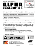
1
Vented Wall Furnaces
MODEL 737CN
MODELS 737AN, 737AP
Approved for use in Canada
Approved for use in Canada and USA
With Standard or Cast Front
WARNING: If the information in this
manual is not followed exactly, a fire or
explosion may result causing property
damage, personal injury or loss of life
- Do not store or use gasoline or other
flammable vapors and liquids in the vicinity
of this or any other appliance.
- WHAT TO DO IF YOU SMELL GAS
• Open windows
• Extinguish any open flame
• Do not try to light any appliance.
• Do not touch any electrical switch; do not
use any phone in your building.
• Immediately call your gas supplier from a
neighbor’s phone. Follow the gas
supplier’s instructions.
• If you cannot reach your gas supplier, call
the fire department.
- Installation and service must be performed by
a qualified installer, service agency or the gas
supplier.
INSTALLATION
AND
OWNER’S
MANUAL
Please read this manual
before installing and
operating
This
appliance
is
a
domestic heating appliance.
It must not be used for any
other purpose such as
drying clothes, etc.
Vous pourrez vous procurer un exemplaire en langue Française de cette brochure chez votre concessionaire.
600A754/02
CONTENTS
Page
Safety information........................................................................................................................................................... 3
General data............................................….................................................................................................................… 4
Location in room.............................................................................................................................................................. 5
Solid fuel (non-combustible) fireplaces......................................................................................................................... 5
Enclosures constructed of non-combustible materials.................................................................................................. 5
Supply gas.............................................................................................................................................................. …… 7
Pack contents....................................................................................................................................................................8
Installation........................................................................................................................................................................ 8
Pre-installation preparation........................................................................................................................................... 8
Installing to fireplace................................................................................................................................................... 10
Installing gas supply.................................................................................................................................................... 11
Assembling fuel bed.................................................................................................................................................... 12
Control operation check..............................................................................................................................................
15
Pressure checks.......................................................................................................................................................... 15
Aeration adjustment...................................................................................................................................................
15
Facia outer surround & front installation...................................................................................................................... 16
Venting check............................................................................................................................................................. 18
Final checks................................................................................................................................................................. 18
Operating procedure.................................................................................................................................................... 19
General notes............................................................................................................................................................. . 19
Lighting if spark igniter fails......................................................................................................................................... 19
Cleaning...................................................................................................................................................................... 19
Lighting instructions.................................................................................................................................................... 20
Checks........................................................................................................................................................................ 21
Servicing....................................................................................................................................................................... 22
2
SAFETY INFORMATION
Due to high temperatures, the appliance should be
located out of traffic and away from furniture and
draperies.
Keep the appliance area well clear and free from
combustible materials, gasoline and other flammable
vapors and liquids.
Children and adults should be alerted to the hazards of
high surface temperatures and should stay away to avoid
burns or clothing ignition.
If any changes are made to the room construction in the
vicinity of the appliance after installation (e.g. additional
mantle etc.) make sure that the changes conform to the
installation requirements in this manual.
Young children should be carefully supervised when they
are in the same room as the appliance.
Never attempt to burn paper or any other material in the
appliance.
Clothing or other flammable material should not be
placed on or near the appliance.
Keep the base of the appliance clear to prevent
obstruction of air flow to the appliance.
The glass and front frames must be put back in place
prior to operating the appliance if they have been
removed for servicing or cleaning.
This appliance must be properly connected to a venting
system. Models 737AN and 737AP are equipped with a
vent safety shutoff system. Operating when not connected
to a properly installed and maintained venting system or
tampering with the shutoff system on models 737AN or
737AP can result in carbon monoxide (CO) poisoning
and possible death.
The venting system should be checked periodically.
Recent trends in home improvement and new tighter
construction techniques have contributed to problems
with venting. If you suspect that your appliance is not
venting properly, do not operate. Seek expert advice.
Never operate with broken or damaged window glass.
This appliance should be installed and repaired by a
qualified service person.
The appliance should be inspected before use and at least
annually by a professional service person. More frequent
cleaning may be required due to excessive lint from
carpeting, bedding material, etc. It is imperative that
control compartments, burners and circulating air
passageways of the appliance are kept clean.
Do not use this appliance if any part has been under
water. Immediately call a qualified service technician to
inspect the appliance and to replace any part of the
control system and any gas control which has been under
water.
Keep curtains, clothing, furniture and other flammable
materials a safe distance from all parts of the appliance.
NOTE
When operating your new furnace for the first time, some vapors may be released which may cause a slight odor and could possibly set off any smoke
detection alarms in the immediate vicinity. These vapors are quite normal on new appliances. They are totally harmless and will disappear after a few
hours use.
3
1.
GENERAL
Models 737AN and 737AP are certified by International
Approval Services for use in Canada and the USA.
Model 737CN is certified by International Approval
Services for use in Canada.
The installation must conform with local codes or, in the
absence of local codes, with the current CAN/CGA-B149.1
(Natural Gas) or CAN/CGA-B149.2 (Propane) installation
code in Canada or the current National Fuel Gas Code,
ANSI Z223.1 in the USA. Only qualified licensed or trained
personnel should install the appliance.
1.1 Options
1.1.1 Furnace Front
The appliance will be supplied with the design of
front facia requested when the furnace was ordered
- Standard (louvered) or Cast Iron.
1.1.2 Facia outer surrounds
The appliance will be supplied with the design of
facia outer surround requested when the furnace
was ordered.
An alternative outer surround can be retrospectively
fitted.
The designs available are:
#777FSK 4” Black beveled trim
#778FSK 2½” Contoured black trim
#779FSK 2½” Contoured champagne trim
1.1.3 #776CFK Circulating fan kit
Operated by a variable speed control, the fan is
designed to boost the natural convection process
through the heater. This may be a desirable feature
dependent on the fireplace location and room
layout. The circulating fan may be installed during
initial appliance installation or as a retrofit at a later
date. Full installation and operating instructions are
included with the kit.
1.1.4 #770ZCK Zero clearance kit
Allows the furnace to be installed into an enclosure
constructed of combustible material. The kit must
be used in this form of enclosure. Enclosure framing
dimensions suitable for the kit are shown in section
2 of this manual. This zero clearance kit has been
designed to act as a “rough in” box with the
appliance model 737 purchased and/or fitted after
the walls of the enclosure and the hearth have been
fitted. Full installation instructions are included with
the kit.
1.1.5 #725 HACK High altitude conversion kit
Required for model 737AP only when installed at
altitudes between 2000ft and 4500ft. Consists of an
exchange regulator and associated connectors.
1.2
Rating plate
The rating plate is located on a chain. It is
accessible when the control access door is open.
1.3
Rates (Btu/h)
Altitude
(ft)
Input
(Btu/h)
OutputFan Off
OutputFan On
737AP
Max.
27,800
Min.
9,500
20004500
0-2000
25,045*
8,560*
20004500
0-2000
17,782*
0-2000
737CN, 737AN
Max.
28,500
19,740
Min.
8,500
20,235
20,990
21,075
200018,910*
4500
* With #725 HACK High altitude conversion kit
1.4
Pressures (in. w.c.)
737AP
SupplyUpstream
of
Regulator
ManifoldTapping on
Thermostat
(Appliance
full on)
1.5
Max.
14.0
Min.
11.0
9.5
9.1
737CN, 737AN
Max.
Min.
10.5
5.0
3.7
3.3
Orifice data
For verification only. Do not attempt to drill or otherwise
modify appliance input.
Model
Orifice
Type
No. of Holes Diameter
(ins.)
737AP
Pilot
Cat. 960-15
1
0.014
Front
Cat. 92-130
1
0.038
Rear
Cat. 960-190
1
0.047
737CN
Pilot
Cat. 960-45
1
0.023
737AN
Front
Cat. 82-420
7
0.029
Rear
Cat. 82-420
7
0.029
4
2. LOCATION IN THE ROOM
The appliance can be installed in the following
constructions:
Solid fuel (Non-combustible) fireplaces
2.1
As supplied, this appliance can be installed as an
inset in an existing solid fuel type fireplace with a
chimney and 3" dia liner (see fig.1a).
The fireplace must be built in accordance with the
national, state provincial or territorial building code
recognized by the authority having jurisdiction, or in
the absence of such a code, in accordance with the
National Building Code of Canada or the National
Fire Protection Association code in the USA The
size of the fireplace recess must be sufficient to
accommodate the appliance case as shown in
fig.1a.
The chimney must be swept and both chimney and
fireplace checked for soundness before installation
of the appliance. The liner must be a type approved
by the enforcing authority and installed in
accordance with the manufacturer's instructions.
The appliance must be installed on a noncombustible floor. The floor must be sufficiently flat
and level to support the appliance satisfactorily.
Some fireplace constructions have a well in the
floor at the back that may need to be filled in. In the
USA it is mandatory that a hard surfaced noncombustible hearth area must be maintained at
least 16" in front of the fireplace. This may be
2.2
Fig. 1a Solid fuel fireplace dimensions
5
finished in brick, ceramic tile, marble, etc. Raising
the hearth slightly will help to minimize dust and lint
accumulation under the unit.
In Canada, though not mandatory, we recommend
that carpet, soft vinyl or other combustible floor
coverings are kept at least 16” from the front of the
furnace since these types of materials may be
affected by the high radiant heat output from this
appliance.
The minimum clearances from any combustible
constructions at the front of the appliance are
shown in fig.1b. These front clearances apply for
all installations.
Enclosures constructed with combustible materials
#770ZCK Zero clearance kit must be installed
where the furnace is intended to be in an enclosure
made with wood studding or other combustible
materials.
The enclosure framing requirements are shown in
figures 1c through 1f.
Note that in Canada, though not mandatory, we
recommend that carpet, soft vinyl or other
combustible floor coverings are kept at least 16”
from the front of the furnace since these types of
materials may be affected by the high radiant heat
output from this appliance.
MANTLE DEPTH “A”
1”
2”
3”
4”
5”
6”
7”
CLEARANCE FROM BASE OF
HEATER “B”
37 7/8”
39 7/8”
40 7/8”
42 7/8”
44 7/8”
46 7/8”
48 7/8”
Fig. 1b Clearances to combustible materials in front of enclosure opening - All installations
Fig 1d Combustible material enclosure - For installations
in Canada with unprotected combustible floor
Fig 1c Combustible material enclosure - For installations in
USA with protected combustible floor
6
Fig 1e Combustible material enclosure - For installations in
USA with unprotected combustible floor
Fig 1f Combustible material enclosure with #770ZCK kit in
position
3. SUPPLY GAS
Models 737CN and 737AN are for use with natural gas
only. Model 737AP is for use with propane only.
The supply pressure must be between the limits shown in
section 1.4 of this manual
The supply connection is 3/8”NPT.
The supply gas feed line should enter the appliance through
one of the openings in the appliance case. Openings are at
the back and left side. (see fig.2). See section 5.3 for gas
supply connection details.
Fig. 2 Openings in case
7
4.
PACK CONTENTS
Appliances with the Standard front facia are supplied with
the facia unit fitted.
Appliances with the Cast facia are supplied with the main
appliance in one pack and the cast facia items in a
separate pack .
One of the alternative facia outer surrounds will be
included - either the standard or the deluxe outer
surround.
Cast Facia Pack contains
1
Front frame
1
Upper front Casting
1
Bottom front casting
4
Screws for frame fixing
Facia Outer Surround Pack is one of the following
alternatives:#777FSK 4”black beveled trim contains:1
Outer surround top channel (black).
2
Outer surround side channels (black)
1
Bag of screws, nuts, and washers for outer
surround fixing. or
#778FSK 2½” Contoured black trim contains:1
Outer surround top channel (black).
1
Outer surround left side channel (black).
1
Outer surround right side channel (black).
2
Corner fixing brackets.
1
Bag of screws for outer surround fixing.
or
#779FSK 2½” Contoured champagne trim contains:1
Outer surround top channel (champagne).
1
Outer surround left side channel (champagne).
1
Outer surround right side channel (champagne).
2
Corner fixing brackets.
1
Bag of screws for outer surround fixing.
Main appliance unit with Standard Facia contains:1
Main appliance fitted with window and facia units.
4
Ceramic logs.
2
Ceramic firebox side walls.
4
Ceramic base bricks.
1
Ceramic firebox back wall.
1
Inner front unit.
1
Log support plate with 2 screws
Main appliance unit for installation with Cast Facia
contains:1
Main appliance fitted with window.
4
Ceramic logs.
2
Ceramic firebox side walls.
4
Ceramic base bricks.
1
Ceramic firebox back wall.
1
Control knob
1
Control knob spacing tube
1
Log support plate with 2 screws
5. INSTALLATION
5.1
PRE-INSTALLATION PREPARATION
For installations in enclosures constructed with
combustible materials, complete the enclosure
and install the #770ZCK zero clearance kit in
accordance with the instructions supplied with the
kit.
5.1.1 Closing Large Fireplace Openings
This appliance is suitable for solid fuel fireplace
openings within the sizes shown in figure 1a.
Larger fireplace openings may be reduced or the
outer surround plate extended using noncombustible materials.
5.1.2 Remove Window and Logs (see fig.3).
5.1.2.1 Detach the window unit by removing the two
screws situated at the bottom corners of the unit.
5.1.2.2 Lift the window unit up and forwards to unhook the
top. Put the window in a safe place.
5.1.3.3 Take the ceramic logs out of the firebox and store
in a safe place
Fig. 3 Window removal (Shown with Standard Front Frame)
8
5.1.4
Appliances with Standard Front
Remove the Front Frame (See fig. 4)
Lift off the bottom louver unit. Detach the front
frame by unscrewing two screws at the top and one
screw near the bottom corners each side.
5.1.5
Remove the Vent Connection Unit
Detach the top front channel by removing two
screws and lifting clear. Detach the vent connection
unit from the top of the appliance case by removing
the screw at front. Slide the vent connection unit
back and lift clear (see fig.5).
Lift off Bottom Louver Unit
Fig. 5 Vent connector removal
5.1.6
Appliances with Cast Front
Fit the Gas Control Knob
Place the spacer tube over the control valve shaft.
Fit the control knob over the shaft pushing it firmly
on as far as it will go (see fig. 6).
Remove 4 screws
Fig. 4 Front unit removal (Standard Front Appliances)
Fig. 6 Fitting Control Knob (Cast Front Appliances)
9
5.1.7
Check Ignition Electrode Spark
Pilot ignition is by a spark produced when the
control knob is pushed in and turned counterclockwise to the (Ignition) position. Check that two
consecutive sparks are produced at the pilot
burner. If there is no spark, check that the wiring is
secure. Replace parts if necessary (see fig.7).
5.2
5.2.1
5.2.2
5.2.3
INSTALL TO FIREPLACE
Secure the collar on the vent connector unit to the
3" diameter chimney liner (Fig. 9).
Slide the fire unit into the fireplace making sure that
the vent connection unit is above the appliance
case. Leave the case front a few inches clear of
the fireplace front to allow you to fix the vent
connector to the top of the case.
Pull the vent connector towards the front of the
fireplace and locate the rear slot in the plate on the
lip at top rear of the appliance case. Fix the front of
the vent connector plate to the appliance case top
using the screw previously removed (Fig.9).
Fig. 7 Pilot ignition system
5.1.8
5.1.9
Check gas supply line routing
Openings for the gas supply line are provided at the
back and left side of the appliance case (see figure
2). The appliance is supplied with a plate covering
the back opening. The opening at the left side is
uncovered as supplied. If the supply line is to enter
through the back, remove the plate and refit to the
side opening.
Fit front log support plate
Fit the support plate using the two thread cutting
screws supplied - See figure 8.
Fig. 9 Vent connector & liner attachment
5.2.4
Fig. 8 Front Log Support Plate Fixings
10
Replace the top front channel and fix with the two
screws previously removed.
Push the appliance fully home against the front face
of the fireplace. Make sure that no sags or dips
occur in the liner.
5.3
5.3.1
5.3.2
A plugged 1/8" NPT tapping must be installed in the
line. The tapping must be accessible for test gauge
connection and be immediately upstream of the gas
supply connection to the appliance.
All piping and connections must be tested for leaks
after installation or servicing. All leaks must be
corrected immediately.
When testing for leaks:a.
Make sure that the appliance control knob
is at the OFF position.
b.
Open the manual shut-off valve.
c.
Test for leaks by applying a liquid detergent
or soap solution to all joints. Bubbles
forming indicate a gas leak.
NEVER USE AN OPEN FLAME TO
CHECK FOR LEAKS.
d.
Correct any leak detected immediately.
INSTALLATION OF GAS SUPPLY
A 3/8" NPT elbow connector is supplied for
connecting the supply line to the appliance inlet
pipe.
Use only new black iron or steel pipes or copper
tubing if acceptable. Check local codes. Note: In
USA copper tubing must be internally tinned for
protection against sulfur compounds. Unions in gas
lines should be of ground joint type.
The gas supply line must be sized and installed to
provide a supply of gas sufficient to meet the
maximum demand of the appliance without undue
loss of pressure. Sealants used for natural gas
models as well as propane versions must be
resistant to the action of all gas constituents
including L.P. gas.
Sealants should be applied lightly to male threads
to ensure excess sealant does not enter gas lines.
The supply line should include a manual shut-off
valve and union in the line to allow the appliance to
be disconnected for servicing.
Fig. 10 Gas line connection & test tapping point
11
5.4
5.4.1
ASSEMBLE FUEL BED
Install the ceramic rear wall at the back of the
firebox (see fig.11). The wall has “BASE” embossed
at the bottom. Make sure that the wall is behind the
metal channel at top of the firebox
5.4.3
Install the rear log in the two supports at rear of the
firebox. Make sure that the log is fully located in the
“V” forms of the supports (fig. 13).
Fig. 11 Rear wall location
5.4.2
Install the ceramic side walls.
The side walls are left and right handed. Rest the
bottom edges of the side walls on the firebox side
supports. Locate the top edges of the side walls in
the gaps between the edges of the top heat baffle
and the firebox sides. Slide the side walls fully back
to touch the rear wall (fig. 12).
Fig. 13 Rear log location
Fig. 12 Side wall location
12
5.4.4
Install the front base bricks. (The right hand brick
has a small notch). Place the bricks on the firebox
front ledge with the front face of the bricks behind
the lip at front of the ledge. Their inner ends should
rest on the center angled support and their outside
ends should be under the cut-outs at the front of the
side walls (fig. 14).
5.4.5
Install the side base bricks. These bricks are left
and right handed. Place the side base bricks on
the firebox side supports. The recess in the inside
edge of each brick should locate behind the vertical
metal edge of the each side support (fig. 15).
Fig. 14 Front base bricks location
Fig. 15 Side base bricks location
13
5.4.6
Install the front log. Be careful not to break the pegs
projecting from the log.
The front edge of the log should rest behind the
vertical metal edge of the firebox base which is
behind the front base bricks and front burner tube.
Be aware that there should be a gap between the
right side of the front log and the right side base
brick. There should be no gap at the left side (fig
16).
5.4.7
Install the left cross log (fig. 17).
The underside of the log is marked “L” (for left) and
“F” (for front).
Place the cross log so that the left side peg
projecting from the front log is inserted into the hole
in the cross log and with the rear of the cross log
resting in the channel in the rear log. Be careful not
to break the peg projecting from the log.
Fig. 17 Left cross log location
Fig. 16 Front log location
14
5.4.8
Install the right cross log (fig. 18).
The underside of the log is marked “R” (for right)
and “F” (for front).
Place the cross log so that the right side peg
projecting from the front log is inserted into the hole
in the cross log and with the rear of the cross log
resting on the flat area of the rear log. Be careful
not to break the peg projecting from the log. The left
branch of this cross log should rest on top of the
other cross log.
5.7
CHECK SYSTEM PRESSURE
The appliance is pre-set to give the correct heat
input with the gas for which it is designed.
The burner manifold pressure is controlled by a
built-in non-adjustable regulator.
The gas supply pressure to the appliance inlet and
the manifold pressure must be between the figures
shown in section 1.4
The manifold pressure should be checked at the
pressure test point which is located on the
thermostat unit (see fig.10). The pressure check
should be made with the appliance burning, the
valve control set at “MAX” and the thermostat
control turned to "HI".
Pressure testing supply line
The appliance and its individual shut-off valve must
be disconnected from the gas supply piping system
during any pressure testing of that system at test
pressures in excess of 1/2 psig (3.5kPa). The
appliance must be isolated from the gas supply
piping system by closing its individual manual shut
off valve during any pressure testing of the gas
supply piping system at test pressures equal to or
less than 1/2 psig (3.5kPa).
5.8
AERATION ADJUSTMENT (737CN & 737AN
Only)
On natural gas appliances both front and rear
burners are equipped with adjustable shutters to
control primary aeration. The air holes are at the
right side of the front and rear burner rails - See fig
19. The shutters can slide to the right to reduce the
air supply or to the left to increase it.
The appliance is supplied with the shutters set to
suit the vast majority of installations. No adjustment
should usually be necessary. However, in certain
installations (e.g. Low Btu value gas, high altitude) it
may be necessary to adjust the shutter position of
one or both of the burners to obtain the optimal
visual effect.
Aeration is not adjustable on Propane
appliances (Model #737AP)
Fig. 18 Right cross log location
5.5
5.5.1
5.5.2
5.6
REFIT THE WINDOW
Hook the top of the window frame over the firebox
top front edge.
Secure the window unit in place by refitting two
screws at the bottom corners of the unit.
CHECK OPERATION ON CONTROLS
Check ignition, valve control and thermostat
settings as described in the lighting instructions
section further on in this manual.
Fig. 19 Aeration shutters
15
5.9
INSTALL FACIA OUTER SURROUND TO FRONT
FRAME
The outer surrounds are supplied disassembled.
The top and side channels will have to be
connected as described below.
5.9.1 With #777FSK 4” beveled trim
5.9.1.1 Assemble the two outer surround sides to the top
cross piece using four nuts, screws and washers
provided (fig. 20).
5.9.2 With #778FSK or #779FSK 2½” contoured trim
5.9.2.1 Assemble the left and right side channels to the top
channel using the corner fixing brackets and 8
thread cutting screws provided (fig.22).
Fig. 22 #778FSK and #779FSK assembly
Fig. 20 #777FSK assembly
5.9.2.1 Attach the outer facia to the front frame with 4
thread cutting screws provided (fig.23).
5.9.1.2 Attach the outer facia to the front frame with the
four nuts, bolts and washers supplied (fig. 21).
Fig. 23 #778FSK and #779FSK surround to front frame
attachment
Fig. 21 #777FSK surround to front frame attachment
16
5.10
APPLIANCES WITH STANDARD FRONT
INSTALL THE FRONT TO THE APPLIANCE
5.10.1 Attach the front frame to the appliance with two
screws previously removed at the top and one near
the bottom corners each side (see fig. 24).
5.10.3 Locate the hooks on the inner front unit into the
slots at each side of the fire box. Push the inner
front fully downwards (fig, 26).
Fig. 26 Inner front unit attachment
(Standard front appliances)
Fig. 24 Front Frame Attachment
5.10.2 Hook the bottom louver unit on to the brackets near
the bottom of the frame sides (see fig. 25).
Take care not to trap any wires or thermostat parts
between the frame and appliance case.
Make sure that the thermostat control wheel is free
to rotate in the opening in the frame side.
5.11
APPLIANCES WITH CAST FRONT
5.11.1 Attach the front frame to the appliance with two
screws at the top and one near the bottom corners
each side (see fig. 24).
5.11.2 Attach the bottom front casting by hooking the two
steel locators at back of the casting over the
brackets at the bottom of the front frame sides (see
fig. 27).
Fig. 25 Bottom Louver Attachment (Standard Front)
Fig. 27 Bottom Front Casting Location
17
5.11.3 Rest the upper front casting on the bottom casting.
Then slightly lift the upper casting and attach it to
the appliance by hooking the two steel locators at
back of the casting over the brackets inside the top
corners of the front frame (see fig. 28).
5.13
5.13.1
5.13.2
5.13.3
5.13.4
5.13.5
Fig. 28 Upper Front Casting Location
5.12
5.12.1
5.12.2
5.12.3
5.12.4
CHECK VENTING EFFICIENCY
A check for correct venting of combustion products
must be made before the installed appliance is left
with the customer.
Ignite the pilot. Turn the main control valve to the
fully on position marked z. Turn the thermostat
wheel to “HI”.
Leave for 15 minutes.
Using a piece of cardboard from the packaging or
similar material, cut a section approximately 12”
square.
Light a long match. Hold the piece of cardboard
immediately below the slots at top of the front unit
and near the center. This will prevent the
convection air from interfering with the test. Insert
the match into one of the slots near the center (Fig.
29). The installation is satisfactory if the smoke is
drawn into the appliance.
Fig. 29 Venting check
5.12.5 If the smoke spills out of the slots, inspect the
sealing at the vent connection unit.
5.12.6 If the sealing is satisfactory but the smoke still spills
out, turn the appliance off and check the vent
18
system thoroughly for cause of lack of pull. If
necessary get expert advice. Do not let the
appliance be operated without correct venting.
FINAL CHECK
Recheck gas control and thermostat operation.
Instruct the owner how to operate the appliance.
Point out the location of the supply shut-off valve
and how to close it.
Close the bottom hinged grill
Recommend that the appliance should be
inspected and, if necessary serviced at least once a
year.
6. OPERATING PROCEDURE
For full lighting instructions see next page.
The operating instructions are also on a chain at bottom of
the appliance.
6.1 GENERAL OPERATING NOTES
6.1.1 For your safety this appliance is fitted with a flame
supervision device which will shut off the gas
supply if, for any reason, the pilot flames go out.
This device incorporates a fixed probe which
senses the heat from the pilot flame. If the probe
is cool, the device will prevent any gas flow unless
the gas control knob is kept pushed in between
the } (Off) and
(Ignition) positions.
6.1.2
6.1.3
6.1.4
6.2
LIGHTING IF SPARK IGNITER FAILS
In the unlikely event of failure to create an ignition spark
using the control knob, the appliance can be lit as
follows:
6.2.1.1 Appliances with Standard Front: Remove the inner
front unit by lifting its hooks clear of the supporting
pegs (see fig. 26).
6.2.1.2 Appliances with Cast Front: Remove the top and
bottom front castings by lifting them off their
supporting brackets. See figures 27 and 28.
6.2.2 Remove the window unit (see fig. 3).
6.2.3 Insert a long burning match at the pilot.
6.2.4 Operate the controls as described in the lighting
instructions.
6.2.5 Make sure that the pilot flame is stable.
6.2.6 Replace the window unit securely.
6.2.8 Replace the inner front (for standard front
appliances) or castings (for cast front appliances).
.
6.3
CLEANING
6.3.1 Only clean when the appliance is cold.
6.3.2 Normally, the appliance should only need dusting.
Any stains on the ceramic glass window can be
removed with a non-abrasive cleaner. Never use
abrasive cleaners on the glass.
6.3.3 Dust, etc. can be brushed from the ceramic logs,
base bricks and side walls after detaching the
inner front unit and window. If you are removing
the ceramic parts, we suggest that they are
removed in the reverse order to that shown in the
fuel bed assembly section of this manual (Section
5.4).
Dust etc. can also be removed from the burners
using a soft brush after removing the logs. When
cleaning the burners also check the aeration holes
(see fig.19) and brush clean if necessary. Make
sure that no particles are brushed into the burner
tubes.
6.3.4 Coloring of the interior of the metal fire box with use
is normal. Do not try to remove the color with
abrasive materials.
The Valor Comfostat™ Temperature control
system
Conventional
thermostats
regulate
the
temperature by shutting the burners off when the
temperature reaches its upper limit. This gives
stop-go heat, unnaturally varying flames and
impaired efficiency (like a car in city traffic). The
Comfostat™ system controls the temperature by
gradually lowering or raising the fire. This
maintains room comfort by providing steadier heat
and a more natural looking regulation of the
flames.
The control wheel at the top right side controls the
thermostat operating temperature. The room
temperature will be maintained at the desired level
for any setting up to just short of the “HI” position.
The “HI” position is an override which will keep the
fire fully on all the time and is not affected by room
temperature.
When first turned on, the decorative flames will
appear predominantly blue. After approximately
15 minutes the flames will turn yellow.
After approximately three hours use at the high
control setting the fuel pieces will show areas of
charcoal gray color as would real burning logs.
19
FOR YOUR SAFETY READ BEFORE LIGHTING
WARNING: If you do not follow these instructions exactly, a fire or explosion may result causing property damage,
personal injury or loss of life.
A. This appliance has a pilot which must be lighted by hand. When lighting the pilot, follow these instructions
exactly.
B. BEFORE LIGHTING smell all around the appliance area for gas. Be sure to smell next to the floor because some
gas is heavier than air and will settle on the floor.
WHAT TO DO IF YOU SMELL GAS
• Do not try to light any appliance.
• Do not touch any electric switch; do not use any phone in your building.
• Immediately call your gas supplier from a neighbor’s phone. Follow the gas supplier’s instructions.
• If you cannot reach your gas supplier, call the fire department.
C. Use only your hand to push in or turn the gas control knob. Never use tools. If the knob will not push in or turn
by hand, don’t try to repair it, call a qualified service technician. Force or attempted repair may result in a fire or
explosion.
D. Do not use this appliance if any part has been under water. Immediately call a qualified service technician to
inspect the appliance and to replace any part of the control system and any gas control which has been under
water.
LIGHTING INSTRUCTIONS
1.
STOP! Read the safety information above on this page.
Pilot unit
Thermostat wheel
2.
3.
4.
5.
6.
7.
8.
9.
Gas control knob
Set the thermostat to its lowest setting (“LO”).
Turn the gas control knob clockwise
to } (off).
Note; Knob cannot be turned from
(ignition) to } (off) unless it is pushed in partially. Do not force.
Wait five (5) minutes to clear out any gas. If you then smell any gas, STOP! Follow “B” in the safety information
above. If you don’t smell gas, go to next step.
Find the pilot. It is at the right side of the firebox.
until resistance is felt just before the
Push in and turn the gas control knob counter- clockwise
(ignition) position.
Keep pushed in for a few seconds to allow gas to flow then, keeping knob depressed, turn to to light pilot.
Hold knob in for a further 5 seconds then release. The knob should pop back out. The pilot should remain lit. If
pilot goes out repeat steps 3 through 7. If pilot does not light at all during a few attempts, try lighting with a long
match as described below.
• If knob does not pop out when released, stop and immediately call your service technician or gas supplier.
• If pilot lights but will not stay lit after several tries, turn the gas control knob to } (off) and call your service
technician or gas supplier.
When pilot is lit, partially depress the knob and turn to y (burners alight) position.
• Do not leave knob set between and y .
Set thermostat to desired setting.
Match lighting: Apply a long match to the pilot while control knob is pushed in and at the position - See
previous page for full details.
• Always replace the window unit after match lighting the pilot.
• The gas control knob should always pop out when released. If it does not, stop and immediately call your
service technician or gas supplier.
TO TURN OFF GAS TO APPLIANCE
1.
2.
Set the thermostat to lowest setting (“LO”).
Push in control knob slightly and turn clockwise
to } (off). Do not force.
20
6.4
6.4.1
6.4.2
CHECKS
A periodic visual check of the pilot and burner
flames should be made (see figs 30 and 31).
Check after the furnace has been on for at least 30
minutes.
The appliance area must always be kept clear and
free from combustible materials, gasoline and other
flammable vapors and liquids.
6.4.3
6.4.4
Keep the area in front at the bottom of the
appliance clear. Obstructions will impede the flow
of air to the appliance and cause incorrect
combustion.
The flow of combustion and ventilation air must not
be obstructed. The venting system should be
examined by a qualified agency regularly. We
suggest annually.
Fig. 31 Pilot flame
CORRECT MODELS 737CN, 737AN
CORRECT MODEL 737AP
WRONG
Fig. 30 Burner flames
21
7. SERVICING
The repair parts are shown on the repair parts leaflet.
Please always quote Part Number and description with
requests for spares.
7.1
7.2.4
Remove the front frame as described in installation
instructions section 5.1.4.
7.2.5 Disconnect the gas supply line elbow at the
appliance inlet pipe union.
7.2.6 Disconnect the thermostat shaft from the
thermostat (Fig. 32).
7.2.7 Detach the front log support plate by removing two
screws (See fig. 8)
7.2.8 Detach the burner module by removing 7 screws
(Fig. 33)
7.2.9 Carefully slide the burner module forward until just
clear of the appliance case.
7.2.10 Models 737AN & 737AP: For most servicing
operations, the vent shut off switch wires can
remain attached to the burner module. If the burner
module must be completely removed from the
appliance area, loosen the thermocouple connector
at back of the gas valve to detach the wires (Fig
34).
7.2.11 Model 737AN & 737AP: When refitting, Be sure to
secure the shut off switch wires behind the
thermostat bracket at the right side of the module
(Fig.35).
For Owner
If you require any attention to your appliance,
contact your supplier quoting the model number. It
is helpful if the appliance serial number is also
quoted. This will be found on the appliance rating
plate which is on a chained plate accessible when
the bottom grill is open.
7.2
For Service Engineer
To aid servicing of the burner and manifold parts,
the burner module can be removed as follows:
7.2.1.1 Appliances with Standard Front: Remove the inner
front unit by lifting its hooks clear of the supporting
pegs (see fig. 26).
7.2.1.2 Appliances with Cast Front: Remove the top and
bottom front castings by lifting them off their
supporting brackets. See figures 27 and 28.
7.2.2 Remove the window unit (see fig. 3).
7.2.3 Take all the ceramic parts out of the firebox and
carefully store.
Fig. 32 Thermostat shaft disconnection
Fig. 33 Burner module disconnection points
Fig. 34 Shut off switch wires connection (Models 737AN &
737AP)
22
Fig. 35 Shut off wires location (Models 737AN & 737AP)
Manufactured by
HEATING
BIRMINGHAM, ENGLAND
Because our policy is one of constant development and improvement, details may vary slightly from those given in this publication.
© Valor Ltd. 1995, 1997
23