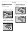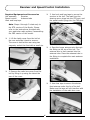
1
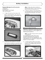
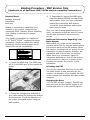
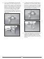
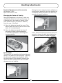
® 29-inch Brushless-Powered Catamaran Owners Manual PRB4075 (PNP) and PRB4075S (RTR) Specifications Length........................................................................................... 30 in (762mm) Beam............................................................................................. 11 in (279mm) Motor............................................................A3630-1800Kv Water-Cooled Brushless Receiver............................. Spektrum 2.4GHz Marine (not included with PNP version) Speed Control............................................................. 60-amp Waterproof Brushless Hull Material........................................................................... Fiberglass Composite Battery....... 7.4V 2S 30C Li-Po or 7.2V Sub-C with Deans Connector (2) (not included) Radio........................................................2-channel (not included with PNP version) www.ProBoatModels.com Notice All instructions, warranties and other collateral documents are subject to change at the sole discretion of Horizon Hobby, Inc. For up-to-date product literature, visit http://www. horizonhobby.com and click on the support tab for this product. Meaning of Special Language The following terms are used throughout the product literature to indicate various levels of potential harm when operating this product: NOTICE: Procedures, which if not properly followed, create a possibility of physical property damage AND a little or no possibility of injury. CAUTION: Procedures, which if not properly followed, create the probability of physical property damage AND a possibility of serious injury. WARNING: Procedures, which if not properly followed, create the probability of property damage, collateral damage, and serious injury OR create a high probability of superficial injury. WARNING: Read the ENTIRE instruction manual to become familiar with the features of the product before operating. Failure to operate the product correctly can result in damage to the product, personal property and cause serious injury. Country of Purchase United States of America Horizon Hobby Horizon Service Center (Electronics and engines) Address 4105 Fieldstone Rd Champaign, Illinois 61822 USA Phone Number/Email Address 877-504-0233 Online Repair Request visit: www.horizonhobby.com/repairs Horizon Product Support (All other products) 4105 Fieldstone Rd Champaign, Illinois 61822 USA 877-504-0233 [email protected] Horizon Hobby Limited Units 1-4 Ployters Rd Staple Tye Harlow, Essex CM18 7NS United Kingdom +44 (0) 1279 641 097 [email protected] Germany Horizon Technischer Service Hamburger Str. 10 25335 Elmshorn Germany +49 4121 46199 66 [email protected] France Horizon Hobby SAS 14 Rue Gustave Eiffel Zone d’Activité du Réveil Matin 91230 Montgeron United Kingdom +33 (0) 1 60 47 44 70 [email protected] This is a sophisticated hobby product and NOT a toy. It must be operated with caution and common sense and requires some basic mechanical ability. Failure to operate this Product in a safe and responsible manner could result in injury or damage to the product or other property. This product is not intended for use by children without direct adult supervision. Do not attempt disassembly, use with incompatible components or augment product in any way without the approval of Horizon Hobby, Inc. This manual contains instructions for safety, operation and maintenance. It is essential to read and follow all the instructions and warnings in the manual, prior to assembly, setup or use, in order to operate correctly and avoid damage or serious injury. Table of Contents Recommended Tools and Adhesives......................................................................... 3 Recommended Batteries......................................................................................... 3 General Guidelines and Safety Precautions............................................................... 3 Assembly............................................................................................................. 4 Receiver and Speed Control Installation................................................................... 5 Battery Installation................................................................................................ 6 Binding Procedure - PNP Version Only................................................................7 Handling Adjustments............................................................................................ 9 Maintenance....................................................................................................... 10 Limited Warranty................................................................................................. 11 Regulatory Information........................................................................................ 13 FCC Information (RTR Version).............................................................................. 13 Regulatory Information........................................................................................ 14 Item Identification............................................................................................... 15 Replacement Parts............................................................................................... 15 2 Recommended Tools and Adhesives • • • • • Needle nose pliers Marine grease (PRB0100 or PRB0101) Paper towel Rubbing alcohol Open end wrench: 7mm, 10mm • • • • Phillips screwdriver: #1 Hex wrench: 2.5mm, 3mm Clear tape (PRB0102) Hook and loop tape Recommended Batteries Batteries We recommend the purchase of two of the following batteries (Model requires two batteries to operate): • PRB3316 7.2V 5100mAh Ni-MH with Deans Connector • DYN5301D 7.4V 3200mAh 30C Li-Po with Deans Connector • DYN5302D 7.4V 4200mAh 30C Li-Po with Deans Connector • DYN5303D 7.4V 5300mAh 30C Li-Po with Deans Connector • DYN5304D 7.4V 6000mAh 30C Li-Po with Deans Connector www.dynamiterc.com NOTICE: Use of Ni-MH batteries requires the purchase of the Brushless ESC Programming Module (PRB3311) (not included) as ESC is factory set for use with Li-Po batteries. General Guidelines and Safety Precautions It is important that you read and follow this instruction manual, along with the radio system manual before you run this exciting boat. Failure to read and understand the manual could result in personal injury, property damage or permanent damage to your boat. It is also important to run your boat responsibly. With proper care and maintenance, you will be able to proudly enjoy your Mystic 29 BL for many years to come. Check all of the hardware, and the propeller, for damage and loose screws before and after each run. If at any time while operating your model you sense any abnormal function, end your operation immediately. Do not operate your boat again until you are certain the problem has been corrected. Always stay clear of the propeller. Age Recommendation: Not for Children under 14 years. This is not a toy. When operating the boat, stay clear of people, full-scale boats, stationary objects and wildlife. It is preferable to operate the Mystic 29 BL in low wake, low wind conditions and in areas free of people, wildlife and objects. 3 Assembly Required Equipment and Accessories 3. Install the four AA batteries in the battery holder. Match the polarity of the batteries to the molded markings in the battery holder. Transmitter AA battery (4) Motor battery (2) (charged) Hook and loop tape 1. Locate the pieces for the boat stand. The longer side pieces will key to the shorter end pieces. Use a small amount of Medium CA to glue the pieces together. 4. Slide the battery cover back on the bottom of the transmitter. Note: Steps 2 through 4 relate only to the RTR version of the Mystic. Please refer to the instructions provided with your particular radio system if assembling the PNP version of this model. 2. Slide the cover from the bottom of the transmitter to access the battery holder. 4 Receiver and Speed Control Installation Required Equipment and Accessories 3. Use hook and loop tape to secure the receiver in the hull. The lead from the steering servo plugs into the STR port, and the speed control plugs into the THR port. Hull assembly Receiver Speed control Antenna tube Hook and loop tape Note: Steps 4 through 5 relate only to the RTR version of the Mystic. Please refer to the instructions provided with your particular radio system if assembling the PNP version of this model. 1. Lift the hatch cover from the hull at the rear and slide it back to remove. The cover is held at the rear using two magnets, and at the front with a small pin. 4. Pass the longer antenna wire through the fitting on the top of the hull. The antenna wire is then inserted into the antenna tube. Place the antenna tube in the fitting to complete the main antenna installation. 2. Remove the radio box cover from the hull by lifting it up using the tab at the rear of the cover. 5. Use clear tape to secure the shorter feed antenna under the lip of the hull. Make sure the tape will not interfere with the installation of the radio box cover. 5 Battery Installation Required Equipment and Accessories Note: Center the trims for both the steering and throttle on your transmitter before turning the transmitter on. Transmitter AA battery (4) Motor battery (2) (charged) Hook and loop tape 3. Move the switch on the transmitter to the ON position and confirm that the red and green LED illuminate. Turn off the transmitter. 1. Apply the hook and loop tape to the bottom of both batteries. Also apply the mating piece of tape in the hull where the batteries will be located. About your Speed Controller Be sure to use a Programming Module (PRB3311) to adjust the cutoff voltage when using Ni-MH batteries to protect against overdischarging the batteries. Note: The ESC is factory-set for use with Li-Po batteries. The programming module offers other beneficial adjustments like exponential throttle curves and timing adjustments. Visit ProBoatModels.com and search "Programming Module" for further details. 4. Confirm that the ESC on/off switch is in the "OFF" position and connect the batteries to the battery plugs from the speed control. 2. Place the motor batteries in the hull. There will be one battery on the left of the hull, and one on the right side of the hull. 6 Binding Procedure - PNP Version Only (Applicable to all Spektrum DSM 2.4GHz marine compatible transmitters) Required Parts 3. Remember to remove the BIND plug from the receiver BEFORE turning off the radio system. Once you have completed binding the transmitter and receiver, unplug the motor batteries and remove them from the boat. Fuselage assembly Transmitter Bind plug Binding is connecting a transmitter to a receiver so the receiver recognizes the transmitter GUID (Globally Unique Identifier) code. Binding is necessary for proper operation. Once you have finished programming your radio, you should re-bind the radio to ensure the fail-safe positions for the servos are correct. Your model is compatible to a Spektrum™ or JR® DSM2™/DSMX™-equipped full range transmitter. Spektrum radios with marine technology use the following boat icon to indicate marine use compatibility: Additional Information Regarding Your Radio System Before each run, power on the transmitter and wait about five (5) seconds before moving the receiver switch to the ON position. When the receiver is switched on too quickly for the transmitter to make frequency selection, the transmitter and receiver may not connect. When there is no connection, leave the transmitter powered on, turn off the receiver switch then turn it back on to power up the receiver and connect the receiver to the transmitter. 1. Locate the BIND plug. The BIND plug will fit in the BIND port of the receiver as shown. Activating the ESC Turn on the transmitter then turn on the ESC. The radio system is now searching for the receiver it is bound to. Once located, the LED on the receiver will illuminate and allow rudder operation. Engaging the Motor Turn the ESC off then on again. The ESC will beep until you pull the throttle trigger to full throttle and return it to the neutral position. 2. Follow the procedure as described in your radio manual for binding the receiver and transmitter. Check the operation of the rudder and speed control using the radio system. 7 4. Turn on the transmitter, then the ESC on/off switch. The ESC will beep until you pull the throttle trigger to full throttle and return it to the neutral position. Check the operation of the propeller in relationship to the throttle trigger. When the trigger is pulled in, the propeller must rotate counterclockwise as shown. If the motor turns in the wrong direction, switch any 2 motor wires. 5. Check the operation of the steering in relationship to the steering wheel. When the wheel is rotated clockwise, the rudder must move right as shown. If not, follow the instructions from the radio to set the servo reversing for the steering. 6. Place the clear battery cover back into position. We suggest using clear tape (PRB0102) around the edge of the main hatch to keep it in place in the event of a roll over. 8 Handling Adjustments Required Equipment and Accessories Raising the drive helps eliminate oscillation or bouncing and assist with top end stability but excessively raising the drive can reduce top speeds and cause cavitation. Hex wrench: 3mm Open-end wrench: 7mm Changing the Center of Gravity Moving the batteries to the front or back can significantly affect the boat's performance. As a starting point, the center of gravity of the boat should be 30% (9-inches or 228mm) from the rear of the boat. A: M ove the batteries toward the rear of the boat to raise the front of the hull out of the water for increased speed. B: M ove the batteries toward the front of the boat for faster initial acceleration, to eliminate oscillation or bouncing and increase stability. Use a 3mm hex wrench and 7mm open-end wrench to loosen the bolt that attaches the output to the bracket to adjust the height. A B Drive Height The center of the propeller shaft should be just about to the bottom of the sponsons. Lowering the drive will increase the propeller's ability to bite at take off but excessive lowering can cause the back of the boat to feel loose and decrease top end stability. 9 Maintenance Required Tools and Lubricants 3. Use a paper towel and rubbing alcohol to clean the flex shaft. Marine grease Paper towel Rubbing alcohol Open-end wrench: 10mm (2) Hex wrench: 2.5mm Nut driver: 4mm Lubricating the Flex Shaft Lubricating the drive system is vital to the life of the drivetrain. The lubricant also acts as a water seal, keeping water from entering the hull through the stuffing box. Lubricate the drive shaft, propeller shaft and all moving parts after every 2–3 hours of operation. 4. Apply a waterproof marine grease to the flex shaft. We recommend the Pro Boat marine grease available at your local hobby dealer. 1. Use two 10mm open-end wrenches to loosen the ferrule that secures the flex shaft to the motor. 5. Reverse the previous steps to reinstall the flex drive. Check that there is a slight gap of 1/32-inch (1mm) between the stuffing box and propeller mount as shown. 2. Remove the flex shaft by pulling it out of the stuffing box by the propeller. 10 Limited Warranty What this Warranty Covers nor accepted for any resulting damage or injury. By the act of use, setup or assembly, the user accepts all resulting liability. If you as the purchaser or user are not prepared to accept the liability associated with the use of the Product, purchaser is advised to return the Product immediately in new and unused condition to the place of purchase. Horizon Hobby, Inc. (“Horizon”) warrants to the original purchaser that the product purchased (the "Product") will be free from defects in materials and workmanship at the date of purchase. What is Not Covered This warranty is not transferable and does not cover (i) cosmetic damage, (ii) damage due to acts of God, accident, misuse, abuse, negligence, commercial use, or due to improper use, installation, operation or maintenance, (iii) modification of or to any part of the Product, (iv) attempted service by anyone other than a Horizon Hobby authorized service center, or (v) Products not purchased from an authorized Horizon dealer. OTHER THAN THE EXPRESS WARRANTY ABOVE, HORIZON MAKES NO OTHER WARRANTY OR REPRESENTATION, AND HEREBY DISCLAIMS ANY AND ALL IMPLIED WARRANTIES, INCLUDING, WITHOUT LIMITATION, THE IMPLIED WARRANTIES OF NON-INFRINGEMENT, MERCHANTABILITY AND FITNESS FOR A PARTICULAR PURPOSE. THE PURCHASER ACKNOWLEDGES THAT THEY ALONE HAVE DETERMINED THAT THE PRODUCT WILL SUITABLY MEET THE REQUIREMENTS OF THE PURCHASER’S INTENDED USE. Law These terms are governed by Illinois law (without regard to conflict of law principals). This warranty gives you specific legal rights, and you may also have other rights which vary from state to state. Horizon reserves the right to change or modify this warranty at any time without notice. Warranty Services Questions, Assistance, and Services Your local hobby store and/or place of purchase cannot provide warranty support or service. Once assembly, setup or use of the Product has been started, you must contact Horizon directly. This will enable Horizon to better answer your questions and service you in the event that you may need any assistance. For questions or assistance, please direct your email to productsupport@horizonhobby. com, or call 877.504.0233 toll free to speak to a Product Support representative. You may also find information on our website at www.horizonhobby. com. Purchaser’s Remedy Horizon’s sole obligation and purchaser’s sole and exclusive remedy shall be that Horizon will, at its option, either (i) service, or (ii) replace, any Product determined by Horizon to be defective. Horizon reserves the right to inspect any and all Product(s) involved in a warranty claim. Service or replacement decisions are at the sole discretion of Horizon. Proof of purchase is required for all warranty claims. SERVICE OR REPLACEMENT AS PROVIDED UNDER THIS WARRANTY IS THE PURCHASER’S SOLE AND EXCLUSIVE REMEDY. Inspection or Services If this Product needs to be inspected or serviced, please use the Horizon Online Service Request submission process found on our website or call Horizon to obtain a Return Merchandise Authorization (RMA) number. Pack the Product securely using a shipping carton. Please note that original boxes may be included, but are not designed to withstand the rigors of shipping without additional protection. Ship via a carrier that provides tracking and insurance for lost or damaged parcels, as Horizon is not responsible for merchandise until it arrives and is accepted at our facility. An Online Service Request is available at http://www.horizonhobby.com under the Support tab. If you do not have internet access, please contact Horizon Product Support to obtain a RMA number along with instructions for submitting your product for service. When calling Horizon, you will be asked to provide your complete name, street address, email address and phone number where you can be reached during business hours. When sending product into Horizon, please include your RMA number, a list of the included items, and a brief summary of the problem. A copy of your Limitation of Liability HORIZON SHALL NOT BE LIABLE FOR SPECIAL, INDIRECT, INCIDENTAL OR CONSEQUENTIAL DAMAGES, LOSS OF PROFITS OR PRODUCTION OR COMMERCIAL LOSS IN ANY WAY, REGARDLESS OF WHETHER SUCH CLAIM IS BASED IN CONTRACT, WARRANTY, TORT, NEGLIGENCE, STRICT LIABILITY OR ANY OTHER THEORY OF LIABILITY, EVEN IF HORIZON HAS BEEN ADVISED OF THE POSSIBILITY OF SUCH DAMAGES. Further, in no event shall the liability of Horizon exceed the individual price of the Product on which liability is asserted. As Horizon has no control over use, setup, final assembly, modification or misuse, no liability shall be assumed 11 Non-Warranty Service original sales receipt must be included for warranty consideration. Be sure your name, address, and RMA number are clearly written on the outside of the shipping carton. Notice: Do not ship LiPo batteries to Horizon. If you have any issue with a LiPo battery, please contact the appropriate Horizon Product Support office. Should your service not be covered by warranty service will be completed and payment will be required without notification or estimate of the expense unless the expense exceeds 50% of the retail purchase cost. By submitting the item for service you are agreeing to payment of the service without notification. Service estimates are available upon request. You must include this request with your item submitted for service. Non-warranty service estimates will be billed a minimum of ½ hour of labor. In addition you will be billed for return freight. Horizon accepts money orders and cashiers checks, as well as Visa, MasterCard, American Express, and Discover cards. By submitting any item to Horizon for service, you are agreeing to Horizon’s Terms and Conditions found on our website http://www. horizonhobby.com/Service/Request/. Warranty Requirements For Warranty consideration, you must include your original sales receipt verifying the proof-of-purchase date. Provided warranty conditions have been met, your Product will be serviced or replaced free of charge. Service or replacement decisions are at the sole discretion of Horizon. Warranty and Service Contact Information Country of Purchase Horizon Hobby Address Phone Number/Email Address Horizon Service Center (Electronics and engines) 4105 Fieldstone Rd Champaign, Illinois 61822 USA 877-504-0233 Online Repair Request visit: www.horizonhobby.com/repairs Horizon Product Support (All other products) 4105 Fieldstone Rd Champaign, Illinois 61822 USA 877-504-0233 [email protected] United Kingdom Horizon Hobby Limited Units 1-4 Ployters Rd Staple Tye Harlow, Essex CM18 7NS United Kingdom +44 (0) 1279 641 097 [email protected] Germany Horizon Technischer Service Hamburger Str. 10 25335 Elmshorn Germany +49 4121 46199 66 [email protected] France Horizon Hobby SAS 14 Rue Gustave Eiffel Zone d’Activité du Réveil Matin 91230 Montgeron +33 (0) 1 60 47 44 70 [email protected] Horizon Hobby Address Phone Number/Email Address Sales 4105 Fieldstone Rd Champaign, Illinois 61822 USA (800) 338-4639 [email protected] United Kingdom Horizon Hobby Limited Units 1-4 Ployters Rd Staple Tye Harlow, Essex CM18 7NS United Kingdom +44 (0) 1279 641 097 [email protected] Germany Horizon Hobby GmbH Hamburger Str. 10 25335 Elmshorn Germany +49 4121 46199 60 [email protected] France Horizon Hobby SAS 14 Rue Gustave Eiffel Zone d’Activité du Réveil Matin 91230 Montgeron +33 (0) 1 60 47 44 70 [email protected] United States of America Customer Service Information Country of Purchase United States Register your new boat at www.ProBoatModels.com 12 Regulatory Information FCC Information (RTR Version) Antenna Separation Distance (RTR Version) When operating your transmitter, please be sure to maintain a separation distance of at least 5 cm between your body (excluding fingers, hands, wrists, ankles and feet) and the antenna to meet RF exposure safety requirements as determined by FCC regulations. The illustrations below show the approximate 5 cm RF exposure area and typical hand placement when operating your transmitter. This device complies with part 15 of the FCC rules. Operation is subject to the following two conditions: (1) This device may not cause harmful interference, and (2) this device must accept any interference received, including interference that may cause undesired operation. Caution: Changes or modifications not expressly approved by the party responsible for compliance could void the user’s authority to operate the equipment. This product contains a radio transmitter with wireless technology which has been tested and found to be compliant with the applicable regulations governing a radio transmitter in the 2.400GHz to 2.4835GHz frequency range. 13 Compliance Information for the European Union AT BG CZ CY DE DK ES FI FR GR LU HU IE IT LT LV MT NL PL PT RO SE SI SK UK Declaration of Conformity (in accordance with ISO/IEC 17050-1) PRB4075S Declaration of Conformity (in accordance with ISO/IEC 17050-1) No. HH2011052902 No. HH2011052901 Product(s): Item Number(s): Product(s):Mystic Catamaran 29 BL RTR Item Number(s): PRB4075S Equipment class: 2 The object of declaration described above is in conformity with the requirements of the specifications listed below, following the provisions of the European R&TTE directive 1999/5/EC: EN EN EN EN 300-328 V1.7.1 301 489-1 V1.7.1: 2006 301 489-17 V1.3.2: 2008 60950-1:2006+A11 Signed for and on behalf of: Horizon Hobby, Inc. Champaign, IL USA May 29, 2011 Mystic Catamaran 29 BL PNP PRB4075 Equipment class: 1 The object of declaration described above is in conformity with the requirements of the specifications listed below, following the provisions of the European R&TTE directive 1999/5/EC: EN 301 489-1 V1.7.1: 2006 EN 301 489-3 V1.4.1: 2008 Signed for and on behalf of: Horizon Hobby, Inc. Champaign, IL USA May 29, 2011 Steven A. Hall Vice President International Operations and Risk Management Steven A. Hall Horizon Hobby, Inc. Vice President International Operations and Risk Management Horizon Hobby, Inc. Instructions for Disposal of WEEE by Users in the European Union This product must not be disposed of with other waste. Instead, it is the user’s responsibility to dispose of their waste equipment by handing it over to a designated collection point for the recycling of waste electrical and electronic equipment. The separate collection and recycling of your waste equipment at the time of disposal will help to conserve natural resources and ensure that it is recycled in a manner that protects human health and the environment. For more information about where you can drop off your waste equipment for recycling, please contact your local city office, your household waste disposal service or where you purchased the product. 14 Item Identification Cooling Line Rudder Linkage Receiver Steering Servo Switch Rudder Motor Stuffing Box Speed Control Propeller Hull Antenna Hatch Cover Water Outlet Radio Box Cover Stand * Decals not shown for clarity Replacement Parts Go to ProBoatModels.com to see photos of the replacement parts listed under Mystic 29 BL. If you have any questions concerning the setup or running of your model, please see pages 12 to contact the appropriate Horizon service center. PRB3308 Cable Collet PRB4018 60-AMP Brushless ESC PRB4017 A3630-1800 Brushless Motor PRB3311Brushless ESC Programming Module PRB3312 Tamiya/Deans Charge Adapter PRB3315 Antenna Mount PRB0100 Marine Grease PRB0101 Marine Grease Refill 5 oz PRB0102 Clear Flex Tape PRB2239 Drain Plug PRB4079Decal PRB4076 Hull and Canopy PRB4077Canopy PRB4103 Radio Box Cover PRB4104 Boat Stand PRB4105 Prop Strut PRB4078 Rudder with Strut PRB4107Flexshaft PRB4108 Drive Dog PRB4109 Prop Nut PRB4110 Stuffing Box PRB4111 Rudder Pushrod Set PRB2068 Water Outlet PRB40191.6" x 2.5" Stainless Steel Propeller PRB2288 Nylon Washer PRB2223 Push Rod Connector PRB2224 Silicone Tubing PRB4012 Antenna Tube PRB2073 Rubber Boot PRB3307 Motor Mount RTR Items Only PRB8060 Pistol-Grip 2.4GHz Transmitter Only PRB8061 MS113DS Digital Servo SPMMR200MR200 Marine 2.4GHz 2-Channel Sport Receiver 15 ® Mystic is a trademark of mystic Powerboats Inc. and is used with permission by Horizon Hobby, Inc. The Spektrum trademark is used with permission of Bachmann Industries, Inc. Pro Boat, DSM2 and DSMX are trademarks or registered trademarks of Horizon Hobby, Inc. JR is a trademark of Horizon Hobby, Inc., registered in the U.S. US 7,391,320. Other patents pending. Printed 04/2011 © 2011 Horizon Hobby, Inc. horizonhobby.com www.proboatmodels.com 30747