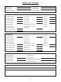
1
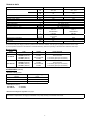
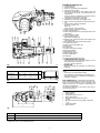
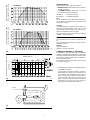
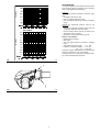
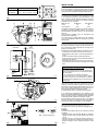
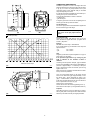
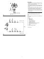
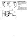
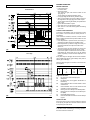
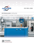
Installation, use and maintenance instructions
Gas Burners
RS 68/M LN - RS 120/M LN
Low-High-Low or Modulating Operation
C6505072 - 2915848 (3)
CONTENTS
TECHNICAL DATA . . . . . . . . . . . . . . . . . . . . . . . . . . . . . . .page
Burner models . . . . . . . . . . . . . . . . . . . . . . . . . . . . . . . . . . . . . . .
Accessories . . . . . . . . . . . . . . . . . . . . . . . . . . . . . . . . . . . . . . . . .
Burner description . . . . . . . . . . . . . . . . . . . . . . . . . . . . . . . . . . . .
Packaging - Weight . . . . . . . . . . . . . . . . . . . . . . . . . . . . . . . . . . .
Max. dimensions . . . . . . . . . . . . . . . . . . . . . . . . . . . . . . . . . . . . .
Standard equipment . . . . . . . . . . . . . . . . . . . . . . . . . . . . . . . . . . .
Firing rates . . . . . . . . . . . . . . . . . . . . . . . . . . . . . . . . . . . . . . . . . .
Minimum furnace dimensions. . . . . . . . . . . . . . . . . . . . . . . . . . . .
Commercial boilers. . . . . . . . . . . . . . . . . . . . . . . . . . . . . . . . . . . .
Gas pressure . . . . . . . . . . . . . . . . . . . . . . . . . . . . . . . . . . . . . . . .
WARNING
If you smell gas:
3
3
3
4
4
4
4
5
5
5
6
•
•
•
•
Do not touch any electrical items.
Open all windows.
Close all gas supply valves.
Contact your local gas authority immediately.
Do not store flammable or hazardous materials in the vicinity
of fuel burning appliances.
Improper installation, adjustment, alteration, service or maintenance can cause property damage, personal injury or
death. Refer to this manual for instructional or additional information. Consult a certified installer, service representative
or the gas supplier for further assistance.
INSTALLATION . . . . . . . . . . . . . . . . . . . . . . . . . . . . . . . . . . . . . . 7
Boiler mounting . . . . . . . . . . . . . . . . . . . . . . . . . . . . . . . . . . . . . . 7
Blast tube length . . . . . . . . . . . . . . . . . . . . . . . . . . . . . . . . . . . . . 7
Securing the burner to the boiler . . . . . . . . . . . . . . . . . . . . . . . . . 7
Ignition pilot adjustment . . . . . . . . . . . . . . . . . . . . . . . . . . . . . . . . 7
Combustion head adjustment. . . . . . . . . . . . . . . . . . . . . . . . . . . . 8
Gas piping . . . . . . . . . . . . . . . . . . . . . . . . . . . . . . . . . . . . . . . . . . 9
Adjustments before first firing. . . . . . . . . . . . . . . . . . . . . . . . . . . 10
Servomotor. . . . . . . . . . . . . . . . . . . . . . . . . . . . . . . . . . . . . . . . . .11
Burner starting . . . . . . . . . . . . . . . . . . . . . . . . . . . . . . . . . . . . . . 12
Maximum output. . . . . . . . . . . . . . . . . . . . . . . . . . . . . . . . . . . . . 12
Minimum output . . . . . . . . . . . . . . . . . . . . . . . . . . . . . . . . . . . . . 12
Intermediates outputs. . . . . . . . . . . . . . . . . . . . . . . . . . . . . . . . . 12
Air pressure switch . . . . . . . . . . . . . . . . . . . . . . . . . . . . . . . . . . . 13
High gas pressure switch . . . . . . . . . . . . . . . . . . . . . . . . . . . . . . 13
Low gas pressure switch . . . . . . . . . . . . . . . . . . . . . . . . . . . . . . 13
Flame present check . . . . . . . . . . . . . . . . . . . . . . . . . . . . . . . . . 13
Maintenance. . . . . . . . . . . . . . . . . . . . . . . . . . . . . . . . . . . . . . . . 14
Procedure to refer burner operating condition in high
altitude plants . . . . . . . . . . . . . . . . . . . . . . . . . . . . . . . . . . . . . . . 15
Siemens LFL control sequence of operations . . . . . . . . . . . . . . 16
Siemens LFL controltroubleshooting guide . . . . . . . . . . . . . . . . 17
Factory wiring diagram -burner mounted LFL . . . . . . . . . . . . . . 18
Field wiring diagram - burner mounted LFL . . . . . . . . . . . . . . . . 19
Factory wiring diagram - remote panel . . . . . . . . . . . . . . . . . . . . 20
Spare parts list . . . . . . . . . . . . . . . . . . . . . . . . . . . . . . . . . . . . . . 22
Burner start up report . . . . . . . . . . . . . . . . . . . . . . . . . . . . . . . . . 25
Burner shall be installed in accordance with manufacturers
requirements as outlined in this manual, local codes and authorities having jurisdiction.
2
TECHNICAL DATA
MODEL
MAX.
Output (1)
MIN.
Fuel
- Max. delivery
- Pressure at max. delivery (2)
RS 68/M LN
RS 120/M LN
MBtu/hr
kW
MBtu/hr
kW
1327 - 3258
389 - 955
570
167
2272 - 4924
666 - 1443
1136
333
SCFH
“WC
3258
4.60
Natural gas
Operation
Standard applications
Ambient temperature
Combustion air temperature
Main power supply (+/- 10%)
Fan motor
Low - high or modulating
Boilers: water, steam, thermal oil
32 - 104 (0 - 40 °C)
140 (60 °C)
208 - 230/460/575/3/60
°F
°F max
V/Ph/Hz
rpm
W - HP
V
A
V1 - V2
I1 - I2
W max
Ignition transformer
Electrical power consumption
Electrical protection
Noise levels (3)
4924
8.85
3400
1800 - 2.5
208-230/460/575
6.7/3.9/2.8
120 V - 1 x 8 kV
1.7 A - 20 mA
2200
3400
2200 - 3
208-230/460/575
8.8/5.1/3.7
2600
NEMA 1
dBA
75
77
(1) Reference conditions: Ambient temperature 68 °F (20 °C) - Barometric pressure 394 “WC - Altitude 329 ft a.s.l.
(2) Pressure at test point 16)(A)p.4, with zero pressure in the combustion chamber, with open gas ring 2)(B)p.8 at maximum burner output.
(3) Sound pressure measured in manufacturer’s combustion laboratory, with burner operating on test boiler and at maximum rated output.
Burner models
Model
Code
Voltage
Flame safeguard
RS 68/M LN
C9542000 (3897470)
C9542001 (3897475)
C9742000 (3897473)
C9742001 (3897473)
208-230/460/3/60
575/3/60
208-230/460/3/60
575/3/60
Burner mounted
Burner mounted
In an auxiliary panel (see Accessories)
In an auxiliary panel (see Accessories)
RS 120/M LN
C9543000 (3897670)
C9543001 (3897675)
C9743000 (3897673)
C9743001 (3897673)
208-230/460/3/60
575/3/60
208-230/460/3/60
575/3/60
Burner mounted
Burner mounted
In an auxiliary panel (see Accessories)
In an auxiliary panel (see Accessories)
ACCESSORIES (optional):
• Available auxiliary panels
•
Control panel code
Flame safeguard type
3010332
Fireye
3010336
Landis
3010338
Honeywell
Tubes kit (see page 5):
RS 68/M LN
cod. 3010247
RS 120/M LN
cod. 3010248
• Gas train according to UL regulation: see page 9.
Important:
The installer is responsible for the supply and installation of any safety device(s) not indicated in this manual.
3
BURNER DESCRIPTION (A)
1
2
3
4
5
6
7
8
9
10
11
12
13
14
15
16
17
18
19
20
21
22
23
24
25
26
(A)
Two types of burner failure may occur:
• FLAME SAFEGUARD LOCK-OUT:
if the flame relay 12)(A) pushbutton lights up, it indicates that the burner is in lock-out.
To reset, press the pushbutton.
• MOTOR TRIP:
release by pressing the pushbutton on thermal overload 8)(A).
D2792
inch
A (1)
B
C
RS 68/M LN
4627/32“ - 525/32“
291/8“
271/4“ 154
RS 120/M LN
4627/32“ - 525/32“
291/8“
271/4“ 167
Combustion head
Ignition electrode
Screw for combustion head adjustment
High gas pressure switch
Servomotor controlling the gas butterfly valve and
the air damper (by means of a variable profile cam
mechanism).
When the burner is stopped the air damper will be
completely closed to reduce heat loss
Plug-socket on ionisation proble cable
Extensions for slide bars 15) (supplied by kit)
Motor contactor and thermal overload with reset button
Power switch for different operations:
automatic - manual - off
Button for:
power increase - power reduction
Terminal strip for electrical connection
Pilot burner attachment
Flame safeguard with lock-out pilot light and lock-out
reset button
Flame inspection window
Low air pressure switch
(differential operating type)
Slide bars for opening the burner and inspecting the
combustion head
Gas pressure test point and head fixing screw
Air pressure test point
Flame sensor probe (flame rod)
Pilot burner
Air inlet to fan
Screws securing fan to sleeve
Gas input pipework
Gas butterfly valve
Boiler mounting flange
Flame stability disk
Air damper
PACKAGING - WEIGHT (B) - Approximate measurements
• The burners are shipped skid mounted
Outer dimensions of packaging are indicated in (B).
• The weight of the burner complete with packaging is
indicated in Table (B).
lbs
(B)
MAX. DIMENSIONS (C) - Approximate measurements
The maximum dimensions of the burner are given in (C).
Bear in mind that inspection of the combustion head
requires the burner to be opened by withdrawing the
rear part on the slide bars.
The maximum dimension of the burner, when open is
give by measurement I.
D36
STANDARD EQUIPMENT
1 - Gas train flange
1 - Flange gasket
4 - Flange fixing screws 3/8 W x 1”
1 - Burner head gasket
2 - Extensions 7)(A) for slide bars 15)(A)
(for kit)
4 - Screws to secure the burner flange to the boiler:
1/2 W
1 - Instruction booklet
1 - Spare parts list
D731
(C)
inch
RS 68/M
RS 120/M
A
B
C
D
E
F (1)
G
H
I (1)
L
M
N
O
129/32“ 815/32“ 2127/32“ 331/16“ 10“ - 153/8“ 77/16“ 1629/32“ 4511/16“ - 511/32“ 813/32“ 59/32“ 811/16“
2”
2125/32“ 135/16“ 815/32“ 2127/32“ 331/16“ 10“ - 153/8“ 77/16“ 1629/32“ 4511/16“ - 511/32“ 813/32“ 59/32“ 811/16“
2”
203/4“
(1) Blast tube: short - long (obtainable with kit)
4
CAM. COMB. / FEUERRAUM “WC
COMB. CHAMBER / CHAMB. COMB.
CAM. COMB. / FEUERRAUM “WC
COMB. CHAMBER / CHAMB. COMB.
FIRING RATES (A)
RS 68/M LN
During operation, burner output varies between:
• MAXIMUM OUTPUT, selected within area A (and B for
RS 120/M LN model),
• and MINIMUM OUTPUT, which must not be lower
than the minimum limit in the diagram.
RS 68/M LN
RS 120/M LN
Note
In order to utilize also area B (RS 120/M LN) it is necessary to perform the calibration of the combustion head
as explained on page 7.
Important
The FIRING RATE area values have been obtained considering an ambient temperature of 68 °F (20 °C), and
an atmospheric pressure of 394 “WC and with the combustion head adjusted as shown on page 8.
RS 120/M LN
Consult Procedure on page 15 to refer burner operating
condition in high altitude plants.
MINIMUM FURNACE DIMENSIONS (B)
D2793
The firing rates were set in relation to special test boilers.
Figure (B) indicates the diameter and length of the test
combustion chamber.
Example:
Output 2579 MBtu/hr:
diameter = 23.6 inch; length 6.6 ft
COMMERCIAL BOILERS (C) - IMPORTANT
(A)
The RS 68/M LN - RS 120/M LN burners are suitable for
operation on either flame-inversion boilers* or boilers with
combustion chambers featuring flow from the base (three
flue passes) on which the best results are obtained in
terms of low NOx emissions.
The maximum thickness of the boiler’s front door must
not exceed 8” (see fig. C).
Length (feet)
Diameter (inches)
Recommended furnace dimensions
= 570 MBtu/hr (167 kW)
= 1136 MBtu/hr (333 kW)
(B)
D2919
8” max
D1079
(C)
5
(*) For flame inversion boilers, a kit is available to reduce
CO emissions if required.
The kit includes 5 gas pipes, identical to the other 5
already fitted to the burner head. In standard conditions, the burner head is fitted with a second group of
pipes, with gas outlet in a different direction with respect to the others. With this Kit, the second group of
pipes is replaced, so that all the pipes are the same.
After fitting the kit, ensure they work correctly by
measuring the CO and flue gases emissions.
GAS PRESSURE
RS 68/M LN
∆p [“WC]
The adjacent diagrams show minimum pressure losses
along the gas supply line depending on the maximum
burner output operation with natural gas.
Column 1
Gas manifold pressure measured at test point 1)(B),
with:
• Combustion chamber at 0 “WC
• Burner operating at maximum output
• Gas ring 2)(B)p.8 adjusted as indicated in diagram
(C)p.8.
Calculate the approximate maximum output of the
burner thus:
- subtract the combustion chamber pressure from the
gas pressure measured at test point 1)(B).
- Find the nearest pressure value to your result in diagram for the burner in question.
- Read off the corresponding output on the left.
RS 120/M LN
∆p [“WC]
Example - RS 120/M LN:
• Maximum output operation
• Natural gas
• Gas ring 2)(B)p.8 adjust as indicated in diagram
(C)p.8
• Gas pressure at test point 1)(B)
= 5.11 “WC
• Pressure in combustion chamber = 1.18 “WC
5.11 - 1.18 = 3.93 “WC
A maximum output of 3030 MBtu/hr shown diagrams RS
120/M LN corresponds to 3.93 “WC pressure.
This value serves as a rough guide, the effective delivery must be measured at the gas meter.
(A)
D3182
(B)
D2390
6
INSTALLATION
inch
A
RS 68/M LN
RS 120/M LN
B
BOILER PLATE (A)
Drill the combustion chamber mounting plate as shown
in (A). The position of the threaded holes can be marked
using the burner head gasket supplied with the burner.
C
711/16“ 1013/16“ - 1225/32“ 1/2 W
711/16“ 1013/16“ - 1225/32“ 1/2 W
(A)
BLAST TUBE LENGTH (B)
The length of the blast tube must be selected according
to the indications provided by the manufacturer of the
boiler, it must be greater than the thickness of the boiler
door complete with its insulation. The range of lengths
available, (mm), is as follows:
D455
Blast tube 12)
• short
• long (with kit)
RS 68/M LN
10“
153/8“
RS 120/M LN
10“
153/8“
For boilers with front flue passes 15) or flame inversion
chambers, protective insulation material 13), must be
inserted between the boiler refractory 14) and the blast
tube 12).
This protective insulation must not compromise the
extraction of the blast tube.
For boilers having a water-cooled front, the insulation
13)-14) is not required unless it is required by the boiler
manufacturer.
(B)
D2794
Electrode
SECURING THE BURNER TO THE BOILER (B)
Before securing the burner to the boiler, check through
the blast tube opening to make sure that the flame sensor probe and the ignition electrode are correctly set in
position, as shown in (C).
Now detach the combustion head from the burner, fig. (B):
- Loosen the four screws 3) and remove the cover 1).
- Disengage the swivel joint 7) from the graduated sector 8)
- Remove the screws 2) from the two slide bars 5).
- Remove the two screws 4) and pull the burner back on
slide bars 5) by about 4”.
- Disconnect the wires from the flame rod and the electrode and then pull the burner completely off the slide
bars.
Probe
Ignition
pilot
(C)
D2796
1
2
COMBUSTION HEAD CALIBRATION
At this point check, for model RS 120/M LN, whether
the maximum delivery of the burner at high fire operation is contained in area A or in area B of the firing
rate. See page 5.
If it is in area A then no operation is required.
If, on the other hand, it is in area B, before starting
the burner remove the 4 circular sectors 1) (D) fastened behind the stabilizing disc by removing the 8
screws 2)(D).
Once this operation has been carried out (if it was
required), secure the flange 11)(B) to the boiler plate,
inserting the gasket 9)(B) supplied with the burner. Use
the 4 screws, also supplied with the unit, after first protecting the thread with an anti-locking product.
The seal between burner and boiler must be airtight.
(D)
D2382
If you noticed any irregularities in the positions of the
flame rod or ignition electrode during the check mentioned
above, remove screw 1)(E), extract the internal part 2)(E)
of the head and set up the two components correctly.
Do not attempt to turn the probe. Leave it in the position
shown in (C) since if it is located too close to the ignition
electrode the control box amplifier may be damaged.
IGNITION PILOT ADJUSTMENT
D2317
MB - Burner terminal strip
D1210
(E)
(F)
7
Place the pilot and electrode as shown in fig. (C).
The pilot works correctly at pressures ranging from 5 12” WC.
Important
To set the pilot without main burner operaton, proceed
as follows:
- Move the jumper from terminals "30-V11" to terminals
"30-VP", as given in fig. (F), this way the main valve is
cut out.
- With the burner in the manual position, hold the air
damper in the minimum position and make the setting.
- When the setting is correct, replace the jumper on “30V11”.
COMBUSTION HEAD SETTING
Installation operations are now at the stage where the
blast tube and sleeve are secured to the boiler as shown
in fig. (A). It is now a very simple matter to set up the
combustion head, as this depends solely on the MAX
output developed by the burner.
It is therefore essential to establish this value before proceeding to set up the combustion head.
There are two adjustments to make on the head:
• air delivery R1;
• gas delivery R2.
In diagram (C) find the notch to use for adjusting the air
and the gas, and then proceed as follows:
Air adjustment (A)
Turn screw 4)(A) until the notch identified is aligned with
the front surface 5)(A) of the flange.
IMPORTANT: In order to facilitate adjustment, loosen screw 6)(A), adjust and then
tighten.
D1256
(B)
(A)
Notches (Air=Gas)
Gas adjustment (B)
Loosen the 3 screws 1)(B) and turn ring 2) until the
notch identified is aligned with index 3). Tighten the 3
screws 1) fully down.
Example
RS 68/M LN, burner output = 1894 MBtu/hr
If we consult diagram (C) we find that for this output the
adjustments are:
• air:
R1 = notch 6;
• gas:
R2 = notch 2.
Note
Diagram (C) indicates an optimal regulation for a type of
boiler seen in fig. (B) page 5.
If the pressure of gas allows it, by closing ring nut
2)(B) a reduction of the formation of NOx is
obtained.
Maximum burner output
(C)
D2797
Continuing with the previous example, page 6 indicates
that for burner RS 68/M LN with output of 1894 MBtu/hr a
pressure of approximately 2” is necessary at test point
6)(A). If this pressure cannot be reached, open the ring
2)(B) to notch 4 or 5.
Make sure that the combustion characteristics are satisfactory and free of pulsations.
Once you have finished setting up the head, refit the
burner to the slide bars 3)(D) at approximately 4” from
the sleeve 4)(D) ” burner positioned as shown in fig.
(B)p. 7 ” insert the flame rod cable and the ignition electrode cable and then slide the burner up to the sleeve so
that it is positioned as shown in fig. (D).
Refit screws 2) on slide bars 3).
Secure the burner to the sleeve by tightening screw 1).
Reconnect the swivel joint 7) to the graduated sector 6).
(D)
D2376
8
Important
When fitting the burner on the two slide bars, it is advisable to gently draw out the high tension cable and flame
detection probe cable until they are slightly stretched.
GAS PIPING
• The main gas train must be connected to the gas
attachment 1)(A), using flange 2), gasket 3) and
screws 4) supplied with the burner.
• The gas train can enter the burner from the right or left
side, depending on which is the most convenient, see
fig. (A).
• The gas safety shut-off valves 8)-9)(A) must be as
close as possible to the burner to ensure gas reaches
the combustion head within the safety time range.
• The pilot gas train must be connected to the gas
attachment 5)(A) and can enter the burner from the
right or left side.
GAS TRAIN (B)
It must be type-approved according to required standards and is supplied separately from the burner.
(A)
D2393
TYPICAL UL SCHEMATIC GAS PIPING
Note
See the accompanying instructions for the adjustment of
the gas train.
KEY (A)
1 - Gas input pipe
2 - Manual valve
3 - Pressure regulator
4 - Low gas pressure switch
5 - 1st safety shut off valve
6 - 2nd safety shut off valve
7 - Standard issue burner with flange gasket
8 - Gas adjustment butterfly valve *
9 - Burner
10 - High gas pressure switch *
GAS PILOT LINE
* On the burner
MAIN GAS LINE
(B)
D2438
9
LOW GAS PRESSURE SWITCH
D2547
HIGH GAS PRESSURE SWITCH
AIR PRESSURE SWITCH
D2547
(A)
D2548
(B)
(C)
ADJUSTMENTS BEFORE FIRST FIRING
Adjustment of the combustion head, and air and gas
deliveries has been illustrated on page 8.
In addition, the following adjustments must also be
made:
- Open manual valves up-stream from the gas train.
- Adjust the minimum gas pressure switch to the start
of the scale (A).
- Adjust the maximum gas pressure switch to the end
of the scale (B).
- Adjust the air pressure switch to the zero position of
the scale (C).
- Purge the air from the gas line.
Fit a U-type manometer (D) to the gas pressure test
point on the sleeve.
The manometer readings are used to calculate the
MAX. burner power using the diagrams on page 6.
Before starting up the burner it is good practice to adjust
the gas train so that ignition takes place in conditions of
maximum safety, i.e. with gas delivery at the minimum.
D2377
(D)
10
SERVOMOTOR
The servomotor gives simultaneous regulation of the air
damper through the variable cam profile 4)(F) and the
gas butterfly valve.
It rotates by 130° in approx. 35 s.
The factory settings must not be changed for the first firing, just check that they comply with the details below.
To open the servomotor, remove the screws and pull the
cover outward, fig. (A).
CAMS AND TRIM POTENTIOMETERS FUNCTIONS
(A)
D2277
YES
Cam 1:
130°
Limits rotation towards maximum for gas.
NO
Cam 2:
0°
Limits rotation towards minimum, air damper closed on
stand by.
Cam 3:
20°
Limits gas ignition position.
Cams 4 - 5 - 6 - 7 - 8: not used
Don’t release the button indicated in this figure: the syncronization of the cams
made in factory would be
changed.
D2585
Figure above shows how the servomotor is released to manually check
(B) there is no binding though its motion.
Position jumpers
Trim potentiometer MAX
Limits maximum modulation.
It must be set near the stroke end (cam 1) to exploit as
far as possible the variable profile cam and maximum
opening of the gas butterfly valve.
Trim potentiometer MIN
Limits minimum modulation.
It must be set near the stroke end (cam 2) to exploit as
far as possible the variable profile cam.
Trim potentiometer POS
Limits an intermediate operating position between MAX
and MIN, supplying power to the "P" terminal in the servomotor (through an external command). This function
cuts out any external signals.
Note
Using the slide switch to select MAX or MIN, the servomotor goes into the position for the respective settings of
the MAX and MIN TRIM POTENTIOMETERS.
Trim potentiometers
Slide switch
When the settings are complete, place the slide switch
on OPE.
(C)
(D)
(E)
D2593
1 Servomotor
2 Graduated sector for gas
butterfly valve
3 Index for graduated sector 2
4 Adjustable profile cam
5 Adjustment screws for cam
starting profile
6 Adjustment fixing screws
7 Adjustment screws for cam
and profile
(F)
D2594
11
BURNER STARTING
Position jumpers
Close the control circuit, with the switch in fig. C) in the
AUTO position.
On firing (pilot burner and main valve) turn the switch (C)
to MAN and the switch 1)(E) in the AUT position.
Trim potentiometers
Slide switch
(A)
(B)
(C)
D2593
MAXIMUM OUTPUT
Using button (B), "increase output" until it locks out, app.
130° (cam 1).
Place the slide switch on MAX and set the relative MAX
trim potentiometer (setting must be very near to 130°) to
exploit as far as possible the variable profile cam 4)(D)
and have the gas butterfly valve on maximum opening,
graduated sector 2) on index 3) fig. (D).
The setting of the gas flow must be made on the gas train
regulator and, if necessary, on the gas valve.
The air setting must be made on the variable profile cam
4)(D) by turning the screws 5), after loosening the screws
6).
MINIMUM OUTPUT
With the slide switch on the OPE position, use button (B)
"decrease output" until it stops at app. 20° (cam 3).
Put the slide switch in the MIN position and set the modulation minimum using the relative MIN trim potentiometer.
Set the air using the variable profile cam 4)(D).
If a lower modulation minimum is required than the level
set on cam 3 of the servomotor (20°), decrease the cam
setting.
INTERMEDIATE OUTPUTS
With the switch (C) in the AUTO position, the slide switch
in the OPE position and the switch 1)(E) in the MAN position, move the button 2)(E) in various intermediate levels between maximum and minimum and set the variable
profile cam 4)(D) to achieve optimum combustion, by
turning the screws 5).
If possible, do not change the previously set maximum
and minimum levels.
Check the various setting levels with a combustion analysis.
1
2
3
4
5
6
7
Important
Make a progressive adjustment of the profile, without
sharp changes.
When the setting is complete, lock the cam profile using
screws 6)(D).
Turn the burner off, release the servomotor as shown in
fig. (B) page 11 and manually turn cam 4)(D) to check
there is no binding.
Servomotor
Graduated sector for gas butterfly valve
Index for graduated sector 2
Adjustable profile cam
Adjustment screws for cam starting profile
Adjustment fixing screws
Adjustment screws for cam and profile
Finally fix the adjustment by turning the screws 6)(D).
(D)
D2594
1
(E)
2
D791
12
AIR PRESSURE SWITCH (A)
AIR PRESSURE SWITCH
Adjust the air pressure switch after having performed all
other burner adjustments with the air pressure switch set
to the start of the scale (A).
With the burner operating at min. output, increase adjustment pressure by slowly turning the relative dial clockwise until the burner locks out.
Then turn the dial anti-clockwise by about 20% of the set
point and repeat burner starting to ensure it is correct.
If the burner locks out again, turn the dial anti-clockwise
a little bit more.
Attention:
As a rule, the air pressure switch must prevent the formation of CO.
To check this, insert a combustion analyser into the
chimney, slowly close the fan suction inlet (for example
with cardboard) and check that the burner locks out,
before the CO in the fumes exceeds 400 ppm.
D2548
(A)
HIGH GAS PRESSURE SWITCH
The air pressure switch may operate in "differential"
operation in two pipe system. If a negative pressure in
the combustion chamber during pre-purging prevents
the air pressure switch from switching, switching may be
obtained by fitting a second pipe between the air pressure switch and the suction inlet of the fan. In such a
manner the air pressure switch operates as differential
pressure switch.
HIGH GAS PRESSURE SWITCH (B)
Adjust the high gas pressure switch after having performed all other burner adjustments with the maximum
gas pressure switch set to the end of the scale (B).
With the burner operating at MAX output, reduce the
adjustment pressure by slowly turning the adjustment
dial anticlockwise until the burner locks out.
Then turn the dial clockwise by 0.8” WC and repeat
burner firing.
If the burner locks out again, turn the dial again clockwise by 0.4” WC.
D2547
(B)
LOW GAS PRESSURE SWITCH
LOW GAS PRESSURE SWITCH (C)
Adjust the low gas pressure switch after having performed all the other burner adjustments with the pressure
switch set at the start of the scale (C).
With the burner operating at MAX output, increase adjustment pressure by slowly turning the relative dial
clockwise until the burner locks out.
Then turn the dial anti-clockwise by 0.8” WC and repeat
burner starting to ensure it is uniform.
If the burner locks out again, turn the dial anti-clockwise
again by 0.4” WC.
D2547
FLAME PRESENT CHECK (D)
The burner is fitted with an ionisation (flame rod) system
which ensures that a flame is present. The minimum
current for reliable operation is 6 µA (see manufacturers
documentation). The burner provides a much higher current, so that controls are not normally required. However, if it is necessary to measure the ionisation current,
disconnect the plug-socket 6)(A)p.4 on the ionisation
probe cable and insert a direct current microamperometer with a base scale of 100 µA. Carefully check polarities.
(C)
DA
(D)
D1565
13
MAINTENANCE
FLAME INSPECTION WINDOW
Combustion
The optimum calibration of the burner requires an analysis of the flue gases. Significant differences with respect
to the previous measurements indicate the points where
more care should be exercised during maintenance.
Gas leaks
Make sure that there are no gas leaks on the pipework
between the gas meter and the burner.
Flame inspection window
Clean the flame inspection window (A).
Combustion head
Open the burner and make sure that all components of
the combustion head are in good condition, not
deformed by the high temperatures, free of impurities
from the surroundings and correctly positioned. If in
doubt, disassemble the elbow fitting 5)(B).
(A)
Servomotor
Disengage the cam 4)(D)p. 12 from the servomotor and
turn it backwards and forwards by hand to make sure it
moves freely.
D709
OPENING THE BURNER
Burner
Check for excess wear or loose screws in the mechanisms controlling the air damper and the gas butterfly
valve. Also make sure that the screws securing the electrical leads in the burner terminal strip are fully tightened.
Clean the outside of the burner, taking special care with
the swivel joints and cam.
Combustion
Adjust the burner if the combustion values found at the
beginning of the operation do not comply with the regulations in force, or do not correspond to good combustion. Record the new combustion values; they will be
useful for subsequent controls.
D2378
(B)
TO OPEN THE BURNER (B):
- Switch off the electrical power.
- Loosen screws 1) and withdraw cover 2).
- Disengage the swivel joint 7) from the graduated sector 8).
- Fit the two extensions onto the slide bars 4).
- Remove screws 3), and pull the burner back by about
4” on the slide bars 4). Disconnect the probe and
electrode leads and then pull the burner fully back.
Now extract the gas distributor 5) after having removed
the screw 6) and disconnecting the pilot gas line.
TO CLOSE THE BURNER (B):
- Push the burner until it is about 4” from the sleeve.
- Re-connect the leads and slide in the burner until it
comes to a stop.
- Refit screws 3), and pull the probe and electrode
leads gently out until they are slightly stretched.
- Re-couple the swivel joint 7) to the graduated sector
8).
- Remove the two extensions from the slide bars 4).
- Connect the pilot gas line.
14
PROCEDURE TO REFER BURNER OPERATING CONDITION IN HIGH ALTITUDE PLANTS
-
Find the corrected burner capacity for the plant’s altitude in chart 1 and the corrected pressure in chart 2.
Check in the firing rate graph of the burner (page 5), if the working point defined by the values above is within the range limits.
If not, higher burner size is needed.
Note
Charts are based only on altitude variation
(reference temperature = 68°F , 20°C)
To get the combined correction in case of different
air temperature, a compensation of 1000 ft each
20°F (305 m each 11°C) is applicable.
1
Rated Capacity
500
1000
1500
2000
2500
3000
3500
4000
4500
5000
5500
6000
6500
7000
7500
8000
8500
9000
9500
10000
Average barometric
Pressure (20°C)
Average barometric
Pressure (68°F)
2
Rated Pressure
0,50
1,00
1,50
2,00
2,50
3,00
3,50
4,00
4,50
5,00
5,50
6,00
6,50
7,00
7,50
8,00
8,50
9,00
9,50
10,00
Average barometric
Pressure (20°C)
Average barometric
Pressure (68°F)
Example
Rated capacity = 3000 MBtu/hr - Rated air pressure = 1.5”w.c.
Real altitude = 5000 ft - Real temperature = 108°F
∆ = 108°F - 68°F (reference temp.) = 40°F (equivalent 2000 ft variation)
Proceeding as descripted above and considering a “virtual altitude” of (5000 + 2000) ft:
- the corrected capacity is 3847 MBtu/hr;
Burner RS 120/M LN is OK
- the corrected burner air pressure is 1.92.
CORRECTED BURNER CAPACITY ACCORDING TO ALTITUDE
m. a.s.l.
ft a.s.l
0
0
494
987
1481
1974
2468
2962
3455
3949
4442
4936
5429
5923
6417
6910
7404
7897
8391
8885
9378
9872
100
328
500
1000
1500
2000
2500
3000
3500
4000
4500
5000
5500
6000
6500
7000
7500
8000
8500
9000
9500
10000
305
1000
512
1023
1535
2046
2558
3069
3581
4092
4604
5116
5627
6139
6650
7162
7673
8185
8697
9208
9720
10231
610
2000
530
1061
1591
2121
2652
3182
3712
4243
4773
5303
5834
6364
6894
7425
7955
8485
9016
9546
10076
10607
Altitude
915
3000
551
1101
1652
2202
2753
3303
3854
4404
4955
5505
6056
6606
7157
7708
8258
8809
9359
9910
10460
11011
1220
4000
571
1142
1713
2284
2855
3425
3996
4567
5138
5709
6280
6851
7422
7993
8564
9135
9705
10276
10847
11418
1525
5000
593
1186
1778
2371
2964
3557
4149
4742
5335
5928
6520
7113
7706
8299
8892
9484
10077
10670
11263
11855
1830
6000
616
1232
1848
2464
3079
3695
4311
4927
5543
6159
6775
7391
8006
8622
9238
9854
10470
11086
11702
12318
2135
7000
641
1282
1924
2565
3206
3847
4488
5130
5771
6412
7053
7694
8335
8977
9618
10259
10900
11541
12183
12824
2440
8000
669
1337
2006
2675
3343
4012
4680
5349
6018
6686
7355
8024
8692
9361
10029
10698
11367
12035
12704
13373
mbar
1013
1000
977,4
942,8
908,2
875,8
843,5
811,85
779,8
747,8
"w.c.
399
394
385
371
358
345
332
320
307
294
CORRECTED BURNER AIR PRESSURE ACCORDING TO ALTITUDE
m. a.s.l.
ft a.s.l
0
0
0,49
0,99
1,48
1,97
2,47
2,96
3,46
3,95
4,44
4,94
5,43
5,92
6,42
6,91
7,40
7,90
8,39
8,88
9,38
9,87
100
328
0,50
1,00
1,50
2,00
2,50
3,00
3,50
4,00
4,50
5,00
5,50
6,00
6,50
7,00
7,50
8,00
8,50
9,00
9,50
10,00
305
1000
0,51
1,02
1,53
2,05
2,56
3,07
3,58
4,09
4,60
5,12
5,63
6,14
6,65
7,16
7,67
8,18
8,70
9,21
9,72
10,23
610
2000
0,53
1,06
1,59
2,12
2,65
3,18
3,71
4,24
4,77
5,30
5,83
6,36
6,89
7,42
7,96
8,49
9,02
9,55
10,08
10,61
Altitude
915
3000
0,55
1,10
1,65
2,20
2,75
3,30
3,85
4,40
4,95
5,51
6,06
6,61
7,16
7,71
8,26
8,81
9,36
9,91
10,46
11,01
1220
4000
0,57
1,14
1,71
2,28
2,85
3,43
4,00
4,57
5,14
5,71
6,28
6,85
7,42
7,99
8,56
9,13
9,71
10,28
10,85
11,42
1525
5000
0,59
1,19
1,78
2,37
2,96
3,56
4,15
4,74
5,33
5,93
6,52
7,11
7,71
8,30
8,89
9,48
10,08
10,67
11,26
11,86
1830
6000
0,62
1,23
1,85
2,46
3,08
3,70
4,31
4,93
5,54
6,16
6,77
7,39
8,01
8,62
9,24
9,85
10,47
11,09
11,70
12,32
2135
7000
0,64
1,28
1,92
2,56
3,21
3,85
4,49
5,13
5,77
6,41
7,05
7,69
8,34
8,98
9,62
10,26
10,90
11,54
12,18
12,82
2440
8000
0,67
1,34
2,01
2,67
3,34
4,01
4,68
5,35
6,02
6,69
7,35
8,02
8,69
9,36
10,03
10,70
11,37
12,04
12,70
13,37
mbar
1013
1000
977,4
942,8
908,2
875,8
843,5
811,85
779,8
747,8
"w.c.
399
394
385
371
358
345
332
320
307
294
Reference conditions (Charts 1-2): Ambient temperature 68 °F (20 °C) - Barometric pressure 394” WC (1000 mbar) - Altitude 328 ft a.s.l. (100 m a.s.l.)
15
BURNER OPERATION
LFL 1.335 Series 01
BURNER STARTING
• Load control close.
Fan motor starts.
• Servomotor starts:
130° rotation to right, until contact is made on cam
1)(A) page 12.
The air damper is positioned to MAX. output.
• Pre-purge stage with air delivery at MAX. output.
• After pre-purge stage, servomotor rotates to left up to
the angle set on cam 3)(A) page 12 for MIN. output.
• The air damper and the gas butterfly are positioned to
MIN. output.
• Ignition electrode strikes a spark.
• Pilot valve opens. The pilot flame is ignited.
• After about 12 s the main flame ignites and starting
cycle ends.
Full Modulation
(A)
D2273
Low - High
STEADY STATE OPERATION
At the end of the starting cycle, the servomotor control
then passes to the load control for boiler pressure or
temperature.
(The control box continues, however, to check that the
flame is present and that the air pressure switch is in the
correct position.)
• If the temperature or pressure is low, the burner progressively increases its output to the MAX. value.
• If the temperature or pressure is high, the burner progressively decreases its output to the MIN. value.
And so on.
• The burner locks out when demand for heat is less
than the heat supplied by the burner at min. output.
Load control opens. The servomotor returns to the 0°
angle limited by contact with cam 2. The air damper
closes completely to reduce thermal dispersion to a
minimum.
Every time output is changed, the servomotor automatically modifies gas delivery (gas butterfly valve) and air
delivery (fan air damper).
Switching times are given in seconds, in the burner startup sequence.
LFL 1.335 Series 01
t1
t2
t3
t4
(B)
D2274
30
2
4
20
t5
t6
t7
t8
optional
optional
12
4
Legend for the times
t1
Pre-purge time with air damper open
t2
Safety time
t3
Pre-ignition time, short (ignition transformer on
terminal 16)
t4
Interval between start of t2 and release of valve
at terminal 19
t5
Interval between end of t4 and release of load
controller or valve at terminal 20
t5
Running time of air damper into OPEN position
t6
Running time of air damper into low-flame position (MIN)
t7
Permissible after-burn time
t8
Interval until OPEN command for the air damper
is given
FIRING FAILURE
If the burner does not fire, it locks out within 2.5 seconds
from opening the pilot valve and then within 5 seconds
from opening the main valves.
BURNER FLAME GOES OUT DURING OPERATION
If the flame should accidentally go out during operation,
the burner will lock out within 1s.
16
BURNER FAULTS
Control program under fault
conditions and lock-out
indication
LFL 1.335 Series 01
In case of any disturbance, the sequence mechanism stops and with it the lock-out indicator. The symbol
above the reading mark of the indicator gives the type of disturbance:
No start, e.g. because one contact is not closed. Lock-out during or after control program sequence
due to extraneous light (e.g. non-extinguished flames, leaking fuel valves, defects in the flame
supervision circuit, etc.)
Interruption of startup sequence, because the OPEN signal has not been delivered to terminal 8
by limit switch “a”. Terminals 6, 7 and 14 remain under voltage until the fault has been corrected!
P
Lockout, because there is no air pressure indication at the beginning of air pressure control.
Every air pressure failure after this moment in time leads to lock-out, too!
Lock-out due to a fault in the flame supervision circuit.
Interruption of startup sequence, because the position signal for the low-flame position has not
been delivered to terminal 8 by auxiliary switch “m”. Terminals 6, 7 and 14 remain under voltage
until the fault has been corrected!
1
Lock-out, because no flame signal is present after completion of the (1st) safety time.
2
Lock-out, because no flame signal has been received on completion of the 2nd safety time (flame
signal of the main flame with interrupted pilot burners).
Lock-out, because the flame signal has been lost during burner operation.
If lock-out occurs at any other moment in time between the start and the pre-ignition which is not marked by
a symbol, this is usually caused by a premature, i.e. faulty flame signal, e.g. caused by a self-igniting UV
tube.
17
Factory Wiring Diagram
RS 68/M LN - RS 120/M LN
with burner mounted Siemens LFL control
D2332
(A)
Field Wiring Diagram
RS 68/M LN - RS 120/M LN
with burner mounted Siemens LFL control
D2333
Motor Connection
RS 68/M LN
RS 120/M LN
208 208 460 V 575 V
460 V 575 V
230 V
230 V
F
A
T15
T10
T6
T15
T10
T10
S
AWG
14
14
14
14
14
14
D3686
Wire size when not indicated: AWG18.
(B)
18
Factory Wiring Diagram
RS 68/M LN - RS 120/M LN
with burner mounted Siemens LFL control
Continuous fan operation
Change the wire connection from terminal 6 to terminal 1, move the jumper from terminals 12-13 to terminals 4-12 and
remove the wire from terminal 13 of control box as indicated below.
D2878
(C)
LAYOUT (A) - (B) - (C)
Burner RS 68/M LN - RS 120/M LN
PG
PGM
PS
RT
SM
SO
SP
TA
TB
Y0
Y10
Y11
Y13
Key to Layouts
CMV
- Motor contactor
DA
- LFL Control box
HL
- High limit
H1
- Remote lock-out signal
H2
- Burner on signal
H4
- Power on signal
H5
- Permission ok
IN
- Burner manual stop switch
MB
- Burner terminal strip
MV
- Fan motor
OC
- Operating control
OC2
- High-low control
PA
- Air pressure switch
-
Min. gas pressure switch
High gas pressure switch
Remote lock-out reset
Thermal overload
Servomotor
Ionisation probe (flame rod)
Plug-socket
Ignition transformer
Burner ground
Pilot adjustment valve
Adjustment valve
Safety valve
Pilot valve (safety)
NOTES
• For electrical connection use flexible cables according to local Regulations.
• The setting of the thermal overload must be according to the total burner amperage draw.
• The RS 68/M LN - RS 120/M LN burners leave the factory preset for:
- 208-230 V power supply: only in this case, if 460 V power supply is required, change the fan motor connection from delta to star and change the
setting of the thermal overload as well;
- or 575 V power supply;
depending on the burner model (see page 3).
• The RS 68/M LN - RS 120/M LN burners have been type-approved for intermittent operation. This means they should compulsorily be stopped at
least once every 24 hours to enable the control box to check its own efficiency at start-up. Burner halts are normally provided for automatically by
the boiler load control system.
If this is not the case, a time switch should be fitted in series to IN to provide for burner shut-down at least once every 24 hours.
Important note
When installing for the first time and after any maintenance work, make sure the gas valves are connected properly to the orange terminals
before proceeding to ignite the burner. Insert auxiliary lamps or check, with the aid of a tester, that power is not being supplied to the valves
during standby or pre-purging. Burner ignition with the gas valves open during pre-purging may cause an explosive condition.
19
20
Factory Wiring Diagram
RS 68/M LN - RS 120/M LN with auxiliary control panel
Layout (A)
LAYOUT (A) page 20
Burner RS 68/M LN - RS 120/M LN
The flame safeguard is in an auxiliary panel.
See the internal electrical systems of the auxiliary panel in order to have the complete wiring diagram.
Key to layout
B4
- Ionisation probe (flame rod)
F1
- Fan motor thermal overload
K1
- Fan motor contactor
MB
- Burner terminal strip
MV
- Fan motor
S10
- Air pressure switch
S12
- High gas pressure switch
SM
- Servomotor
T1
- Ignition transformer
TB
- Burner ground (earth) connection
XQ1
- Plug
XQ2
- Plug
XQ3
- Plug
XQ4
- Plug
21
22
20
72
19
12
SPARE PARTS LIST
23
11
13
17
18
22
15
16
21
25
5
4
7
8
37
36
31
9
35
3
2
9
8
7
6
5
4
3
2
1
0
71
10
34
26
44
6
69
32
1
68
33
54
53
52
51
50
38
30
70
27
55
40
24
48
57
46
65
67
57
61
58
47
60
43
57
42
56
41
29
28
66
57
45
39
49
64
14
59
63
62
23
1
2
3
4
4
5
6
7
8
9
9
10
11
12
13
14
15
15
15
15
16
17
18
18
18
18
19
20
21
22
23
24
25
26
27
27
28
28
29
29
30
31
32
33
34
3003948
3003949
3003952
3012403
3012940
3003763
3007265
3012974
3012948
3013127
3013205
3012955
3012343
3007627
3012080
3012359
3012936
3012937
3013124
3013125
3012956
3012934
3012942
3012943
3013060
3013061
3012957
3012944
3012012
3012958
3012959
3012346
3013081
3012176
3012924
3012925
3013082
3013083
3013084
3013085
3012035
3013086
3013088
3012412
3012014
•
•
•
•
•
•
•
•
•
•
•
•
•
•
•
•
•
•
C9742000 (3897473) *
C9743000 (3787673) *
C9543000 (3787670)
•
• • • •
• • • •
• • • •
•
• • •
• • • •
• • • •
• • • •
• • • •
• •
•
•
• •
• • • •
• • • •
• •
• • • •
C9543001 (3787675)
•
• • • • • • •
• • • • • • •
•
•
•
•
•
•
•
• • • • • • •
• • • • • • •
• • • • • • •
• • • • • • •
• • • • • • •
• • • • • • •
• • • • • • •
• • • • • • •
• • • •
• • •
• • • •
• • •
• • • •
• • •
• • • • • • •
• • • • • • •
• • • • • • •
• • • • • • •
• • • • • • •
•
•
•
• •
• •
•
• •
•
•
•
•
C9542000 (3897470)
•
•
•
•
•
•
C9542001 (3897475)
•
•
•
•
C9742001 (3897473) *
* = Versione minima - Minimum Version
C5830008
N. CODE
•
•
•
•
•
•
•
•
•
•
•
•
•
•
•
•
•
•
•
•
•
•
•
•
•
•
•
•
•
•
•
C9743001 (3787673) *
AIR DAMPER ASSEMBLY
GRID
SOUND DAMPING
FAN
FAN
INSPECTION WINDOW
U BOLT
PILOT TUBE
AIR PRESSURE SWITCH
BASE PLATE
BASE PLATE
CONTROL BOX LFL 1.335
SUPPORT
MEMBRAN
SWITCH
LEVER
OVERLOAD+CONTACTOR 208-230/460V
OVERLOAD+CONTACTOR 208-230/460V
OVERLOAD+CONTACTOR 575V
OVERLOAD+CONTACTOR 575V
TRANSFORMER
COVER
MOTOR 208-230/460V
MOTOR 208-230/460V
MOTOR 575V
MOTOR 575V
ANCHOR PLATE
SERVOMOTOR
HALF-SHELL
PROBE LEAD
H.T. LEAD
ANCHOR PLATE
ELECTRODE
PROBE
TUBE
TUBE
SCOOP
SCOOP
GAS HEAD
GAS HEAD
INTERIOR TUBE
SUPPORT
EXTERIOR TUBE
ELBOW
FERRULE
DESCRIPTION
GRUPPO SERRANDA
PROTEZIONE
FONOASSORBENTE
GIRANTE
GIRANTE
VISORE
CAVALLOTTO
TUBO PILOTA
PRESSOSTATO ARIA
MENSOLA
MENSOLA
APPARECCHIATURA LFL 1.335
SUPPORTO
MEMBRANA
INTERRUTTORE
LEVA
RELE' + CONTATTORE 208-230/460V
RELE' + CONTATTORE 208-230/460V
RELE' + CONTATTORE 575V
RELE' + CONTATTORE 575V
TRASFORMATORE
COFANO
MOTORE 208-230/460V
MOTORE 208-230/460V
MOTORE 575V
MOTORE 575V
PIASTRA
SERVOMOTORE
GUSCIO
COLLEGAMENTO PER SONDA
COLLEGAMENTO PER ELETTRODO
PIASTRA
ELETTRODO
SONDA
TUBETTO
TUBETTO
TAZZA
TAZZA
DISTRIBUTORE
DISTRIBUTORE
TUBO INTERNO
SUPPORTO
TUBO ESTERNO
GOMITO
GHIERA
DESCRIZIONE
Burner serial number
Matricola bruciatore
24
35
36
37
38
39
40
41
42
43
44
45
46
46
47
48
49
50
51
52
53
54
55
56
57
58
59
60
61
62
63
64
65
66
67
68
69
70
71
72
3012013
3003481
3003891
3012969
3012358
3012049
3012618
3012413
3012414
3003409
3012415
3012416
3012417
3003322
3013089
3006097
3007166
3005482
3012971
3003996
3012348
3012972
3012350
3006098
3012059
3003841
3012351
3012352
3012353
3012354
3012355
3012356
3012060
3012357
3013055
3003220
3013087
3013010
3013229
C9542001 (3897475)
•
•
•
•
•
•
•
•
•
•
•
•
•
•
•
•
•
•
•
•
•
•
•
•
•
•
•
•
•
•
•
•
•
•
•
•
•
C9542000 (3897470)
•
•
•
•
•
•
•
•
•
•
•
•
•
•
•
•
•
•
•
•
•
•
•
•
•
•
•
•
•
•
•
•
•
•
•
•
•
C9742000 (3897473) *
•
•
•
•
•
•
•
•
•
•
•
•
•
•
•
•
•
•
•
•
•
•
•
•
•
•
•
•
•
•
•
•
•
•
•
•
• •
•
•
•
•
•
•
•
•
•
•
•
•
•
•
•
•
•
•
•
•
•
•
•
•
•
•
•
•
•
•
•
•
•
•
•
•
C9742001 (3897473) *
* = Versione minima - Minimum Version
C5360002
C5332011
N. CODE
•
•
•
•
•
•
•
•
•
•
•
•
•
•
•
•
•
•
•
•
•
•
•
•
•
•
•
•
•
•
•
•
•
•
•
•
•
•
•
•
•
•
•
•
•
•
•
•
•
•
•
•
C9543000 (3787670)
•
•
•
•
•
•
•
•
•
•
•
C9543001 (3787675)
•
•
•
•
•
•
•
•
•
•
•
C9743000 (3787673) *
•
•
•
•
•
•
•
•
•
•
•
•
•
•
•
•
•
•
•
•
•
•
•
•
•
•
•
•
•
•
•
•
•
•
•
•
• •
•
•
•
•
•
•
•
•
•
•
•
•
•
•
•
•
•
•
•
•
•
•
•
•
•
•
•
•
•
•
•
•
•
•
•
•
C9743001 (3787673) *
BAR
SCREW
CONNECTOR
GAS PRESSURE SWITCH
CAM ASSEMBLY
SCREW
CONTROL DEVICE
FRONT PIECE
SQUARE
U BOLT
END CONE
SHUTTER
SHUTTER
CONNECTOR
MANIFOLD
FLAT SPRING
SEAL
SEAL
FLANGE AND ELBOW
PLUG
AIR INTAKE
SHAFT
LEVER
PIN JOINT
BUTTERFLY VALVE SHAFT
BEARING
TIE ROD
BAR
BAR
LEVER
GRADUATE SECTOR
SPRING
TIE ROD
BEARING
TUBE
CONNECTOR
SUPPORT
CONTROL BOX BASE
PLUG
DESCRIPTION
PERNO
VITE
RACCORDO
PRESSOSTATO GAS
CAMMA COMPLETA
VITE
GRUPPO REGOLATORE
FRONTONE
SQUADRETTA
CAVALLOTTO
IMBUTO FIAMMA
OTTURATORE
OTTURATORE
RACCORDO
MANICOTTO
MOLLA PER CAMMA
GUARNIZIONE
GUARNIZIONE
FLANGIA E GOMITO
TAPPO
BOCCA D'ASPIRAZIONE
ALBERO
LEVA
SNODO SFERICO
ALBERO MANICOTTO
CUSCINETTO
TIRANTE
PERNO
PERNO
LEVA
QUADRANTE
MOLLA
TIRANTE
CUSCINETTO
TUBO
RACCORDO
SUPPORTO
ZOCCOLO
SPINA
DESCRIZIONE
Burner serial number
Matricola bruciatore
BURNER START UP REPORT
Model number:
Serial number:
Project name:
Start-up date:
Installing contractor:
Phone number:
GAS OPERATION
Gas Supply Pressure:
CO2: Low Fire
High Fire
Main Power Supply:
O2: Low Fire
High Fire
Control Power Supply:
CO: Low Fire
High Fire
Burner Firing Rate:
NOX: Low Fire
High Fire
Manifold Pressure:
Net Stack Temp - Low Fire:
High Fire:
Pilot Flame Signal:
Comb. Efficiency - Low Fire:
High Fire:
Low Fire Flame Signal:
Overfire Draft:
High Fire Flame Signal:
OIL OPERATION
Oil supply pressure:
CO2: Low Fire
High Fire
Oil suction pressure:
O2: Low Fire
High Fire
Control Power Supply:
CO: Low Fire
High Fire
Burner Firing Rate:
NOX: Low Fire
High Fire
Low Fire Flame Signal:
Net Stack Temp - Low Fire:
High Fire:
High Fire Flame Signal:
Comb. Efficiency - Low Fire:
High Fire:
Low Fire Nozzle Size:
Overfire Draft:
High Fire Nozzle Size:
Smoke number:
CONTROL SETTINGS
Operating Setpoint:
Low Oil Pressure:
High Limit Setpoint:
High Oil Pressure:
Low Gas Pressure:
Flame Safeguard Model Number:
High Gas Pressure:
Modulating Signal Type:
NOTES
25
RIELLO S.p.A.
Via degli Alpini 1
I - 37045 Legnago (VR)
Tel.: +39.0442.630111 Fax: +39.0442.630375
http:// www.rielloburners.com
RIELLO BURNERS NORTH AMERICA
1-800-4-RIELLO
35 Pond Park Road
Hingham, Massachusetts,
1-800-474-3556
U.S.A. 02043
2165 Meadowpine Blvd.
Mississauga, Ontario,
Canada L5N 6H6
http://www.riello-burners.com
Subject to modifications