1
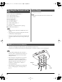
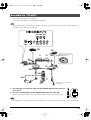
TD-6KX_e 1 ページ 2006年10月25日 水曜日 午後5時8分
Owner’s Manual
Thank you, and congratulations on your choice of the Roland Drum System TD-6KX.
201a
Before using this unit, carefully read the sections entitled: “USING THE UNIT
SAFELY” and “IMPORTANT NOTES” (p. 2, p. 3). These sections provide important
information concerning the proper operation of the unit. Additionally, in order to feel
assured that you have gained a good grasp of every feature provided by your new
unit, Owner’s manual should be read in its entirety. The manual should be saved
and kept on hand as a convenient reference.
202
Copyright © 2006 ROLAND CORPORATION
All rights reserved. No part of this publication may be reproduced in
any form without the written permission of ROLAND CORPORATION.
TD-6KX_e 2 ページ 2006年10月25日 水曜日 午後5時8分
USING THE UNIT SAFELY
The
symbol alerts the user to important instructions
or warnings.The specific meaning of the symbol is
determined by the design contained within the
triangle. In the case of the symbol at left, it is used for
general cautions, warnings, or alerts to danger.
Used for instructions intended to alert
the user to the risk of death or severe
injury should the unit be used
improperly.
Used for instructions intended to alert
the user to the risk of injury or material
damage should the unit be used
improperly.
* Material damage refers
other adverse effects
respect to the home
furnishings, as well
animals or pets.
to damage or
caused with
and all its
to domestic
001
•
The
symbol alerts the user to items that must never
be carried out (are forbidden). The specific thing that
must not be done is indicated by the design contained
within the circle. In the case of the symbol at left, it
means that the unit must never be disassembled.
The ● symbol alerts the user to things that must be
carried out. The specific thing that must be done is
indicated by the design contained within the circle. In
the case of the symbol at left, it means that the powercord plug must be unplugged from the outlet.
006
Before using this unit, make sure to read the
instructions below, and the Owner’s Manual.
•
................................................................................................
002b
•
Do not open or perform any internal modifications
on the unit. (The only exception would be where
this manual provides specific instructions which
should be followed in order to put in place user-installable
options; see p. 13.)
................................................................................................
................................................................................................
011
•
003
•
Do not attempt to repair the unit, or replace parts
within it (except when this manual provides
specific instructions directing you to do so). Refer
all servicing to your retailer, the nearest Roland
Service Center, or an authorized Roland
distributor, as listed on the “Information” page.
................................................................................................
•
................................................................................................
In households with small children, an adult should
provide supervision until the child is capable of
following all the rules essential for the safe
operation of the unit.
Never use or store the unit in places that are:
................................................................................................
• Subject to temperature extremes (e.g.,
direct sunlight in an enclosed vehicle, near
a heating duct, on top of heat-generating
equipment); or are
014
• Damp (e.g., baths, washrooms, on wet
floors); or are
•
• Exposed to rain; or are
• Dusty; or are
• Subject to high levels of vibration.
................................................................................................
005
This unit should be used only with a stand (MDS
series) that is recommended by Roland.
................................................................................................
Do not drop it!
104
•
• Humid; or are
•
Do not allow any objects (e.g., flammable material,
coins, pins); or liquids of any kind (water, soft
drinks, etc.) to penetrate the unit.
013
004
•
When using the unit with a stand (MDS series)
recommended by Roland, the stand (MDS series)
must be carefully placed so it is level and sure to
remain stable. If not using a rack or stand, you still
need to make sure that any location you choose for
placing the unit provides a level surface that will
properly support the unit, and keep it from wobbling.
Try to prevent cords and cables from becoming
entangled. Also, all cords and cables should be
placed so they are out of the reach of children.
................................................................................................
106
•
Never climb on top of, nor place heavy objects on
the unit.
................................................................................................
118a
•
Should you remove nuts, washers, screws, anchor
bolts, etc., keep them in a safe place out of
children’s reach, so there is no chance of them
being swallowed accidentally.
................................................................................................
2
TD-6KX_e 3 ページ 2006年10月25日 水曜日 午後5時8分
562
IMPORTANT NOTES
291a
In addition to the items listed under “USING THE UNIT
SAFELY” on page 2, please read and observe the
following:
•
Some connection cables contain resistors. Do not use
cables that incorporate resistors for connecting to this unit.
The use of such cables can cause the sound level to be
extremely low, or impossible to hear. For information on
cable specifications, contact the manufacturer of the cable.
Placement
354a
•
Do not expose the unit to direct sunlight, place it near
devices that radiate heat, leave it inside an enclosed
vehicle, or otherwise subject it to temperature extremes.
Excessive heat can deform or discolor the unit.
356
•
Do not allow rubber, vinyl, or similar materials to remain
on the unit for long periods of time. Such objects can
discolor or otherwise harmfully affect the finish.
Maintenance
401a
•
For everyday cleaning wipe the unit with a soft, dry cloth
or one that has been slightly dampened with water. To
remove stubborn dirt, use a cloth impregnated with a
mild, non-abrasive detergent. Afterwards, be sure to wipe
the unit thoroughly with a soft, dry cloth.
402
•
Never use benzine, thinners, alcohol or solvents of any
kind, to avoid the possibility of discoloration and/or
deformation.
Additional Precautions
553
•
Use a reasonable amount of care when using the unit’s
buttons, sliders, or other controls; and when using its jacks
and connectors. Rough handling can lead to malfunctions.
556
•
When connecting / disconnecting all cables, grasp the
connector itself—never pull on the cable. This way you
will avoid causing shorts, or damage to the cable’s
internal elements.
558a
•
To avoid disturbing your neighbors, try to keep the unit’s
volume at reasonable levels. You may prefer to use
headphones, so you do not need to be concerned about
those around you (especially when it is late at night).
558d
•
This instrument is designed to minimize the extraneous
sounds produced when it’s played. However, since sound
vibrations can be transmitted through floors and walls to a
greater degree than expected, take care not to allow these
sounds to become a nuisance to neighbors, especially
when performing at night and when using headphones.
559b
•
When you need to transport the unit, pack it in shockabsorbent material. Transporting the unit without doing
so can cause it to become scratched or damaged, and
could lead to malfunction.
3
TD-6KX_e 4 ページ 2006年10月25日 水曜日 午後5時8分
Checking the Contents of the
Box
Drum Stand
Assemble the Drum Stand.
❑ TD-6V (Percussion Sound Module) x 1
❑ KD-8 (Kick Trigger Pad) x 1
About the Stand, refer to the owner’s manual for the
❑ FD-8 (Hi-Hat Control Pedal) x 1
stand.
❑ PD-105 (Snare Pad) x 1
❑ PD-85 (Tom Pad) x 3
❑ CY-5 (Hi-Hat Cymbal) x 1
❑ CY-8 (Crash Cymbal) x 1
❑ CY-12R/C (Ride Cymbal) x 1
❑ Connection Cables
❑ Tuning Key x 1 (included in the FD-8 package)
■ TD-6KX Owner’s Manual x 1
• The TD-6V Owner’s Manual is included in the TD-6V
package.
• This package does not include a kick pedal. Use with a
commercially available kick pedal.
962a
* In the interest of product improvement, the specifications and/
or appearance of this unit are subject to change without prior
notice.
TD-6V
(Percussion Sound Module)
Attach the mounting plate (included with the optional drum stand) to the TD-6V.
Using the screws attached to the bottom panel, attach the plate so the unit is oriented as shown in the diagram.
fig.TD-6V.e
• To attach the mounting plate, remove the four 8
mm screws (M5 x 8) from the bottom of the TD-6V
and use them. Use of other screws may result in
damage to the unit.
• When turning the unit upside-down, get a bunch
of newspapers or magazines, and place them
under the four corners or at both ends to prevent
damage to the buttons and controls. Also, you
should try to orient the unit so no buttons or
controls get damaged.
• When turning the unit upside-down, handle with
care to avoid dropping it, or allowing it to fall or
tip over.
4
Narrow
Wide
TD-6KX_e 5 ページ 2006年10月25日 水曜日 午後5時8分
.
USING THE UNIT SAFELY
Assemble the “TD-6KX”
921
Using the provided cables, connect the pads.
Connect the L-shaped plugs of the included cables to the pads.
To prevent malfunction and/or damage to speakers or other devices, always turn down the volume, and turn off the power
on all devices before making any connections.
fig.Setting1.e
HH SNR KIK
RD
HHC
CR1 T3 T2 T1
CR1
RD
CY-8
CY-12R/C
T1
HH
T2
PD-85
Make the connection to the
BOW/EDGE output.
PD-85
CY-5
TD-6V
PD-105
T3
PD-85
SNR
KIK
KD-8
HHC
FD-8
* This package does not include
a kick pedal.
fig.Label
1. Insert the plugs of connecting cables into the TRIGGER INPUTS jacks on the rear
of the TD-6V.
2. Insert the L-sharped plugs into the TRIGGER OUTPUTS jacks of the pads.
SNR
* When you connect the cables, please refer to the marking label that is attached on both edge of the cables.
• Rim triggering is not supported on PD-85 when connected to any of the tom inputs on the TD-6V Percussion Sound Module.
5
TD-6KX_e 6 ページ 2006年10月25日 水曜日 午後5時8分
3. Use a tuning key supplied with the FD-8 to
tighten the screws removed in Step 1 so that
the stand is firmly secured.
USING THE UNIT SAFELY
KD-8
(Kick)
fig.KD-Assy03
fig.KD-8.e
Output Jack
Head
Stand
Anchor Bolt
Foot Plate
Making the Settings
4. Attach the kick pedal.
Position the beater so that it strikes the center of the head,
then secure the kick pedal and KD-8 firmly in place.
fig.KD-Assy04.e
1. Remove the screws attached to the reverse side
of the KD-8’s trigger.
Beater
fig.KD-Assy01
Install the kick pedal securely.
Adjusting the Foot Plate Height
2. Pull out the stand in the direction indicated by
the arrow until it is fully extended.
Depending on your kick pedal, it can be unstable when you
attach it to the KD-8. Be sure to adjust the foot plate height so
that the entire bottom surface of the pedal is attached to the
floor.
fig.KD-Assy02
fig.KD-Assy05.e
Beater
Commercially Available Kick Pedal
* Adjust the height so that the entire pedal comes
into contact with the floor.
6
TD-6KX_e 7 ページ 2006年10月25日 水曜日 午後5時8分
1. Loosen the stand’s anchor bolts and remove
the foot plate.
fig.KD-Assy06
Adjusting the Anchor
Bolts
USING
THE UNIT SAFELY
When using the kick pedal on a drum mat or similar surface,
adjust the anchor bolts so their tips protrude from the plate
and secure the pedal in place; this will make it easier to use the
kick pedal.
However, when used on flooring, the anchor bolts may
damage the floor. Adjust the anchor bolts correctly.
fig.KD-Anchor.e
Adjusting the Anchor Bolts
When Using on the Drum Mat
When using on the Floor
The tips of the anchor bolts are sharp. Handle with care.
2. Set the kick pedal so that the entire bottom
surface is attached to the floor.
When Using a Twin Pedal
3. In most cases, the stand becomes somewhat
floated. Tighten the anchor bolts securely there
to fix the stand and foot plate.
fig.KD-Pedal1
Position the two beaters
equally apart from the center
of the pad as shown in the
figure at left. If one of the
beater is further away from the
center than the other, the
sound from the further beater
will be lower in volume, or
will not sound as desired.
fig.KD-Assy07.e
This hight will vary depending
on your kick pedal.
fig.KD-Pedal2
Using a twin pedal will result
in lower sensitivity as
compared to when a single
pedal is used. Raise the
sensitivity on the sound
module.
• Install the kick pedal securely.
• Take care not to pinch your fingers.
• The tips of the anchor bolts are sharp. Handle with care.
• When moving the setup, be sure to remove the screws
and fold the stand. Transporting the KD-8 while it
remains open may subject the stand to excessive strain
and result in damage to the stand.
Specifications
KD-8
Dimensions:
272 (W) x 260 (D) x 405 (H) mm
10-3/4 (W) x 10-1/4 (D) x 16 (H) inches
Weight:
2.9 kg
6 lbs 7 oz
Accessories:
Screws
962a
* In the interest of product improvement, the specifications and/
or appearance of this unit are subject to change without prior
notice.
add
* Continuous playing may cause dis-coloration of the pad, but
this will not affect the Pad's function.
7
TD-6KX_e 8 ページ 2006年10月25日 水曜日 午後5時8分
USING THE UNIT SAFELY
FD-8
(Hi-Hat Control Pedal)
Using the FD-8
Using the FD-8, you can control the opening and closing of the
hi-hat sound.
fig.FD-8.e
Adjusting the Travel of the Pedal
Loosen the nut with a tuning key.
After adjusting, tighten the nut.
Open Hi-Hat
Strike the hi-hat without pressing the pedal
deep
Shift the Arm
Half Open Hi-Hat
Strike the hi-hat with the pedal pressed half-way
shallow
Closed Hi-Hat
Pedal Plate
Strike the hi-hat with the pedal pressed
Anchor Bolt
Foot Closed
Completely press down the pedal
Control Out Jack
Foot Open
Press the pedal and then immediately release it
Attaching the Anchor Bolts (When Using on
the Drum Mat)
Anchor Bolt
Spring for
the Anchor Bolt
• The tips of the anchor bolts are sharp. Handle with care.
• When using on flooring, the anchor bolts may damage
the floor. Do not attach the anchor bolts.
• When the FD-8 is not going to be used for a long period
of time, move and fix the arm, allowing longer travel for
the pedal.
• To avoid damage, do not leave the FD-8 for extended
periods of time with the pedal plate depressed.
The volume of the Foot Closed sound can be adjusted
separately (TD-6V Owner’s Manual; p. 66).
• Connect the FD-8 to the TD-6V before turning on the
power.
• Do NOT press the pedal when turning on the power.
Specifications
FD-8
Dimensions:
130 (W) x 396 (D) x 103 (H) mm
Weight:
1.3 kg
2 lbs 14 oz
Accessory:
Tuning Key
5-1/8 (W) x 15-5/8 (D) x 4-1/16 (H) inches
962a
* In the interest of product improvement, the specifications and/
or appearance of this unit are subject to change without prior
notice.
8
TD-6KX_e 9 ページ 2006年10月25日 水曜日 午後5時8分
USING THE UNIT SAFELY
PD-105
(Snare)
Stand Fixing
Screw
Head
• On the PD-105, adjusting the head tension affects only the
head response, and does not change the pitch of the
sound, as it would on an acoustic drum.
Hoop (Rim)
Tuning Bolts
Lugs
Bracket
Shell
Output Jack
• The head stretches when used for extended periods, so
even when this is adjusted in the following procedure,
you may not achieve the same degree of tension as when
the head was initially adjusted. Strike the head to check
the feel and response as you adjust the tension.
• The hoop’s rubber portion is one component that
eventually wears out (the more so if numerous rim shots
are performed), and will require replacement. Rim shots
may not be performed correctly when the rubber portion
is worn out. If this occurs, replace the hoop. Consult
Roland Service for more on replacing the hoop.
1. Loosen the tuning bolts until a slight gap is
produced.
2. Tighten all tuning bolts by fingers, as tightly as
you can.
Frame
• Do not apply excessive force to the sensor located below
the center of the head of the PD-105. Doing so can
interfere with accurate detection, and may damage it.
• Due to the nature of the materials used in the sensor of
the PD-105, changes in room temperature may affect the
sensitivity of the sensor.
Adjusting the Head Tension
When adjusting, use the tuning key supplied with the FD-8.
Tuning bolt
Washer
Slight gap
Hoop
3. Using the tuning key, turn the tuning bolts two
full revolutions each, thus tightening them.
Tighten each tuning bolt one by one, observing the
numerical order shown in the figure.
Be sure to adjust the head tension of the
PD-105 before use.
1
3
HEAD MADE BY REMO U.S.A.
In general, a tension that produces a strike response
approximately the same as an acoustic drum will be
appropriate.
5
6
• Striking the head when the head tension is loose
may damage the sensor and head.
• If you should neglect to make the appropriate
settings, you could likely get uneven volume.
4
2
9
TD-6KX_e 10 ページ 2006年10月25日 水曜日 午後5時8分
Cross Stick
USING THE UNIT SAFELY
Attaching the Pad to a Stand
Rim
loosen
tighten
Rim
The cross stick sound is sometimes referred to as a “closed rim
shot.”
When you perform a cross stick, the rim instrument is played.
When using the PD-105 to play the cross stick, be sure that
you only strike the rim (outer edge) of the pad. Placing
your hand on the head (center area) of the pad might prevent
the cross stick sound from being played properly.
Rod
When attaching the PD-105 to the rod, be sure to tighten
the stand fixing screw securely. If it remains loose, the
pad could fall off.
Playing the PD-105
Specifications
PD-105 (V-Pad)
Pad size:
10 inches
Triggers:
2 (Head, Rim)
Dimensions:
280 (W) x 360 (D) x 112 (H) mm
Weight:
2.3 kg
11-1/16 (W) x 14-3/16 (D) x 4-7/16 (H) inches
Head Shot
Rim Shot
5 lbs 2 oz
Option:
Mesh Head (MH-10)
962a
Head
* In the interest of product improvement, the specifications and/
or appearance of this unit are subject to change without prior
notice.
Head
Rim
To play the sound assigned to the head, hit only the head.
• If hitting the head produces a rim sound instead, reduce
the RimSens value on the TD-6V.
• On the other hand, if you find it difficult to get rim shot
sounds to play, raise the RimSens value.
For details, refer to the TD-6V Owner’s Manual (p. 75).
10
TD-6KX_e 11 ページ 2006年10月25日 水曜日 午後5時8分
USING THE UNIT SAFELY
PD-85
Adjusting the Head Tension
(Tom)
When adjusting, use the tuning key supplied with the FD-8.
Hoop (Rim)
Sensor
Head
Washer
Stand Fixing Screw
Be sure to adjust the head tension before
use.
In general, a tension that produces a strike response
approximately the same as an acoustic drum will be
appropriate.
Tuning Bolt
Output Jack
• Striking the head when the head tension is loose
may damage the sensor and head.
Holder
Frame
• Do not apply excessive force to the sensor located below
the center of the head of the PD-85. Doing so can interfere
with accurate detection, and may damage it.
• Due to the nature of the materials used in the sensor of
the PD-85, changes in room temperature may affect the
sensitivity of the sensor.
• If you should neglect to make the appropriate
settings, you could likely get uneven volume.
• On the PD-85, adjusting the head tension affects only the
head response, and does not change the pitch of the
sound, as it would on an acoustic drum.
• The head tension will change as the instrument is used,
so you should readjust when necessary.
• The hoop’s rubber portion is one component that
eventually wears out (the more so if numerous rim shots
are performed), and will require replacement. Rim shots
may not be performed correctly when the rubber portion
is worn out. If this occurs, replace the hoop rubber.
Consult Roland Service for more on replacing the hoop
rubber.
11
TD-6KX_e 12 ページ 2006年10月25日 水曜日 午後5時8分
1.USING
Use the
tuning
supplied with the FD-8 to
THE
UNITkey
SAFELY
tighten the tuning bolts.
Tighten the bolts to keep the space even all around
between the frame and the hoop.
Attaching the Pad to a Stand
fig.PD-85-Set.e
Tighten
* The setup includes a lock bushing (to prevent loosening), so the
bolt should be tightened fairly securely.
fig.PD-85-Head1.e
Hoop
Loosen
The space keep
even all around
Frame
Rod
Pass the rod through the pipe
that is inside the holder.
Tighten each tuning bolt one by one, observing the
numerical order shown in the diagram.
When attaching the PD-85 to the rod, be sure to tighten
fig.PD-85-Head2
the stand fixing screw securely. If it remains loose, the
pad could fall off.
3
1
5
4
2
2. Tension the head evenly while checking the feel
of striking the pad.
Normally, it would be appropriate if the tension is the
same as an acoustic drum.
12
TD-6KX_e 13 ページ 2006年10月25日 水曜日 午後5時8分
USING THE UNIT SAFELY
Replacing the Head
If a lock bushing happens to become separated from the
frame while the head is being replaced, position the
bushing so its four slots are aligned with the
corresponding ridges in the frame, then press down
firmly on the bushing.
When the Head Should Be Replaced
The head is an expendable item that eventually will wear out
and need to be replaced.
fig.LockBush.e
Replacement heads (optional): MH-8 Mesh Head
Lock Bushing
1. Remove all tuning bolts and washers.
* Press the lock bushing (in figure below) in place with your
finger as you remove each tuning bolt, to prevent the bushings
from being pulled off the frame.
Frame
fig.PD-85-Head3.e
Loosen
Tighten
Tuning Key
Hoop’s
Rubber Portion
Tuning Bolt
Specifications
PD-85 (V-Pad)
Pad size:
Washer
Hoop
Triggers:
2 (Head, Rim)
Dimensions:
245 (W) x 310 (D) x 95 (H) mm
Weight:
1.7 kg
Option:
Mesh Head (MH-8)
Lock Bushing
9-11/16 (W) x 12-1/4 (D) x 3-3/4 (H) inches
Frame
* The lock bushings prevent rotation and loosening of the tuning
bolts caused by vibrations that are transmitted from the hoop as
you play.
2. Remove the hoop.
3. Remove the old head.
4. Place the new head on the frame.
8 inches
3 lbs 12 oz
962a
* In the interest of product improvement, the specifications and/
or appearance of this unit are subject to change without prior
notice.
* Rim triggering is not supported on PD-85 when connected to
any of the tom inputs on the TD-6V Percussion Sound
Module.
5. Place the hoop onto the head.
6. Pass the tuning bolts through the washers,
then attach them to the hoop and frame.
7. Next, adjust the tension of the head (p. 11).
* Do not firmly tighten a single tuning bolt by itself.
13
TD-6KX_e 14 ページ 2006年10月25日 水曜日 午後5時8分
2. Mount the CY-5 so it fits the lower clutch as
shown below.
USING THE UNIT SAFELY
CY-5
(Hi-Hat)
fig.CY-8.e
Pad Face
Bow Portion
Edge Portion
Projection (Be sure to
orient it correctly)
Output Jack
Making the Settings
When mounting the CY-5 on an L-Rod (pad mount),
use ONLY the attachment set as shown below.
3. Place the clutch felt (S), and while applying
some pressure, mount the upper clutch as
shown.
Afterwards, you can adjust the upper clutch to have the
movement you desire. If it is too loose, double triggering
(Use the tuning key supplied with the FD-8.)
may occur.
Be sure the ROLAND logo is on the opposite side of the
playing area.
Upper Clutch
Apply pressure
Clutch Felt (S)
Tighten the bolt with
a tuning key.
Clutch Felt (L)
Lower Clutch
Specifications
1. Mounting the lower clutch and the clutch felt
(L).
Align the notched section as shown below. Then place the
clutch felt (L) so it fits securely.
Notch
(Be sure to
orient it correctly)
Tighten the bolt with
a tuning key.
CY-5
Size:
10 inches
Triggers:
2 (Bow, Edge)
Dimensions:
246 (W) x 246 (D) x 45 (H) mm
9-11/16 (W) x 9-11/16 (D) x 1-13/16 (H)
inches
Weight:
380 g
14 oz (without attachment)
Accessories:
Attachment Set for Hi-Hat (Upper Clutch,
Lower Clutch, Clutch Felt (L), Clutch Felt (S))
962a
* In the interest of product improvement, the specifications and/
or appearance of this unit are subject to change without prior
notice.
add
* Continuous playing may cause dis-coloration of the pad, but
this will not affect the Pad's function.
14
TD-6KX_e 15 ページ 2006年10月25日 水曜日 午後5時8分
USING THE UNIT SAFELY
CY-8
Playing the CY-8
(Crash Cymbal)
fig.CY-8.e
Bow Shot
Pad Face
Bow Portion
Edge Portion
This is the most common playing method, playing the pad
face of the cymbal. It corresponds to the sound of the “headside” of the connected trigger input.
fig.CY-Bow.e
Bow
Output Jack
Edge Shot
Attaching the Cymbal Pad to a Stand
This playing method involves striking the edge with the
shoulder of the stick. It corresponds to the sound of the “rimside” of the connected trigger input.
fig.CY-Edge.e
Edge
1. Use a tuning key to tighten the stopper bolt.
The stopper keeps the cymbal pad from turning, and
prevents the cables from catching or getting tangled on
the stand.
fig.CY-Set01.e
Stopper
(Be sure to
orient it correctly)
Tighten the bolt with
a tuning key.
Choking
Choking (pinching) the cymbal’s edge with the hand
immediately after hitting the cymbal makes the sound stop.
fig.CY-Choke
2. Attach the CY-8 so the Roland logo is
positioned on the opposite side of the playing
area.
3. Tighten the wing nut to obtain the desired
movement.
Use the included felt washer and the wing nut.
fig.CY-Set02.e
Specifications
CY-8
Size:
Triggers:
Dimensions:
Wing Nut
Felt Washer
Weight:
Accessories:
12 inches
2 (Bow, Edge)
290 (W) x 295 (D) x 47 (H) mm
11-7/16 (W) x 11-5/8 (D) x 1-7/8 (H) inches
650 g / 1 lb 7 oz
Wing Nut, Felt Washer, Stopper
962a
* In the interest of product improvement, the specifications and/
or appearance of this unit are subject to change without prior
notice.
Double sounding may occur if the wing nut is loose.
* Continuous playing may cause dis-coloration of the pad, but
this will not affect the Pad's function.
15
TD-6KX_e 16 ページ 2006年10月25日 水曜日 午後5時8分
USING THE UNIT SAFELY
CY-12R/C
(Ride Cymbal)
2. Attach the CY-12R/C so the unit is oriented as
shown in the diagram (bolt should be opposite
the output jacks).
Bell
Wing Nut
Felt Washer
Bow
Edge
3. Tighten the wing nut to obtain the desired
movement.
Use the included felt washer and the wing nut.
BOW/EDGE
Output Jack
• Double sounding may occur if the wing nut is loose.
Connecting to the TD-6V Sound
Module
BOW/BELL
Output Jack
Wing Nut
Felt Washer
When connecting the CY-12R/C, use the BOW/EDGE
output jack, and connect it to Trigger Input 11 (RIDE).
• With factory settings on the TD-6V, you can play the
bow and edge sounds.
• There are some ride sounds on the TD-6V that has a
“velocity crossfade.” You can switch the “bow” and
“bell” sounds with controlling the velocity.
Stopper
Attaching the V-Cymbal to the
Cymbal Mount
1. Use the tuning key supplied with the FD-8 to
tighten the stopper bolt.
The stopper keeps the CY-12R/C from turning, and
prevents the cables from catching or getting tangle on the
stand.
Stopper
(Be sure to orient
it correctly)
16
Tighten the bolt
with a tuning key
* Use the BOW/EDGE output jack only. If you insert the cables
to both 2 output jacks (BOW/EDGE and BOW/BELL), you
have two different trigger inputs sounds simultaneously.
TD-6KX_e 17 ページ 2006年10月25日 水曜日 午後5時8分
USING THE UNIT SAFELY
Playing the CY-12R/C
Using Different Sound with Bell Shot
Bow Shot
This is the most common playing method, playing the pad
face of the cymbal. It corresponds to the sound of the “headside” of the connected trigger input.
Though we recommend using the BOW/EDGE output as
mentioned on p. 16, if you want to use the Bell part of the
cymbal as a trigger, then insert the cable to the “BOW/BELL”
output.
VERY IMPORTANT:
Bow
If you do this, you must make sure that the “bell cymbal”
sound you want to use is assigned to that trigger input. The
bell sound will not happen automatically.
Bell
Edge Shot
This playing method involves striking the edge with the
shoulder of the stick. It corresponds to the sound of the “rimside” of the connected trigger input.
Make the connection to the BOW/EDGE output to enable the
CY-12R/C to support edge shots.
* Use the shoulder of the stick when playing bell shots.
Specifications
CY-12R/C (V-Cymbal Ride/Crash)
Edge Sensor
Pad size:
12 inches
Triggers:
3 (Bow, Bell, Edge)
Dimensions:
300 (W) x 300 (D) x 51 (H) mm
Weight:
1.1 kg
11-13/16 (W) x 11-13/16 (D) x 2-1/16 (H) inches
2 lbs 7 oz
Choking
Choking (pinching) the cymbal’s edge with the hand
immediately after hitting the cymbal makes the sound stop.
Choke the location of the edge sensor shown in the figure. If
you choke an area where there is no sensor, the sound does
not stop.
Edge Sensor
Accessories:
Stopper, Wing Nut, Felt Washer, Cable Tie
962a
* In the interest of product improvement, the specifications and/
or appearance of this unit are subject to change without prior
notice.
add
* Continuous playing may cause dis-coloration of the pad, but
this will not affect the Pad's function.
* The TD-6V does not support three way triggering with the CY12R/C.
17
TD-6KX_e 18 ページ 2006年10月25日 水曜日 午後5時8分
USING THE UNIT SAFELY
Adding the Optional Pads to the TD-6KX
You can use up to 11 pads at the same time.
*
For more information, refer to TD-6V Owner’s Manual p. 33.
Examples
TD-6V Rear Panel
CY-8
PCS-31L
PD-85
PD-85
Adding a Cymbal
Trigger Input 10 (CRASH2) is already set to be used with an option cymbal pad (CY-8/CY-5).
For mounting, use the Cymbal Mount MDY-10U.
Adding a Tom
With the optional cable (PCS-31L), connect two PD-8s to the trigger input 7/8 (TOM3/4).
For mounting, use the Pad Mount MDH-10U.
*
Trigger Parameters in the sound module TD-6V must be adjusted. For more detailed informations, refer to TD-6V Owner's Manual
p. 70.
Options
18
Kick Trigger Pad:
KD-7, KD-8
V-Kick Trigger Pad:
KD-85, KD-120
Dual Trigger Pad:
PD-8
V-Pad:
PD-85, PD-105, PD-125, PDX-8
Cymbal Pad:
CY-5, CY-8
V-Cymbal:
CY-12R/C, CY-14C, CY-15R
Pad Mount:
MDH-10U
Cymbal Mount:
MDY-10U
Connection Cable:
PCS-31L
TD-6KX_e 19 ページ 2006年10月25日 水曜日 午後5時8分
USING THE UNIT SAFELY
Information
AFRICA
EGYPT
Al Fanny Trading Office
9, EBN Hagar A1 Askalany
Street,
ARD E1 Golf, Heliopolis,
Cairo 11341, EGYPT
TEL: 20-2-417-1828
REUNION
Maison FO - YAM Marcel
25 Rue Jules Hermann,
Chaudron - BP79 97 491
Ste Clotilde Cedex,
REUNION ISLAND
TEL: (0262) 218-429
SOUTH AFRICA
T.O.M.S. Sound & Music
(Pty)Ltd.
11 Melle St., Braamfontein,
Johannesbourg,
SOUTH AFRICA
TEL: (011) 403 4105
FAX: (011) 403 1234
Paul Bothner(PTY)Ltd.
Royal Cape Park, Unit 24
Londonderry Road, Ottery 7800
Cape Town, SOUTH AFRICA
TEL: (021) 799 4900
ASIA
CHINA
Roland Shanghai Electronics
Co.,Ltd.
5F. No.1500 Pingliang Road
Shanghai 200090, CHINA
TEL: (021) 5580-0800
Roland Shanghai Electronics
Co.,Ltd.
(BEIJING OFFICE)
10F. No.18 3 Section Anhuaxili
Chaoyang District Beijing
100011 CHINA
TEL: (010) 6426-5050
HONG KONG
When you need repair service, call your nearest Roland Service Center or authorized Roland
distributor in your country as shown below.
PHILIPPINES
CURACAO
TRINIDAD
NORWAY
JORDAN
G.A. Yupangco & Co. Inc.
339 Gil J. Puyat Avenue
Makati, Metro Manila 1200,
PHILIPPINES
TEL: (02) 899 9801
Zeelandia Music Center Inc.
Orionweg 30
Curacao, Netherland Antilles
TEL:(305)5926866
AMR Ltd
Ground Floor
Maritime Plaza
Barataria Trinidad W.I.
TEL: (868) 638 6385
Roland Scandinavia Avd.
Kontor Norge
Lilleakerveien 2 Postboks 95
Lilleaker N-0216 Oslo
NORWAY
TEL: 2273 0074
MUSIC HOUSE CO. LTD.
FREDDY FOR MUSIC
P. O. Box 922846
Amman 11192 JORDAN
TEL: (06) 5692696
POLAND
MX MUSIC SP.Z.O.O.
UL. Gibraltarska 4.
PL-03664 Warszawa POLAND
TEL: (022) 679 44 19
EASA HUSAIN AL-YOUSIFI
& SONS CO.
Abdullah Salem Street,
Safat, KUWAIT
TEL: 243-6399
PORTUGAL
LEBANON
Roland Iberia, S.L.
Portugal Office
Cais das Pedras, 8/9-1 Dto
4050-465, Porto, PORTUGAL
TEL: 22 608 00 60
Chahine S.A.L.
Gerge Zeidan St., Chahine
Bldg., Achrafieh, P.O.Box: 165857
Beirut, LEBANON
TEL: (01) 20-1441
SINGAPORE
Instrumentos Fernando Giraldez
Calle Proyecto Central No.3
Ens.La Esperilla
Santo Domingo,
Dominican Republic
TEL:(809) 683 0305
TAIWAN
ECUADOR
ROLAND TAIWAN
ENTERPRISE CO., LTD.
Room 5, 9fl. No. 112 Chung
Shan N.Road Sec.2, Taipei,
TAIWAN, R.O.C.
TEL: (02) 2561 3339
Mas Musika
Rumichaca 822 y Zaruma
Guayaquil - Ecuador
TEL:(593-4)2302364
THAILAND
Theera Music Co. , Ltd.
330 Soi Verng NakornKasem,
New Road, Sumpantawongse,
Bangkok 10100, THAILAND
TEL: (02) 224-8821
AUSTRALIA/
NEW ZEALAND
AUSTRALIA/
NEW ZEALAND
Roland Corporation
Australia Pty.,Ltd.
CENTRAL/LATIN
AMERICA
INDIA
BRAZIL
Cosmos Corporation
1461-9, Seocho-Dong,
Seocho Ku, Seoul, KOREA
TEL: (02) 3486-8855
MALAYSIA
Roland Asia Pacific Sdn. Bhd.
45-1, Block C2, Jalan PJU 1/39,
Dataran Prima, 47301 Petaling
Jaya, Selangor, MALAYSIA
TEL: (03) 7805-3263
Casa Instrumental
Calzada Roosevelt 34-01,zona 11
Ciudad de Guatemala
Guatemala
TEL:(502) 599-2888
HONDURAS
Almacen Pajaro Azul S.A. de C.V.
BO.Paz Barahona
3 Ave.11 Calle S.O
San Pedro Sula, Honduras
TEL: (504) 553-2029
For Australia
Tel: (02) 9982 8266
For New Zealand
Tel: (09) 3098 715
BARBADOS
KOREA
GUATEMALA
Musique & Son
Z.I.Les Mangle
97232 Le Lamantin
Martinique F.W.I.
TEL: 596 596 426860
Parsons Music Ltd.
8th Floor, Railway Plaza, 39
Chatham Road South, T.S.T,
Kowloon, HONG KONG
TEL: 2333 1863
PT Citra IntiRama
J1. Cideng Timur No. 15J-150
Jakarta Pusat
INDONESIA
TEL: (021) 6324170
OMNI MUSIC
75 Avenida Norte y Final
Alameda Juan Pablo II,
Edificio No.4010 San Salvador,
EL SALVADOR
TEL: 262-0788
MARTINIQUE
ARGENTINA
INDONESIA
EL SALVADOR
38 Campbell Avenue
Dee Why West. NSW 2099
AUSTRALIA
Tom Lee Music Co., Ltd.
Service Division
22-32 Pun Shan Street, Tsuen
Wan, New Territories,
HONG KONG
TEL: 2415 0911
Rivera Digitec (India) Pvt. Ltd.
409, Nirman Kendra
Mahalaxmi Flats Compound
Off. Dr. Edwin Moses Road,
Mumbai-400011, INDIA
TEL: (022) 2493 9051
DOMINICAN REPUBLIC
SWEE LEE MUSIC
COMPANY PTE. LTD.
150 Sims Drive,
SINGAPORE 387381
TEL: 6846-3676
Instrumentos Musicales S.A.
Av.Santa Fe 2055
(1123) Buenos Aires
ARGENTINA
TEL: (011) 4508-2700
A&B Music Supplies LTD
12 Webster Industrial Park
Wildey, St.Michael, Barbados
TEL: (246)430-1100
Roland Brasil Ltda.
Rua San Jose, 780 Sala B
Parque Industrial San Jose
Cotia - Sao Paulo - SP, BRAZIL
TEL: (011) 4615 5666
CHILE
Comercial Fancy II S.A.
Rut.: 96.919.420-1
Nataniel Cox #739, 4th Floor
Santiago - Centro, CHILE
TEL: (02) 688-9540
COLOMBIA
Centro Musical Ltda.
Cra 43 B No 25 A 41 Bododega 9
Medellin, Colombia
TEL: (574)3812529
COSTA RICA
JUAN Bansbach Instrumentos
Musicales
Ave.1. Calle 11, Apartado
10237,
San Jose, COSTA RICA
TEL: 258-0211
Gigamusic SARL
10 Rte De La Folie
97200 Fort De France
Martinique F.W.I.
TEL: 596 596 715222
MEXICO
Casa Veerkamp, s.a. de c.v.
Av. Toluca No. 323, Col. Olivar
de los Padres 01780 Mexico
D.F. MEXICO
TEL: (55) 5668-6699
NICARAGUA
Bansbach Instrumentos
Musicales Nicaragua
Altamira D'Este Calle Principal
de la Farmacia 5ta.Avenida
1 Cuadra al Lago.#503
Managua, Nicaragua
TEL: (505)277-2557
PANAMA
SUPRO MUNDIAL, S.A.
Boulevard Andrews, Albrook,
Panama City, REP. DE
PANAMA
TEL: 315-0101
PARAGUAY
Distribuidora De
Instrumentos Musicales
J.E. Olear y ESQ. Manduvira
Asuncion PARAGUAY
TEL: (595) 21 492147
PERU
Audionet
Distribuciones Musicales SAC
Juan Fanning 530
Miraflores
Lima - Peru
TEL: (511) 4461388
URUGUAY
Todo Musica S.A.
Francisco Acuna de Figueroa
1771
C.P.: 11.800
Montevideo, URUGUAY
TEL: (02) 924-2335
VENEZUELA
Instrumentos Musicales
Allegro,C.A.
Av.las industrias edf.Guitar
import
#7 zona Industrial de Turumo
Caracas, Venezuela
TEL: (212) 244-1122
EUROPE
AUSTRIA
Roland Elektronische
Musikinstrumente HmbH.
Austrian Office
Eduard-Bodem-Gasse 8,
A-6020 Innsbruck, AUSTRIA
TEL: (0512) 26 44 260
BELGIUM/FRANCE/
HOLLAND/
LUXEMBOURG
Roland Central Europe N.V.
Houtstraat 3, B-2260, Oevel
(Westerlo) BELGIUM
TEL: (014) 575811
CZECH REP.
K-AUDIO
Kardasovska 626.
CZ-198 00 Praha 9,
CZECH REP.
TEL: (2) 666 10529
DENMARK
Roland Scandinavia A/S
Nordhavnsvej 7, Postbox 880,
DK-2100 Copenhagen
DENMARK
TEL: 3916 6200
FINLAND
Roland Scandinavia As, Filial
Finland
Elannontie 5
FIN-01510 Vantaa, FINLAND
TEL: (0)9 68 24 020
GERMANY
Roland Elektronische
Musikinstrumente HmbH.
Oststrasse 96, 22844
Norderstedt, GERMANY
TEL: (040) 52 60090
GREECE/CYPRUS
STOLLAS S.A.
Music Sound Light
155, New National Road
Patras 26442, GREECE
TEL: 2610 435400
HUNGARY
Roland East Europe Ltd.
Warehouse Area ‘DEPO’ Pf.83
H-2046 Torokbalint,
HUNGARY
TEL: (23) 511011
IRELAND
Roland Ireland
G2 Calmount Park, Calmount
Avenue, Dublin 12
Republic of IRELAND
TEL: (01) 4294444
ITALY
ROMANIA
KUWAIT
OMAN
FBS LINES
Piata Libertatii 1,
535500 Gheorgheni,
ROMANIA
TEL: (266) 364 609
TALENTZ CENTRE L.L.C.
Malatan House No.1
Al Noor Street, Ruwi
SULTANATE OF OMAN
TEL: 2478 3443
RUSSIA
QATAR
MuTek
Dorozhnaya ul.3,korp.6
117 545 Moscow, RUSSIA
TEL: (095) 981-4967
Al Emadi Co. (Badie Studio &
Stores)
P.O. Box 62, Doha, QATAR
TEL: 4423-554
SPAIN
Roland Iberia, S.L.
Paseo García Faria, 33-35
08005 Barcelona SPAIN
TEL: 93 493 91 00
SAUDI ARABIA
SWEDEN
Roland Scandinavia A/S
SWEDISH SALES OFFICE
Danvik Center 28, 2 tr.
S-131 30 Nacka SWEDEN
TEL: (0)8 702 00 20
aDawliah Universal
Electronics APL
Corniche Road, Aldossary
Bldg., 1st Floor, Alkhobar,
SAUDI ARABIA
P.O.Box 2154, Alkhobar 31952
SAUDI ARABIA
TEL: (03) 898 2081
SYRIA
SWITZERLAND
Technical Light & Sound
Center
Rawda, Abdul Qader Jazairi St.
Bldg. No. 21, P.O.BOX 13520,
Damascus, SYRIA
TEL: (011) 223-5384
Roland (Switzerland) AG
Landstrasse 5, Postfach,
CH-4452 Itingen,
SWITZERLAND
TEL: (061) 927-8383
UKRAINE
TURKEY
TIC-TAC
Mira Str. 19/108
P.O. Box 180
295400 Munkachevo,
UKRAINE
TEL: (03131) 414-40
ZUHAL DIS TICARET A.S.
Galip Dede Cad. No.37
Beyoglu - Istanbul / TURKEY
TEL: (0212) 249 85 10
U.A.E.
UNITED KINGDOM
Roland (U.K.) Ltd.
Atlantic Close, Swansea
Enterprise Park, SWANSEA
SA7 9FJ,
UNITED KINGDOM
TEL: (01792) 702701
Zak Electronics & Musical
Instruments Co. L.L.C.
Zabeel Road, Al Sherooq Bldg.,
No. 14, Grand Floor, Dubai,
U.A.E.
TEL: (04) 3360715
NORTH AMERICA
MIDDLE EAST
CANADA
BAHRAIN
Moon Stores
No.16, Bab Al Bahrain Avenue,
P.O.Box 247, Manama 304,
State of BAHRAIN
TEL: 17 211 005
IRAN
Roland Canada Ltd.
(Head Office)
5480 Parkwood Way
Richmond B. C., V6V 2M4
CANADA
TEL: (604) 270 6626
MOCO INC.
No.41 Nike St., Dr.Shariyati Ave.,
Roberoye Cerahe Mirdamad
Tehran, IRAN
TEL: (021) 285-4169
Roland Canada Ltd.
(Toronto Office)
170 Admiral Boulevard
Mississauga On L5T 2N6
CANADA
TEL: (905) 362 9707
ISRAEL
U. S. A.
Halilit P. Greenspoon & Sons
Ltd.
8 Retzif Ha'aliya Hashnya St.
Tel-Aviv-Yafo ISRAEL
TEL: (03) 6823666
Roland Corporation U.S.
5100 S. Eastern Avenue
Los Angeles, CA 90040-2938,
U. S. A.
TEL: (323) 890 3700
Roland Italy S. p. A.
Viale delle Industrie 8,
20020 Arese, Milano, ITALY
TEL: (02) 937-78300
As of August 1, 2006 (ROLAND)
19
TD-6KX_e 20 ページ 2006年10月25日 水曜日 午後5時8分
Trigger Settings for the TD-6V
The TD-6KX’s trigger parameters have been set at the factory for the
included pads.
Normally there is no reason to make further adjustments.
If for any reason, the “Factory Reset” function (TD-6V Owners Manual; p. 78) is executed, trigger
parameters will have to be re-adjusted as shown in the chart below.
Changes to be made include:
• Trigger type for all pads except for Kick, Hi-Hat, and Crash 1.
• Rim Sens for the Snare Trigger.
• Crosstalk Cancel for the Ride.
Input
Trigger Parameter
Value
1 KICK
Head
Trig Type
KD-8
2 SNARE
Head
Trig Type
PD-80R
Rim
Trig Type
Rim
-
Rim Sens
8
→
PD-125
→
13
→
PD-80R
→
PD-80R
→
PD-80R
→
CY Type
→
65
(TRIGGER ADVANCED)
3 HI-HAT
Head
Trig Type
PD-8
Rim
Trig Type
Rim
4 TOM1
Head
Trig Type
PD-8
Rim
Trig Type
Rim
Head
Trig Type
PD-8
Rim
Trig Type
Rim
Head
Trig Type
PD-8
Rim
Trig Type
Rim
Head
Trig Type
CY-8
Rim
Trig Type
Rim
Head
Trig Type
CY-8
Rim
Trig Type
Rim
-
XTalk Cancel
30
5 TOM2
7 TOM3
9 CRASH1
11 RIDE
*
For instructions on setting the trigger parameters, refer to TD-6V Owner's Manual p. 69.
C5100050
2YG