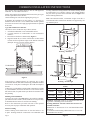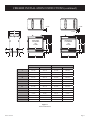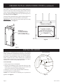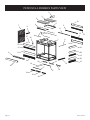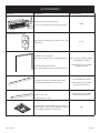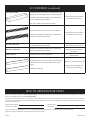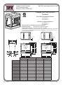
1
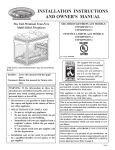
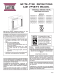
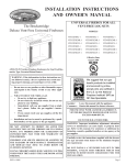
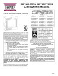
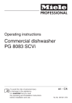
EMPIRE
Comfort Systems
INSTALLATION Instructions
AND Owner's Manual
Premium Vent-Free Universal
Fireboxes
UNIVERSAL FIREBOX FOR ALL
VENT-FREE LOG SETS
SEE-THROUGH FIREBOX MODELS:
VFP36SB2EL-2
VFP36SB2EF-2
PENINSULA FIREBOX MODELS:
VFP36PB2EL-2
VFP36PB2EF-2
GAS-FIRED
ANSI Z21.91 Ventless Fireplace Enclosures for use with any
ANSI Z21.11.2 Gas Fired Decorative Type Unvented Room
Heaters
WARNING: If the information in these instructions are
not followed exactly, a fire or explosion may result causing property damage, personal injury or loss of life.
— Do not store or use gasoline or other flammable vapors
and liquids in the vicinity of this or any other appliance.
—WHAT TO DO IF YOU SMELL GAS
• Do not try to light any appliance.
• Do not touch any electrical switch; do not use any
phone in your building.
• Immediately call your gas supplier from a neighbor’s phone. Follow the gas supplier’s instructions.
• If you cannot reach your gas supplier, call the fire
department.
— Installation and service must be performed by a qualified installer, service agency or the gas supplier.
Do not attempt to modify or alter the
construction of the firebox or its components. Any modification or alteration of
construction may void the warranty of
this firebox.
Children and adults should be alerted to
the hazards of high surface temperature
and should stay away to avoid burns or
clothing ignition.
Young children should be carefully supervised when they are in the same room as
the firebox.
Installer:
Leave this manual with the appliance.
Consumer:Retain this manual for future reference.
For use only with a listed gas-fired unvented decorative room heater not to
exceed 40,000 btu/h.
Do not build a wood fire.
WARNING: Improper installation, adjustment, alteration,
service or maintenance can cause injury or property damage. Refer to this manual. For assistance or additional information, consult a qualified installer, service agency or the
gas supplier.
Carefully review the instructions supplied with the decorative type unvented room heater for the minimum fireplace
size requirement.
DO NOT INSTALL a vent-free log set IN THIS
FIREBOX, UNLESS THIS FIREBOX MEETS THE
MINIMUM DIMENSIONS REQUIRED FOR THE
INSTALLATION.
Page 1
TABLE OF CONTENTS
Section
Page
Important Safety Information . .............................................................................................. 3
Introduction............................................................................................................................ 3
Clearances........................................................................................................................ 4 - 5
Firebox Installation Instructions........................................................................................ 6 - 8
Installing Hood................................................................................................................. 8 - 9
Gas Line Connection.............................................................................................................. 9
Wiring Instructions for Installing a Dual Switch / Receptacle............................................. 10
LK2 Accent Light Accessory............................................................................................... 10
Optional Single Speed Blower Installation Instructions.............................................. 11 - 13
Maintenance......................................................................................................................... 13
Parts List............................................................................................................................... 14
See-Through Firebox Parts View......................................................................................... 15
Peninsula Firebox Parts View............................................................................................... 16
Accessories................................................................................................................... 17 - 18
How To Order Repair Parts.................................................................................................. 18
Quick Reference........................................................................................................... 19 - 22
Service Notes.................................................................................................................. 22-23
Page 2
26557-0-0110
IMPORTANT SAFETY INFORMATION
The installation must conform with local codes or, in
the absence of local codes, with the National Fuel Gas
Code, ANSI Z223.1 (latest edition) and to the National
electrical Code, ANSI/NFPA70 (latest edition).
Any safety screen or guard removed for servicing an
appliance must be replaced prior to operating the appliance. Provide adequate combustion and ventilation
air.
NOTE: Installation and repair should be done by a qualified service person. The appliance should be inspected
before use and at least annually by a qualified service
person. More frequent cleaning may be required due to
excessive lint from carpeting, bedding material, etc. It
is imperative that control compartment, burners and
circulating air passageways of the appliance be kept
clean.
The flow of combustion and ventilation air MUST NOT
be obstructed.
This Empire Comfort Systems Inc. firebox and its
components have been tested and will operate safely when
installed in accordance with this installation manual.
Read all instructions before starting installation, then
follow these instructions carefully during installation
to maximize firebox benefit and safety. Report to your
dealer any parts damaged in shipment.
- Installation other than as instructed by Empire
Comfort Systems Inc.
- Installation and/or use of any component part or
accessory not approved by Empire Comfort Systems
Inc. in combination or assembly with a Empire
Comfort Systems Inc. firebox, not withstanding any
independent testing laboratory or other third party
approval of such component part or accessory.
Any such action may create a possible fire hazard.
Consult your local building codes.
The Empire Comfort Systems Inc. warranty will be
voided by, and Empire Comfort Systems Inc. disclaims
any responsibility for the following actions:
- Installation of any damaged firebox.
- Modification of the firebox or any of the components
parts thereof.
Provide adequate clearance around air openings into
the combustion chamber and adequate accessibility
clearance for servicing and proper operation. NEVER
obstruct the front opening of the appliance.
Firebox Screen.
The firebox screen must be in place when the firebox is
operating.
INTRODUCTION
Instructions to Installer
1.Installer must leave instruction manual with owner after
installation.
2. Installer must have owner fill out and mail warranty card
supplied with firebox.
3.Installer should show owner how to start and operate log set
that is installed into firebox.
Important
All correspondence should refer to complete Model Number,
Serial Number.
Notice: During initial firing of this firebox with a log set installed, its
paint will bake out, and smoke will occur. To prevent triggering of
smoke alarms, ventilate the room in which the unit is installed.
Qualified Installing Agency
Installation and replacement of gas piping, gas utilization
equipment or accessories and repair and servicing of equipment
shall be performed only by a qualified agency. The term "qualified
agency" means any individual, firm, corporation or company
which either in person or through a representative is engaged in
and is responsible for (a) the installation or replacement of gas
26557-0-0110
piping or (b) the connection, installation, repair or servicing of
equipment, who is experienced in such work, familiar with all
precautions required and has complied with all the requirements
of the authority having jurisdiction.
State of Massachusetts: The installation must be made
by a licensed plumber or gas fitter in the Commonwealth
of Massachusetts. The state of Massachusetts requires that
a flexible appliance connector cannot exceed three feet in
length.
Sellers of unvented propane or natural gas-fired supplemental
room heaters shall provide to each purchaser a copy of 527
CMR 30 upon sale of the unit.
In the State of Massachusetts, unvented propane and natural
gas-fired space heaters shall be prohibited in bedrooms and
bathrooms.
The installation must conform with local codes or, in the absence
of local codes, with the National Fuel Gas Code, ANSI Z223.1/
NFPA 54.*
*Available from the American National Standards Institute, Inc., 11 West
42nd St., New York, N.Y. 10036.
Page 3
CLEARANCES
Sidewall Clearances: The clearance from the inside of the firebox to perpendicular combustible side wall should not be less than 1 3/4".
See Figures 1a and 1b.
1 3/4” MIN.
PERPENDICULAR
COMBUSTIBLE
SIDEWALL
42”
MIN.
(CEILING TO
TOP OF HOOD)
1 3/4” MIN.
PERPENDICULAR
COMBUSTIBLE
SIDEWALL
36”
MIN.
42”
MIN.
(CEILING TO
TOP OF HOOD)
36”
MIN.
Figure 1b - Peninsula Firebox Clearances
Figure 1a - See Through Firebox Clearances
Combustible material clearance from front of firebox: 36" minimum
Firebox Side and Back Clearances: The firebox outer casing side(s) require a minimum 1/2" clearance to combustibles.
Top Framing and Finishing: Combustible framing may rest on top of standoffs. Combustible finishing materials may extend to the top
standoff screws on the front edge of the top outer wrap. See Figures 2a and 2b.
COMBUSTIBLE
FINISHED WALL
OR MANTEL
2X4
HEADER
TOP OUTER
WRAP
TOP OUTER
WRAP
STAND OFF
FINISH WITH TRIM KIT
OR NON-COMBUSTIBLE
MATERIAL AS DESIRED.
FIREBOX
Figure 2a - Louvered Models
Page 4
COMBUSTIBLE
FINISHED WALL
OR MANTEL
2X4
HEADER
STAND OFF
FINISH WITH TRIM KIT
OR NON-COMBUSTIBLE
MATERIAL AS DESIRED.
FIREBOX
Figure 2b - Flush Models
26557-0-0110
CLEARANCES
Ceiling Clearances: The ceiling height should not be less than 42" from the top of the hood. See Figures 3a and 3b.
Mantel Clearances: Vent free firebox models must use the hood supplied with the firebox, or one of the optional hood kits available for
each model. If a combustible mantel is installed, it must meet the clearance requirements detailed below.
Grate Clearance: The minimum clearance between the front legs of the grate and the front edges of the firebox is 1 1/2".
CEILING
CEILING
12”
MAX
10”
12”
MAX
10”
MANTEL
24 ½”
MANTEL
42”
MIN.
(CEILING TO
TOP OF HOOD)
COMBUSTIBLES
ALLOWED
8”
42”
MIN.
(CEILING TO
TOP OF HOOD)
22”
20”
18”
3 ½”
13”
13”
5”
17 ½”
5”
15”
6 ½”
84”
MIN.
(CEILING TO FLOOR)
8” COMBUSTIBLES
ALLOWED
6 ½”
11”
3 ½”
16”
84”
MIN.
(CEILING TO FLOOR)
2 ½”
14 ½”
9”
1 ½”
6 ½”
8”
MIN.
4 ½”
MIN.
0”
3/8” COMBUSTIBLE
CLEARANCE REQUIRED
FROM TOP EDGE
STANDARD
OF FIREBOX
HOOD
FIREBOX
FACE
0”
3/8” COMBUSTIBLE
CLEARANCE REQUIRED
FROM TOP EDGE
OF FIREBOX
EXTENDED HOOD
(VB4H SERIES)
(NOT AVAILABLE ON
PENINSULA OPEN END)
FIREBOX
FACE
Figure 3a - Mantel Clearances with Standard Hood
26557-0-0110
Figure 3b - Mantel Clearances with Optional Extended Hood
Page 5
FIREBOX INSTALLATION INSTRUCTIONS
Any vent-free Gas Log Heater must be “For use with approved
ANSI Z21.11.2 unvented room heater.”
Follow and complete the installation instructions of the gas log set
and the requirements of this firebox.
Check all fittings for leaks before lighting the gas log set.
In planning the installation for the firebox, it is necessary to
determine where the unit is to be installed and whether optional
accessories are desired. Gas supply piping should also be planned
at this time.
covering and firebox facing material. The firebox framing should
be constructed of 2 x 4 lumber or heavier. The framing headers
may rest on the top of the firebox standoffs. Refer to Figure 5 for
firebox framing dimensions.
Note: On Peninsula models, a maximum weight of 250 lbs. is
recommended when construction materials are supported by the
top standoff spacers.
A gas shut off must be in this line.
The firebox can be mounted on any of these surfaces:
1. A flat hard combustible or non-combustible surface.
2.A raised platform of combustible or non-combustible
material.
3. Recessed into the floor as illustrated by Figure 4.
4. Supported under all (4) corners of the firebox so that contact
is made on all four perimeter edges on the bottom of the unit
(Example: Four (4) concrete masonry blocks).
A
C
B
Framing - Peninsula
FLUSH FACE
LOUVERED
A
COMBUSTIBLE MATERIALS ALLOWED
C
Figure 4
If the firebox is installed directly on carpeting, tile or other
combustible material other than wood flooring, it should be installed
on a metal or wood panel extending the full width and depth of
the unit.
At this point, you should have decided what components to include
in your installation, and where the firebox is to be located. If this
has not been done, stop and consult your dealer for assistance with
this planning.
Planning Your Installation
Accessory kits such as the FBB5 Blower kit, Trim kits, Mantles,
plus other Decorative Frame, Hood, and Door accessory kits may
be installed after the firebox is secured to the framing.
Refer to the instructions provided with each of the optional
accessory kits for proper installation and operation.
Firebox Framing
Firebox framing can be built before or after the firebox is set
in place. Framing should be constructed to accommodate wall
Page 6
B
Framing - See-Through
Premium Vent-Free Firebox Framing Dimensions (in
inches)
"A"
"B"
"C"*
Model
Framing
Framing
Framing
Height
Width
Depth
VFP36SB
41 1/2"
40"
23"*
VFP36PB
41 1/2"
39"**
23"*
Attention: Add height of base to "A" Dimension when elevating firebox if installing on an elevated base.
Framing dimension A incudes a three inch clearance for
standoffs on firebox.
*Dimension "C" assumes use of 1/2" wall board flush to both
front faces.
** Peninsula model framing width assumes use of 1/2" wall
board flush to the end face.
Figure 5
26557-0-0110
FIREBOX INSTALLATION INSTRUCTIONS (continued)
2 9/16”
2 9/16”
G
C
2 9/16”
SEE THRU
LOUVERED
OR
FLUSH
DMNA
PENINSULA
LOUVERED
OR
FLUSH
H
F
K
J
J
I
L
I
E
B
E
B
A
H
F
K
L
DMNA
LOUVERED PANELS
VFP36SB
VFP36PB
38 1/8"
38 1/8"
FLUSH PANELS
VFP36SB
VFP36PB
38 1/8"
38 1/8"
B
C
D
E
F
G
39"
24"
25 1/2"
36"
34 1/4"
29 1/8"
39"
24"
25 1/2"
36"
35 1/4"
29 1/8"
39"
24"
25 1/2"
36"
34 1/4"
29 1/8"
39"
24"
25 1/2"
36"
35 1/4"
29 1/8"
H
I
J
K
L
M
N
41 1/8"
1 1/4"
6 1/8"
8 1/2"
6"
27 5/8"
36 7/8"
41 1/8"
1 1/4"
6 1/8"
8 1/2"
6"
27 5/8"
36 7/8"
41 1/8"
1 1/4"
6 1/8"
8 1/2"
6"
27 5/8"
36 7/8"
41 1/8"
1 1/4"
6 1/8"
8 1/2"
6"
27 5/8"
36 7/8"
Figure 6
Firebox Dimensions
26557-0-0110
Page 7
FIREBOX INSTALLATION INSTRUCTIONS (continued)
Locating Firebox
Place firebox in framed opening. Attach the framing brackets to
the firebox and secure firebox to framing. Different hole locations
can be used for finishing materials with thicknesses of 3/8", 1/2"
and 3/4". Secure the brackets with screws provided using two (2)
per framing bracket. See Figure 7.
Framing brackets should fit directly against framing material. Use
at least one (1) nail or screw per bracket to secure in place.
IMPORTANT! Check squareness of the firebox prior to securing
to framed opening. See Figure 8.
FIREBOX OPENING
CHECK TO SEE
THAT BOX IS SQUARE
PRIOR TO ATTACHING TO
FRAMING
ATTACH (4)
FRAMING BRACKETS
TO SIDE(S) OF FIREBOX
PRIOR TO INSTALLING
UNIT TO FRAMED OPENING
Figure 8
Figure 7
INSTALLING HOOD
Louvered Models
Black hoods are furnished with each firebox (or the optional
hood(s)) and MUST be installed before the firebox is used. Failure
to do so may create a possible fire hazard. For shipping purposes, the hoods are located behind the upper louver(s), or inside the
firebox on flush face units. If brass, stainless steel, or hammered
pewter hoods are desired, they can be purchased as an option.
Attachment is the same as the standard black hood.
INNER FIREBOX TOP
Louvered Models
1. Remove upper louver, or flush panel.
2. Place the top hood flange on top of the inner firebox top, then
install three screws through the firebox top from below and
screw into the pilot holes in the hood flange (B).
3.Install one (1) screw at each end of the hood as shown (C).
4. Re-install louver(s) or flush panel(s).
Caution: All hoods must be installed prior to operation of
appliance. See Figure 9.
Page 8
B
C
Figure 9
26557-0-0110
INSTALLING HOOD (continued)
Extended Hoods
If your non-combustible facing material is over 1" in thickness and will be used to finish this firebox, extended hoods are available that
will extend out 2" farther into the room. Extended hoods are not available for the peninsula open ends. Contact your local dealer for
details.
Extended Hoods
VB4H36BL
Standard Black (1 each)
VB4H36BR
Polished Brass (1 each)
VB4H36SS
Stainless Steel (1 each)
VB4H36HP
Hammered Pewter (1 each)
Finishing
All joints (top, bottom and sides), where the wall or decorative facing material meets the firebox surround should be sealed with a noncombustible material.
Hearth extensions are required for these fireboxes.
Flush panels, louvers, and decorative louver panels are interchangeable, and may be mixed and matched as desired (i.e. Flush panel on
bottom with louvered panel at top, or vice versa).
GAS LINE CONNECTION
The firebox is designed to accept a gas line for an approved ventfree gas logset. Have the line installed by a qualified service person
in accordance with all building codes. Consult local building codes
to properly size the gas supply line leading to the connection of the
logset burner. The state of Massachusetts requires that a flexible
appliance connector cannot exceed three feet in length.
Gas access holes are provided through the side panel(s) of
the firebox. See Figure 10. Carefully remove the indented
knockout in the ceramic brick panel using a drill or utility knife.
See Figure 11.
Check gas type. Use only the gas type indicated on the gas log
set rating plate. If the gas listed on the plate is not your type of
gas supply, DO NOT INSTALL. Contact your dealer for proper
model.
GAS LINE
ACCESS
HOLES
Always use an external regulator for all LP fireboxes to reduce the
supply tank pressure to a maximum of 14" w.c. This is in addition
to the regulator fitted to the log set.
WA R NING : CONNECTION D I R ECT LY TO AN
UNREGULATED L.P. TANK CAN CAUSE EXPLOSION.
Figure 10
Install only a ANSI Z21.11.2 vent-free log set into this firebox.
Figure 11
26557-0-0110
Page 9
WIRING INSTRUCTIONS FOR INSTALLING A DUAL SWITCH / RECEPTACLE
In order to install both the optional Blower and Accent Light accessories, it will be necessary to install the junction box so that
the Duplex Receptacle wiring is split. This will allow each side of
the receptacle to operate independently off separate wall switches.
See diagram below.
Note: To operate the FBB5 Blower accessory with a variable
speed control, the SCV1 Variable Speed Control Kit should be installed to control the power to one side of the duplex receptacle.
#1
ACCENT LIGHT
WALL SWITCH
#2
BLOWER
WALL
SWITCH
BLACK
TO 120V
CIRCUIT
BREAKER
REMOVE TAB ON HOT SIDE
OF DUPLEX RECEPTACLE
TO SPLIT LUGS
RED
PLUG
FOR
CONTROLS
BLACK
WHITE
PLUG
FOR
BLOWER
WHITE
GROUND
DOUBLE SWITCH BOX
(INSTALLER PROVIDED)
3-WIRE, GROUNDED
CONDUCTOR
(BY OTHERS)
FIREPLACE
CONTROL
COMPARTMENT
DUAL SWITCH ELECTRICAL WIRING TO FIREPLACE RECEPTACLE
1.To wire Junction Box Receptacle, remove the tab on the side
of the receptacle (hot side) to split receptacle. This will be
required to separate blower and Accent Light circuits.
2. Power for switched and live sides of Duplex Receptacle must
come from the same power source. (One circuit breaker on
main panel must switch all power off.)
3. From the wall box to the fireplace a 3-wire conductor with
ground is recommended, however (2) two-wire conductors
with grounds may be used in place of a 3-wire conductor with
a ground if the black wires from the Accent Light and blower
accessories are identified.
4.Two wall switches may be used to activate the two receptacle
plugs independently.
Note: Wiring to the Junction Box should be run through the 7/8"
diameter access hole located on one of the sides of the fireplace
outer wall. A Romex type connector is provided and should be
used to protect and restrain the wiring where it passes through
the fireplace outer wall. The Junction Box should be positioned in
the lower compartment of the fireplace/firebox so that it does not
interfere with moving parts of the blower assembly. The Junction
Box incorporates magnets on the bottom side to retain and reduce
the chance of movement or vibration during blower operation.
Note: If only the blower option is to be installed, wiring may be
performed as described and illustrated in the following Blower
Installation section.
LK2 ACCENT LIGHT ACCESSORY
An Accent Light Kit model LK2 is available for installation in
the top of the firebox. Providing the junction box has been prewired with separate circuits as described in the "Wiring for a dual
switch/receptacle" section, the Accent Light kit may be installed
at any time on louvered models, or on flush panel models prior to
the upper panels being covered with finishing materials.
Page 10
Follow the instructions provided with the LK2 Accent Light kit
for proper installation in the fireplace/firebox.
26557-0-0110
OPTIONAL SINGLE SPEED BLOWER INSTALLATION INSTRUCTIONS
Attention:Install blower assembly before connecting gas inlet
supply line.
Wiring
The appliance, when installed, must be electrically grounded in
accordance with local codes or, in the absence of local codes,
with the National Electrical Code, ANSI/NFPA 70, if an external electrical source is utilized. This appliance is equipped with
a three-prong [grounding] plug for your protection against
shock hazard and should be plugged directly into a properly
grounded three-prong receptacle. Do not cut or remove the
grounding prong from this plug. For an ungrounded receptacle,
an adapter, which has two prongs and a wire for grounding, can
be purchased, plugged into the ungrounded receptacle and its wire
connected to the receptacle mounting screw. With this wire completing the ground, the appliance cord plug can be plugged into
the adapter and be electrically grounded.
Caution: Label all wires prior to disconnection when servicing controls. Wiring errors can cause improper and dangerous
operation. Verify proper operation after servicing.
A factory included junction box is located on the lower right
side of the firebox. Wiring must be fed through the 7/8" diameter hole provided on the lower side of the firebox, and
secured to the outer wrap with the clamp provided. Leave
approximately 6” of wire in the junction box for connection.
Attach black wire to one side of the receptacle and white wire
to opposite side of receptacle. The ground wire should be attached to the green (ground) screw. See Figure 12.
Install the receptacle into the junction box as illustrated.
Attach cover plate. Place Junction Box so that it is approximately 8 to 12" away from the outer wrap wall. Secure wiring
at outer wrap of fireplace with wire clamp provided.
Attention: If installed, do not damage gas inlet supply line
when blower assembly is inserted into firebox. In some cases,
removal of the gas inlet supply line may be necessary.
3. Determine which type of firebox you have prior to installation. See Figures 13 and 14.
Note: Junction box is to be located in the lower compartment of
the firebox and must be pre-wired at time of firebox installation for use with blower assembly. A standard ON/OFF
wall switch or optional SCV1 Variable Speed Control Kit
should be installed to activate power to the Junction Box
and provide power for the operation of the FBB5 Blower
assembly. It is recommended that installation of the wiring be performed by a qualified electrician. See Figures 12
and 13.
1. If installed, turn OFF gas supply to firebox/gas log.
2. If applicable, turn OFF electric supply to firebox.
CAUTION: ALL WIRING SHOULD BE DONE BY
A QUALIFIED ELECTRICIAN AND SHALL BE IN
COMPLIANCE WITH ALL LOCAL, CITY AND STATE
BUILDING CODES. BEFORE MAKING THE ELECTRICAL CONNECTION, MAKE SURE THAT MAIN POWER
SUPPLY IS DISCONNECTED. THE APPLIANCE, WHEN
INSTALLED, MUST BE ELECTRICALLY GROUNDED
IN ACCORDANCE WITH LOCAL CODES, WITH THE
NATIONAL ELECTRICAL CODE ANSI/NFPA 70 (LATEST EDITION).
To install the blower kit, access the junction box, or install a light
kit, remove the access cover plate and/or lower louvers or flush
panels as illustrated by figures 13 and 14.
Flush Or Louvered
Models
Figure 13
BLOWER AND JUNCTION
BOX ACCESS COVER
PLATE
Flush Face Models With
Raised Hearth Extensions
Figure 12
26557-0-0110
Figure 14
Page 11
4. Insert blower assembly into interior, bottom of firebox. Position blower assembly so that you align the notch on back
of blower assembly with the center screw on side/end panel,
then push the blower assembly against firebox outer panel.
The blower wheel must be centered with the side/end wall of
the firebox. The magnets on the back and bottom of blower
assembly will sufficiently hold blower assembly in place. See
Figure 16.
5.Once the blower assembly is in position, locate the plug button in the top corner of the firebox. Remove the plug with a
standard screwdriver and discard plug.
6. Next, find the fan control switch and wire assembly. Feed
the wires through the hole at the top of the firebox. Feed the
wires over the firebox top and down between the firebox side
and outer wrap then, secure the fan control switch with (2) #6
screws provided. See Figure 15.
Note: This blower is equipped with a heat activated fan control
switch. Blower will operate when the firebox warms up,
and will turn off automatically when the firebox cools
down. The time will vary for the activation of the fan control switch depending on several factors including firebox/
log set sizing, BTU input variables, and log set positioning. Generally, it may take from 5 to 20 minutes to activate
blower/fan control from a cold start.
WIRES
FROM FAN
CONTROL
SWITCH
HEARTH
OUTER
WRAP
JUNCTION
BOX
FAN CONTROL
SWITCH LOCATION
POWER CORD
Figure 15
7. The fan control wires will slide down between the firebox
and outer wrap near the blower assembly. See Figure 16.
8.One fan control wire will have a 1/4” female terminal that
must be attached to the open terminal on the blower motor.
See Figure 19, Connection A.
9.The other fan control wire has a 1/4” male terminal. Attach
this terminal to the open terminal on the blower power cord.
See Figure 19, Connection B
10. Route the wires away from moving parts of the blower assembly and retain wires together near the blower motor using
the plastic purse clip provided.
11.To complete the installation, plug the power cord into the
junction box receptacle previously installed in the bottom of
the firebox. See Figures 16 and 18.
12.Once all connections are made electrically, it is recommended that you test the blower fan control operation by turning
on power to the blower (Caution: 110 Volt). Then apply heat
to the fan control switch inside the firebox with a lighter or
match until blower is activated. Once blower is activated,
check for proper operation. Do not place hands near blower
assembly or other wiring while power is on.
13. Replace blower access plate and louvers or flush panels. See
Figures 13 and 14.
14.This completes the installation of the optional FBB5 Blower
kit accessory.
Page 12
BLOWER ASSEMBLY
(CENTER AND INSTALL
AGAINST OUTER WRAP
AS SHOWN)
Figure 16
USE SCVI VARIABLE SPEED
CONTROL OPTION, OR STANDARD
ON/OFF WALL SWITCH TO
OPERATE OPTIONAL BLOWER
Figure 17
26557-0-0110
Blower Motor
The blower motor does not have oiling holes. Do not attempt to
oil the blower motor.
JUNCTION BOX
110 VOLT AC
FAN/MOTOR
ASSEMBLY
Blower Wheels
The blower wheels will collect lint and could require periodic
cleaning. If the air output decreases or the noise level increases,
it indicates a dirty blower wheel. Remove fan and clean blower
wheels.
BLACK
FAN
SWITCH
WHITE
Figure 18
2
1
A
B
1
2
FBB5
R8199
BLOWER ASSEMBLY COMPLETE
FAN CONTROL SWITCH
Figure 19
MAINTENANCE
Keep the control compartment, logs and burner area surrounding the
logs clean by vacuuming or brushing area at least twice a year.
Never obstruct the flow of the combustion and ventilation air. Keep
the front of the firebox clear of all obstacles and materials.
THE LOGS CAN GET VERY HOT – HANDLE ONLY WHEN
COOL.
Screens must be closed during operation.
Always turn off gas to the pilot before cleaning. For relighting,
refer to lighting instructions located on the log set.
26557-0-0110
Page 13
PARTS LIST
Index
Number
1
2
3
4
5
6
7
8
9
10
11
12
13
14
15
16
17
18
19
20
21
22
23
24
25
26
27
VFP36SB2EL
17149
R9655
24067
R7052
R9631
19945
20145
20073
18807
18808
19990
23004
R9293
R9295
R9292
10554
19401
Part Number
VFP36SB2EF
VFP36PB2EL
17149
17149
R9655
R9655
24067
24067
R7052
R7052
R9633
R9631
R9631
19945
19945
20145
20145
24056
20073
20073
18807
18807
18808
18808
24059
24058
19990
19990
23004
23004
R9293
R9293
R9295
R9295
R9292
R9292
R9634
10554
10554
24051
24052
19401
19401
VFP36PB2EF
17149
R9655
24067
R7052
R9633
R9631
19945
20145
24056
20073
18807
18808
24059
24058
19990
23004
R9293
R9295
R9292
R9634
10554
24051
24052
24054
24053
19401
Description
FIREBOX ASSEMBLY
TOP STANDOFF
INSULATION - TOP
INSULATION SUPPORT
SCREEN ROD
SCREEN ROD
BRICK PANEL - SIDE BULK
BRICK LINER BRACKET
HOOD
PENINSULA HOOD
INNER AIR BAFFLE
LOUVER ASSEMBLY - UPPER
LOUVER ASSEMBLY - LOWER
UPPER LOUVER ASSEMBLY
LOWER LOUVER ASSEMBLY
BLOWER COVER PLATE
HEARTH RETAINER
HEARTH LEDGE - LEFT
HEARTH LEDGE - CENTER
HEARTH LEDGE - RIGHT
HEARTH LEDGE
NAILING FLANGE
FLUSH PANEL - UPPER - LONG
FLUSH PANEL - LOWER - LONG
FLUSH PANEL - UPPER - SHORT
FLUSH PANEL - LOWER - SHORT
BRICK LINER BRACKET - LOWER
See Page 15 for See-Through Models VFP36SB2E(L,F) Parts View for ordering parts.
See Page 16 for Peninsula Models VFP36PB2E(L,F) Parts View for ordering parts.
Use Only Manufacturer’s Replacement Parts. Use of Any Other Parts Could Cause Injury Or Death.
Page 14
26557-0-0110
SEE-THROUGH FIREBOX PARTS VIEW
2
3
3
23
4
4
7
11
8
12
9
5
13
27
22
1
8
23
7
12
24
24
11
16
9
20
27
17
18
26557-0-0110
13
19
17
19
18
20
Page 15
PENINSULA FIREBOX PARTS VIEW
2
3
3
7
23
4
4
9
8
11
5
27
13
22
1
6
24
23
11
12
12
10
24
25
14
13
9
19
20
17
18
Page 16
16
17
19
26
21
15
18
20
26557-0-0110
ACCESSORIES
Accessory
Fan Kit
Description
Designed to provide forced air flow.
Note: For use with louvered or flush panel models.
Model Numbers
FBB5
Variable Speed Control Kit
Wall mounted variable speed control for use with
FBB5 blower
SCV-1
Frame Kits
Standard 3-Piece Frame Kits
Black, Brass, Stainless Steel, or Hammered Pewter
Extruded Aluminum Frame Kits
Black, Brass, Stainless Steel, or Hammered Pewter
For use with See-Through models:
VFP36SB2E(L,F) ONLY
Contact dealer for all available
optional frame kits
Bottom Trim Strip
Available as optional kits in Black, Brass, Hammered Pewter, and Stainless Steel finishes.
Standard Hood
For VFP36SB2E(F,L) ONLY
Contact dealer for all available
optional trim accessories
Brass hood = BR
Stainless Steel = SS
Contact dealer for all available
optional hood accessories
Hammered Pewter = HP
Accent Light Kit
Optional light kit that installs in top of firebox to
enhance logset. Operates with a Rheostat control to
vary brightness of light for desired effect.
26557-0-0110
LK2
Page 17
ACCESSORIES (continued)
Extended 4" Hoods
Extended hoods that extend out 2" farther than the standard hoods, to accommodate thicker surround materials.
Available as optional kits in Black, Brass, Hammered
Pewter, and Stainless Steel finishes.
Contact dealer for all available
optional hood accessories
Note: Not available for Peninsula open ends.
Louvers
Styles include Slat, Mission, Arch, and Leaf Patterns.
Available as optional kits in Black, Brass, Hammered
Pewter, and Stainless Steel finishes.
Decorative Door Kits
Available as optional kits in Black, Brass, Hammered
Pewter, and Stainless Steel finishes.
Decorative Frame Kits
Available as optional kits in Black, Brass, Hammered
Pewter, and Stainless Steel finishes.
Mantel Systems
Available in various styles and finishes.
Contact dealer for all available
optional louver accessories
Contact dealer for all available
optional frame kit accessories
Contact dealer for all available
optional decorative door kit
accessories
Contact dealer for all available
mantel options.
Flush Panel Kits
Flush panel kits may be used to replace louvered panels
as desired for the See-Through and Peninsula firebox
models.
Available in black only.
FPK22 (For Peninsula open end)
FPK36 (For See-Through and
Peninsula front openings)
HOW TO ORDER REPAIR PARTS
Parts can be ordered through your service person or dealer. For best results, the service person or dealer should order parts through the distributor.
Parts can be shipped directly to the service person/dealer.
All parts listed in the Parts List have a Part Number. When ordering parts, first obtain the Model Number from the name plate on your equipment. Then determine the Part Number (not the Index Number) and the Description of each part from the following appropriate illustration and list. Be sure
to give all this information.
Firebox Model Number
Firebox Serial Number
Part Description
Part Number
Do not order bolts, screws, washers or nuts. They are standard hardware items and can be purchased at any local hardware store.
Shipments contingent upon strikes, fires and all causes beyond our control.
Page 18
26557-0-0110
Web Site: www.empirecomfort.com
Empire Comfort Systems
918 Freeburg Avenue
Belleville, Illinois 62220-2623
EMPIRE
Comfort Systems
Premium Vent-Free Universal
Fireboxes
GAS-FIRED
SEE-THROUGH FIREBOX MODELS:
VFP36SB2EL-2
VFP36SB2EF-2
PENINSULA FIREBOX MODELS:
VFP36PB2EL-2
VFP36PB2EF-2
36-inch Firebox accomodates the following Log Sets:
Refractory Log Set:
LSU-18RR, LSU-24RR, LSU-30RR
Ceramic Fiber Log Set: LSU-18SF, LSU-24SF, LSU-30SF
Banded Brick Liners are made from Ceramic Fiber for rich detail and lasting beauty. Banded Brick
Liners have dark "creamed-coffee" bricks with charcoal mortar in running bond courses, plus an
accent band of diagonal bricks.
2 9/16”
2 9/16”
G
C
2 9/16”
SEE THRU
LOUVERED
OR
FLUSH
DMNA
PENINSULA
LOUVERED
OR
FLUSH
H
F
K
J
J
I
L
I
E
B
E
B
LOUVERED PANELS
26557-0-0110
H
F
K
L
DMNA
FLUSH PANELS
VFP36SB
VFP36PB
VFP36SB
VFP36PB
A
38 1/8"
38 1/8"
38 1/8"
38 1/8"
B
39"
39"
39"
39"
C
24"
24"
24"
24"
D
25 1/2"
25 1/2"
25 1/2"
25 1/2"
E
36"
36"
36"
36"
F
34 1/4"
35 1/4"
34 1/4"
35 1/4"
G
29 1/8"
29 1/8"
29 1/8"
29 1/8"
H
41 1/8"
41 1/8"
41 1/8"
41 1/8"
I
1 1/4"
1 1/4"
1 1/4"
1 1/4"
J
6 1/8"
6 1/8"
6 1/8"
6 1/8"
K
8 1/2"
8 1/2"
8 1/2"
8 1/2"
L
6"
6"
6"
6"
M
27 5/8"
27 5/8"
27 5/8"
27 5/8"
N
36 7/8"
36 7/8"
36 7/8"
36 7/8"
Page 19
Web Site: www.empirecomfort.com
Empire Comfort Systems
918 Freeburg Avenue
Belleville, Illinois 62220-2623
EMPIRE
Comfort Systems
Premium Vent-Free Universal Fireboxes
SEE-THROUGH FIREBOX MODELS:
PENINSULA FIREBOX MODELS:
VFP36SB2EL-2
VFP36PB2EL-2
VFP36SB2EF-2
VFP36PB2EF-2
Clearances
Combustible material clearance from front of firebox: 36" minimum
Sidewall Clearances: The clearance from the inside of the firebox to perpendicular combustible side wall should not be less than 1 3/4".
Firebox Side and Back Clearances: The firebox outer casing side(s) require a minimum 1/2" clearance to combustibles.
Top Framing and Finishing: Combustible framing may rest on top of standoffs. Combustible finishing materials may extend to the top standoff screws on the
front edge of the top outer wrap.
Ceiling Clearances: The ceiling height should not be less than 42" from the top of the hood.
Mantel Clearances: Vent free firebox models must use the hood supplied with the firebox, or one of the optional hood kits available for each model. If a combustible mantel is installed, it must meet the clearance requirements detailed below.
Grate Clearance: The minimum clearance between the front legs of the grate and the front edges of the firebox is 1 1/2".
CEILING
CEILING
12”
MAX
10”
12”
MAX
10”
MANTEL
MANTEL
42”
MIN.
(CEILING TO
TOP OF HOOD)
COMBUSTIBLES
ALLOWED
8”
15”
24 ½”
42”
MIN.
(CEILING TO
TOP OF HOOD)
6 ½”
8” COMBUSTIBLES
ALLOWED
22”
6 ½”
20”
13”
5”
84”
MIN.
(CEILING TO FLOOR)
17 ½”
5”
18”
3 ½”
13”
11”
3 ½”
9”
16”
84”
MIN.
(CEILING TO FLOOR)
2 ½”
14 ½”
1 ½”
6 ½”
8”
MIN.
4 ½”
MIN.
0”
3/8” COMBUSTIBLE
CLEARANCE REQUIRED
FROM TOP EDGE
STANDARD
OF FIREBOX
HOOD
FIREBOX
FACE
0”
3/8” COMBUSTIBLE
CLEARANCE REQUIRED
FROM TOP EDGE
OF FIREBOX
EXTENDED HOOD
(VB4H SERIES)
(NOT AVAILABLE ON
PENINSULA OPEN END)
FIREBOX
FACE
Mantel Clearances with Standard Hood
Page 20
Mantel Clearances with Optional Extended Hood
26557-0-0110
EMPIRE
Comfort Systems
Web Site: www.empirecomfort.com
Empire Comfort Systems
918 Freeburg Avenue
Belleville, Illinois 62220-2623
Premium Vent-Free Universal Fireboxes
SEE-THROUGH FIREBOX MODELS:
PENINSULA FIREBOX MODELS:
VFP36SB2EL-2
VFP36PB2EL-2
VFP36SB2EF-2
VFP36PB2EF-2
Clearances (continued)
1 3/4” MIN.
PERPENDICULAR
COMBUSTIBLE
SIDEWALL
Framing
42”
MIN.
(CEILING TO
TOP OF HOOD)
A
C
B
Framing - Peninsula
36”
MIN.
See Through Firebox Clearances
1 3/4” MIN.
PERPENDICULAR
COMBUSTIBLE
SIDEWALL
42”
MIN.
(CEILING TO
TOP OF HOOD)
A
C
B
Framing - See-Through
Premium Vent-Free Firebox Framing Dimensions (inches)
36”
MIN.
Peninsula Firebox Clearances
26557-0-0110
"A"
"B"
"C"*
Model
Framing Height
Framing Width
Framing Depth
VFP36SB
41 1/2"
40"
23"*
VFP36PB
41 1/2"
39"**
23"*
Attention: Add height of base to "A" Dimension when elevating firebox if
installing on an elevated base.
Framing dimension A incudes a three inch clearance for standoffs on
firebox.
*
Dimension "C" assumes use of 1/2" wall board flush to both front faces.
** Peninsula model framing width assumes use of 1/2" wall board flush to
the end face.
Page 21
SERVICE NOTES
Page 22
26557-0-0110
SERVICE NOTES
26557-0-0110
Page 23
EMPIRE
Comfort Systems
Empire Comfort Systems Inc.
918 Freeburg Ave. Belleville, IL 62220
PH: 618-233-7420 or 800-851-3153
FAX: 618-233-7097 or 800-443-8648
[email protected]
www.empirecomfort.com
Page 24
26557-0-0110