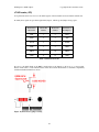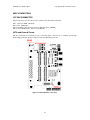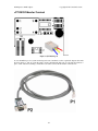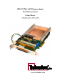
1
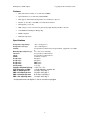
PMC/CCPMC to PCI Express adapter
For Delivery Systems
Product Manual
P/N 6768, 6773, 6777 & 6778
www.technobox.com
Table of Contents
INTRODUCTION .................................................................................................................................................... 1
FEATURES ............................................................................................................................................................ 2
SPECIFICATIONS .................................................................................................................................................. 2
REFERENCES ........................................................................................................................................................ 3
MONITOR SUBSYSTEM ......................................................................................................................................... 3
LIGHT EMITTING DIODES (LEDS) ...................................................................................................................... 4
SOFTWARE REQUIREMENTS ................................................................................................................................ 6
CONFIGURATION.................................................................................................................................................. 6
DIP SWITCHES ..................................................................................................................................................... 7
PCI EXPRESS 4X EDGE CONNECTOR. ................................................................................................................. 9
PMC CONNECTORS JN1, JN2 JN3 AND JN4. ................................................................................................... 13
PMC JN4/J1 CONNECTOR(REAR I/O) .............................................................................................................. 18
SCSI STYLE CONNECTOR MOUNTING BRACKET VIEW. ................................................................................ 21
JTAG HEADER (JP3) ......................................................................................................................................... 22
MISC CONNECTORS..................................................................................................................................... 23
JP5 FAN CONNECTOR.................................................................................................................................. 23
INTA AND GROUND TURRETS .......................................................................................................................... 23
JP6, JP8, JP9 FACTORY USE ONLY ................................................................................................................... 26
POWER OVERVIEW ............................................................................................................................................ 27
APPENDIX A – CCPMC MOUNTING AND CARRIER INSTALLATION ................................................................. 28
CARRIER AND PMC INSTALLATION ................................................................................................................. 28
CONDUCTION COOLED PMC INSTALLATION ON CARRIER .............................................................................. 28
CARRIER INSTALLATION INTO PCI SLOT. ........................................................................................................ 29
CAUTIONS .......................................................................................................................................................... 29
THERMAL FRAME. ............................................................................................................................................. 29
APPENDIX B RS-232 SERIAL MONITOR............................................................................................................ 30
APPENDIX C – PRINTED CIRCUIT DESIGN ........................................................................................................ 36
APPENDIX D – TYPICAL APPLICATIONS. ........................................................................................................... 37
TECHNOBOX 6768 WITH A 5100 BREAK OUT PANEL. ........................................................................................ 37
TECHNOBOX CCPMC CARRIER WITH FAN AND HEAT SINK. ........................................................................... 37
TECHNOBOX CCPMC CARRIER WITHOUT A FAN. ........................................................................................... 38
TECHNOBOX CCPMC CARRIER FAN REMOVAL............................................................................................... 39
APPENDIX E FRONT PANEL WIRING AIDS .......................................................................................................... 40
APPENDIX F MECH. DIMENSIONS ..................................................................................................................... 41
FIGURES
Figure 1 PMC-X to PCI Express adapter block diagram................................................................................ 1
Figure 2 LED locations ................................................................................................................................. 4
Figure 3 Data path from PCI Express to PMC ............................................................................................... 6
Figure 4 PCI Express side A......................................................................................................................... 11
Figure 5 PCI Express side B......................................................................................................................... 12
Figure 6 JN1, JN2, JN3 and JN4 .................................................................................................................. 13
Figure 9 Standard differential pairing........................................................................................................... 19
Figure 10 VITA 46 differential pairing ....................................................................................................... 20
Figure 7 68-pin connector numbering .......................................................................................................... 21
Figure 8 68-pin SCSI style with major dimensions ...................................................................................... 21
Figure 11 JTAG Factory jumper setting....................................................................................................... 22
Figure 12 GND and INTA connections........................................................................................................ 23
Figure 13 JP7 RS232 port............................................................................................................................. 24
Figure 14 RS232 cable diagrams.................................................................................................................. 25
Figure 15 Factory use only ........................................................................................................................... 26
Figure 16 Power supply architecture ........................................................................................................... 27
Figure 17 Thermal Frame and anti-fret parts................................................................................................ 29
Figure 18 Example of monitor setup ............................................................................................................ 30
Figure 19 Port settings for the PC ................................................................................................................ 30
Figure 20 Main screen-shot. ......................................................................................................................... 31
Figure 21 Voltages/Currents Monitored, temp. sensor locations. ................................................................ 32
Figure 22 Printed Circuit Placement Side B................................................................................................. 36
Figure 23 Printed Circuit Placement Side A................................................................................................. 36
Figure 24 Adjacent slot interference, dimensions in inches ......................................................................... 41
Tables
Table 1 - DIP switch S1 settings ................................................................................................................... 7
Table 2 PCI Express signals ......................................................................................................................... 10
Table 3 JN1 pinout ....................................................................................................................................... 14
Table 4 JN2 pinout ....................................................................................................................................... 15
Table 5 JN3 pinout ....................................................................................................................................... 16
Table 6 JN4 pinout ...................................................................................................................................... 17
Table 7 JTAG functions JP3......................................................................................................................... 22
ii
Purpose/Scope
This hardware manual aids in installation, configuration and use of Technobox Products.
Life support statement
This Technobox product is not designed, intended, specified or tested for life support use, any life support
usage of this product is the responsibility of the purchaser of this product.
Static and handling precautions
Static precautions are mandatory in handling this equipment. Use a conductive wrist strap and handle the
board in a static-free environment. Avoid touching components or connectors on the PMC, it is best to hold
the PMC by the edges.
Warranty
Warranty information is found on the Technobox website www.technobox.com For product warranty or
repairs please call or email Technobox for an RMA number
Technical Support.
Please refer to the distribution CD received with the board for sample software and drivers or call
Technobox for support with drivers and operating systems.
(609)-267-8988 ext 2
[email protected]
www.technobox.com/support.htm
Part Numbers
P/N 6768 PMC to PCI Express adapter – 4 lane, CCPMC, Standard PN4 differential I/O (ROHS)
P/N 6773 PMC to PCI Express adapter – 4 lane, CCPMC, VITA46, PN4 differential I/O (ROHS)
P/N 6777 PMC to PCI Express adapter – 4 lane, PMC, Standard PN4 I/O differential (ROHS)
P/N 6778 PMC to PCI Express adapter – 4 lane, PMC, VITA46, PN4 I/O differential (ROHS)
P/N 6351 Adapter cable required for accessing the monitor function.
Liability Limitation.
IN NO EVENT SHALL TECHNOBOX, INC. BE LIABLE FOR SPECIAL, INCIDENTAL, OR CONSEQUENTIAL
DAMAGES, INCLUDING BUT NOT LIMITED TO LOSS OF PROFIT OR OPPORTUNITY. FOR ANY
PRODUCT NOT MANUFACTURED BY TECHNOBOX, INC., THE CUSTOMER'S SOLE AND EXCLUSIVE
REMEDY IS STATED IN THE MANUFACTURER'S OR PUBLISHER'S END USER WARRANTY
ACCOMPANYING THE PRODUCT. IN NO EVENT SHALL TECHNOBOX, INC.'S LIABILITY EXCEED THE
REPAIR, REPLACEMENT OR COST OF THE SPECIFIC PRODUCT PURCHASED FROM TECHNOBOX, INC.
SOME STATES MAY NOT RECOGNIZE A DISCLAIMER OR LIMITATION OF WARRANTIES AND/OR
LIMITATION OF LIABILITY SO THE ABOVE DISCLAIMERS MAY NOT APPLY. CUSTOMER MAY ALSO
HAVE DIFFERENT AND/OR ADDITIONAL RIGHTS AND REMEDIES THAT VARY FROM STATE TO
STATE.
Manual Revision
Rev 0 – 09/01/2011 – Initial release
iii
PCI Express to PMC adapter
Copyright © 2011, Technobox, Inc
Figure 1 PMC-X to PCI Express adapter block diagram
Introduction
The Technobox PMC/CCPMC to PCI Express family of carrier cards host a Conduction Cooled PMC “
CCPMC” in a PCI Express edge card slot. Standard IEEE1386 PMCs are hosted in a similar, but smaller,
mechanical configuration without the heatsink.
The PMC is reverse mounted providing PN4 rear IO at the PCI mounting bracket via a 68 pin SCSI style
connector J1. The differential pairing between PN4 and J1 is available in two styles VITA46 and Standard.
A further advantage of this configuration is that the PMC front bezel IO is available within the PC chassis.
Other unique features include a substantial copper heat sink with fan for use with CCPMCs. An on-board
fan controller measures the temperature of the heat sink and adjusts the fan speed.
These carriers feature a PLX PEX8114 bridge IC used in transparent mode with a PCI Express primary side
and a PCI/PCI-X secondary side. The primary side of the PEX8114 bridge is a four lane generation 1 PCI
Express interface. The PCI/PCI-X secondary side operates at 33, 50, 66, 100 or 133 MHz in 32 or 64 bit
bus width mode. Use of 5Vonly PCI signaling PMC cards is prevented by voltage keying.
This carrier needs no additional software support since PCI Express is backward compatible with PCI
software. Software support for the PMC in use is provided by the PMC supplier.
A status monitor program communicates to any dumb terminal via an RS232 port and provides temperature
readings and a way to set fan parameters. Several LEDs give an indication of PCI Express lane good status
and important voltages. The XCAP and M66EN signals are supported by DIP switch settings to force
operation at user selectable PCI clock frequencies.
The JTAG signals from the PMC PCI and PCI Express connectors are brought out to headers allowing
users the option of connecting to the JTAG ports.
All power is supplied from the +12V connections on the PCI express edge finger connector. For better
power supply regulation the major on-board voltages, +3.3V/+5V/-12V are supplied from DC/DC
converters.
1
PCI Express to PMC adapter
Copyright © 2011, Technobox, Inc
Features
•
Heat sink and fan assembly to accommodate CCPMCs.
•
Special hardware to accommodate standard PMCs.
•
PN4 support out the PCI mounting bracket via a SCSI style connector.
•
PCI bus: 33, 66, 100, or 133 MHz, 32 or 64bit, PCI or PCI-X
•
PCI signaling +3.3V only
•
PMC voltages +3.3V, +5V and -12V generated by high efficiency DC/DC converters.
•
4 lane PEX8114 PCI Express Bridge chip.
•
ROHS compliant
•
Industrial temperature.
Specifications
Temperature (Operating):
Temperature (Storage):
Altitude:
Humidity(Operating/Storage):
Vibration:
Shock:
MTBF:
Weight 6768:
Weight 6773:
Weight 6777:
Weight 6786:
PCI Signaling:
Voltages Required PCI exp:
6777 amperage, no PMC:
PMC 5V amperage max:
PMC 3.3V amperage max:
PMC -12V amperage max:
PMC +12V amperage max:
-40 to +85 degrees C *
-50 to +100 degrees C
Not Specified or Characterized. Typical similar equipment is at 15,000
ft.
5% to 90% non-condensing.
Not specified or Characterized.
Not specified or Characterized.
Available on request.
635 grams
635 grams
TBD grams
TBD grams
3.3V only
+12V Tol: +/-5%
+12V 0.320 amps, excludes fan.
3.0 amps at 85 deg. C.
3.0 amps at 85 deg. C.
0.75 amps at 85 deg. C.
1.0 amps at 85 deg. C.
* for operation below -10 degrees C. the fan should be unplugged.
2
PCI Express to PMC adapter
Copyright © 2011, Technobox, Inc
References
Documentation available for a more comprehensive understanding of this product includes the following.
1.
PCI Express Card Electromechanical Specification, Revision 1.1 standard for PCI Express bus –
maintained by PCI Special Interest Group. www.pcisig.com
2.
PCI Local Bus Specification, Revision 3.0 standard for PCI bus – maintained by PCI Special Interest
Group. www.pcisig.com
3.
IEEE 1386.1 Standard Physical and Environmental Layers of PCI Mezzanine Cards: PMC. Provides
signal mapping from PCI bus as applied on PMCs. Maintained by the IEEE. www.ieee.org.
4.
Vita 20 CCPMC conduction cooled PMC maintained by Vita www.vita.com
5.
IEEE 1386 Common Mezzanine Card Family: CMC. Provides mechanical for Mezzanine Card
applications. IEEE P1386.1 (PMC) is a daughter of this specification. Also, provides P2 to CMC JN4
signal mapping for VMEbus rear-I/O connectivity. Maintained by the IEEE. www.ieee.org.
6.
ANSI/Vita 46.9-2010 “ANSI standard for VPX: PMC/XMC Rear I/O Fabric Signal Mapping on 3U
and 6U VPX Modules” Defines rear I/O connection to P2, P3 and P5 VPX connectorsor (see
www.vita.com)
Monitor Subsystem
A Cypress PSoC device, U20, handles thermal monitoring, fan control, RS232 serial communication, IPMI
functions and other housekeeping.
3
Light Emitting Diodes (LEDs)
Eleven LEDs are visible from side 2 of the carrier and provide voltage, lane good, and housekeeping status
for the board. They are described by column from left to right.
Figure 2 LED locations
PCI Express to PMC adapter
Copyright © 2011, Technobox, Inc
Column 1 PCI Express Lane Good indicator LEDs (LANE0..3)
Four discrete GREEN LEDs provide an indication of the status of the PCI Express lanes. In the case of a
1X card only LANE0 should be lit.
LANE0 – D13, Illuminated when Lane 0 of the PCI-Express bus is active.
LANE1 – D14, Illuminated when Lane 1 of the PCI-Express bus is active.
LANE2 – D15, Illuminated when Lane 2 of the PCI-Express bus is active.
LANE3 – D16, Illuminated when Lane 3 of the PCI-Express bus is active.
Column 2 PSOC controlled
This group of two discrete GREEN LEDs indicates the status of the PSOC controller.
Heartbeat – D17, Pulses when the firmware is running.
Error. – D11, Indicates when the +12V power is out of spec. or the fan is stalled.
Note that during the boot load process both the Heartbeat and Error LEDs blink
Column 4 Voltages group (+3.3V,+5V, +12,-12V)
This group of four discrete GREEN LEDs indicates the presence of power voltages.
+3.3V: D3, When illuminated shows presence of PMC +3.3V from the DC/DC converter.
+5V: D4, When illuminated shows presence of +5V to PMC card from the DC/DC converter.
+12V: D5, When illuminated shows presence of PCI Express +12V from the motherboard.
-12VPMC: D6, When illuminated shows presence of -12V to PMC card from the DC/DC converter.
+3.3V AUX: D7, When illuminated shows presence of PMC +3.3V AUX from the host.
When one of the above LEDs is not illuminated, the corresponding supply should be checked for proper
setting. Since these LEDs are connected directly to the power supplies they do not indicate that the power
supply voltages are within spec.
Note that V3Aux is an optional supply that might not be present on the PCI Express bus.
5
PCI Express to PMC adapter
Copyright © 2011, Technobox, Inc
Software Requirements
Because the carrier uses a transparent PCI Express to PCI bridge your system should not need to use any
software other than the standard PCI bridge drivers available for your operating system.
The PMC manufacturer typically supplies the software you need to operate the PMCs.
For special applications where a need to understand the PCI to PCI bridge in more detail is needed, please
obtain the datasheet for the PEX8114 from PLX.
Figure 3 Data path from PCI Express to PMC
.
Configuration
A serial EEPROM (location U5 on the adapter) contains configuration data, allowing the PEX8114 to
initialize on power up.
6
PCI Express to PMC adapter
Copyright © 2011, Technobox, Inc
DIP switches
A 8-position DIP switch, S1, located next to the PMC connectors, is used to configure certain features of
the adapter in accordance with the following table: To set any of the switch positions to ON push the slider
toward the ON printed on the body of the switch..
Switch
OFF function
ON function
Description
1
BC chipset
internal clock
No function.
Always use the off setting the on
setting was for earlier versions on the
bridge chip.
2
No function
No function
Not connected.
3
M66EN is grounded or
pulled up to 3.3V by the
PMC card.
Forces 33MHz PCI bus
operation, by grounding
M66EN
Forces PCI bus operation at 33MHz
when ON. Normally off.
4
25/50/100
capability
33/66/133
capability
PCI-X
Selects bus clock. Set to the normal
PCI speeds.
5
XCAP mode selected by
PMC card.
Forces
standard
PCI
mode,
PCI-XCAP
is
Grounded.
Forces operation to standard PCI when
ON
6
Does not tie XCAP to
10K
resistor,
mode
selected by PMC card
Puts a 10K resistor in
parallel
with
XCAP
reducing bus speed from
133MHz to 66MHz for
PMC-X mode.
Reduces PMC-X mode speeds.
7
No Function
No Function
Leave in the off position.
8
Not used.
Normal mode no JTAG on
the bridge chip
The bridge chip is not in JTAG mode
when this switch is on
use
MHz
the
PCI-X
MHz
Table 1 - DIP switch S1 settings
Table entries in GREY indicate factory default setting.
7
PCI Express to PMC adapter
Copyright © 2011, Technobox, Inc
Useful switch settings, 133MHz PCI-X is the default, use when you do not want to force the bus speed, but
would like the PMC card to select bus speed.
133MHz PCI-x
Factory Setting
66MHz PCI-X
66MHz PCI
33MHz PCI
8
PCI Express to PMC adapter
Copyright © 2011, Technobox, Inc
PCI Express 4X edge connector.
PCI Express edge cards use 1 mm pitch edge fingers to connect with a female slot connector on a
motherboard.
Side A is what is commonly called the solder side.
Side B is what is commonly called the component side.
TX signals are with respect to the Motherboard, TX signals are an input to this board.
RX signals are with respect to the Motherboard, RX signals are an output from this board.
9
PCI Express to PMC adapter
1
2
3
4
5
6
7
8
9
10
11
12
13
14
15
16
17
18
19
20
21
22
23
24
25
26
27
28
29
30
31
32
Copyright © 2011, Technobox, Inc
SIDE A
SIDE B
PRSNT1
+12v
+12v
+12v
+12v
RSVD
GND
GND
TCK
SMCLK
TDI
SMDATA
+3V
GND
TMS
+3V
+3V
TRST
+3V
+3V AUX
PERST
WAKE
GND
RSVD
CLK+
GND
CLKTX0+
GND
TX0TX0+
GND
TX0RSVD
GND
GND
RSVD
TX1+
GND
TX1TX1+
GND
TX1GND
GND
TX2+
GND
TX2TX2+
GND
TX2GND
GND
TX3+
GND
TX3TX3+
GND
TX3GND
GND
PRSNT2
RSVD
GND
Table 2 PCI Express signals
10
1
2
3
4
5
6
7
8
9
10
11
12
13
14
15
16
17
18
19
20
21
22
23
24
25
26
27
28
29
30
31
32
PCI Express to PMC adapter
Copyright © 2011, Technobox, Inc
Figure 4 PCI Express side A
11
PCI Express to PMC adapter
Copyright © 2011, Technobox, Inc
Figure 5 PCI Express side B
12
PCI Express to PMC adapter
Copyright © 2011, Technobox, Inc
PMC connectors JN1, JN2 JN3 and JN4.
The four PMC connectors are each 64 pins and are mechanically identical.
JN1 and JN2 carry the 32 bit PCI bus signals. JN3 carries the 64 bit PCI bus signals.
JN4 is not part of the PCI bus, but connects user IO to connector J1.
The locations shown for pins 1,2,63 and 64 on JN4 are consistent for the other three connectors
Figure 6 JN1, JN2, JN3 and JN4
13
PCI Express to PMC adapter
1
3
5
7
9
11
13
15
17
19
21
23
25
27
29
31
33
35
37
39
41
43
45
47
49
51
53
55
57
59
61
63
Copyright © 2011, Technobox, Inc
TCK
-12V
Ground
INTA#
INTB#
INTC#
BUSMODE1#
+5V
INTD#
PCI-RSVD*
Ground
3.3Vaux
CLK
Ground
Ground
GNT#
REQ#
+5V
V(I/O)
AD[31]
AD[28]
AD[27]
AD[25]
Ground
Ground
C/BE[3]#
AD[22]
AD[21}
AD[19]
+5V
V(I/O)
AD[17]
FRAME#
Ground
Ground
IRDY#
DEVSEL#
+5V
Ground
LOCK#
PCI-RSVD*
PCI-RSVD*
PAR
Ground
V(I/O)
AD[15]
AD[12]
AD[11]
AD[09]
+5V
Ground
C/BE[0]#
AD[06]
AD[05]
AD[04]
Ground
V(I/O)
AD[03]
AD[02]
AD[01]
AD[00]
+5V
Ground
REQ64#
Table 3 JN1 pinout
14
2
4
6
8
10
12
14
16
18
20
22
24
26
28
30
32
34
36
38
40
42
44
46
48
50
52
54
56
58
60
62
64
PCI Express to PMC adapter
1
3
5
7
9
11
13
15
17
19
21
23
25
27
29
31
33
35
37
39
41
43
45
47
49
51
53
55
57
59
61
63
Copyright © 2011, Technobox, Inc
+12V
TRST#
TMS
TDO
TDI
Ground
Ground
PCI-RSVD*
PCI-RSVD*
PCI-RSVD*
BUSMODE2#
+3.3V
RST#
BUSMODE3#
3.3V
BUSMODE4#
PME#
Ground
AD[30]
AD[29]
Ground
AD[26]
AD[24]
+3.3V
IDSEL
AD[23]
+3.3V
AD[20]
AD[18]
Ground
AD[16]
C/BE[2]#
Ground
PMC-RSVD
TRDY#
+3.3V
Ground
STOP#
PERR#
Ground
+3.3V
SERR#
C/BE[1]#
Ground
AD[14]
AD[13]
M66EN
AD[10]
AD[08]
+3.3V
AD[07]
PMC-RSVD
+3.3V
PMC-RSVD
PMC-RSVD
Ground
PMC-RSVD
PMC-RSVD
Ground
PMC-RSVD
ACK64#
+3.3V
Ground
PMC-RSVD
Table 4 JN2 pinout
15
2
4
6
8
10
12
14
16
18
20
22
24
26
28
30
32
34
36
38
40
42
44
46
48
50
52
54
56
58
60
62
64
PCI Express to PMC adapter
Copyright © 2011, Technobox, Inc
JN3, populated only for 64 bit PMC carriers
1
3
5
7
9
11
13
15
17
19
21
23
25
27
29
31
33
35
37
39
41
43
45
47
49
51
53
55
57
59
61
63
PCI-RSVD
Ground
Ground
C/BE[7]#
C/BE[6]#
C/BE[5]#
C/BE[4]#
Ground
V(I/O)
PAR64
AD[63]
AD[62]
AD[61]
Ground
Ground
AD[60]
AD[59]
AD[58]
AD[57]
Ground
V(I/O)
AD[56]
AD[55]
AD[54]
AD[53]
Ground
Ground
AD[52]
AD[51]
AD[50]
AD[49]
Ground
Ground
AD[48]
AD[47]
AD[46]
AD[45]
Ground
V(I/O)
AD[44]
AD[43]
AD[42]
AD[41]
Ground
Ground
AD[40]
AD[39]
AD[38]
AD[37]
Ground
Ground
AD[36]
AD[35]
AD[34]
AD[33]
Ground
V(I/O)
AD[32]
PCI-RSVD
PCI-RSVD
PCI-RSVD
Ground
Ground
PCI-RSVD
Table 5 JN3 pinout
16
2
4
6
8
10
12
14
16
18
20
22
24
26
28
30
32
34
36
38
40
42
44
46
48
50
52
54
56
58
60
62
64
PCI Express to PMC adapter
Copyright © 2011, Technobox, Inc
JN4 is populated for boards having rear I/O. Since these signals are rear I/O they are defined by the PMC
card installed.
1
3
5
7
9
11
13
15
17
19
21
23
25
27
29
31
33
35
37
39
41
43
45
47
49
51
53
55
57
59
61
63
I/O
I/O
I/O
I/O
I/O
I/O
I/O
I/O
I/O
I/O
I/O
I/O
I/O
I/O
I/O
I/O
I/O
I/O
I/O
I/O
I/O
I/O
I/O
I/O
I/O
I/O
I/O
I/O
I/O
I/O
I/O
I/O
I/O
I/O
I/O
I/O
I/O
I/O
I/O
I/O
I/O
I/O
I/O
I/O
I/O
I/O
I/O
I/O
I/O
I/O
I/O
I/O
I/O
I/O
I/O
I/O
I/O
I/O
I/O
I/O
I/O
I/O
I/O
I/O
Table 6 JN4 pinout
17
2
4
6
8
10
12
14
16
18
20
22
24
26
28
30
32
34
36
38
40
42
44
46
48
50
52
54
56
58
60
62
64
PCI Express to PMC adapter
Copyright © 2011, Technobox, Inc
PMC JN4/J1 connector(Rear I/O)
This family of carrier products presents the 64 PMC PN4 signals at the PCI front panel via a 68 pin SCSI
style connector. The differential pairs between the connectors are offered in a “Standard” and a “VITA46”
wiring scheme, as shown schematically in Figure 7 and Figure 8. The 4 extra signals on the 68 pin
connector are used for grounds.
18
PCI Express to PMC adapter
Copyright © 2011, Technobox, Inc
The “Standard” wiring scheme from JN4 to J1 provides 32 differential pairs.
Figure 7 Standard differential pairing
19
PCI Express to PMC adapter
Copyright © 2011, Technobox, Inc
The “VITA46” wiring scheme from JN4 to J1 provides 32 differential pairs, but uses a different signal
mapping on connector JN4.
Figure 8 VITA 46 differential pairing
20
PCI Express to PMC adapter
Copyright © 2011, Technobox, Inc
SCSI STYLE Connector Mounting bracket view.
The sixty-eight pin front panel connector provides a standard and versatile way to connect to system
wiring. The J1 connector on this family of carriers does not include the ears for accommodating latching
style cables and need to use the 2-56 tread thumb-screw style cables.
The view from the front panel showing pin numbering scheme for a SCSI style 68-pin “HDCI” style
connector also know as a “SCSI-III” connector.
Figure 9 68-pin connector numbering
Figure 10 68-pin SCSI style with major dimensions
Refer to Tyco/AMP part number 5787169-7 SCSI III connector datasheet for more detailed dimensions.
21
PCI Express to PMC adapter
Copyright © 2011, Technobox, Inc
JTAG header (JP3)
A 12-pin header allows user access to the JTAG signals on the mezzanine card card and the motherboard.
Normally these signals are passed through with 6 jumpers, with the ground jumper being a spare.
Pin Function
Mezzanine
Header Pin
Number
Header Pin
Number
Pin Function
PCI Express
TDI
1
2
TDO
TDO
3
4
TDI
TCLK
5
6
TCLK
TMS
7
8
TMS
TRST
9
10
TRST
GND
11
12
GND
Table 7 JTAG functions JP3
If access to the JTAG chain on the PMC is needed remove the jumpers to allow use of a custom cable.
Most 0.1 inch center to center female headers will work, but check the datasheet to determine compatibility
with the mechanical dimensions shown.
Figure 11 JTAG Factory jumper setting
22
PCI Express to PMC adapter
Copyright © 2011, Technobox, Inc
MISC CONNECTORS
JP5 FAN CONNECTOR
JP5 provides the power and control for the standard 4 wire heat sink mounted fan.
Pin 1, square pad, GND (BLACK)
Pin 2 +12V (YELLOW)
Pin 3 Sense Pulse output from fan, pulse rate indicated speed. (GREEN)
Pin 4 Control PWM output to fan, sets speed (BLUE)
INTA and Ground Turrets
The two ground turrets, P1 and P2, provide a convenient place to attach scope or voltmeter grounds. The
INTA single pin header, JP10, provides probing for the PCI interrupt A line.
Figure 12 GND and INTA connections
23
PCI Express to PMC adapter
Copyright © 2011, Technobox, Inc
JP7 RS232 Monitor Terminal
Figure 13 JP7 RS232 port
To use the RS232 port for system monitoring and control, Technobox offers a p/n 6351 adapter cable. The
P1 end connects to JP7. To orient the cable correctly check that the blue wire is to the left and connects to
pin 1 of JP7. Customers wanting to make their own cables can use the information offered below.
24
PCI Express to PMC adapter
Color
YELLOW
BLUE
RED
P2
DB9 Female
3
2
5
Copyright © 2011, Technobox, Inc
P1
Female 3x1
2
1
3
Signal
RXD
TXD
GND
Figure 14 RS232 cable diagrams
25
PCI Express to PMC adapter
Copyright © 2011, Technobox, Inc
JP6, JP8, JP9 Factory use only
Do not use JP6 or JP8 or JP9.
Figure 15 Factory use only
26
PCI Express to PMC adapter
Copyright © 2011, Technobox, Inc
Power Overview
PMC +12V and is sourced by the PCI Express edge finger connector.
PMC +5V is sourced by a DC/DC converter Q1.
PMC +3.3V is sourced by a DC/DC converter Q2, and not by the edge finger connector .
PMC -12V is sourced by a DC/DC converter U3.
Ground connections are present on all connectors but not shown.
Figure 16 Power supply architecture
27
PCI Express to PMC adapter
Copyright © 2011, Technobox, Inc
Appendix A – CCPMC mounting and carrier Installation
Carrier and PMC Installation
The recommended procedure is to install the PMC on the carrier before inserting the carrier into the
motherboard or other host. This avoids stressing the edge finger connectors.
Conduction cooled PMC installation on Carrier
Position the CCPMC rear connectors so they engage the corresponding carrier connectors. Place the two
boards on a static-safe flat surface, and press down on the CCPMC to fully engage the rear connectors. The
Check that all the screw holes on the PMC line up with the screw holes on the thermal frame and anti-fret
block.
Use the 21 supplied M2 x 5mm screws, the two M2.5 x 5mm screws and apply thread locker, Loctite
222MS or similar, to the tips of the screws before tightening them down. Use a phillips #1 screwdriver, or
bit.
28
PCI Express to PMC adapter
Copyright © 2011, Technobox, Inc
Carrier Installation into PCI slot.
After the PMC is installed, insert the carrier into the PCI slot. Observe that the carrier is fully seated.
Secure the top of the carrier front panel to the chassis frame using a screw of the appropriate size or hold
down mechanism if present, this step is MANDATORY due to the weight of the assembly.
Cautions
Inspect that the edge fingers line up properly in the corresponding motherboard slot. There have been rare
occasions where out of spec. motherboard connectors have caused short circuits.
Observe all necessary anti-static precautions when handling and installing the carrier and PMCs.
Thermal frame.
The “THERMAL FRAME” consists of 4 parts two of each type. PART B and PART C, this creates the
thermal path between the conduction cooled PMC and the heat-sink.
PART A connects to the thermal frame and the Carrier.
The “Anti-fretting block” PART D connects to the Carrier with two M2 screws .
Figure 17 Thermal Frame and anti-fret parts
29
PCI Express to PMC adapter
Copyright © 2011, Technobox, Inc
Appendix B RS-232 Serial Monitor.
The temperature, fan control algorithm and other status of the carrier card can be monitored with a PC
serial port or other terminal device set to 57600 baud.
Figure 18 Example of monitor setup
Figure 19 Port settings for the PC
30
PCI Express to PMC adapter
Copyright © 2011, Technobox, Inc
Main Menu
Each User Menu option will be explained.
Figure 20 Main screen-shot.
Option “0” Display Carrier Status / Rev
This command provides the Technobox serial numbers for the carrier, the PSOC firmware revision and
release date, the power status of the Carrier & PMC card, the PCI clock frequency of the PMC and the
interrupt status of the PCI bus INTA.
The uptime indicates how long the carrier has been powered on.
31
PCI Express to PMC adapter
Copyright © 2011, Technobox, Inc
Option “1” Display Fan status / Temperature
This command reports the fan speed in revolutions per minute, the fan control pulse width modulation
percentage, the average fan current in milli-amps and the Carrier temperature (as measured by the PSOC
die) and heat sink temperature in degrees centigrade.
Option “2” Enter Fan/ Temperature Monitor
This command will enter a fan & temperature monitor that will update every 4 seconds. The output can be
saved as a CSV file for graphing if desired. TACH is fan speed in RPM, PWM is fan PWM control as a
percentage, Curr is average fan current in milli-amps, Carr is Carrier temperature as measured by the PSOC
in deg. C., HSnk is Heat Sink temperature in deg. C., and Volt is 12V supply in milli-volts. The monitor
runs continuously outputting every four seconds until command E is entered.
Figure 21 Voltages/Currents Monitored, temp. sensor locations.
.
32
PCI Express to PMC adapter
Copyright © 2011, Technobox, Inc
Option “4” Display IPMI EEPROM Information
This command displays the contents of the IPMI FRU EEPROM which holds the Part number and serial
number information as well as the full IPMI FRU header. Note: Although IPMI is not implemented in all
versions the IPMI EEPROM is always present.
Option “F” Force Software Reset
This command resets the PSOC device and restarts the firmware. As a result power will be toggled off then
on, effectively resetting the PMC and PLX controller. Re-initialization of the PXL and PMC may be
needed to continue operation. To prevent accidental execution the user is prompted to confirm this
command should be run.
Option “L” Load New Firmware via UART (Com Port)
This command updates the PSOC firmware over the serial interface. To prevent accidental execution the
user is prompted to confirm this command should be run.
Option “O” Force Secondary Power Off
This command turns off the 3.3V and 5V power to the PMC and the power to the PLX Bridge chip. The
+12V and -12V power is still supplied to the PMC. There is no command to turn power on. To prevent
accidental execution the user is prompted to confirm this command should be run.
Option “N” Resume Normal Fan Operation
This command returns the fan to normal operation after the fan override commands were executed. The fan
control algorithm will resume operation.
Option “–“ Override Fan – Decrease RPM
This command decreases the fan PWM by 10%, reducing the fan speed. This overrides the normal fan
operation and the fan control algorithm will not execute until command “N” is run.
33
PCI Express to PMC adapter
Copyright © 2011, Technobox, Inc
Option “+” Override Fan – Increase RPM
This command increases the fan PWM by 10%, increasing the fan speed. This overrides the normal fan
operation and the fan control algorithm will not execute until command “N” is run.
Option “8” Override Fan – Minimum RPM
This command sets the fan speed to the minimum RPM. This overrides the normal fan operation and the
fan control algorithm will not execute until command “N” is run.
Option “9” Override Fan – Maximum RPM
This command sets the fan speed to the maximum RPM. This overrides the normal fan operation and the
fan control algorithm will not execute until command “N” is run.
Option “A” Change Fan Algorithm Values
This command pulls up a submenu that allows the user to update the Fan Control Algorithm, maximum
desired Heat Sink Temperature, and fixed RPM value. This allows the user to customize the Fan Control
Algorithm to their situation.
0 (Minimize Fan): This fan control algorithm attempts to minimize the fan speed while keeping the
temperatures below the maximum desired Heat Sink Temperature. If either the Heat Sink or Carrier
temperature exceeds the maximum desired temperature, the fan speed is increased until the temperatures
are within tolerance. Once the temperatures fall below the maximum desired temperature, the fan speed is
slowly decreased. The fan speed is increased faster and more often when the temperatures exceed the
desired maximum then it is decreased. This Combined with some hysteresis built into the algorithm, this
should prevent the fan speed from rapidly oscillating.
1 (Use Heat Sink): This fan control algorithm sets the fan speed based solely on the current Heat Sink
Temperature and maximum desired Heat Sink Temperature. Below a fixed low temp value (15 deg C) the
fan is run at its minimum RPM. Between the low temp value and the maximum desired temperature the fan
speed is set linearly between the minimum and maximum RPM. Above the maximum desired temperature
the fan is run at maximum RPM. There is some hysteresis built in to the algorithm so the fan speed does
not rapidly oscillate. In this algorithm the desired fixed RPM value is not used.
34
PCI Express to PMC adapter
Copyright © 2011, Technobox, Inc
2 (Use Fixed RPM): This fan control algorithm always forces the fan speed to the desired Fixed RPM and
does not change the fan speed regardless of the Carrier or Heat Sink Temperature. In this algorithm the
maximum desired Heat Sink Temperature is not used.
A to H: These commands update the maximum desired Heat Sink Temperature to use in the Fan Control
Algorithms 0 (Minimize Fan) and 1 (Use Heat Sink). The default value is 50.
L to Q: These commands update the desired fixed RPM value to use in the Fan Control Algorithm 2 (Use
Fixed RPM). The default value is 3500 RPM.
35
PCI Express to PMC adapter
Copyright © 2011, Technobox, Inc
Appendix C – Printed Circuit Design
Figure 22 Printed Circuit Placement Side B
Figure 23 Printed Circuit Placement Side A
36
PCI Express to PMC adapter
Copyright © 2011, Technobox, Inc
Appendix D – Typical applications.
Technobox 6768 with a 5100 break out panel.
A p/n 6768 PMC carrier connects to a P/N 5100 breakout panel with a P/N 5910 SCSI style cable. The
break out panel provides 8 discrete DB9 connectors for system wiring.
Technobox CCPMC carrier with fan and heat sink.
A p/n 6768 carrier with a fan and heat sink shows the ample ability to remove heat from a CCPMC.
37
PCI Express to PMC adapter
Copyright © 2011, Technobox, Inc
Technobox CCPMC carrier without a fan.
A p/n 6768 CCPMC carrier without a fan is useful for applications where another card occupies an adjacent
slot, or to reduce noise or power consumption, or where the power consumption of the CCPMC is lower.
38
PCI Express to PMC adapter
Copyright © 2011, Technobox, Inc
Technobox CCPMC carrier fan removal.
In order to remove the fan first remove the fan connector, then remove the 4 small Phillips head screws 2 of
which are pointed to by red arrows in the picture and two of which are on the other side. Use a #1
phillips head screw driver or bit. Although the fan assembly is shown detached, this procedure
should be performed with the fan assembly left attached to the carrier.
39
PCI Express to PMC adapter
Copyright © 2011, Technobox, Inc
Appendix E front panel wiring aids
When using the 68 pin parallel connector on the PCI bracket for rear IO, a number of wiring aids offered by
Technobox may be useful.
P/N 5121 metal work
allows mounting of
P/N 4988 in a 6U
chassis.
P/N 1866 Allows
breakout of 68 pin
parallel cable signals
into
16
RJ11
connectors.
P/N 1868 Allows
breakout of 68 pin
parallel cable signals
into discrete terminal
block connectors.
P/N 4988 Allows
breakout of 68 pin
parallel cable signals
into eight 9 pin D-sub
connectors.
P/N 5814 Allows
breakout of 68 pin
parallel cable signals
into sixteen RJ45
jacks.
P/N 5909,5910, 59115912 Cable, 68-pin
SCSI-style connector
termination
with
jackscrews on each
end
125
ohm
differential impedance
PN/5909 1.5 ft.
PN/5910 3 ft.
40
PN/5911 6 ft.
PN/5912 10 ft.
Appendix F Mech. Dimensions
Depending on the acceptability of mechanical interference with adjacent slots and the thermal dissipation
need, three different solutions are possible.
1) For the best cooling of the PMC use both the heat sink and the fan, the fan will not fit if another
card occupies Slot B the adjacent slot, and will come to within 0.465 inches of Slot C.
2) For the next best cooling of the PMC remove the and use the heat sink only. The heat sink will
come to within 0.310 inches of the card in Slot B.
3) If setup 2 is not acceptable the heat sink can be removed, however this has the disadvantage of
leaving the front part of the PMC unsupported.
Figure 24 Adjacent slot interference, dimensions in inches
41