1
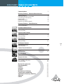
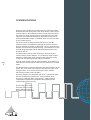
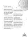
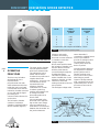
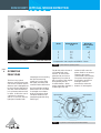
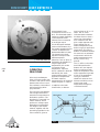
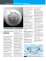
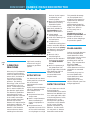
DISCOVERY ENGINEERING PRODUCT GUIDE
Ionisation Smoke Detector
Optical Smoke Detector
Temperature Detector
Multisensor Detector
Manual Call Point
Discovery® is a range of high-specification,
analogue addressable fire detectors
developed and manufactured by
Apollo Fire Detectors Limited.
Designed to meet specifications for detectors
incorporated in sophisticated systems, Discovery
provides engineers with an additional dimension
in fire protection capability.
In view of some of the advanced features
of Discovery, we recommend that engineers
familiarise themselves thoroughly with the range
by reading this product guide carefully.
In addition to the familiar smoke (ionisation and
optical) and heat detectors, the Discovery range
features a multisensor detector. This incorporates
an optical smoke sensor and a heat sensor which
can operate independently or together, with
the analogue value being derived by means of
sophisticated algorithms. The multisensor detector
matches the strengths of both ionisation and
optical detectors, and can, in most installations
be used instead of an ionisation detector.
Information in this guide is given in good faith, but
Apollo Fire Detectors cannot be held responsible
for any omissions or errors. The company reserves
the right to change specifications of products at
any time and without prior notice.
Key features
• Rejection of transient
•
•
•
•
•
•
•
•
signals
Flashing LED option
Five response modes
for ease of optimisation
to changing environments
Drift compensation
to ensure constant
sensitivity
Four bytes of non-volatile
memory for user data
Alarm flag for fast alarm
reporting
Conventional alarm facility
during CIE processor fault
360° visibility in alarm
Compatible with XP95
systems
The Discovery range
• Ionisation smoke
•
•
•
•
•
detector
Optical smoke detector
Heat detector
Multisensor detector
CO detector
Manual call point
DISCOVERY TABLE OF CONTENTS
Communications
2
Discovery Features – Smoke and Heat Detectors
Response setting
User bytes and other stored data
Conventional alarm facility
Flashing LED
Remote test feature
Rejection of transient signals
3
3
4
4
4
4
Discovery Features – Smoke Detectors
Drift compensation
5
Ionisation Smoke Detector
Operating principles
Technical data
6
7
Optical Smoke Detector
Operating principles
Technical data
8
9
Heat Detector
Operating principles
Technical data
10
11
Multisensor Detector
Operating principles
Technical data
12
13
Carbon Monoxide Detector
Operating principles
Technical data
14
16
Mounting Bases
Technical description
17
Manual Call Point
Operating principles
Non-standard call points
Technical data
18
18
19
Mechanical construction
Interchangeability
Isolators
Interfaces
Sounders
Maintenance of detectors
Control panel compatibility
Application of Discovery Detectors
Approvals
Patents
20
20
20
20
20
20
20
21
22
22
page
1
COMMUNICATIONS
Discovery uses a digital communications protocol which has been
developed from the XP95 protocol but which differs in that it allows
communication in three different modes: Normal, Read and Write.
The reason for developing the protocol is that the Discovery range
requires a more extensive exchange of information than previous
analogue addressable ranges. In addition, Discovery can store data
in non-volatile memory.
The Normal mode is identical to the XP95 protocol with the
exception that the five additional analogue value bits in the XP95
protocol extension have been re-defined for use as a mode selection
indicator (four bits) and a drift warning flag. This enables the control
and indicating equipment (CIE) to distinguish between Discovery
and XP95 devices.
The Read mode is used to check information stored in the nonvolatile memory of each detector. It is accessed by using a simple
extension to the Normal mode communication method from the
control and indicating equipment (CIE) to the detector.
page
2
In Write mode the CIE is able to write information to the detector by
extending the communication method in the same way as in Read
mode.
The detector does not return its analogue value during Read or Write
modes, but, in the event of the detector calculating an alarm value
during this time, it can use the alarm flag and alarm address
mechanism to alert the CIE to its status.
Discovery detectors are compatible with XP95. It should be noted,
however, that Discovery features will not be available when
Discovery is used with XP95 control panels. Panels with drift
compensation algorithms should disable the algorithms when
communicating with Discovery.
For a full description of the
Discovery protocol, refer to
Apollo publication PP2027,
Discovery Protocol PIN Sheet.
DISCOVERY FEATURES –
SMOKE AND HEAT DETECTORS
Response setting
Each detector in the Discovery range can
operate in one of five response modes, any of
which can be selected from the control panel.
Each mode corresponds to a unique response
behaviour, which can be broadly related to
sensitivity to fire. Whatever the type of
detector, Mode 1 will give a higher sensitivity
to fire than Mode 5. The selection of the most
suitable mode depends on the application.
Guidance on detector and mode selection is
given on pages 21-23.
For ionisation and optical smoke detectors,
the modes relate to different combinations of
smoke response threshold and response time.
For the heat detector, the mode relates to the
fixed temperature setting and the sensitivity to
rate-of-rise of temperature. For the
multisensor, the mode relates to the levels of
smoke and heat sensitivity and to the way in
which the responses of the two sensors are
combined.
irrespective of the response mode selected.
Similarly, the alarm flag in the protocol is
always set when the analogue value exceeds
55, irrespective of mode. This simplifies the
switching between response modes since the
alarm threshold in the control panel can
remain fixed at 55 and the alarm flag is valid
in all modes.
The response mode, which is selected
through the protocol, is stored in non-volatile
memory and will therefore be retained when
the detector is powered down. All Discovery
detectors are factory set to mode 3 before
shipping.
Response modes are defined more fully in the
individual detector descriptions.
User bytes and other stored data
All Discovery devices contain non-volatile
memory, in the form of Electrically Erasable
Programmable Read Only Memory
(EEPROM), which is included primarily to
The response characteristics of the detectors
store data needed for the correct operation of
have been carefully set so that detectors will
comply with the requirements of the relevant the device. However, four bytes of this
EEPROM are available to the user and can be
part of EN54 in all response modes. The
accessed by the control panel through the
mathematical algorithms embedded in the
protocol. This block of non-volatile memory
detectors are used to carry out changes in
can be used, for example, to store the
characteristics between modes. Since the
installation date, the site code or date of last
response characteristics are defined within
service. The only restriction on use is that the
the detectors, Apollo takes responsibility for
compliance with standards in different response maximum number of write cycles should not
exceed 20,000 over the life of the device.
modes.
The internal signal processing of the detectors
is designed so that the analogue value
reported is always close to 25 for a normal
condition. The alarm threshold is 55,
The way in which this memory can be
accessed is described in the Discovery
Protocol PIN Sheet PP2027.
page
3
Conventional alarm facility
Discovery devices should be polled at regular
intervals to maintain communication with the
control panel and therefore enable correct
monitoring of the protected premises.
However, if the polling mechanism fails, for
example because of a processor failure in the
panel, the internal operation of the Discovery
device will be unaffected as long as a DC
supply is maintained. After 108± 4 seconds
without protocol, the device will
automatically switch to its conventional alarm
mode. In this mode it will operate as if it were
a conventional detector (or manual call point)
and will impose an alarm signal on the loop if
an alarm condition is detected by the internal
processing.
The alarm signal takes the form of periodic
current pulses, which can be detected by
simple hardware in the control panel. A full
description of the signal can be found in the
Discovery Protocol PIN Sheet PP2027.
page
4
an alarm condition. After a delay of
approximately 10 seconds due to signal
processing, an analogue value of between 54
and 120 – nominally 85 – is returned,
provided that the detector is functioning
correctly. This value is sustained until the
forward command bit is changed back to its
original state, after which a period of 40
seconds is required for the detector to return
to its normal analogue value.
The manual call point is different in that the
receipt of the command bit will cause the call
point to generate the interrupt sequence,
followed by a sustained value of 64. The call
point resets when the forward command bit is
changed back to its original state. For further
details of this function, see Discovery Protocol
PIN Sheet, PP2027.
Rejection of transient signals
All Discovery detector algorithms are
designed to give low sensitivity to very rapid
changes in the sensor output, since these are
Flashing LED
unlikely to be caused by real fire conditions.
All Discovery detectors have two integral LED This is achieved by digital low-pass filtering
indicators, which can be illuminated at any
of the sensor values which optimises the
time by the control panel to indicate devices
rejection of false alarm sources while
in alarm. When activated, the LEDs will draw maintaining the response to fire.
an extra 3mA from the loop. In addition to
this mode of operation it is possible to enable The filter parameters depend on the mode
a flashing LED mode by writing to one of the selected and for some modes the filtering is
memory locations. In this mode the LEDs will minimal. The filtering has no significant effect
flash each time the device is polled. The
on the response to fires but does affect the
device does not draw extra current in this
way in which detectors respond to transients
mode since the LED current is part of the
and to step changes of smoke or heat. This is
normal current pulse reply from the device.
seen in the “minimum time to alarm” given in
This facility is available on all Discovery
detectors and the manual call point.
Discovery detectors and call points are
factory set to non-flashing mode.
Remote test feature
This feature, available on all Discovery
detectors and the call point, is enabled from
the CIE by changing the state of a forward
command bit. On receipt of the command
the detector is forced by electrical means into
individual detector specifications. These times
represent the time taken by the detector to
reach the alarm condition when responding
to a large step change in input.
Servicing Note
The “minimum time to alarm” referred to
above is important when detectors are
tested in situ, for example using aerosol
test gas. A delay in response may be
apparent.
DISCOVERY FEATURES –
SMOKE DETECTORS
Drift compensation
All Discovery smoke detectors include
compensation for sensor drift as part of the
internal signal-processing algorithm. The
algorithm will compensate for changes in
sensor output caused, for example, by dust in
the chamber, and will therefore hold the
sensitivity at a constant level even with
severe chamber contamination. This
increased stability is achieved without
significantly affecting the detector’s
sensitivity to fire.
The compensation level is stored in the
detector’s memory as a single value between
0 and 31. The normal level, that is, with no
compensation applied, is 16. Values above
or below this indicate drift towards alarm or
away from alarm respectively.
For compensation values in the range 4 to 30
the detector is working within its allowable
range. A value which is less than 4 or greater
than 30 results in a warning flag. A value of
zero results in a fault signal.
Fig.1
Drift Compensation Graph
The maximum compensation that can be
applied is 31. If further drift occurs, the
analogue values will simply track the drift
and the detector will become more sensitive.
Compensation values are stored in nonvolatile memory and will be retained even if
detectors are disconnected. It is possible to
use the control panel to ascertain the level of
compensation applied at any time.
For the Discovery smoke detectors, the
compensation algorithms are designed such
that the detectors meet the requirements of
the European draft standard EN54–7:2000 in
all response modes.
It is possible, through the protocol, to carry
out a normalisation procedure which rapidly
“updates” the drift compensation. This
facility may be useful during commissioning
when detectors can be quickly acclimatised
to the prevailing ambient conditions, or after
a compensated detector has been cleaned.
page
5
DISCOVERY IONISATION SMOKE DETECTOR
Mode
Alarm
threshold
y value
Minimum time
to alarm
(sec)
1
2
3
4
5
0.45
0.45
0.70
0.70
1.0
5
30
5
30
5
Compensation rate complies with EN54–7:2000
Table 1
Discovery Ionisation Smoke Detector
page
6
OPERATING
PRINCIPLES
The Discovery ionisation
smoke detector has a
moulded white
polycarbonate case with
wind-resistant smoke inlets.
Inside the case is a printed
circuit board which has the
ionisation chamber mounted
on one side and the signal
processing and
communications electronics
on the other.
The ionisation chamber
consists of a reference
chamber contained inside a
smoke chamber (Figure 2).
▲ Part Number 58000-500
The outer smoke chamber
has inlet apertures fitted
with insect resistant mesh.
The radioactive source
holder and the smoke
chamber form positive and
negative electrodes
respectively. An Americium
241 radioactive source
mounted within the
reference chamber
irradiates the air in both
chambers, producing
positive and negative ions.
A voltage across the
electrodes produces an
electric field.
Ions are attracted to the
electrode of the opposite
sign to their own charge;
many recombine but a
small electric current flows
between the electrodes. At
the junction between
Ionisation detector operating modes
reference and smoke
chambers, the sensing
electrode converts variations
in chamber current into
voltage changes.
When smoke particles enter
the ionisation chamber, ions
become attached to them
with the result that the
current flowing through the
chamber decreases.
This effect is greater in the
smoke chamber than in the
reference chamber, and the
imbalance causes the
sensing electrode to become
more positive.
The analogue voltage at the
Address Buttons
sensor electrode is
converted to a digital format
which is processed to
provide an analogue value
for transmission to the
control panel when the
device is polled.
Ionisation smoke detectors
are supplied in individual
packing with a red lid
serving as a dust cover
which can be left in place
after fitting to prevent
ingress of foreign material
until commissioning of the
system takes place. At this
point the covers must be
removed.
10V on Foil Holder
Case Moulding
Radioactive Foil
Lid Moulding
PCB
LED
LED
Inner Cover
Fig.2
Inner Chamber
0V
Smoke Chamber
Sectional view - Discovery Ionisation Smoke Detector
TECHNICAL DATA
Discovery Ionisation Smoke
Detector
Part No 58000-500
Specifications are typical at
24V, 23°C and 50% relative
humidity unless otherwise
stated.
Detection principle:
Ionisation chamber
Chamber configuration:
Twin compensating
chambers using one single
sided ionising radiation
source
Terminal functions:
L1 & L2 supply in and out
connections
+R
remote indicator
positive connection
(internal 2.2kΩ
resistance to
positive)
–R
remote indicator
negative connection
(internal 2.2kΩ
resistance to
negative)
Operating voltage:
17–28V DC
Communication protocol:
Apollo Discovery 5–9V
peak to peak
Clean-air analogue value:
23 +4/–0
Alarm level analogue value:
55
Alarm indicator:
2 red Light Emitting Diodes
(LEDs). Optional remote LED
Electro-magnetic
compatibility:
marked
A copy of the relevant
declaration is available on
request
Temperature range:
Max. continuous
operating
+60°C
Min. continuous
operating
0° C
–20°C
Min. operating
(no condensation/icing)
–30°C to +80°C
Storage
Radioactive isotope:
Americium 241
Quiescent current:
500µA average 750µA peak
Activity:
33.3 kBq, 0.9µCi
Power-up surge current:
1mA
Type code:
Bits 2 1 0 4 3 7 6 5
01100 000
Maximum power-up time:
10s
Humidity:
0 to 95% relative humidity
(no condensation)
Alarm current, LED
illuminated:
3.5mA
Effect of temperature:
Less than 10% change in
sensitivity over rated range
Supply wiring:
Two-wire supply, polarity
insensitive
Remote output
characteristics:
Connects to positive line
through 4.5kΩ (5mA
maximum)
SAFETY NOTE
In the United Kingdom,
ionisation smoke detectors
are subject to the
requirements of the
Radioactive Substances Act
1960 and to the Ionising
Radiations Regulations
1985 made under the
provisions of the Health and
Safety at Work Act 1974.
The detectors,
independently tested by the
National Radiological
Protection Board (NRPB),
conform to all the
requirements specified in
the ‘Recommendations for
ionisation smoke detectors
in implementation of
radiation standards’
published by the Nuclear
Energy Agency of the
Organisation for Economic
Co-operation and
Development (OECD) 1977.
There is no limit to the
number of ionisation smoke
detectors which may be
installed in any fire
protection system.
Storage regulations depend
on local standards and
legislation, but, in the UK,
up to 500 detectors may be
stored in any premises,
although there are
stipulations on storage
facilities if more than 100
ionisation detectors are
stored in one building.
At the end of their
recommended working life
of ten years, ionisation
smoke detectors should be
returned to Apollo for safe
disposal or disposed of in an
otherwise locally approved
and environmentally safe
manner. Please see
"A guide to the care,
maintenance and servicing
of Apollo products",
PP2055.
Effect of atmospheric
pressure:
Less than 15% change in
sensitivity up to 2000m
Effect of wind:
Less than 20% change in
sensitivity at speeds up to
10m/s.
Note: slow changes in
ambient conditions will
automatically be compensated
and will not affect sensitivity
Vibration, Impact and
Shock:
To EN54–7:2000
IP rating:
43
Dimensions:
100mm diameter;
42mm height
50mm (height in base)
Weight:
Detector
Detector in base
105g
160g
Materials:
Housing: White
polycarbonate V–0 rated to
UL94
Terminals: Nickel plated
stainless steel
Guidance on storage and
handling can be given by
Apollo Fire Detectors and
full details can be requested
from:
Radioactive Substances
Regulation Function
Environment Agency
Rio House, Waterside Drive
Aztec West, Almondsbury
Bristol BS32 4UD.
Outside the UK, please
contact the relevant
national agency.
page
7
DISCOVERY OPTICAL SMOKE DETECTOR
Discovery Optical Smoke Detector
▲ Part Number 58000-600
Mode
Alarm threshold
%/m
1
2
3
4
5
1.4
1.4
2.1
2.1
2.8
OPERATING
PRINCIPLES
The Discovery optical
detector uses the same outer
case as the ionisation smoke
detector and is distinguished
by the indicator LEDs which
are clear when the detector
is in quiescent state and red
in alarm. Within the case is
a printed circuit board
which, on one side, has the
light-proof chamber with
integral gauze surrounding
the optical measuring
system and, on the other,
the signal processing and
communications electronics.
An infra-red light emitting
diode within its collimator
is arranged at an obtuse
angle to the photo-diode.
The photo-diode has an
integral daylight-blocking
filter (Fig.3).
5
30
5
30
5
Compensation rate complies with EN54–7:2000
Table 2
page
8
Minimum
time to alarm
(sec)
Optical detector operating modes
The IR LED emits a burst of
collimated light every
second. In clear air the
photo-diode receives no
light directly from the IR
LED, because of the angular
arrangement and the
chamber baffles. When
smoke enters the chamber it
scatters light from the
Optical Chamber
PCB Cover
Case Moulding
Fig.3
emitter IR LED onto the
photo-diode in an amount
related to the smoke
characteristics and density.
The photo-diode signal is
processed to provide an
analogue value for
transmission when the
detector is interrogated.
Address Buttons
Photo-Diode
Infra-Red LED
Top section - Discovery Optical Smoke Detector
TECHNICAL DATA
Discovery Optical Smoke
Detector
Part No: 58000-600
Specifications are typical
at 24V, 23°C and 50%
relative humidity unless
otherwise stated.
Detection principle:
Photo-electric detection of
light scattered in a forward
direction by smoke particles
Chamber configuration:
Horizontal optical bench
housing infra-red emitter and
sensor, arranged radially to
detect forward scattered light
Sensor:
Silicon PIN photo-diode
Emitter:
GaAlAs infra-red light
emitting diode
Sampling frequency:
1 per second
Type code:
Bits 2 1 0 4 3 7 6 5
10100 000
Supply wiring:
Two-wire supply, polarity
insensitive
Terminal functions:
L1 & L2 supply in and out
connections
+R
remote indicator
positive connection
(internal 2.2kΩ
resistance to
positive)
–R
remote indicator
negative connection
(internal 2.2kΩ
resistance to
negative)
Operating voltage:
17–28V DC
Communication protocol:
Apollo Discovery 5–9V
peak to peak
Quiescent current:
400µA average 650µA peak
Power-up surge current:
1mA
Maximum power-up time:
10s
Alarm current, LED
illuminated:
3.4mA
Remote output
characteristics:
Connects to positive line
through 4.5Ω (5mA
maximum)
Clean-air analogue value:
23 +4/–0
Alarm level analogue value:
55
Alarm indicator:
2 colourless Light Emitting
Diodes (LEDs); illuminating
red in alarm. Optional
remote LED
Electro-magnetic
compatibility:
marked
A copy of the relevant
declaration is available on
request
Temperature range:
Max. continuous
operating
+60°C
Min. continuous
operating
0°C
Min. operating
–20°C
(no condensation/icing)
Storage
–30°C to +80°C
Humidity:
0 to 95% relative humidity
(no condensation)
Effect of temperature:
Less than 15% change in
sensitivity over rated range.
Note: slow changes in
ambient conditions will
automatically be compensated
and will not affect sensitivity
Effect of atmospheric
pressure:
None
Effect of wind:
None
Vibration, Impact and
Shock:
To EN54–5:2000
IP rating:
43
Dimensions:
100mm diameter;
42mm height
50mm (height in base)
Weight:
Detector
Detector in base
105g
160g
Materials:
Housing: White
polycarbonate V–0 rated
to UL94
Terminals: Nickel plated
stainless steel
page
9
DISCOVERY HEAT DETECTOR
approximately linear
characteristic from 10°C to
80°C. This linearised signal is
further processed, depending
on the response mode
selected, and converted to
an analogue output.
Discovery Heat Detector
page
10
may be given an “R” or “S”
suffix. The “R” suffix
indicates that the detector
has been shown to have a
rate-of-rise characteristic.
Such a detector will still
give a rapid response even
when starting from an
ambient temperature well
below its typical application
temperature. This type of
detector is therefore suitable
for areas such as unheated
warehouses in which the
ambient temperature may
be very low for long
periods.
For the European standard
version of the detector, the
five modes correspond to five
“classes” as defined in the
draft standard EN54–5:2000.
The classes in this draft
standard correspond with
different response
▲ Part Number 58000-400 behaviour, each of which is
designed to be suitable for a
range of application
temperatures. All modes
incorporate “fixed
temperature” response,
OPERATING
which is defined in the draft
PRINCIPLES
standard by the “static
response temperature”. The
application temperatures
Discovery heat detectors
and static response
have a common profile with
temperatures for all response
ionisation and optical smoke
modes are given in Table 3.
detectors but have a low air
flow resistance case made of In addition to the basic
classification, a detector
self-extinguishing white
polycarbonate.
The Discovery heat detector
uses a single thermistor to
sense the air temperature at
the detector position. The
thermistor is connected in a
resistor network, which
produces a voltage output
dependent on temperature.
The design of the resistor
network, together with the
processing algorithm in the
microcontroller, gives an
Address Buttons
The “S” suffix on the other
hand indicates that the
detector will not respond
below its minimum static
response temperature even
when exposed to high rates
of rise of air temperature.
This type is therefore
suitable for areas such as
kitchens and boiler rooms
where large, rapid
temperature changes are
considered normal.
Thermistor Bead
PCB
Lid Moulding
LED
LED
Heat Shrink Sleeving
Fig.4
Case Moulding
Discovery Heat Detector
TECHNICAL DATA
Operating voltage:
17–28V DC
Discovery Heat Detector
Part No: 58000-400
Communication protocol:
Apollo Discovery 5–9V peak
to peak
Specifications are typical at
24V, 23°C and 50% relative
humidity unless otherwise
stated.
Detection principle:
Temperature sensitive resistance.
Type code:
21043 765
11000 000
Supply wiring:
Two-wire supply, polarity
insensitive
Terminal functions:
L1 & L2 supply in and out
connections
+R
remote indicator
positive connection
(internal 2.2kΩ
resistance to positive)
–R
remote indicator
negative connection
(internal 2.2kΩ
resistance to
negative)
Mode
Quiescent current:
500µA average 750µA peak
Power-up surge current:
1mA
Maximum power-up time:
10s
Alarm current, LED
illuminated:
3.4mA
Remote output
characteristics:
Connects to positive line
through 4.5kΩ (5mA
maximum)
Alarm level analogue value:
55
Class
(EN54–5:2000)
Alarm indicator:
2 red Light Emitting Diodes
(LEDs).
Optional remote LED
Electro-magnetic
compatibility:
marked
A copy of the relevant
declaration is available on
request
Temperature range:
Max. continuous
operating see Table 3
Min. continuous
operating
0°C
–20°C
Min. operating
(no condensation/icing)
–30°C to +80°C
Storage
Heat Detector response modes
Dimensions:
100mm diameter; 42mm
height
Weight:
Detector
Detector in base
105g
160g
Materials:
Housing: White
polycarbonate V–0 rated
to UL94
Terminals: Nickel plated
stainless steel
Humidity:
0 to 95% relative humidity
(no condensation)
Vibration, Impact and
Shock:
To EN54–5:2000
page
11
Application
Temperature °C
Typ
Max
Static Response
Temperature °C
Min
Typ
Max
1
A1R
25
50
54
57
65
2
A2
25
50
54
61
70
3
A2S
25
50
54
61
70
4
CR
55
80
84
90
100
5
CS
55
80
84
90
100
For air temperatures in the range 15°C to 55°C, the analogue value for a detector in
mode 1 will correspond approximately to the air temperature.
Table 3
IP rating:
53
DISCOVERY MULTISENSOR DETECTOR
without the presence of smoke,
if sustained for 20 seconds.
The processing algorithms in
modes 1 to 4 incorporate
drift compensation.
The characteristics of the
five response modes are
summarised below.
Mode 1 has very high smoke
sensitivity combined with
high temperature sensitivity.
This gives a high overall
sensitivity to both smouldering
and flaming fires.
Discovery Multisensor Detector
page
12
OPERATING
PRINCIPLES
The Discovery multisensor
detector contains an optical
smoke sensor and a
thermistor temperature
sensor whose outputs are
combined to give the final
analogue value. The way in
which the signals from the
two sensors are combined
depends on the response
mode selected. The five
modes provide response
behaviour which incorporates
pure heat detection, pure
smoke detection and a
combination of both. The
multisensor is therefore
useful over the widest range
of applications.
The multisensor construction
is similar to that of the
optical detector but uses a
different lid and optical
mouldings to accommodate
▲ Part Number 58000-700
the thermistor temperature
sensor. The sectional view
(Fig 5) shows the
arrangement of the optical
chamber and the thermistor.
The signals from the optical
smoke sensing element and
the temperature sensor are
independent, and represent
the smoke level and the air
temperature respectively in
the vicinity of the detector.
The detector’s microcontroller processes the two
signals according to the
mode selected. When the
detector is operating as a
multisensor (i.e. modes 1, 3
and 4) the temperature
signal processing extracts
only rate-of-rise information
for combination with the
optical signal. In these
modes the detector will not
respond to a slow
temperature increase – even
if the temperature reaches a
high level. A large sudden
change in temperature can,
however, cause an alarm
Mode 2 has a smoke
sensitivity similar to that of a
normal optical smoke
detector but has no response
to temperature. This mode is
therefore equivalent to a
standard optical detector. It
is suitable for applications in
which wide temperature
changes occur under normal
conditions.
which a certain amount of
fumes or smoke is
considered normal.
Mode 5 has no smoke
sensitivity at all, but gives a
pure heat detector response
meeting the response time
requirements for a Class A1
detector in the draft European
standard EN54–5:2000. In
this mode the detector will
respond to slowly changing
temperatures and has a
“fixed temperature” alarm
threshold at 58°C. The
analogue value in this mode
will give the approximate
air temperature over the
range 15°C to 55°C.
In mode 5, the smoke sensor
is still active though it does
not contribute to the analogue
signal. As a consequence, if
the detector is used in a
dirty or smoky environment
the optical sensor drift flag
Mode 3 has moderate smoke may be activated in the
heat-only mode.
sensitivity combined with a
moderate sensitivity to heat. Note: in situ testing of the
This combination is
multisensor detector should
considered the optimum for be carried out as for smoke
most general applications
detectors in response modes
since it offers good response 1-4 and for heat detectors in
to both smouldering and
response modes 5.
flaming fires.
Design Note: if the
Mode 4 has lower than
multisensor is to be used in
normal smoke sensitivity
mode 5, heat detector
combined with high heat
spacing/coverage should be
sensitivity. This makes it
applied.
suitable for applications in
Twin Alarm LEDs
PCB
RFI Shield
Chamber cut
away to reveal
optical bench
External
moulding
Optical chamber
Fig.5
Thermistor
Sectional view - Discovery Multisensor Detector
TECHNICAL DATA
Discovery Multisensor
Detector,
Part No 58000-700
Specifications are typical
and apply at temperature
23°C and relative humidity
50% unless otherwise
stated.
Detector principle:
Smoke: Photoelectric
detection of light scattered
by smoke particles
Heat: Temperature-sensitive
resistance
Type code:
Bits 2 1 0 4 3 7 6 5
10111 000
Supply wiring:
Two-wire supply, polarity
insensitive
Terminal functions:
L1 & L2 supply in and out
connections
+R
remote indicator
positive connection
(internal 2.2kΩ
resistance to positive)
–R
remote indicator
negative connection
(internal 2.2kΩ
resistance to
negative)
Mode
1
2
3
4
5
Table 4
Operating voltage:
17–28V DC
Communication protocol:
Apollo Discovery 5–9V peak
to peak
Quiescent current:
500µA average 750µA peak
Power-up surge current:
1mA
Maximum power-up time:
10s
Alarm current, LED
illuminated:
3.5mA
Remote output
characteristics:
Connects to positive line
through 4.5kΩ (5mA
maximum)
Clean-air analogue value:
23 +4/–0
Alarm level analogue value:
55
Alarm indicator:
2 colourless Light Emitting
Diodes (LEDs); illuminated
red in alarm
Optional remote LED
Electro-magnetic
compatibility:
marked
A copy of the relevant
declaration is available on
request
Temperature range:
Max. continuous
operating
+60°C
Min. continuous
operating
0°C
–20°C
Min. operating
(no condensation/icing)
–30°C to +80°C
Storage
Humidity:
0 to 95% relative humidity
(no condensation)
Effect of temperature on
optical sensor:
Less than 15% change in
sensitivity over rated range.
Slow changes in ambient
conditions will automatically
be compensated and will not
affect sensitivity
Effect of atmospheric
pressure on optical sensor:
None
Effect of wind on optical
sensor:
None
Multisensor Detector operating modes
Dimensions:
100mm diameter;
50mm height
58mm (height in base)
Weight:
Detector
Detector in base
High
No response to heat
Low
High
See text
105g
160g
Materials:
Housing: White
polycarbonate V–0 rated to
UL94
Terminals: Nickel plated
stainless steel
Smoke element only:
Chamber configuration:
Horizontal optical bench
housing infra-red emitter
and sensor, arranged
radially to detect forward
scattered light
Sensor:
Silicon PIN photo-diode
Emitter:
GaAlAs infra-red light
emitting diode
Sampling frequency:
1 per second
Vibration, Impact and
Shock:
To EN54–7:2000
Smoke Sensitivity
Temperature Sensitivity
(grey smoke)
(relative)
% per m
% per ft
1.1
0.35
2.1
0.7
2.8
0.9
4.2
1.4
No response to smoke
IP rating:
43
Response Type
Minimum Time to
Alarm (seconds)
Multisensor
Optical
Multisensor
Multisensor
Heat A1
20
30
20
20
30
page
13
DISCOVERY CARBON MONOXIDE DETECTOR
levels of alcohol vapour
as emitted by some
cleaning agents
there is a requirement to
detect fires involving
flammable liquids
CO fire detectors are
particularly suitable for
supplementing smoke
detection when there is:
■ a deep seated
smouldering fire risk
■ a risk of fire starting in an
enclosed space
■ a likelihood of
stratification taking place
Carbon monoxide detectors
may be used as the primary
fire detector in areas where
the following conditions
exist:
■ the main risk is
smouldering fires
■ optical smoke detectors
are deemed unsuitable
(see ‘FALSE ALARMS’
below)
■ the fire compartment is
not greater than 50m2
Typical applications include
hotel bedrooms, halls of
residence, sheltered
accommodation and
hospital wards.
■
Discovery Carbon Monoxide Detector
page
14
OPERATING
PRINCIPLES
Discovery CO fire detectors
contain a long-life electrochemical carbon monoxide
sensor which is tolerant of
low levels of common
vapours and household
products. The sensing
technology is fast, accurate
and needs only very low
power. These factors make
the CO sensor suitable for
fire detection applications.
The detection capabilities
are enhanced by a ratesensitive response. Fast rises
in the carbon monoxide
level are often associated
with hot fires and the
detector will respond earlier
under these conditions. The
analogue reply from the
detector is rate limited to
remove nuisance alarms
resulting from short-term
▲ Part Number 58000-300
high levels caused by
sources such as pipe
smokers or gas flame
ignition.
APPLICATION
CO detectors do not detect
smoke particles or heat and
are not universal
replacements for smoke
detectors.
Apollo does not endorse the
use of CO detectors as the
main method of fire
detection if:
■ the protected area is an
escape route
■ there is a requirement to
detect overheating of
electrical equipment or
cables
■ the protected area is
exposed to sources of CO
such as vehicle exhausts,
or to hydrogen or to high
DETECTOR SITING
CO fire detectors should
be sited using the
recommendations for smoke
detectors from BS5839: Part
1 (or other applicable code).
In the development of a fire,
smoke and CO in the
smoke plume is spread by
convection to a fire detector.
As CO is a gas, it further
spreads—like smells—by
diffusion. For this reason
CO may reach a detector
faster than smoke would.
This potential advantage
can be exploited when
designing a fire protection
system and CO detectors
may be used for
supplementary detection.
Equally, the opposite effect
might occur, with CO
moving away from a
detector.
The behaviour of CO is
therefore unpredictable and
diffusion should not be
relied on when designing a
fire protection system.
FALSE ALARMS
Carbon monoxide detectors
are less susceptible than
smoke detectors to false
alarms from sources such as
toast, steam, cooking,
plumbing work and hair
spray. They may therefore
be used in some
applications in which
smoke detectors would be
susceptible to unwanted
alarms.
Conversely, they may be
more susceptible than
smoke detectors to false
alarms from fumes
containing CO, such as
vehicle exhausts, open fires
and gas appliances.
LIMITATIONS
CELL TEST
Carbon monoxide detectors
also have important
limitations. They are set to
a higher sensitivity than the
maximum allowed by the
domestic CO alarm
standard and will respond
to CO from faulty gas
appliances or vehicle
exhausts. These detectors
should not be used in place
of carbon monoxide alarms
complying with BS7860 or
UL2034.
The Discovery carbon
monoxide fire detector has
a remote test feature, which
is used to verify that the
electro-chemical cell is fitted
and that it is active. A test
must be carried out at least
once a year but preferably
more frequently to ensure
that the cell has not dried
out. (Note that the cell will
not be affected by the test,
even if the remote test is
carried out once a day.)
If the test indicates a sensor
failure, ie, the detector returns
a pre-set analogue value of 25,
the detector should be sent to
Apollo’s Service Department
for cell replacement and
detector recalibration.
OPERATING
MODES
The Discovery CO detector
has five operating modes,
each having a set
combination of sensitivity
and response delay, which
the user can select for any
given application. See table
on page 16.
DRIFT
COMPENSATION
In view of the inherent
stability of CO cells, there is
no need for Discovery CO
detectors to compensate for
drift. Discovery CO
detectors are set to report a
drift value of 16.
PRECAUTIONS
WHEN
INVESTIGATING
ALARMS
It is important to remember
that CO is a colourless,
odourless gas, which is not
directly detectable by
human senses. If a CO fire
detector is in an alarm
condition, it is possible that
a dangerous level of CO
exists around the detector.
Extreme care must be taken
when investigating alarms
from CO fire detectors even
if no combustion products
can be seen or smelled.
Because of this danger, it is
imperative that CO fire
detectors are correctly
identified at the control
panel so that personnel
investigating alarms may take
the relevant precautions.
MAINTENANCE
AND SERVICE
The electrochemical cell
used in the Discovery CO
fire detector has a more
limited life than would
normally be expected from
a smoke detector. In a
typical environment, the life
of the cell is seven years.
High temperature or low
relative humidity can,
however, reduce the life
significantly. The limits
given in the section
‘technical data’ overleaf
should be carefully
observed.
It is essential that systems
using CO fire detectors be
correctly maintained and
that the maintenance
schedule include functional
testing of the CO fire
detectors.
CO fire detectors will not
respond to the aerosol
testers commonly used for
the in-situ testing of smoke
detectors. Apollo
recommends that CO fire
detectors be tested using a
“hand warmer”, burning
compressed charcoal fuel
rods. These hand warmers
are available in camping
and outdoor shops. The
charcoal rod should be
ignited at one end
according to the
instructions. To achieve a
reliable test, the complete
hand warmer should be
placed inside a hood which
fits over the detector,
allowing CO to build up
around the detector. The
Apollo (No Climb) detector
tester can be used for this
purpose.
If there is any doubt over
the sensitivity of a
Discovery CO fire detector
it should be returned to
Apollo for servicing and
calibration.
HEALTH AND
SAFETY
GUIDELINES
This product contains a
sealed electro-chemical cell
and in normal usage
represents no chemical
hazard in the sense of
COSHH and the Health and
Safety at Work Act 1974.
Chemical hazard can,
however, arise if the
following notes on storage,
handling and disposal are
not observed.
For maximum life, the
product should be stored
before installation in clean
dry conditions between 0°C
and 20°C. It should not be
exposed to temperatures
outside the range –40°C to
+60°C or to organic
vapours.
The electrochemical cell
contained in this product is
fitted into sockets on the
printed circuit board; to
avoid damage to the cell do
not remove it.
The electrochemical cell
contains sulphuric acid in a
relatively concentrated
state. In the event of
leakage (which may be
caused by mechanical
damage or use outside the
operating specification for
the cell) the cell should be
removed from the detector
using protective gloves.
Avoid contact with any
liquid. If skin or eye
contact with the electrolyte
occurs, wash immediately
with plenty of water and
page
15
TECHNICAL DATA
Discovery Carbon
Monoxide Fire Detector
Communication protocol:
Apollo Discovery 5–V
peak to peak
Specifications are typical
and apply at 24V, 23˚C
and 50% relative humidity
unless otherwise stated.
Quiescent current:
500µA average, 750µA
peak
Detector Part no:
58000-300
Power-up surge current:
1mA
Alarm indicator:
2 red Light Emitting Diodes
(LEDs);
Optional remote LED
Effect of temperature on
detector:
Less than 15% change in
sensitivity over rated range
Electro-magnetic
compatibility:
marked
Effect of wind:
None
Storage Temperature:
Continuous: +10˚C to +30˚C
Transient: –40˚C to +55˚C
Storage Pressure:
If air freighted this product
should be placed in a
pressurised hold
Base Part no:
45681-210
Maximum power-up time:
10s
Detector principle:
Ambient carbon monoxide
level
Alarm current, LED
illuminated:
3.5mA
Type code:
Bits 2 1 0 4 3 7 6 5
0 1 1 0 1 0 0 1
Remote output
characteristics:
Connects to positive line
through 4.5kΩ (5mA
maximum)
Operating Temperature:
Continuous: 0˚C to +50˚C
Transient: –20˚C to +50˚C
(no condensation/icing)
Sampling frequency:
1 per second
Operating Humidity:
Continuous: 15% to 90% RH
Transient: 0% to 99% RH
Supply wiring:
Two-wire supply, polarity
sensitive
page
16
Operating voltage:
17–28V DC
Terminal functions:
L2
positive supply in
and out connections
L1
negative supply in
and out connections
+R
remote indicator
positive connection
(internal 2.2kΩ
resistance to positive)
–R
remote indicator
negative connection
(internal 2.2kΩ
resistance to
negative)
obtain medical advice. All
traces of electrolyte should
be washed away with
copious amounts of clean
Operating Pressure:
Atmospheric ±10%
Clean air analogue value:
25±2
Alarm level analogue value:
55
water. The cell should be
disposed of according to
local waste management
requirements and
Cell Life:
maximum 7 Years
(assumes regular checks
are satisfactory)
Vibration, Impact and
Shock:
To EN54–7:2000
IP rating:
43
Dimensions:
100mm diameter
42mm height
50mm (height in base)
Weight:
Detector 105g
Detector in base 160g
Materials:
Housing: White
polycarbonate,
V–0 rated to
UL94
Terminals: Nickel plated
stainless steel
environmental legislation.
It should not be burnt since
it may release toxic fumes.
Mode
Alarm Threshold
(ppm)
Minimum time to
alarm (seconds)
1
30
60
Sleeping with no ambient CO
2
45
30
General use fast response such as supplementary protection in atria
3
45
60
General use and sleeping risk with some low-level CO
(such as from light smoking or an unventilated gas fire)
4
60
30
General smoking area and supplementary detection of deep seated
fires such as laundry rooms
5
75
30
Supplementary use in kitchen or boiler room
Table 6
Relative performance of detectors in test fires
Typical application
DISCOVERY MOUNTING BASES
Discovery/XP95 Mounting Base
▲ Part Number 45681-210 with XPERT card
TECHNICAL
DESCRIPTION
All detectors in the
Discovery range fit into
XP95 mounting bases.
Full details of bases and
mounting accessories are
given in PP1089 and PIN
sheets PP2040 and 2043.
An earth connection is not
required for either safety or
correct operation of
detectors. The ground (earth)
terminal is isolated and is
provided for tidy termination
of grounded conductors or
cable screens and to
maintain earth continuity
where necessary.
All terminals are marked
according to their function.
Bases have a wide interior
diameter for ease of access
to cables and terminals and
there are two slots for fixing
screws. The slots enable two
fixing screws to be located
at a spacing of 51 to 69mm.
The bases are of 100mm diameter and have five
terminals:
L1
line in and line out
double terminal
L2
–R
line in and line out
double terminal
remote LED negative supply
double terminal
+R
remote LED positive supply
double terminal
earth
single terminal
E
Detectors fit into bases one
way only, without snagging,
and require clockwise
rotation without push force
to be plugged in.
Universal patented address
cards, known as XPERT
cards, are supplied with all
bases. Consult the coding
guide in the installation
instructions to determine
which pips are to be
removed from the card to
give the correct address. Lay
the card on a flat surface, pips
down, insert a screwdriver
into the slot on the reverse
of the pip to be removed
and give a firm twist.
When the card is coded
insert it into the slot in the
side of the appropriate base,
making sure that the card
locks itself into place. As a
detector is inserted into the
base, the remaining pips
operate the address buttons
on the detector and the
detector electronics reads
the address.
page
17
DISCOVERY MANUAL CALL POINT
point has only one response
mode. This is factory preset
to 16.
Discovery Manual Call Point (MCP)
page
18
▲ For Part Numbers see Table 5
OPERATING
PRINCIPLES
The Discovery call point is
based on the KAC World
Series.
The address of each call
point is set at the
commissioning stage by
means of a seven-segment
DIL switch.
If an MCP is activated it
interrupts the normal
protocol to give a fast
response. For full details of
the patented interrupt
feature, see publication
PP2027.
The Discovery call point has
4 bytes of non-volatile
memory available for the
user in the same way as
Discovery detectors. The
call point has the
conventional alarm facility.
The Discovery manual call
A single alarm LED is
provided on the call point.
This LED is controlled,
independently of the call
point, by the CIE and may
be set to flash each time the
call point is polled.
Call points can be remotely
tested from the control and
indicating equipment by
transmission of a single bit
in the communications
protocol. Call points
respond by providing an
analogue value of 64 which
corresponds to the alarm
value. The CIE should
recognise this response as a
test signal and should not
raise a general alarm.
NON-STANDARD
MANUAL CALL
POINTS
Manual call points approved
for use in countries applying
DIN standards are available,
as are XP95 manual call
points for outdoor use or for
special purposes, such as
initiating an ‘Evacuate’
alarm. It should be
remembered, however, that
XP95 manual call points
have no user bytes available
and do not have the
Discovery conventional
alarm facility.
The Discovery Manual Call Point is available in two versions:
Part no. 58000-910
For surface mounting, incorporating the call point
assembly and a back-box.
Part no. 58000-920
For flush mounting, incorporating the call point assembly
and a terminal tray.
For flush mounting an outlet (pattress) box with a
minimum depth of 25mm is also needed.
Table 5
Manual Call Point Part Numbers
TECHNICAL DATA
Manual Call Point
Specifications are typical
and apply at temperature
23°C and relative humidity
50% unless otherwise
stated.
Call point type:
Break glass
Part No 58000-910
surface mount assembly
Weight 190g
Part No 58000-920
flush mount assembly
Weight 180g
Part No 26729-107
back-box
Part No 26729-110
terminal tray
Call point principle:
Operation of a switch
Alarm indicator:
Red Light Emitting Diode
(LED)
Type code:
Bits 2 1 0 4 3 7 6 5
11111 000
Supply wiring:
Two-wire supply, polarity
insensitive
Loop connections L1/L2:
Flying leads with spade
terminals
Operating voltage:
17–28V DC
Communication protocol:
Apollo Discovery 5–9V
peak to peak
Quiescent current:
350µA average 600µA peak
Power-up surge current:
1mA
Maximum power-up time:
4s
Alarm current, LED
illuminated:
3.35mA
Normal analogue value:
16
Alarm state value:
64
Electro-magnetic
compatibility:
marked
A copy of the relevant
declaration is available on
request
Humidity:
0 to 95% relative humidity
(no condensation)
Vibration, Impact and
Shock:
To BS5839: Part 2
IP rating:
53
Dimensions:
87mm x 87mm x 52mm
(surface mount version)
Materials:
Housing: Red self-coloured
PC/ABS
Temperature range:
Max. continuous
operating
+60°C
Min. continuous
operating
0°C
–20°C
Min. operating
(no condensation/icing)
–30°C to +80°C
Storage
page
19
MECHANICAL
CONSTRUCTION
INTERCHANGEABILITY
All detectors in the
Discovery range have the
same external dimensions,
except the multisensor
detector, which is deeper.
The housing of the
ionisation and optical
smoke detectors is identical.
Any Discovery detector may
be replaced by any other
type in the range. For
example, if a smoke
detector proved unsuitable
in a particular application, it
could be simply replaced
with a heat detector set to
the appropriate grade or
range, provided that the
maximum floor area
coverage does not exceed
that specified by BS5839:
Part1 or other local code.
The material used to mould
the housings is a UL 94 V–0
grade of polycarbonate in a
pure white finish.
Two light-emitting diodes
(LEDs) are mounted on the
printed circuit board within
the housing. They protrude
through the lid to be easily
visible and provide external
alarm indication.
page
20
The LEDs of the ionisation
smoke detector and the heat
detector are red, and the
optical and multisensor
detectors have colourless
LEDs which emit red light in
the alarm state.
All detectors in the
Discovery range have four
nickel-plated stainless steel
wipers at the back of the
housing which make
contact with the double
terminals when the detector
is fitted to a base.
Discovery detectors can
also be used to replace
XP95 detectors and again, it
is possible to change types,
e.g. smoke for heat or vice
versa when mixing types.
Factory-new Discovery
detectors are set to mid
range, equivalent to XP95,
and the flashing LED feature
is disabled.
Note: the control and
indicating equipment must
not have a drift compensation
algorithm activated when
interrogating Discovery
detectors.
Some XP95 panels may not
recognise the multisensor or
CO detector type codes.
Contact the panel
manufacturer for advice.
ISOLATORS
All XP95 isolators and isolating bases are patented and are
suitable for use with Discovery detectors and manual call points.
These are:
Product
Part no
Literature
Isolating base 20D 45681–321 PIN sheet PP2039
Isolator
55000–700 Product guide PP1039
Base for isolator
45681–211 Product guide PP1039
INTERFACES
All XP95 interfaces are fully
compatible with Discovery
detectors and call points.
Please see the Interfaces
Brochure, PP2025, for
further information.
SOUNDERS
Loop sounders developed
for use with XP95 systems
may be used in exactly the
same way with Discovery.
See publication PP2031.
MAINTENANCE
OF DETECTORS
Apollo Fire Detectors has
published a guide to the
care, maintenance and
servicing of Apollo
products, PP2055, which
is available on request.
This guide outlines the
maintenance routines
recommended for optimum
detector performance and
the services available from
Apollo’s factory-based
Service Department.
CONTROL PANEL
COMPATIBILITY
Discovery detectors are
designed to be operated with
purpose-designed control
and indicating equipment
that makes full use of their
features. Discovery can,
however, be connected to
any control panel which can
operate existing ranges of
Apollo analogue addressable
detectors with the previously
noted rule, that the control
and indicating equipment
must not have a drift
algorithm operating on
Discovery devices. Contact
the panel manufacturer for
guidance. For a list of
compatible panel
manufacturers, see Apollo
publication PP1010.
DISCOVERY
APPLICATION OF
DISCOVERY DETECTORS
The process of designing a fire detection
system using Discovery detectors is the same
as that used for any other detector range,
except that Discovery offers more choices to
the system designer. The principles set out in
relevant codes of practice such as BS5839:
Part 1 should be followed in any system
design. The notes below are intended to
supplement the codes of practice and to give
some specific guidance on the choices
available with the Discovery range.
Choice of Detector Type
The choice of detector from
the Discovery range follows
the well-established
principles of system design.
That is, the optimum
detector type will depend on
the type of fire risk and fire
load, and the type of
environment in which the
detector is sited.
The multisensor is basically
an optical smoke detector
and will therefore respond
well to the smoke from
smouldering fires. In
response modes 1, 3 and 4,
however, (ie, in the
multisensor modes) the
detector also senses air
temperature. This
temperature sensitivity
For general use, smoke
allows the multisensor to
detectors are recommended
give a response to fast
since these give the highest
burning (flaming) fires which
level of protection. Smoke
is similar to that of an
detectors from the Discovery
ionisation detector. The
range may be ionisation,
multisensor can therefore be
optical or multisensor types.
used as an alternative to an
It is generally accepted that
ionisation detector while still
ionisation types have a high
retaining the benefits of an
sensitivity to flaming fires
optical smoke detector.
whereas optical detectors
Where the environment is
have high sensitivity to
smouldering fires. As a result smoky or dirty under normal
conditions, a heat detector
of this, ionisation types are
may be more appropriate. It
widely used for property
protection, and optical types must be recognised,
however, that any heat
for life protection. These
general principles still apply detector will respond only
when the fire is well
to the Discovery detectors,
although the availability of a established and generating a
multisensor in the Discovery high heat output. The
Discovery heat detector can
range offers more choice to
be used in a wide range of
the system designer.
Ionisation
Optical
Multisensor
Heat
CO
Poor
Very good
Very good
Very poor
Very poor
Moderate/Good
Good
Good
Very poor
Excellent
Flaming combustion
Very good
Good
Good
Poor
Poor
Flaming with high heat output
Very good
Good
Very good
Moderate/good
Moderate
Poor
Very poor
Moderate/good
Moderate/good
Very poor
Overheating/thermal decomposition
Smouldering/glowing combustion
Flaming – clean burning
Table 6
Relative performance of detectors in test fires
page
21
conditions by selecting the
correct mode (see Table 7).
The relative performance of
the four detector types for
different fire types is given in
Table 6.
Choice of Response Mode
A major objective in
designing a detection system
is to achieve the best
detection performance while
keeping the number of
unwanted alarms at a low
level. Unwanted alarms are
normally caused by
environmental influences.
For any given environment,
unwanted alarms will, as a
rule, be more frequent for
detectors of higher
sensitivity.
page
22
It has already been pointed
out that the response modes
for Discovery detectors
correspond to different
sensitivity to fire, with
response mode 1 being
more sensitive than mode 5.
It follows, then, that
Discovery detectors set to
mode 1 will be most
suitable for environments in
which sources of unwanted
alarms are rare. Such
environments include
cleanrooms and computer
suites. At the other extreme,
response mode 5 will be
suited to more dusty or
smoky environments such
as loading areas where
diesel forklift trucks are
operating. Response mode
3 is a general-purpose
setting for which the
response is similar to that of
the corresponding XP95
detector.
It will be seen, then, that it is
often more useful to think of
particular response modes
being suited to different
environments rather than
simply having different
sensitivity to fire. Table 7
shows response modes for
Discovery detectors that are
considered suitable for
different environment types.
Any of those identified as
suitable should give
acceptable performance.
The recommended
detector/mode combinations
will give the best available
performance from
Discovery.
Time-related systems
Discovery detectors are
particularly useful for
installations in which it is
desirable to set different
detector response
characteristics at different
times of the day because of
changes in the environment.
For example, if an industrial
process generates smoke or
fumes during working hours
and the area is clean at
other times the optimum
response mode will be
different at different times of
the day. Outside working
hours the sensitivity can be
switched to a higher level to
maintain maximum
protection.
The Discovery multisensor
is especially suitable for
time-related systems.
Because its response can be
switched from a pure heat
response to a sensitive
multisensor smoke
response, it can be
optimised for very clean or
dirty (smoky) environments.
However, if mode switching
between heat and smoke (or
multisensor) modes is used,
it is important to remember
that the area coverage in the
heat-only mode is half that
of the smoke or multisensor
modes.
The detector spacing must
therefore be based on the
heat detector spacing of the
relevant standard.
APPROVALS
Discovery detectors comply with EN54-5:2000 and
EN54-7:2000. Detectors also comply with EMC
Directive 89/336/EEC and are CE marked.
Discovery detectors have been approved by several
approval and regulatory bodies woldwide, including
LPCB in the UK, VdS in Germany, DBI in Denmark
and SSL in Australia.
PATENTS HELD
Protocol interrupt system
Addressable isolators
Addressable XPERT card
Cleanroom
EDP suite
Mode
1
2
3
4
Hotel room;
Office;
Studio apartment; Long Corridor;
small flat
Hospital wards;
(<50m2)
Light industrial
factory
5
1
2
3
4
5
1
2
3
4
5
Warehouse;
Bar
1
2
3
4
S
S
Loading bay;
Car park
(enclosed &
ventilated)
5
1
2
3
4
Kitchen;
Laundry
5
1
2
3
4
Boiler room
5
1
2
3
4
5
MULTI
OPTICAL
ION
S
CO
HEAT
Recommended
KEY
Suitable
S
Table 7
Suitable as supplement
Discovery Response Mode Selection Grid
page
23
APOLLO FIRE DETECTORS LIMITED
Apollo Fire Detectors Limited is part of the Halma plc group of
companies and one of the world's leading manufacturers of
conventional and analogue addressables smoke and heat detectors
for commercial and industrial applications. Our products are sold
in over 75 countries and we have won 3 Queen's Awards for
Export Achievement.
page
24
Quality Systems Certificate No 010
Assessed to ISO 9001
Our detectors hold product approvals worldwide and the company
is quality certificated to ISO 9001 by the LPCB.
The company's premises are located in Havant on the south coast
of England.
Information in this guide is
given in good faith, but
Apollo Fire Detectors
Limited cannot be held
responsible for any
omissions or errors. The
company reserves the right
to change specifications of
products at any time and
without prior notice.
PP2052/2001/Issue 3
Quality Systems Certificate No 010
Assessed to ISO 9001
36 Brookside Road, Havant, Hampshire PO9 1JR, England. Tel: +44 (0)23 9249 2412. Fax: +44 (0)23 9249 2754.
Email: [email protected] Website: www.apollo-fire.co.uk
Apollo GmbH, Gneisenaustr IIA, 33330 Gütersloh, Germany. Tel: +49 5241 33060. Fax: +49 5241 330629
Air Products and Controls Inc., 1749 E Highwood, Pontiac, MI 48340, USA. Tel: +1 248 332 3900. Fax: +1 248 332 8807