1
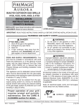
DELUXE CLASSIC SERIES
OUTDOOR GAS BARBECUE
42,000 BTU
For Natural and Propane Gas
INSTALLATION AND OPERATING
INSTRUCTIONS
INSTALLER: Leave these instructions with consumer.
CONSUMER: Retain for future reference.
IMPORTANT: READ THESE INSTRUCTIONS CAREFULLY BEFORE STARTING INSTALLATION OR USE.
FOR FIRE MAGIC BARBECUES: SERIES 61
Brick Opening: Depth 17-3/4", Width 24-3/4" Height 12", open front
SAFETY WARNINGS & CODES
FOR YOUR SAFETY
IF YOU SMELL GAS:
1.
2.
3.
4.
Shut off the gas to the appliance.
Extinguish any open flame.
Open lid.
If odor continues, immediately call
your gas supplier or fire department.
This appliance and its individual shutoff valves
must be disconnected from the gas supply piping
system when testing the system at pressures in
excess of ½ psig.
This appliance must be isolated from gas supply
piping system by closing its individual manual shutoff valves during any pressure testing of gas supply
system at pressures up to and including ½ psig.
FOR YOUR SAFETY
WARNING: Improper installation, adjustment,
1. Do not store or use gasoline or other
flammable vapors and liquids in the
vicinity of this or any other appliance.
2. A propane cylinder not connected for use
shall not be stored in the vicinity of this
or any other appliance.
alteration, service or maintenance can cause
injury or property damage. Refer to this manual.
For assistance or additional information consult
qualified, professional installer, service agency
or the gas supplier.
CODE AND SUPPLY REQUIREMENTS: This
barbecue must be installed in accordance
with local codes and ordinances, or in the
absence of local codes, with the latest National
Fuel Gas Code, ANSI Z223.1, or CAN/
CGA-B149.1, Natural Gas Installation Code
or CAN/CGA-B149.2, Propane Installation
Code..
Robert H. Peterson Co. • 14724 East Proctor Avenue, • City of Industry, CA 91746
REV 2 - 1406201000
1
L-C2-017
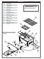
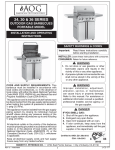
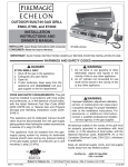
PARTS LIST
Item
Description
1.
Cooking grids (2)
2.
Flavor grid
3.
Main burner (2)
4.
Ignitor assy
#2 (medium) Phillips screwdriver
Two medium size adjustable wrenches or pliers
*3/8" wrench or 3/8" socket screwdriver
Pipe joint compound resistant to all gasses
5.
Liner assy
*Note: 3/8" socket if orifice change is required.
6.
Air shutter (2)
7.
Air shutter spring (2)
8.
Orifice (2)
9.
Burner manifold assy
10.
Valve manifold
11.
Face
12.
Spark generator
13.
Valve
14.
Control knob
15.
Spark generator knob
16.
Drip tray
TOOLS REQUIRED FOR INSTALLATION
1
2
3
Replacement parts can be ordered
from your local American Outdoor
Grill dealer.
5
4
6
11
7
10
8
15
13
12
16
REV 2 - 1406201000
9
14
2
L-C2-017
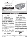
PLANNING FOR INSTALLATION
WHERE TO INSTALL YOUR BARBECUE
Fire Magic Barbecues are for outdoor use only.
WARNING: Built-in models must be installed
in masonry or other type of fireproof enclosure.
The unit is not insulated and therefore must be
installed with 18" of side and back clearance from
unprotected combustible materials such as wood,
plastic or stucco with wood framing.
With our insulating liner (Part #3100-50) you can
safely install your Fire Magic Barbecue in wood
cabinetry or other combustible enclosure.
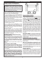
Figure 1 - Ventilation Diagram
For easy installation of your Fire Magic Barbecue
a masonry installation hanger (Part #3100-70 for
black finish & 3100-80 for Stainless Steel) is available.
It eliminates the requirement for any type of support
structure under the barbecue.
Propane Cylinder Enclosures
To prevent invisible combustible gas from accumulating
in your cylinder enclosure, you must provide
ventilation. This is accomplished by EITHER one side
of the gas cylinder enclosure left completely open
to the outside OR by providing four (4) ventilation
openings. Two openings are to be at the cylinder valve
level (Approx. 16” above the floor) and at opposite
walls of the enclosure. Two more openings must be
at the floor level at opposite sides of the enclosure.
The floor level openings must start at the floor
and shall extend no higher than 5” above the floor.
Each opening must have a minimum of 10 square
inches (64.5 cm2) of free area. To achieve the proper
ventilation, you may drill a series of holes, omit the
grout from masonry joints or replace a brick with a
hardware cloth screen. If the floor in the cabinet is
raised and the space beneath the cabinet is open to
the outside, the lower ventilation openings may be
in the floor.
Do not install this unit under unprotected flammable
surfaces. Do not install or use this appliance inside a
building, garage, or any other enclosed area including
recreational vehicles or boats.
This is a slide-in type unit designed to fit into
open-front enclosures. The front panel (face) of the
unit is removable for gas hookup, servicing and burner
adjustment. The face must therefore be removable
after you install the unit.
INSTALLER NOTE: This unit should be installed
so that it can be removed at a later date if factory
service is required. Any protrusion into the barbecue
enclosure may obstruct the frame and prevent the unit
from sliding into place (see "Gas Supply Plumbing
Requirements", on page 4).
FOR YOUR SAFETY, you must provide these
openings for drainage, replacement air and cross
ventilation of any storage area exposed to possible
leakage from gas connections, the barbecue or
propane cylinder.
INSURING PROPER COMBUSTION AIR AND
COOLING AIR FLOW
You must maintain proper air flow for your Fire Magic
Barbecue to perform as it was designed (Figure 1). If
airflow is blocked, overheating and poor combustion
will result. Make sure not to block the 1" front air
inlet along the bottom of the barbecue face or the air
vent openings along the outside-left and right edges
of the frame.
Note: The 1" front air space allows access to the
drip tray.
HOUSEHOLD PROPANE GAS SERVICE
Consult your gas supplier for ventilation and regulator
requirements when connecting to a HOUSEHOLD
propane supply.
Note: Only Fire Magic Barbecue models with the suffix
-PA- in the model number are approved by C.S.A.
for self contained propane cylinders. Supplemental
instructions are supplied with each self contained unit.
VENTILATION OF ENCLOSURES
When using propane gas, take EXTREME CAUTION
to ensure ample ventilation of gas vapor. Propane
vapor is invisible and heavier than air. A DANGEROUS
EXPLOSION could occur, resulting in SERIOUS
INJURY, if propane gas is allowed to accumulate and
is then ignited.
Installer and User Note: Keep electrical supply cords
away from all heated surfaces.
EXHAUST REMOVAL
If installed under a patio roof, the grill area should
be fully covered by a chimney and exhaust hood. An
exhaust fan with a rating of 1000 CFM or more may
be necessary to efficiently remove smoke and other
cooking by-products from the covered area. Installation
in fully-enclosed patio areas is not recommended.
Only one cylinder may be stored in an enclosure.
Extra or spare cylinders must be stored elsewhere.
Read and follow all warnings provided with
propane gas cylinders. Never locate a propane
cylinder below or adjacent to the barbecue unit
unless sufficient ventilation and shielding is
provided to prevent any heating of the cylinder,
regulator, and rubber hose.
REV 2 - 1406201000
3
L-C2-017
PLANNING FOR INSTALLATION (cont.)
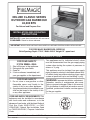
GAS SUPPLY PLUMBING REQUIREMENTS
Rigid 1/2" or 3/4" black steel pipe, or local code approved
pipe for temperatures up to 800°F (427°C), is required
to conduct the gas supply into the enclosure opening
for connection to the unit. Do not use a rubber hose
within the enclosure for the barbecue unit.
Apply only joint compounds that are resistant to all
gasses on all male pipe fittings. Make sure to tighten
every joint securely. Do not use pipe joint compound to
connect flare fittings.
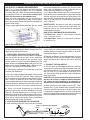
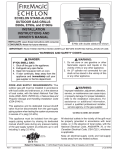
The gas supply pipe should enter from the rear wall of
the enclosure behind the barbecue unit, at least 2" from
either side, and between 2" and 8" above the floor as
illustrated by the shaded area in Figure 2.
If it is not possible to stub the gas line in from the back
of the enclosure, the connection may be made through
the floor at the rear of the enclosure. Install the gas line
stub at least 2" away from the side and back walls, but
within 6" of the back wall as illustrated by the shaded
area in Figure 2.
SAFETY NOTE: An external valve (with a removable
key) in the gas line is necessary for safety when your
barbecue is not in use. It also provides for convenient
maintenance and repair.
GAS SUPPLY AND MANIFOLD PRESSURES:
For Natural Gas - normal 7" water column, minimum
3 1/2", maximum 10-1/2".
For Propane Gas - normal 11" water column, minimum
8", maximum 13".
Figure 2 - Gas Stub Diagram
INSTALLATION
Perform the following checks before installing your Fire
Magic Deluxe Classic Barbecue:
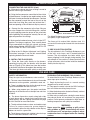
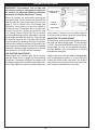
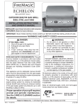
spring and the air shutter over the orifice holder fitting,
between the burner and the pipe manifold, in the order
and position shown in Figure 3.
1. CHECK FUEL ORIFICES FOR PROPER SIZE
a. Your Fire Magic Deluxe Classic Barbecue is equipped
with fuel orifices for natural gas, unless otherwise
indicated. To use with propane gas, you must install
smaller orifices to avoid hazardous overheating. The
proper orifice size for Natural Gas is #47 (drill size). The
proper orifice size for Propane Gas is #55 (drill size).
The size is stamped on the face of the orifice.
b. Replace the burners in the holding groove, ensuring
that the brass orifice and orifice holder fittings project
deeply into the burners. Replace the burner retaining
clips.
3. CONNECT THE GAS SUPPLY
a. You will need an CSA approved stainless steel flex
connector to bring the gas supply from the gas line stub
to the valve manifold. A 1/2" x 36" or 48" flex connector
with 1/2" flare to 1/2" pipe adapter on one end, and a
1/2" flare female fitting on the other end is suitable for
most installations.
CAUTION: Use only stainless steel flex connectors
that are C.S.A. listed. A rubber or plastic connector
will rupture or leak, resulting in an explosion or
serious injury if used inside the barbecue enclosure.
b. Remove the cooking grills, smoke oven and flavor
grid from your barbecue.
c. If the gas supply has been connected, make sure the
burner valve is in the “OFF” position. Then carefully pull
the valve knob and rotary ignition knob from their stems.
Use a Phillips screwdriver to turn the face fastener
screws counterclockwise to release the face and remove
it from the barbecue. Make sure to retain the screws and
finish washers until you are ready to reattach the face.
b. Make sure that your gas supply is turned 'OFF'. Then
connect the 1/2" pipe adapter fitting supplied with the
stainless steel flex connector to the gas supply stub.
Use pipe joint compound that is resistant to all gasses
on the male pipe fitting and tighten securely. Do not use
pipe joint compound to connect the flare fittings.
d. Using a flat blade screwdriver, pry the burner
retaining clip from rear wall of the barbecue frame (see
Figure 4). Remove the burner by; A) Pulling it to the
front of the barbecue, B) Lift the far end out of the notch,
C) Pull the burner away from the manifold, taking care
not to lose air shutter and spring, which may become
detached when the burner is removed.
2. POSITION THE BURNERS FOR OPERATION
a. After checking orifice drill size install the air shutter
Figure 3 - Burner Orifice Diagram
BURNER
BURNER NECK
SPRING
BURNER
MANIFOLD WITH
ORIFICE HOLDER
BURNER CLIP
AIR SHUTTER
REV 2 - 1406201000
4
ORIFICE
L-C2-017
INSTALLATION (cont.)
CONNECTING THE GAS SUPPLY (Cont.)
c. Slide your barbecue into place, making sure not to
pinch or kink the gas connector.
FLAVOR GRID
LEGS
d. Bring the flex connector around the left-hand side
of the barbecue. Use the locator angle brackets on the
left lower-frame to position the flex connector. Continue
the flex connector around the front of the unit to the
valve inlet flare fitting. Be careful not to block the 1"
front vent opening as this will obstruct drip tray removal.
BURNER
e. Connect the flex connector to the flare fitting on
the valve. Support the valve inlet fitting with a wrench
to avoid applying excessive torque to the valve body
while tightening this connection securely. Do not use
pipe compound on flare fittings.
Figure 4 - Flavor Grid Diagram
Fire Magic Barbecue very responsive to the changes
you specify in grill temperature.
f. Make sure the barbecue burner valve is in the 'OFF'
position. Turn the gas supply on. Then carefully check
all gas connections for leaks with a brush and soapy
water before lighting. NEVER USE A MATCH OR
OPEN FLAME TO TEST FOR LEAKS.
The flavor grid is made of 304 stainless steel. It is
rust resistant and may be cleaned with standard oven
cleaners.
5. DRIP COLLECTION SYSTEM
The drip collector in this Fire Magic Barbecue is part
of the unit’s main frame, and is located below the
burners. The drip collector has holes which allow
excess drippings to fall through during cooking. The
drip collector is also useful as it allows you to brush or
scrape off excess dried residue inside the barbecue
directly into the drip tray.
g. Refer to the 'Air Shutter Adjustment' and 'Lighting
Instructions' on pages 7 and 8 of this manual before
replacing barbecue face and knobs.
4. INSTALL THE FLAVOR GRID
a. Place the flavor grids directly on the burners,
centering the grids over the burners with the open
side up (Figure 4).This allows heat from the burners
to be evenly distributed throughout the cooking area.
The flavor grid heats and cools quickly, making your
USE AND CARE
SAFETY INFORMATION
Every time you use your barbecue, make sure that:
PREPARING THE BARBECUE FOR COOKING
To extend the life of your Fire Magic Barbecue, follow
these steps prior to cooking:
1. The area around the barbecue is clear of flammable
substances such as gasoline, yard debris, wood, etc. 1. Begin by heating the unit at a normal cooking
temperature for several minutes.
2. There is no blockage of the air flow through the vent
2. Then open the control valve to the 'HIGH' setting to
space located below the face of the unit.
burn off residue remaining from prior use.
3. When using propane gas, the special ventilation
openings in the enclosure must be kept free and clear 3. When the barbecue has heated sufficiently, set heat
to the desired cooking level.
of debris.
4. When using a smoke oven, closing the cover during
the preheat period will accelerate the preparation
process. Do not operate unattended at high flame as
cooking temperatures will quickly be exceeded.
4. The burner flames burn evenly along both sides
of each burner with a steady flame (mostly blue with
yellow tipping). See the 'Lighting Instructions' on page
8 of this manual for more information.
5. The drip collector holes are clear and unobstructed.
WARNING:
Failure to remove excessive grease deposits Never cover the entire cooking or grill surface
accumulated in either the drip collector or the drip tray
with griddles or pans. Overheating will occur
below can result in a grease fire.
and burners will not perform properly when
6. The in-line gas valve or tank (cylinder) valve is always combustion heat is trapped below the cooking
shut-off when the barbecue is not in use.
surface.
REV 2 - 1406201000
5
L-C2-017
USE AND CARE (cont.)
FLAVOR FROM WOOD CHIPS OR CHARCOAL
Convenient Fire Magic Gourmet Grilling Chips are sold
in several different popular wood types. These chips are
pre-moistened and sealed in cans which can be opened,
by lifting the tabbed lid, before placing
the entire can on the flavor grid to add natural wood
smoke flavor to the food you grill. There is no mess to
clean up. Just discard the can of ashes after there is no
longer any wood smoke aroma.
Oven cleaner may be used, according to manufacturer’s
instructions, to remove cooked-on food deposits. Special
cleaning agents and polishing pads recommended for
stainless steel are available at your local barbecue dealer,
hardware store or supermarket.
CAUTION: Never use ordinary steel wool or steel
brushes on stainless steel. Tiny particles left behind may
rust and stain the finish. Abrasive pads recommended
for restoring the grain in stainless steel will, over a period
of time, scratch or dull the surface of glass or porcelaincoated products.
You may also add wood chips, wood chunks or the
natural wood charcoal of your choice to the flavor grid.
We recommend placing wood outside the direct cooking
zone or wrapping it in perforated aluminum foil. Soaking
wood before use will slow burning and increase smoke
flavor. Wood and charcoal ash will remain in the flavor grid
after use. The grid can be easily removed and cleaned
when the unit has fully cooled.
CLEANING YOUR BARBECUE
The frame liner and many front panels (faces) of Fire
Magic Barbecues are porcelainized to provide many
years of trouble-free service. These surfaces may be
cleaned with Fire Magic Foaming Barbecue and Grill
Cleaner or with oven cleaner, following manufacturer’s
instructions.
CARE OF STAINLESS STEEL COMPONENTS
If your barbecue has a stainless steel oven or front
panel, the following care instructions will keep your
unit looking and working like new. Stainless steel
components are constructed of the finest prime grade
type 304 stainless steel. Meticulous attention has been
given to maintaining the attractive finish throughout the
manufacturing process. Like the stainless steel used in
commercial kitchens, your barbecue requires regular
cleaning and occasional buffing to maintain its bright,
clean appearance.
CARE OF COOKING GRIDS
If your Fire Magic Barbecue has porcelain-coated
or stainless steel cooking grids, the following care
instructions will keep them looking and performing like
new.
Stainless steel rod grids, high temperature porcelainized
rod or our special high temperature porcelainized matte
(satin) finished cast iron cooking grids, will give you years
of corrosion-free service.
Deposits of dirt and grease can be removed easily with
Fire Magic Foaming Barbecue and Grill Cleaner.
Deposits should be removed before they are allowed to
bake onto the finish.To remove more stubborn deposits,
use a scouring pad recommended for stainless steel.
Be sure to always rub in the direction of the polishing
lines (Figure 5).
We recommend that you spray a light coat of vegetable
oil on your cooking grids and then brush them lightly
with a cleaning pad or a brass wire grill brush before
and after use to insure maximum life and insure their
cooking readiness.
CAUTION: Never use acid chemicals to clean porcelain
surfaces.
CARE OF UNCOATED CAST IRON COOKING GRIDS
All uncoated cast iron will rust if not properly seasoned.
Please read and follow the seasoning instructions below
to ensure long life and proper performance.
The special qualities of properly seasoned cast iron
cooking grids (quick, even heating, sustained heat
retention, nonstick cooking and excellent searing
capabilities) make them the preferred choice of master
chefs. Only an uncoated cast iron cooking surface that’s
been properly treated and maintained can offer these
qualities.
in
Wipe with gra
Your Fire Magic Cast-Iron Cooking Grids are heavier with
the bars closer spaced than most other grids, retaining
maximum temperatures even when suddenly covered
with cold meat. Because of this, they sear in the natural
juices so you can enjoy the full flavor of your favorite cuts.
Figure 5 - Always rub with the grain
REV 2 - 1406201000
6
L-C2-017
USE AND CARE (cont.)
temperatures for extended periods, may dry out the
cast iron and make it more susceptible to rusting. If
grids do become overheated and dry out, repeat the
initial seasoning procedure. Rust can be prevented
by keeping your grids properly seasoned. Wrap the
grids in newspaper or paper towels and store them
in a dry place if you are not planning to use them for
several weeks.
SEASONING YOUR CAST IRON GRIDS
Initial Seasoning: Wash the cooking grids
thoroughly with a mild detergent and scrub brush,
rinse and dry. Saturate the cast iron surfaces with a
high-quality vegetable cooking oil. The grids can be
immersed, or the oil thoroughly worked into the cast
iron by brushing and/or swabbing. Allow the oil to
run off or drain, then bake the grids in the barbecue
oven at a low (275° to 325°) temperature for two to
three hours. Re-oil and wipe off the excess with a
clean rag or paper towel. Your cast iron grids are
now ready for use.
USE AND MAINTENANCE
For best cooking performance, the wide side of the
cooking grid bars should be face up. After each use,
brush off any residue, preferably while the grids are
still warm. A brass wire brush is ideal. Apply vegetable
oil with a clean cloth or spray can. Brush in and wipe
clean with a rag or clean paper towel. Your cast iron
grids are now ready for their next nonstick cooking
performance.
BURNER MAINTENANCE
Fire Magic Burners are constructed of heavy-duty,
high-quality porcelain coated cast iron, cast stainless
steel or cast brass and will withstand many years of
outdoor use, if the following ordinary precautions
are taken:
Once or twice a year inspect the burners and
determine if scale is building up excessively. Burners
can be removed and scraped to remove debris or
scale from the ports. Spray burners with vegetable
oil occasionally to inhibit oxidation. Replace burners
immediately if they show any signs of weak or thin
walls. Refer to page 4 for reinstalling burners.
Occasionally turn grids over and brush off accumulated
residue that could ignite during high temperature
cooking. Cooking food particles off the grids at high
CAUTION:
Never spray water on a hot gas unit as this may
damage porcelain or cast iron components.
The grill serial identification number is located on the underside of the drip tray handle. It
is recommended that the drip tray first be removed and cleaned / emptied of its contents,
then turned over to view.
REV 2 - 1406201000
7
L-C2-017
BURNER ADJUSTMENT
IMPORTANT: This barbecue will not light and
will not heat evenly or cook properly unless the
air shutters are adjusted following installation
(reference "Air Shutter Adjustment", below).
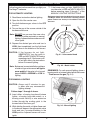
PARTIALLY OPEN
FIGURE 6A
Burner air shutters are accessed by removing the
front panel (face). The air shutters are located at the
end of the burners on the right side of the unit (see
page 2). The air shutter has a small dimple (see
Figure 6A), which allows it to lock into notches in
the burner face. This prevents the air shutter from
moving. Close the air shutters by turning the tabs
to a vertical position (Figure 6B). The air shutters
on Deluxe Barbecues can be adjusted by using the
match holder (provided with each unit - Figure 8, page
8). Place the ring over the air shutter tab and push
or pull to adjust the opening. Close the air shutters
with the tabs pointing up and down (Figure 6B). Light
your barbecue in accordance with the manual lighting
instructions found on page 8 and burn for 5 minutes
with the burners on 'HIGH' and the oven open.
CLOSED
FIGURE 6B
Figure 6A & 6B - Air Shutter Adjustment Diagram
on the flames. If flames are a lazy yellow, open the
air shutters until the flame is blue with yellow tipping.
ADJUSTING THE FLAME HEIGHT
The large knob on the face of the barbecue controls
the valve and adjusts flame height. The first position
is 'HIGH', the second 'MEDIUM' and the final 'LOW'.
flame height can also be set anywhere between
the High, Medium, and Low settings for all cooking
requirements and tastes.
AIR SHUTTER ADJUSTMENT
After burning for 5 minutes, open the air shutters
until the flames lift off, or appear not to be touching
the burners. Then begin closing the air shutters until
the flames appear to burn while touching the burner
ports (Figure 6B). You may then see short yellow tips
REV 2 - 1406201000
Height of the flame with the valve in low position
may be regulated by means of a small adjusting
screw in the center of the valve stem. This screw is
accessible by removing the plastic valve knob which
pulls straight off the end of the valve stem.
8
L-C2-017
LIGHTING INSTRUCTIONS
Follow these instructions each time you light your
Fire Magic® barbecue.
7. If the burner does not light, IMMEDIATELY
turn the valve to OFF and WAIT 5 MINUTES
before repeating steps 5 through 7 of the
MANUAL LIGHTING INSTRUCTIONS.
FOR AUTOMATIC LIGHTING
Replacement parts may be obtained from your nearest
Fire Magic® dealer. For assistance in locating a dealer,
please contact our factory at the address listed on
the cover.
1. Read these instructions before lighting.
2. Open the lid of the smoke oven.
3. Turn both barbecue gas valves to the OFF
position.
OFF MARKER
TO
Note: DO NOT turn on more than one valve
at a time for either automatic or manual
lighting. Adjacent barbecue burners will
cross-ignite.
OFF
PU
TU SH
RN TO
FF
O
TU
R
N
N
R
TU
O
N
TO
4. Turn on the gas at the source outside of the
barbecue enclosure.
HI
LIGHT
5. Depress the desired gas valve and turn to
HIGH, then immediately turn the light knob
several times in the direction of the arrows.
HIGH TO
LIGHT
ME
D
CAUTION: If the bur ners do not light,
IMMEDIATELY turn the valve to
OFF and WAIT 5 MINUTES before
repeating step 5. If the burners still
do not light, refer to the instructions
below for manual lighting.
Fig. 9-1 - Valve control knob
Fig. 9-2 - Match holder
Note: Barbecues in some installations achieve
a better air/gas mixture and will ignite
more quickly if the valve is first turned
beyond HIGH to MEDIUM or LOW for
lighting.
REMEMBER: For safe manual lighting, place a
burning match or butane lighter beside the burner
- Then turn on the gas (Fig. 9-3).
FOR MANUAL LIGHTING
CAUTION: Always wait 5 minutes for gas
to clear after any unsuccessful
lighting attempt.
Follow steps 1 through 4 above.
5. Insert either a burning long-barrel butane
lighter, a burning long-stem match, or a
burning match held by a wire extension
holder through the cooking grids to the
burners below the flavor grid.
Fig. 9-3 - Manual lighting
6. While holding the match or lighter flame next
to the burner, depress the appropriate valve
knob and turn it counter-clockwise to the
HIGH position. Adjacent burners will crossignite.
9
WARRANTY
PETERSON FIRE MAGIC GRILLS AND ACCESSORIES
LIMITED WARRANTY
Robert H. Peterson Co. ("RHP") warrants your Fire Magic® grill to be free from defects in material and workmanship.
Fire Magic® cast stainless-steel burners, stainless-steel rod cooking grids, and stainless-steel housings are warranted for as long as you own
your Fire Magic® grill -- LIFETIME. (Except as noted below.)
Fire Magic Choice stainless steel tubular burners are warranted for TWENTY (20) YEARS.
Fire Magic® cast brass burners, brass valves, inner liners, manifold assemblies, and backburner assemblies (except ignition parts) are
warranted for FIFTEEN (15) YEARS.
Fire Magic® Electric Grills, including stainless steel grid, and housings are warranted for TEN (10) YEARS.
Fire Magic® Infra-red burners, flavor grids, Charcoal stainless steel grills, and Smokers are warranted for FIVE (5) YEARS; except for the
charcoal pan, charcoal grid, wood pellet screen, thermometer, and ash tray; which are warranted for ONE (1) YEAR.
Fire Magic® sideburners and all other Fire Magic® grill components (except ignition and electronic parts) are warranted for THREE (3)
YEARS.
Fire Magic® ignition systems (excluding batteries), electronic components (including lights and thermometers), and grill accessories are
warranted for ONE (1) YEAR.
A COPY OF YOUR SALES SLIP FOR PROOF OF PURCHASE IS REQUIRED
This warranty applies to the original purchaser for products which are installed in the United States or Canada and which are operated and maintained
as intended for single family residential usage. This warranty is valid only with proof of purchase, shall commence on the date of purchase, and shall
terminate (both as to original and any replacement products) on the anniversary date of the original purchase of the product stated on the above schedules.
This warranty covers defects in material and workmanship. This warranty does not cover parts which become defective as a result of negligence, misuse,
use not in compliance with the Owner’s Manual/Installation Instructions, accidental damage, improper handling, improper storage, improper installation,
lack of required routine maintenance (as specified in the Owner’s Manual/Installation Instructions), electrical damage, local gas impurities or failure to
protect against combustibles. Product must be installed (and gas must be connected) as specified in the Owner’s Manual/Installation Instructions by
a qualified professional installer. Modifications to products which are not specifically authorized will void this warranty. Accessories, parts, valves,
remotes, etc. when used must be Peterson products or this warranty is void. Warrantied items will be repaired or replaced at Peterson’s sole discretion.
This warranty does not apply to rust, corrosion, oxidation, or discoloration unless the affected part becomes inoperable.
This warranty does not cover labor or labor related charges, except as provided by separate specific written programs from the Peterson Co. All repair
work must be performed by a qualified professional service person and requires prior approval of Peterson.
Peterson may require the defective product or part to be returned to the factory to determine the cause of failure. Peterson will pay freight charges if
the product or part is determined to be defective. This warranty does not cover breakage in shipment from our (Independent) distributor to its customer
if the damage is determined to have occurred during that shipment.
This warranty specifically excludes liability for indirect, incidental, or consequential damages. Some states and provinces do not allow the exclusion
or limitation of incidental or consequential damages, so the above exclusion may not apply to you. This warranty gives you specified legal rights, and
you may have other rights that vary from state to state or province.
For additional information regarding this warranty, or to place a warranty claim, contact the R. H. Peterson dealer where the product was purchased.
TO REGISTER YOUR PRODUCT ONLINE GO TO: WWW.RHPETERSON.COM,
AND CLICK ON PRODUCT REGISTRATION. THANK YOU FOR YOUR PURCHASE.
Quality Check
Burner Orifices Nat.
Date:_________________
L.P.
Leak Test: ___________ Model#:
___________________
Main:
____ ____
Burn Test: ___________ Serial#:
___________________
Other:
____ ____
Gas Type:
Nat. / L.P.
Air Shutter: ___________________
Inspector:
___________________
Robert H. Peterson Co. • 14724 East Proctor Avenue • City of Industry, CA 91746
10