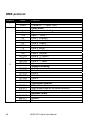
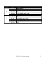
1
RUSH DC 1 Aqua User Manual Professional Entertainment Technology © 2013-2014 Martin Professional ApS. Information subject to change without notice. Martin Professional and all affiliated companies disclaim liability for any injury, damage, direct or indirect loss, consequential or economic loss or any other loss occasioned by the use of, inability to use or reliance on the information contained in this manual. The Martin logo, the RUSH by Martin logo, the RUSH by Martin name, the Martin name and all other trademarks in this document pertaining to services or products by Martin Professional or its affiliates and subsidiaries are trademarks owned or licensed by Martin Professional or its affiliates or subsidiaries. Martin Professional • Olof Palmes Allé 18 • 8200 Aarhus N •Denmark • www.martin.com Manual: Revision C Table of contents Safety information ............................................................................................. 5 Introduction ..................................................................................................... 10 Before using the product ............................................................................. 10 Physical installation......................................................................................... 11 Fastening the fixture to a flat surface .......................................................... 11 Mounting the fixture on a truss .................................................................... 11 Securing with a safety cable........................................................................ 12 AC power ........................................................................................................ 13 Linking fixtures to power in a chain ............................................................. 14 Fixture overview .............................................................................................. 15 Control data link .............................................................................................. 17 Tips for reliable data transmission .............................................................. 17 Connecting the DMX data link ..................................................................... 18 Fixture setup ................................................................................................... 18 Using the control menus.............................................................................. 18 DMX addressing .......................................................................................... 18 Standalone operation .................................................................................. 19 Backlight ...................................................................................................... 20 Manual Mode / manual standalone control ................................................. 20 Auto test ...................................................................................................... 21 Temperature ................................................................................................ 21 Fixture operating hours readout .................................................................. 21 Software version .......................................................................................... 21 Reset ........................................................................................................... 21 Effects ............................................................................................................. 22 Water effect ................................................................................................. 22 Color control ................................................................................................ 22 Electronic dimming ...................................................................................... 22 Focus ........................................................................................................... 23 Maintenance ................................................................................................... 24 Cleaning ...................................................................................................... 24 Replacing the primary fuse.......................................................................... 25 DMX protocol .................................................................................................. 26 Control menus ................................................................................................. 28 Troubleshooting .............................................................................................. 30 Specifications .................................................................................................. 31 Safety information WARNING! Read the safety precautions in this manual before installing, operating or servicing this product. The following symbols are used to identify important safety information on the product and in this manual: Warning! Warning! Safety hazard. Powerful light Risk of severe emission. Risk injury or of eye injury. death. Warning! Warning! Warning! See user manual for important safety information. Hazardous voltage. Risk of lethal or severe electric shock. Hot surfaces and fire hazard. Warning! Risk Group 1 product according to EN 62471. Do not stare directly into the beam. Do not view the light output with optical instruments or any device that may concentrate the beam. This lighting fixture is for professional use only – it is not for household use. The fixture must be installed by a qualified technician. The safety of the installation is the responsibility of the installer. The fixture presents risks of severe injury or death due to fire hazards, electric shock and falls. It produces a powerful, concentrated beam of light that can create a fire hazard or a risk of eye injury if the safety precautions below are not followed. If you have any questions about how to install, operate or service the fixture safely, please contact your Martin™ distributor (see www.martin.com/distributors for details) or call the Martin™ 24-hour service hotline on +45 8740 0000, or in the USA on 1888-tech-180. RUSH DC1 Aqua User Manual 5 Respect all locally applicable laws, codes and regulations when installing, operating or servicing the fixture. There are no user-serviceable parts inside the fixture. Do not open it. Refer any service or repair operation not described in this manual to an authorized Martin™ service technician. Do not try to carry out any such operation yourself, as doing so may present a health or safety risk. It may also cause damage or malfunction and it may void your product warranty. Install, operate and service RUSH by Martin™ products only as directed in their user manuals, or you may create a safety hazard or cause damage that is not covered by product warranties. Follow the safety precautions listed below and observe all warnings in this manual and printed on the product. Keep this user manual for future use. For the latest user documentation and other information for this and all Martin™ products, please visit the Martin website at http://www.martin.com Protection from electric shock Do not expose the fixture to rain or moisture. Disconnect the fixture from AC power before carrying out any installation or maintenance work and when the fixture is not in use. Ensure that the fixture is electrically connected to ground (earth). Use only a source of AC power that complies with local building and electrical codes and has both overload and ground-fault (earth-fault) protection. Socket outlets or external power switches used to supply the fixture with power must be located near the fixture and easily accessible so that the fixture can easily be disconnected from power. Replace defective fuses with ones of the specified type and rating only. Isolate the fixture from power immediately if the power plug or any seal, cover, cable, or other component is damaged, 6 RUSH DC1 Aqua User Manual defective, deformed, wet or showing signs of overheating. Do not reapply power until repairs have been completed Before using the fixture, check that all power distribution equipment and cables are in perfect condition and rated for the electrical requirements of all connected devices. Use only Neutrik PowerCon cable connectors to connect to the fixture’s power sockets. Do not connect devices to power in a chain that will exceed the electrical ratings of any cable or connector used in the chain. The supplied power input cable is rated 6 A and can safely supply only one fixture with mains power. Do not connect any device to the fixture’s MAINS OUT connector when using this cable. If you replace this cable and also use the replacement cable to supply only one fixture with mains power, the replacement cable must also be rated 6 A minimum, have three conductors 18 AWG or 0.75 mm² minimum conductor size, have an outer cable diameter of 6 - 15 mm (0.2 - 0.6 in.) and be temperature-rated to suit the application. In the USA and Canada the cable must be UL listed, type SJT or equivalent. In the EU the cable must be type H05VV-F or equivalent. To connect fixtures to mains power in a chain, you must first obtain 14 AWG or 1.5 mm2 power input and throughput cables that are 16 A rated and temperature-rated to suit the application. In the USA and Canada the cables must be UL-listed, type SJT or equivalent. In the EU the cables must be type H05VV-F or equivalent. Suitable cables with Neutrik PowerCon connectors are available from Martin™ (see ‘Accessories’ on page 33). If you use these cables, you can connect fixtures to power in a linked chain, MAINS OUT throughput socket to MAINS IN input socket, but do not link more than: • Twelve (12) RUSH DC1 Aqua fixtures in total at 100-120 V, or • Twenty-eight (28) RUSH DC1 Aqua fixtures in total at 200-240 V. The voltage and frequency at the MAINS OUT socket are the same as the voltage and frequency applied to the MAINS IN socket. Only connect devices to the MAINS OUT socket that accept this voltage and frequency. RUSH DC1 Aqua User Manual 7 Protection from burns and fire Do not use the fixture to illuminate surfaces within 200 mm (7.9 ins.) of the fixture. Do not operate the fixture if the ambient temperature (Ta) exceeds 40° C (104° F). The surface of the product casing can reach up to 43° C (110° F) during operation. Avoid contact by persons and materials. Allow the fixture to cool for at least 10 minutes before handling. Keep flammable materials well away from the fixture. Keep all combustible materials (e.g. fabric, wood, paper) at least 100 mm (4 in.) away from the fixture. Ensure that there is free and unobstructed airflow around the fixture. Provide a minimum clearance of 100 mm (4 in.) around fans and air vents. Do not attempt to bypass thermostatic switches or fuses. Do not stick filters, masks or other materials onto any optical component. Protection from eye injury Do not stare directly into the light output. Ensure that persons are not looking directly into the LEDs when the product lights up suddenly. This can happen when power is applied, when the product receives a DMX signal, or when certain control menu items are selected. Do not look at the light output with magnifiers, telescopes, binoculars or similar optical instruments that may concentrate the light output. To minimize the risk of eye irritation or injury, disconnect the fixture from power at all times when the fixture is not in use, and provide well-lit conditions to reduce the pupil diameter of anyone working on or near the fixture. Protection from injury Fasten the fixture securely to a fixed surface or structure when in use. The fixture is not portable when installed. 8 RUSH DC1 Aqua User Manual Ensure that any supporting structure and/or hardware used can hold at least 10 times the weight of all the devices they support. If suspending from a rigging structure, fasten the fixture to a rigging clamp. Do not use safety cables as the primary means of support. If the fixture is installed in a location where it may cause injury or damage if it falls, install as directed in this manual a secondary attachment such as a safety cable that will hold the fixture if a primary attachment fails. The secondary attachment must be approved by an official body such as TÜV as a safety attachment for the weight that it secures, must comply with EN 60598-2-17 Section 17.6.6 and must be capable of bearing a static suspended load that is ten times the weight of the fixture and all installed accessories. Check that all external covers and rigging hardware are securely fastened. Do not operate the fixture with missing or damaged covers, shields or any optical component. If shields, lenses or ultraviolet screens have become visibly damaged to such an extent that their effectiveness is impaired, for example by cracks or deep scratches, the fixture must be returned to an authorized Martin™ service agent for replacement. Block access below the work area and work from a stable platform whenever installing, servicing or moving the fixture. In the event of an operating problem, stop using the fixture immediately and disconnect it from power. Do not attempt to use a fixture that is obviously damaged. Do not modify the fixture in any way not described in this manual or install other than genuine RUSH by Martin™ parts. RUSH DC1 Aqua User Manual 9 Introduction The RUSH DC 1 Aqua™ is a dynamic effect lamp that projects moving water effects. It has a 75 W LED engine with long-life white LEDs. Besides fully adjustable water effect projections, the DC 1 Aqua features a color wheel with five color flags and smooth 0-100% continuous electronic dimming. The fixture is rugged, lightweight and compact. The DC 1 Aqua can be controlled using any DMX-compliant controller or it can run in standalone mode with a choice of three shows. Fixtures in standalone mode can be linked and their shows synchronized in master/slave operation. The fixture is supplied with this user manual, a 1.5 m (5 ft.) power cable (local power plug not included) and a folding bracket that can also be used for rigging clamp attachment. Before using the product 1. Read ‘Safety information’ on page 5 before installing, operating or servicing the fixture. 2. Unpack and ensure that there is no transportation damage before using the fixture. Do not attempt to operate a damaged fixture. 3. If the fixture is not going to be hard-wired to a mains supply, install as directed in this manual a local power plug (not supplied) on the supplied power cable. 4. Before operating, ensure that the voltage and frequency of the power supply match the power requirements of the fixture. 5. Check the RUSH support pages on the Martin Professional website at www.martin.com for the most recent user documentation and technical information about the fixture. RUSH by Martin™ user manual revisions are identified by the revision letter at the bottom of the inside cover. Note that when the fixture is powered on for the first time, it may smoke slightly as it warms up, but this will only last a few minutes and is no cause for concern. 10 RUSH DC1 Aqua User Manual Physical installation Read ‘Safety information’ on page 5 before installing the fixture. The fixture is designed for indoor use only and must be used in a dry location with adequate ventilation. Ensure that none of the fixture’s ventilation slots are blocked. Fasten the fixture to a secure structure or surface. Do not stand it on a surface or leave it where it can be moved or fall over. If you install the fixture in a location where it may cause injury or damage if it falls, secure it as directed in this user manual using a securely anchored safety cable that will hold the fixture if the primary fastening method fails. Martin™ can supply suitable safety cables and rigging clamps for use with the fixture (see ‘Accessories’ on page 33). Fastening the fixture to a flat surface The fixture can be fastened to a hard, fixed, flat surface that is oriented at any angle. Ensure that the surface and all fasteners used can support at least 10 times the weight of all fixtures and equipment to be installed on it. Fasten the fixture securely. Do not stand it on a surface or leave it where it can be moved or fall over. If you install the fixture in a location where it may cause injury or damage if it falls, secure it as directed below with a securely anchored safety cable that will hold the fixture if the primary fastening method fails. Mounting the fixture on a truss The fixture can be clamped to a truss or similar rigging structure in any orientation. When installing the fixture hanging vertically down, you can use an open-type clamp such as a G-clamp. When installing in any other orientation, you must use a half-coupler clamp (see illustration on right) that completely encircles the truss chord. To clamp the fixture to a truss: 1. Check that the rigging structure can support at least 10 times the weight of all fixtures and equipment to be installed on it. 2. Block access under the work area. RUSH DC1 Aqua User Manual 11 3. Fold the legs of the mounting bracket together and bolt a rigging clamp securely to the mounting bracket. The bolt used must be M12, grade 8.8 steel minimum. It must pass through both mounting bracket legs and be fastened with a self-locking nut. 4. Working from a stable platform, hang the fixture with its clamp on the truss and fasten the clamp securely. 5. Secure the fixture with a safety cable as directed below. Securing with a safety cable Secure the fixture with a safety cable (or other secondary attachment) that is approved for the weight of the fixture so that the safety cable will hold the fixture if a primary attachment fails. Loop the safety cable through the eyebolt in the back of the fixture (see 3 in illustration on page 15) and around a secure anchoring point. Do not loop the safety cable around the fixture’s mounting bracket only, as this will leave the fixture unsecured if it separates from the bracket. 12 RUSH DC1 Aqua User Manual AC power Read ‘Safety information’ on page 5 before connecting the fixture to AC mains power. Warning! The mains power input cable supplied with the fixture is rated 6 A and can supply only one fixture with mains power. Do not connect any device to the fixture’s MAINS OUT power throughput socket when using this input cable. If you want to connect other fixtures to the MAINS OUT socket, see ‘Linking fixtures to power in a chain’ on page 14. For protection from electric shock, the fixture must be grounded (earthed). The power distribution circuit must be equipped with a fuse or circuit breaker and ground-fault (earth-fault) protection. Socket outlets or external power switches used to supply the fixture with power must be located near the fixture and easily accessible so that the fixture can easily be disconnected from power. Do not insert or remove live power connectors to apply or cut power, as this may cause arcing at the terminals that will damage the connectors. Do not use an external dimming system to supply power to the fixture, as this may cause damage to the fixture that is not covered by the product warranty. The fixture can be hard-wired to a building electrical installation if you want to install it permanently, or a power plug (not supplied) that is suitable for the local power outlets can be installed on the power cable. If you install a power plug on the power cable, install a grounding type (earthed) plug with integral cable grip that is rated minimum 250 V, 6 A. Follow the plug manufacturer’s instructions and connect the wires in the power cable as shown in this table: Live or L Neutral or N US system Black White Green EU system Brown Blue Yellow/green Earth, Ground or The fixture has an auto-ranging power supply that accepts AC mains power at 100V~240V, 50/60Hz. Do not apply AC mains power at any other voltage or frequency to the fixture. RUSH DC1 Aqua User Manual 13 Linking fixtures to power in a chain If you obtain a 14 AWG / 1.5 mm2 power input cable and 14 AWG / 1.5 mm2 throughput cables from Martin™ (see ‘Accessories’ on page 33), you can relay mains power from one fixture to another by connecting fixtures to power in a linked daisy-chain, MAINS OUT throughput socket to MAINS IN input socket. Using 14 AWG or 1.5 mm2 cables from Martin™, you can link: • Maximum twelve (12) RUSH DC1 Aqua fixtures in total at 100-120 V, or • Maximum twenty-eight (28) RUSH DC1 Aqua fixtures in total at 200-240 V. If you install a power plug on the 14 AWG / 1.5 mm2 power input cable available from Martin™, install a grounding type (earthed) plug with integral cable grip that is rated minimum 16 A, 250 V. 14 RUSH DC1 Aqua User Manual Fixture overview 1 - Display 2 - Status LEDs The LEDs on the control panel give the following indications: DMX MASTER SLAVE On On On DMX input present Master mode Slave mode 3 - Buttons The four buttons on the control panel have the following functions: • • DOWN Activate menus, or Return to the previous level of the menu structure, or • Hold to exit the menus (this occurs automatically after a period where there has been no user input). Go down a menu branch UP Go up a menu branch ENTER Confirm the selected function MENU RUSH DC1 Aqua User Manual 15 4 - DMX input/output sockets A 5-pin male XLR socket accepts input from a DMX512 data link. A 5-pin female XLR output (thru) socket allows the DMX link to be daisy-chained to the next fixture. 5 - Mains power input A blue Neutrik PowerCon socket is provided to connect the fixture to AC mains power. 6 - Mains power throughput The white Neutrik PowerCon socket can be used to supply power to other fixtures only if you respect the safety precautions given in this manual (see ‘Safety information’ on page 5). 7 - Fuse The fixture’s T 3.15A fuse is located in a fuseholder next to the display. 8 - Safety cable attachment point Eyebolt for securing the fixture with a secondary attachment such as a safety cable. 16 RUSH DC1 Aqua User Manual Control data link A DMX 512 data link is required in order to control the fixture via DMX or to use the master/slave functionality. The fixture has 5-pin XLR connectors for DMX data input and output. The number of daisy-chained fixtures is limited by the number of DMX channels required by the fixtures in relation to the maximum 512 channels available in one DMX universe. Note that if independent control of a fixture is required, it must have its own DMX channels. Fixtures that are required to behave identically can share the same DMX address and channels. To add more fixtures or groups of fixtures when the above limit is reached, add a DMX universe and another daisy-chained link. Tips for reliable data transmission Use shielded twisted-pair cable designed for RS-485 devices: standard microphone cable cannot transmit control data reliably over long runs. 24 AWG cable is suitable for runs up to 300 meters (1000 ft.). Heavier gauge cable and/or an amplifier are recommended for longer runs. The pin-out on all connectors is: • pin 1 = shield • pin 2 = cold (-) • pin 3 = hot (+) Pins 4 and 5 in the XLR connectors are not used in the fixture but are available for possible additional data signals as required by the DMX512-A standard. Standard pin-out is: • pin 4 = data 2 cold (-) • pin 5 = data 2 hot (+). To split the link into branches, use a splitter, such as the Martin 4-Channel Opto-Isolated RS-485 Splitter/Amplifier. Terminate the link by installing a termination plug in the output socket of the last fixture. The termination plug, which is a male XLR plug with a 120 Ohm, 0.25 Watt resistor soldered between pins 2 and 3, “soaks up” the control signal so it does not reflect and RUSH DC1 Aqua User Manual 17 cause interference. If you use a DMX splitter, terminate each branch of the link. Connecting the DMX data link To connect the fixture to data: 1. Connect the DMX data output from the controller to the closest fixture’s male XLR DMX input connector. 2. Connect the DMX output of the fixture closest to the controller to the DMX input of the next fixture and continue connecting fixtures output to input. Terminate the last fixture on the link with a 120-Ohm resistor. Fixture setup This section explains the fixture characteristics that can be set that determine how it can be controlled and will behave. These settings are made using the menus available from the control panel, and are retained, even when the fixture is powered off. Using the control menus See also the control menu structure table in ‘Control menus’ on page 28. To access the control menus, press the MENU button. Navigate the menu structure using the MENU, ENTER, DOWN and UP buttons. Select any required menu option using the ENTER button. To return to a higher level in the menu structure without making any change, press the MENU button (this will occur automatically after an interval where there has been no user input). DMX addressing The DMX address, also known as the start channel, is the first channel used to receive instructions from a DMX controller. The fixture can be controlled using signals sent by a DMX controller on twelve channels. Each DMX controlled fixture must have a DMX address set. For example, if a fixture has a DMX address of 10, it uses channels 10, 11, 12 and 13. The next fixture on the DMX link can be set to a DMX address of 14. For independent control, each fixture must be assigned its own control channels. Two fixtures of the same type may share the same address, if identical behavior is desired. Address sharing can be useful for diagnostic purposes and symmetric control, particularly when combined with the inverse pan and tilt options. 18 RUSH DC1 Aqua User Manual To set the fixture’s DMX address: 1. In the control menu, select DMX ADDRESS and press ENTER to confirm. The current address will blink in the display. 2. Use the UP and DOWN buttons to select the address (001 to 512). 3. Once the address has been selected, press ENTER to set it (or press MENU to exit without saving any changes). Standalone operation The fixture can run a standalone light show without needing a DMX signal. 3 different pre-programmed standalone shows are available. Show mode To select which pre-programmed show a fixture runs in standalone mode: 1. Select SHOW MODE and press ENTER to confirm. 2. Use the DOWN and UP buttons to select SHOW 1 to SHOW 3 (preprogrammed shows). 3. Press ENTER to set (or press MENU to exit without making a change). Master/slave operation Fixtures in standalone mode can be linked in a chain and set to master/slave operation, where one master fixture running a standalone show controls the behavior of slave fixtures. Two slave modes are available: • Fixtures in Slave 1 mode copy the master. • Fixtures in Slave 2 mode are synchronized with the master but have slight variations in behavior. You must set all the fixtures except one as slaves. If you set more than one fixture in the chain to act as master, you may cause damage that is not covered by the product warranty. To run fixtures in master/slave operation: 1. In the Master/Slave menu, set one fixture to Master and set all the other fixtures to Slave 1 or Slave 2. 2. Link fixtures in a chain, using DMX cable to connect one fixture’s DMX OUT socket to the next fixture’s DMX IN socket. 3. Set the master fixture in the chain to run a standalone show using its SHOW MODE menu (see ‘Show mode’ above). 4. Make sure that the fixtures are not receiving a DMX signal. RUSH DC1 Aqua User Manual 19 When fixtures are correctly connected and set up in master/slave operation, the Master status LED on the master fixture and the Slave status LED on slave fixtures light constantly. Recovering from Loss of Step in Master/Slave Operation If you power a master fixture or a slave fixture off while a chain of fixtures is operating in master/slave mode, master/slave synchronization will be lost. There are three possible ways of recovering from this and getting fixtures to run the master/slave show in sync again. You can use one of the following methods: • Power all fixtures off then on again. • Activate the master fixture's menu mode by entering the menus in the master fixture's control panel. Then, after a few seconds, exit the menus. • Send a DMX signal to all fixtures. Then, after a few seconds, shut down the DMX signal. Backlight To turn the control panel display backlight on or off: 1. Select BACK LIGHT menu and press ENTER to confirm. The present mode will blink in the display. 2. Use the DOWN and UP buttons to select ON or OFF. 3. Press ENTER to save your selection (or press MENU to exit without saving any changes). Manual Mode / manual standalone control Fixture functions can be tested and controlled manually. To manually control effects: 1. Select MANUAL MODE and press ENTER. 2. Use the DOWN and UP buttons to select COLOR, WAVE 1, WAVE 2 or DIMMER. Press ENTER to select (or press MENU to exit without making a change). 3. Use the DOWN and UP buttons to specify a value from 0 to 255 for the selected effect. 4. Press ENTER to confirm the value and activate the effect (or press MENU to exit without making a change). 5. Each time you confirm a selection with ENTER, press MENU to go back through the menu structure. 20 RUSH DC1 Aqua User Manual Note that the fixture will not respond to DMX commands while you are controlling effects in the Manual menu. To restore DMX control, exit the Manual menu. Auto test To perform a complete test of all of the fixture functions: 1. Select AUTO TEST and press ENTER. The fixture will run a self-test routine. 2. Press MENU to exit the test. Temperature To check the onboard temperature of the fixture: 1. Select FIXTURE TEMP. and press ENTER. The display will show the temperature of the unit. 2. Press MENU to exit. Fixture operating hours readout Fixture Hours 1. To display the fixture’s operating hours counter: 2. Select FIXTURE HOURS and press ENTER. The display will show the number of hours the fixture has been in operation since manufacture. 3. Press MENU to exit. Software version To display the fixture’s installed fixture software (firmware) version number: 1. Select SOFTWARE VERSION and press ENTER. The display will show the installed version. 2. Press MENU to exit. Reset The fixture resets each time you power it on, but you can also reset the fixture manually. To carry out a manual reset: 1. Scroll to RESET and press ENTER to reset the fixture (or press MENU to exit without resetting). 2. A reset takes approx. 20 seconds. After this, the fixture returns to its state before the reset. RUSH DC1 Aqua User Manual 21 Effects See ‘DMX protocol’ on page 26 for a full list of the DMX channels and values required to control the different effects. Water effect The beam passes through two textured glass wheels that can be rotated independently with variable direction and speed to give a moving water effect. Adjusting the rotation of the two wheels gives control over the water movement effect in the projection. Color control The DC 1 Aqua features a color wheel with five color filters plus an open position. Solid and split colors can be selected. The color wheel can also be rotated continuously with variable direction and speed. The colors available are: • Slot 1: Orange • Slot 2: Green • Slot 3: Blue • Slot 4: Yellow • Slot 5: Pink 22 RUSH DC1 Aqua User Manual Electronic dimming Overall intensity can be adjusted 0-100%. Focus Water effect projections tend to look best when focus is slightly softened. See illustration below. To soften or sharpen the water effect projection, adjust focus by turning the knurled focus ring (arrowed) on the front lens. RUSH DC1 Aqua User Manual 23 Maintenance Warning! Read ‘Safety information’ on page 5 before servicing the fixture. Refer any service operation not described in this user manual to an authorized Martin™ service technician. Disconnect mains power before cleaning or servicing the fixture. Service fixtures in an area where there is no risk of injury from failing parts, tools or other materials. Installation, on-site service and maintenance can be provided worldwide by the Martin Professional™ Global Service organization and its approved agents, giving owners access to Martin’s expertise and product knowledge in a partnership that will ensure the highest level of performance throughout the product’s lifetime. Please contact Martin™ for details. Cleaning Excessive dust, smoke fluid, and particle buildup degrades performance, causes overheating and will damage the fixture. Damage caused by inadequate cleaning or maintenance is not covered by the product warranty. The cleaning of external optical lenses must be carried out periodically to optimize light output. Cleaning schedules for lighting fixtures vary greatly depending on the operating environment. It is therefore impossible to specify precise cleaning intervals for the fixture. Environmental factors that may result in a need for frequent cleaning include: • Use of smoke or fog machines. • High airflow rates (near air conditioning vents, for example). • Presence of cigarette smoke. • Airborne dust (from stage effects, building structures and fittings or the natural environment at outdoor events, for example). If one or more of these factors is present, inspect fixtures within their first 100 hours of operation to see whether cleaning is necessary. Check again at frequent intervals. This procedure will allow you to assess cleaning requirements in your particular situation. If in doubt, consult your RUSH by Martin dealer about a suitable maintenance schedule. Use gentle pressure only when cleaning, and work in a clean, well-lit area. Do not use any product that contains solvents or abrasives, as these can cause surface damage. 24 RUSH DC1 Aqua User Manual To clean the fixture: 1. Disconnect the fixture from power and allow it to cool for at least 10 minutes. 2. Vacuum or gently blow away dust and loose particles from the outside of the fixture with low-pressure compressed air. 3. Clean the surfaces by wiping gently with a soft, clean lint-free cloth moistened with a weak detergent solution. Do not rub glass surfaces hard: lift particles off with a soft repeated press. Dry with a soft, clean, lint-free cloth or low-pressure compressed air. Remove stuck particles with an unscented tissue or cotton swab moistened with glass cleaner or distilled water. 4. Check that the fixture is dry before reapplying power. Replacing the primary fuse If the fixture is completely dead, the fixture’s primary fuse F1 may have blown and it may be necessary to install a new fuse. This fuse is located in a fuseholder next to the MAINS OUT socket on the connections panel. See ‘Fixture overview’ on page 15. If you need to replace a fuse: 1. Disconnect the fixture from power and allow it to cool for at least 10 minutes. 2. Unscrew the cap of the fuseholder and remove the fuse. Replace with a fuse of the same size and rating only. 3. Reinstall the fuseholder cap before reapplying power. RUSH DC1 Aqua User Manual 25 DMX protocol Channel 1 2 Value 0-255 0 1-24 25 26-49 50 51-74 75 76-99 100 101-124 125 126-149 150-160 161-165 166-170 171-175 176-180 181-185 186-192 193-214 215-221 222-243 244-247 248-251 252-255 26 Function Dimmer Closed 0% → Open 100% Color wheel Continuous indexing Open Open → Color 1 Color 1 (Orange) Color 1 → Color 2 Color 2 (Green) Color 2 → Color 3 Color 3 (Blue) Color 3 → Color 4 Color 4 (Yellow) Color 4 → Color 5 Color 5 (Pink) Color 5 → Open Open Stepped indexing Color 1 Color 2 Color 3 Color 4 Color 5 Open Continuous rotation CW rotation, fast → slow Stop (wheel stops at its current position) CCW rotation, slow → fast Random colors Fast Medium Slow RUSH DC1 Aqua User Manual Channel 3 4 Value 0-9 10-120 121-134 135-245 246-255 0-9 10-120 121-134 135-245 246-255 Function Wave effect 1 Blackout CW rotation, fast → slow Stop CCW rotation, slow → fast Stop Wave effect 2 Blackout CW rotation, fast → slow Stop CCW rotation, slow → fast Stop RUSH DC1 Aqua User Manual 27 Control menus For more information on using the menus in the control panel, see ‘Using the control menus’ on page 18. Menu Option/setting Explanation DMX Address 001~512 Fixture DMX address setting Show Mode Master Slave Back Light Manual Mode Show 1 Show 2 Show 3 Master Slave 1 Slave 2 Off On Pre-programmed show 1 Pre-programmed show 2 Pre-programmed show 3 Fixture acts as master Fixture acts as slave, variation 1 Fixture acts as slave, variation 2 LED display off when not in use. LED display on all the time. Manual color control: 000-127 select color 128-186 color wheel CW rotation, Color (000 - 255) fast to slow 187-196 stop 197-255 color wheel CCW rotation, slow to fast 000-009 stop 010-120 CW rotation, fast to slow Wave effect 1 (000 - 255) 121-134 stop 135-245 CCW rotation, slow to fast 246-255 stop 000-009 stop 010-120 CW rotation, fast to slow Wave effect 2 (000 - 255) 121-134 stop 135-245 CCW rotation, slow to fast 246-255 stop Closed 0% to open 100% Dimmer (000 - 255) Auto Test Run automatic test Fixture Temp. Temperature readout 28 RUSH DC1 Aqua User Manual Menu Fixture Hours Software Version Reset Option/setting Explanation Total fixture operating hours counter Currently installed software version Reset fixture RUSH DC1 Aqua User Manual 29 Troubleshooting This section describes possible problems and provides some suggestions for easy troubleshooting: Symptom No light from fixture, or fans not working. Potential cause Power supply issue, such as blown fuse, faulty connector or damaged cable. Remedies Check all power connections and cables. Replace fixture fuse. Fixture does not respond to DMX control. Incorrect DMX addressing. Ensure that fixture’s DMX address matches address set on DMX control device. Check that fixture’s DMX indicator LED is on, and if not, check all cables and connections on the DMX link. Check that DMX link is terminated. Check that all devices on the DMX link use standard DMX polarity. Try to control the fixture with another DMX control device. Move or shield link if it is close to an unshielded high-voltage installation. Check fixture settings. Fault on DMX link due to damaged connector or cable, or interference from proximity to a highvoltage installation. Problems running master/slave operation. 30 Fixtures incorrectly set up. Fixtures receiving DMX signal. Shut down DMX to fixtures. RUSH DC1 Aqua User Manual Specifications Physical Weight .................................................................................... 5 kg (11.0 lbs.) Dimensions ................................ 370 x 351 x 143 mm (14.6 x 13.8 x 5.6 in.) Dynamic Effects Effect wheels ...........................................2 rotating water effect wheels with variable direction and speed Color wheel ....................................... 5 colors plus open, wheel rotation with variable direction and speed Electronic dimming .......................................................................... 0 - 100% Focus ................................................................................................. Manual Control and Programming Control options ............................................. DMX, standalone, master/slave DMX channels ............................................................................................. 4 Setting and addressing ................................. Control panel with LCD display DMX compliance..........................................................USITT DMX512/1990 Optics and Photometric Data Light source ............................................................. 75 W white LED engine Beam angle ............................................................................................... 40° Minimum LED lifetime* ..................50 000 hours (to >70% luminous output) *Manufacturer´s figure obtained under manufacturer´s test conditions Construction Color ..................................................................................................... Black Protection rating ...................................................................................... IP20 RUSH DC1 Aqua User Manual 31 Installation Mounting ........................ Adjustable folding bracket, surface or truss mount Location .............. Indoor use only, must be fastened to surface or structure Orientation ............................................................................................... Any Connections AC power in/thru ............................................................... Neutrik PowerCon DMX data in/thru ................................................................ 5-pin locking XLR Electrical AC power ...................................................................... 100-240 V, 50/60 Hz Power consumption .............................................................................100 W Fuse ................................................................................................. T 3.15 A Typical power and current 110 V, 60 Hz ............................................................................. 100 W, 0.9 A 230 V, 50 Hz ........................................................................... 100 W, 0.45 A Measurements made at nominal voltage at full intensity. Allow for a deviation of +/- 10%. Thermal Maximum ambient temperature (Ta max.) ............................. 40° C (104° F) Minimum ambient temperature (Ta min) ....................................... 0°C (32°F) Total heat dissipation* ................................................................340 BTU/hr. *Calculated, +/- 10%, at full intensity Approvals EU safety ................... EN 60598-2-17 (EN 60598-1), EN 62471, EN 62493 EU EMC ................................................ EN 55015, EN 55032, EN 55103-2, ............................................ EN 61000-3-2, EN 61000-3-3, EN 61547 US safety ......................................................................................... UL 1573 US EMC ....................................................................... FCC Part 15 Class A Canadian safety ............................................................. CSA C22.2 No. 166 Canadian EMC.................................................................. ICES-003 Class A Australia/NZ ........................................................................... C-TICK N4241 Included items Power cable, 1.5 m, without mains plug 32 RUSH DC1 Aqua User Manual Accessories Cables, 16 A, for connection to power in chains Power input cable, 14 AWG, SJT, 1.5 mm2, H05VV-F, with PowerCon input connector, 3 m (9.8 ft.) ....................... P/N 11541508 Power relay cable, 14 AWG, SJT, 1.5 mm2, H05VV-F, with PowerCon connectors, 1.4 m (4.6 ft.) ........................... P/N 11541509 Power relay cable, 14 AWG, SJT, 1.5 mm2, H05VV-F, with PowerCon connectors, 2.25 m (7.4 ft.) ......................... P/N 11541510 Power relay cable, 14 AWG, SJT, 1.5 mm2, H05VV-F, with PowerCon connectors, 3.25 m (10.7 ft.) ....................... P/N 11541511 Power connectors Neutrik PowerCon NAC3FCA input connector, cable mount, blue ....................................... P/N 05342804 Neutrik PowerCon NAC3FCB output connector, cable mount, light grey............................. P/N 05342805 Related Items RUSH Software Uploader 1™ ................................................ P/N 91611399 Ordering Information RUSH DC 1 Aqua™ in cardboard box, EU model ................. P/N 90480050 RUSH DC 1 Aqua™ in cardboard box, US model ................. P/N 90480055 Specifications are subject to change without notice. For latest product specifications, see www.martin.com Disposing of this product RUSH by Martin™ products are supplied in compliance with Directive 2012/19/EC of the European Parliament and of the Council of the European Union on WEEE (Waste Electrical and Electronic Equipment), where applicable. Help preserve the environment! Ensure that this product is recycled at the end of its life. Your supplier can give details of local arrangements for the disposal of RUSH by Martin products. RUSH DC1 Aqua User Manual 33 I n n o v a t i o n Q u a l i t y P e r f o r m a n c e