1
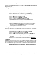
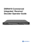
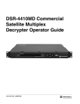
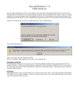
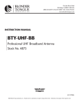
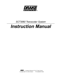
Showtime East Digital
IRD Rollout DSR 4410
Installation Instructions
Date: 12/07/2006
Copyright 2005 by Motorola Corporation.
All rights reserved
No part of this publication may be reproduced in any form or by any means or used to make any derivative work (such as translation,
transformation or adaptation) without written permission from Motorola. Motorola reserves the right to revise this document and to make
changes in content from time to time without obligation on the part of Motorola to provide notification of such revision or change.
Motorola provides this guide without warranty of any kind, implied or expressed, including, but not limited to the implied warranties of
merchantability and fitness for a particular purpose. Motorola may make improvements or changes in the product(s) and /or the
program(s) described in this document at any time.
Motorola Corporation
101 Tournament Drive
Horsham, PA 19044
All information contained in this document is Proprietary to Motorola Inc. and is disseminated solely for the
convenience and support of its customers.
Showtime East Digital IRD Rollout DSR 4410 Installation Instructions
TABLE OF CONTENTS
1. Introduction ...............................................................................................................................................................3
2. DSR-4410 Integrated Receiver Decoder ..................................................................................................................3
2.1 DSR-4410 Front Panel.........................................................................................................................................3
2.2 DSR-4410 Rear Panel..........................................................................................................................................3
3. Installation Information .............................................................................................................................................4
3.1 Physical Installation.............................................................................................................................................4
3.2 Connecting the Satellite Feed ..............................................................................................................................5
3.3 Connecting Video and Audio Outputs.................................................................................................................5
3.4 Satellite and Channel Information Chart .............................................................................................................5
3.5 Tuning Satellite Feed...........................................................................................................................................6
3.6 Configuring Channel Parameters.........................................................................................................................6
3.7 CUE Tones ..........................................................................................................................................................6
3.8 Retrieving Unit Address ......................................................................................................................................7
3.9 Calling for IRD Authorization.............................................................................................................................7
4. Basic Troubleshooting tips for no DigiCipher/Signal lock........................................................................................7
5. Warranty Information ................................................................................................................................................7
TABLE OF FIGURES
Figure 1: DSR-4410 Front Panel ...................................................................................................................................3
Figure 2: DSR-4410 Rear Panel ....................................................................................................................................4
Figure 3: Satellite and Channel Information Chart........................................................................................................5
All information contained in this document is Proprietary to Motorola Inc. and is disseminated solely for the
convenience and support of its customers.
2/7
Showtime East Digital IRD Rollout DSR 4410 Installation Instructions
1. Introduction
Motorola has begun the IRD Rollout project for the Showtime East feed. This shipment includes one Motorola
DSR-4410 Integrated Receiver Decoder (IRD), which is compatible with the Showtime East digital conversion,
dependent upon your Showtime contractual agreement. This installation guide will provide you with an
understanding of how to physically install, configure and activate this IRD for the digital conversion.
NOTE: Showtime Networks will begin service interruptions on The Movie Channel East analog
service March 5, 2007. Service interruptions may be in the form of a banner scrolling across
the screen and/or loss of video. These service interruptions may continue and grow in
frequency until the Analog service, located on Satellite Galaxy 14, Transponder 24, has been
discontinued. To avoid a service interruption please have your DSR-4410 installed and
authorized before February 26, 2007.
2. DSR-4410 Integrated Receiver Decoder
Showtime and Motorola have set up a toll-free number to help with your request, installation, authorization, and
technical assistance. Once you receive your new IRD, technical questions concerning installation or operation
should be directed to Motorola at 1-866-276-4327.
Technical information found in this installation guide can also be found in Motorola’s, “DSR-4410 DigiCipher
II Commercial Integrated Receiver Decoder Operator Guide.”
2.1 DSR-4410 Front Panel
Figure 1: DSR-4410 Front Panel
•
•
•
•
•
•
•
•
•
•
PORT 0 LED
PORT 1 LED
RELAY LED
ALARM LED
LCD Front Panel Display
AUTHORIZED LED
BYPASS LED
SIGNAL LED
DOWNLOAD LED
Keypad with directional and ENTER buttons
2.2 DSR-4410 Rear Panel
All information contained in this document is Proprietary to Motorola Inc. and is disseminated solely for the
convenience and support of its customers.
3/7
Showtime East Digital IRD Rollout DSR 4410 Installation Instructions
Figure 2: DSR-4410 Rear Panel
3. Installation Information
•
•
Follow steps 1 through 32 to complete the DSR-4410 installation and authorization.
For questions regarding the Showtime East IRD installation or DSR-4410 IRD, please contact
Motorola at 1-866-276-4327.
3.1 Physical Installation
1.
Install the receiver in a 19-inch universal rack and connect the power cord to an
available AC outlet.
2.
Apply AC power to the unit. All LED’s on the DSR will go through a self-test and the
LCD will temporarily display “MOTOROLA DSR4410” and the firmware version.
Once the unit has completed the power up sequence, it will display the Main Menu as
shown below:
◄ ►E
•
•
→Install
DSR4410
→Channel
→Status
→Diag
When the unit has power, the front panel Liquid Crystal Display (LCD) will display
characters, and at least one Light Emitting Diode (LED) should be lit. If the LCD
backlight is not on, press any front panel directional button (3456Enter) to light.
If the unit fails to power up properly contact Motorola at 1-866-276-4327.
All information contained in this document is Proprietary to Motorola Inc. and is disseminated solely for the
convenience and support of its customers.
4/7
Showtime East Digital IRD Rollout DSR 4410 Installation Instructions
3.2 Connecting the Satellite Feed
The DSR-4410 provides power on the L-Band (RF) inputs for an LNB. Use an inline (barrel) DC block or DC
block splitter connection to prevent conflict with the LNB voltage that may already be present in the system. If
you do not use a DC Block, the following may occur after you apply power and connect the satellite feed:
•
•
•
The front panel controls do not work
You cannot navigate through the menus
All front panel lights are off.
3.
For a single polarity L-Band satellite connection, connect the coax from the LNB
(vertical) to Port 0 on the rear panel of DSR-4410. It is a good practice to record and
label which port(s) and polarities are connected to the LNB. Labeling the coax at the
rear panel is also a good practice.
3.3 Connecting Video and Audio Outputs
4.
To view video and On-Screen Diagnostics during installation, connect the OSD Video
Output on the unit to a 75 Ohm video monitor. After the unit is authorized and
outputting the desired service, reconnect the Video Output to the channel modulator.
5.
To listen to audio during installation, connect the audio outputs to a local amplifier and
speaker. A standard stereo system will suffice, but the lack of differential audio inputs
may make the audio seem degraded. After the unit is authorized and outputting the
desired service, reconnect these outputs to the channel modulator. Since these are
differential pairs, it is recommended to use two pair of shielded audio cables rather than
the single wire and shield type. For best quality audio, please take care to ground the
shield on both the IRD GND terminal and at the channel modulator end.
For services transmitted in stereo and used in your plant as stereo, connect the Left
Audio Out terminals (L+ and L-) to the left audio inputs on the channel modulator, and
connect the Right Audio out terminals (R+ and R-) to the right audio inputs on the
channel modulator. For services transmitted as a single mono, connect the Left Audio
out terminals (L+ and L-) to the audio inputs on the channel modulator. Right Audio out
terminals (R+ and R-) will also contain the single mono.
3.4 Satellite and Channel Information Chart
The Satellite and Channel Information Chart below, Figure 3, provides detailed information for the digital
Showtime East IRD Roll-out multiplex. This information is required to properly configure the DSR-4410 IRD.
Network
Satellite
Transponder
L-Band Freq.
Polarization
Satellite Orbital
Location
Symbol Rate
FEC Rate
Transmission
System
Virtual
Channel
Table
Virtual
Channel
MPEG
Service
Number
Video
Audio 1
Audio 2
Audio 3
Showtime
East
AMC 11 Transponder 19
1075 MHz
Vertical
131 Degrees
W. Longitude
19.51 Mb/s
¾ Combined
0183
100
1
NTSC
N/A
Figure 3: Satellite and Channel Information Chart
All information contained in this document is Proprietary to Motorola Inc. and is disseminated solely for the
convenience and support of its customers.
5/7
Showtime East Digital IRD Rollout DSR 4410 Installation Instructions
Please note that the digital carrier is on AMC 11, Transponder 19, a different satellite and transponder than
the current analog signal.
3.5 Tuning Satellite Feed
6.
7.
8.
9.
10.
11.
12.
13.
14.
15.
16.
17.
18.
19.
20.
21.
From the Main Menu use the ◄►to select Install, press ENTER.
Use the ▼▲ buttons to select the MANUAL TUNE menu
From MANUAL TUNE menu, verify Input = Port 0 and Mode = Xpndr
Use the ◄► buttons to select Xpndr, press ENTER.
Use the ▲▼ buttons to change the transponder to 19, press ENTER to save.
From the MANUAL TUNE menu verify the L-Freq = 1075.00 MHz (Xpndr19)
Use the ◄► buttons to move the cursor to MANUAL TUNE.
Use the ▼button to move the cursor to the MODULATION.
Use the ◄► buttons to select Mode, press ENTER.
Use the ▲▼ buttons to select DCII-MAN, press ENTER.
Use the ► button to select Symbol Code Format, press ENTER.
From the Modulation Menu Press the ► twice to highlight Symbol 19.51, press
ENTER.
Use the ▼▲ buttons to select ¾ combined, press ENTER to save.
Press ►to move the cursor to MODULATION.
Press ENTER to display the Main Menu.
Wait for the SIGNAL green LED to illuminate. This can take up to 2 minutes. Do not
proceed to the next step if the SIGNAL LED does not come on; proceed to Basic
Troubleshooting Tips for No Signal lock in Section 4.
3.6 Configuring Channel Parameters
Before viewing video and audio on the DSR-4410 IRD, the operator must select the correct Virtual Channel
Table (VCT) ID and Channel number. In addition the IRD must be authorized for the intended service. Follow
the steps below to enter the correct VCT ID and Channel number.
22.
23.
24.
25.
26.
27.
From the Main Menu use the ◄►button to select Channel, press ENTER.
Use the ► button to move the cursor to VCT, press ENTER.
Use the ▼▲◄► buttons to change the VCT number to 0183, press ENTER to save.
Use the ► button to move the cursor to Chnl, press ENTER.
Use the ▼▲◄► buttons to change the channel number to 0400, press ENTER to save.
Use the ◄►button to move the cursor to CHANNEL, Press ENTER to return to the
Main Menu.
28. If you receive an error when selecting the channel contact Motorola at 1-866-276-4327.
3.7 CUE Tones
The DSR-4410 will be able to generate cue tones when commanded over the satellite link. If these internally
generated cue tones are used, connect the 600 Ohm differential Cue Tone+ and Cue Tone- terminals on the
DSR-4410 to the device that will be accepting the tones. The cautions on cable and grounding noted in the
audio instructions above also apply to cue tones.
Note: Showtime East feed runs commercial free. Please proceed to section 3.8.
All information contained in this document is Proprietary to Motorola Inc. and is disseminated solely for the
convenience and support of its customers.
6/7
Showtime East Digital IRD Rollout DSR 4410 Installation Instructions
3.8 Retrieving Unit Address
The Unit Address can be obtained from a sticker on the bottom of unit, on the outside of the shipping carton, or
from the front panel display. In addition, the Unit address can be retrieved through the IRD menus.
29. From main menu use the ◄► to highlight Diagnostics, press ENTER then use ▼
button to view the Unit Address.
30. Provide Unit Address to Motorola for Authorization.
31. Once the unit is authorized, the AUTHORIZED LED should illuminate.
3.9 Calling for IRD Authorization
Motorola will administer network authorizations for your IRD Monday through Friday 8 AM to 8PM EST.
32. For authorization have your old VideoCipher Unit Address(s), new DigiCipher Unit
Address(s), user name and password (contained in affiliate letter mailed to you) and
contact Motorola via toll free, 1-866-276-4327. A Motorola IRD Specialist will
authorize your new DigiCipher Unit Address. Showtime will de-authorize your old
VideoCipher, 5 business days after initial authorization of your new DigiCipher unit. If
you need to have the analog feed on longer, please let the IRD Rollout Center
Representative know.
4. Basic Troubleshooting tips for no DigiCipher/Signal lock
•
•
•
•
Confirm the correct signal cable (AMC 11 Vertical) is connected to the L-Band input Port 0.
In the Installation>Modulation menu, verify Mode = DCII-MAN, Symbol=19.51, Code=3/4, and
Format=combined.
Verify Input Port 0 and L-Band Freq 1075 MHz is selected in the Installation>Manual Tune menu.
For additional help contact Motorola at 1-866-276-4327.
5. Warranty Information
Motorola's Defect Return Policy requires that Motorola verify that the equipment is defective. Motorola
Standard Warranty is that if a DSR-4410 (shipped for this project) is found to be defective within 45 days from
when the unit was shipped out of the Motorola facility and needs to be replaced, Motorola will supply shipping
for the new and return of the defective unit free of charge. Prior to the Showtime signal interruption, the new
unit will not be shipped until the defective unit has been returned to Motorola. This includes the customer
sending the unit in for repair.
All information contained in this document is Proprietary to Motorola Inc. and is disseminated solely for the
convenience and support of its customers.
7/7