1
0
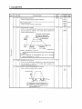
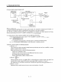
Safety Instructions
(Always read these instructions beforeusing the equipment.)
Do not attempt to install, operate, maintain or inspect the servo amplifier and servo motor until you have read
through this Instruction Manual, Installation guide, Servo motor Instruction Manual and appended documents
carefully and can use the equipment correctly.Do not use the servo amplifier and servo motor until you have a
full knowledge of the equipment, safety information
and instructions.
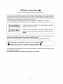
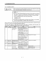
In this Instruction Manual,the safety instruction levelsare classified into "WARNING" and "CAUTION".
11-
Indicatesthatincorrect
handling may cause hazardousconditions,,
resulting in death or severeinjury.
Indicatesthatincorrect
handling may causehazardousconditions,,
resulting in medium or slight injury to personnel or may cause physical
damage.
Note that the CAUTION level may lead to a serious consequence according to conditions. Please follow the
to personnel safety.
instructions of both levels because they are important
What must not be done and what must be done
are indicated by the following diagrammatic symbols:
~~
8:
Indicates what must not be done.For example, "No Fire" is indicated by .@
0:Indicates what must be done.For example, groundingis indicated by .e
In this Instruction Manual, instructions at a lower levelthan the above, instructions for other functions, and so
on are classified into "POINT".
After reading this installation guide, always
keep it accessible tothe operator.
A-
1
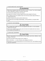
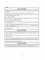
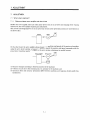
1. To prevent electric shock, note the following:
AWARNING
Before wiring orinspection, switch power offand wait for more than10 minutes. Then,confirm the voltage is
safe with vottagetester. Otherwise, you may get an electric shock.
Connect the servoamplifier and servo motor to ground.
Any person who isinvolved in wiring and inspection should be fully competent to
do the work.
Do not attempt to wirethe servo amplifier and servo motor until they have been installed. Otherwise, you
may get an electric shock.
Operate the switcheswith dry hand to prevent an electric shock.
The cables should not be damaged, stressed loaded,, or pinched. Otherwise, you may get an electric
shock.
2. To prevent fire, note thefollowing:
A CAUTION
Do not install the servo amplifier, servo motor and regenerative brake resistoron or near combustibles.
Otherwise afire may cause.
When the servo amplifier has become faulty, switch off the main servo amplifier power side. Continuous
flow of a large currentmay cause a fire.
3. To prevent injury, note the follow
A CAUTION
Only the voltagespecified in the Instruction Manual should be applied to each terminal,, Otherwise,,
a burst,,
damage,, etc. may occur.
Connect theterminals correctly to prevent a burst,, damage,, etc.
Ensure that polarity (+,-) is correct. Otherwise, a burst, damage, etc. may occur.
During power-on or for some time after power-off, do not touch the servo motor. Their temperatures may be
high and you may get burnt.
A- 2
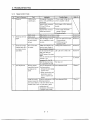
4. Additional instructions
The following instructions should also be fully noted.Incorrect handling may cause a fault, injury, electric shock,
etc.
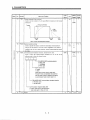
1) Transportation and installation
A CAUTION
Transport the products correctly according to their weights.
Stacking in excessof the specified number of products is not allowed.
Do not carrythe motor by the cables, shaftor encoder.
Do not hold the frontcover to transportthe controller. The controller may drop.
Install the servo amplifier in a load-bearing place in accordance with the Instruction Manual.
Do not climb or stand on servo equipment.Do not put heavy objects on equipment.
The controller and servo motor must be
installed in the specified direction.
Leave specified clearances betweenthe servo amplifier and control enclosure wallsor other equipment.
Do not install or operate the servo amplifier and servo motor which has been damaged or has any parts
missing.
Provide adequate protection topreventscrewsandotherconductivematter,
oil and other combustible
matter from enteringthe servo amplifier.
Do not drop orstrike servo amplifier or servomotor. Isolate from all impact loads.
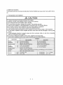
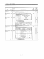
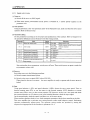
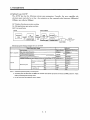
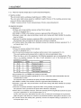
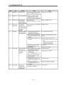
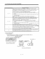
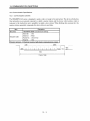
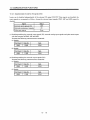
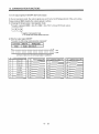
Use the servo amplifier and servo motor underthe following environmental conditions:
Conditions
Environment
Servo Amplifier Servo Motor
0 to +55 (non-freezing)
0 to 4 0 (non-freezing)
32 to 131 (non-freezing)
32 to 104 (non-freezing)
90%RH or less (non-condensing)
80%RH or less (non-condensing)
Storage
temperature
-20 to +65 (non-freezing)
-15 to +70 (non-freezing)
4to 149 (non-freezing)
5 to 158 (non-freezing)
Storage humidity
90%RH or less (non-condensing)
Ambience
Indoors (no direct sunlight) Free from corrosive qas, flammable gas, oil mist, dust and dirt
Ambient
temperature
I
..
Ambient humiditv
~
~~
~
Max. 1OOOm (3280 ft) above sea level
Altitude
Vibration
[m/s2]
5.9 (0.6G) or less
HC-AQ Series
X . Y : 19.6 {2G)
[Ws2]
19.4 or less
HC-AQ Series
X . Y : 64
A-
3
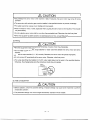
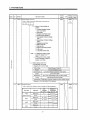
A CAUTION
Securely attach the servo motor to the machine. If attach insecurely, the servo motor maycome off during
operation.
The servo motor with reduction gearmust be installed in the specified direction prevent
to
oil leakage.
For safety of personnel, always cover rotatingand moving parts.
Never hit the servo motor or shaft, especially when coupling the servomotor to the machine. The encoder
may become faulty.
Do not subject the servo motor shaftto more than the permissible load. Otherwise,the shaft may break.
When the equipment has been stored for an extended period
of time, consult Mitsubishi.
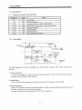
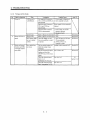
(2) Wiring
A CAUTION
Wire the equipment correctly and securely. Otherwise,
the servo motor may misoperate.
Do not install a power capacitor, surge absorber or radio noise filter between the
amplifier.
servo motor and servo
Connect the output terminals (U,V, W) correctly. Otherwise, the servo
motor will operate improperly.
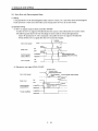
Do not connect AC power directly tothe servo motor. Otherwise, a faultmay occur.
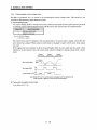
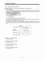
The surge absorbing diode installed on the DC output signal relay must be wired in the specified direction.
Otherwise, the emergency stop and other protective circuits may not operate.
Servo
Amplifier
(24VDC)
Control
output
J
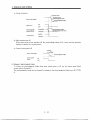
(3) Test run adjustment
A CAUTION
Before operation, check the parameter settings. Improper settings may cause some machines to perform
unexpected operation.
The parameter settings must not be changed excessively. Operation will be instable.
A- 4
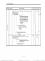
A CAUTION
Provide an external emergency stop circuitto ensure that operationcan be stopped and power switched off
immediately.
Any person who is involvedin disassembly and repair should be fully competent to do
the work.
Before resetting an alarm, make sure that the run signal is off to prevent an accident. A sudden restart is
made if an alarm is reset withthe run signalon.
Do not modify the equipment.
Use a noise filter, etc. to minimize the influence of electromagnetic interference, which may be caused by
electronic equipment used near the servo amplifier.
Use the servo amplifier with the specified servo motor.
The electromagnetic brake on the servo motor is designed to hold the motor shaft and should not be used
for ordinary braking.
For such reasons as sewice life and mechanical structure (e.g. wherea ballscrew and the servo motor are
coupled via a timing belt), the electromagnetic brake may not hold the motor shaft.To ensure safety, install
a stopper on the machine side.
(5) Corrective actions
L
!
A CAUTION
When it is assumed that a hazardous condition may take place at the occur due to a power failure or a
product fault,use a servo motor withelectromagnetic brake or anexternal brake mechanism for the
purpose of prevention.
When any alarm has occurred,eliminateitscause,ensuresafety,anddeactivate
restarting operation.
the alarm before
When power is restored after an instantaneous power failure, keep away from the machine because the
machine may be restarted suddenly(design the machine so that it is secured againsthazard if restarted).
(6) Maintenance, inspection and parts replacement
.
L
A CAUTION
With age, the electrolytic capacitor will deteriorate. To prevent a secondary accident due to a fault, it is
recommended to replace the electrolytic capacitor every10 years when used in generalenvironment.
A-
5
<
(7) Disposal
I
A CAUTION
2
I
Dispose of the product as generalindustrial waste.
(8) General instruction
To illustrate details, the equipmentin the diagrams of this Instruction Manual may have been drawn without
covers and safety guards.When the equipment is operated, thecovers and safety guards must be installed
as specified. Operation must be
performed in accordance with this Instruction Manual.
A-
6
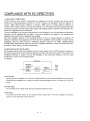
COMPLIANCE WITH EC DIRECTIVES
I . WHAT ARE EC DIRECTIVES?
l'he EC Directives were issued to standarche the regulations of the EU countries and ensure smooth
iistribution of safety-guaranteed products. In the EU countries, the Machmery Directive
(effective in
January, 1995), EMC Directive(effective inJanuary, 1996) and Low VoltageDirective (effective in
January, 1997) of the EC Directives require that productsto be sold should meet their fundamental safety
requirements and carry the CE marks (CE markmg). CE marlung applies to machmes and equipment into
which servo amphfiers have been installed.
The servo amphfiersdo not function independently but are designed
for use with machines and equipment.
I'herefore, the CE markmgdoesnotapply
to theservoamplifiersbutapplies
to themachmesand
3quipment into whch theservo amphfiers are installed.
This servoamphfierconforms to the standards related to the Low VoltageDirective to fachtate CE
markmg on machnes and equipment into whch the servo amphfierswdl be installed. To ensure ease of
compliance
with
the
EMC Directive, Wtsubish Electric prepared
the
"EMC
INSTALLATION
GUIDELINES" (IB(NA)67310) w h c h provides servo ampMer installation, control box malung and other
procedures. Please contact your sales representative.
2. PRECAUTIONS FOR COMPLIANCE
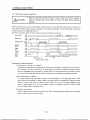
The standard models of the servo amphfier and servo motorcomply with the EN Standard. In additionto
the instructions providedin t h s Instruction Manual, also follow the instructions below. If the model is not
specficallydescribed to comply withtheENStandardin
t h s InstructionManual,ithasthesame
specfications as thoseof the standardmodels:
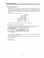
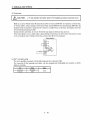
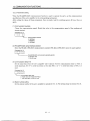
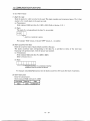
(1) Structure
Control box
I
I
Reinforced
insulation type
I 1supply 1
motor
amplifier
1"" "'"'I
(2) Environment
Operate the servo amphfiera t or above the contamination level 2 set forth in IEC664. For this purpose,
install the servo amphfier in acontrol box whch is protected against water, oil, carbon, dust, dwt,etc.
(IP54).
(3) Power supply
Use a 24VDC power supply whch hasbeen insulation-reinforced in I/O.
(4) Grounding
To prevent a n electric shock, fit the supplied earth terminal
connect it to the earth (E) of the control box.
A- 7
(E) to the servo ampM1er and always
(5) Auxiliary equipment and options
(a) The circuit protector used should
described in Section 12.2.2.
be the EN or IEC Standard-compliant product
of the model
(b) The sizes of the cables described in Section 12.2.2 meet the following requirements. To meet the
other requirements, follow Table 5 and Appencbx C in Eh'60204.
Ambient temperature: 40 (104) ["C ("F)]
Sheath: PVC (polyvinyl chloride)
Installed on wall surface or open table tray
(6)Performing EMC tests
When EMCtests are run on a machme/device into whch theservo amphfier hasbeen installed, it must
conform to the electromagnetic compatibhty (immunity/emission) standards after it has satisfied the
operating environmentJelectrical equipmentspecifications.
For the other EMC Directive g u i d e h e s on the servo amphfier, refer to the "EMC INSTALLATION
GUIDELINES".
CONFORMANCE WITH UUC-UL STANDARD
The standard modelsof the servo amphfier and servomotor comply with theULIC-UL Standard.
Unlessotherwisespecdied,the
h a n d h g , performance,specdications, etc. of the ULIC-UL Standardcompliant models are the same as those
of the standardmodels.
When using 24VDcpower supply, options and a d a r y equipment, use those w h c h conform to the UUCCL Standard.
A-
9
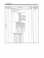
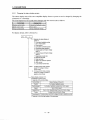
CONTENTS
1. FUNCTIONS AND CONFIGURATION
l.lIntroduction ...........................................................................
1.2Function.st
...........................................................................
1 . 3 M o d e l C o d e D e b t i o n ..................................................................
1.4CombinationwithServoMotor ...........................................................
1.5PartsIdent.cati
on .....................................................................
1.6 Servo Systemwith A d a r y Equipment ..................................................
2. INSTALLATION
2- 1 to 2- 4
2 . 1 E n ~ o n m e n ~ c o n & t i o n...............................................................
s
2.2 Installation
clearances
and
.....................................................
2.3 K~~~ outforeign
..............................................................
2.4Cablest ress ............................................................................
2.5 Using the DIN rdfor installation ........................................................
~~~
~~~
1- 1
1-2
1-3
1-3
1- 4
1- 5
2- 1
2- 2
2- 3
2- 3
2- 4
~
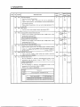
3. SIGNALS AND WIRING
3- 1 to 3-46
3.1 Standard connectionexample............................................................
3.1.1 position control mode AD75pn (AlSD75pO) ..........................................
3.1.2 Speed control mode
..................................................................
3~1.3Torquecontrolmode
.................................................................
3.2 Internal Connection Diagram of Servob p f i e r ...........................................
3.3I/OSlgnal .............................................................................
and
Connectors
3.3.1
..................................................
3.3.2 Signal explanations ................................................................
3.4 Detailed Description of the Sign& ......................................................
3.4.1 positioncontrolmode ...............................................................
3.4.2Speedcontrolmode .................................................................
3 ~ 4 ~ 3 ~ o r q u e c o n ~er ................................................................
o~mo~
3.4.4 position/speed control change mode..................................................
3.4.5 Speed/brquecontrolchange mode ...................................................
3.4.6 Torque/position controlchange mode .................................................
3.5AlarmOccurrenceTimingChart ........................................................
3.61nterfaces .............................................................................
3.6.1 C o m m o n h e ......................................................................
3.6.2 Detailed descriptionof the interfaces .................................................
3.7 Input powerSupply Circuit.............................................................
3.7.1 Connectionexample ................................................................
3.7.2 Explanation of sign& ..............................................................
3.7.3 power-onsequence .................................................................
3.8 Servo Motor with ElectromagneticBrake ................................................
3.9Groundi ng ............................................................................
3.10 Instructions for the 3M Connector ......................................................
1
3- 2
3- 2
3- 4
3- 5
3- 6
3- 7
3- 7
3- 10
3- 19
3- 19
3- 24
3- 26
3- 29
3- 31
3- 33
3- 34
3- 35
3- 35
3- 36
3- 40
3- 40
3- 41
3- 41
3- 43
3- 45
3- 46
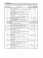
14. OPERATION
4- 1 to 4- 61
4.1 men
Switchng power On for the First T h e .............................................
4.2st artup ................................................................................
4.2.1 Selectionof control mode .............................................................
4.2.2 positioncontrolmode ................................................................
4,2.3Speedcontrolmod e ..................................................................
4.2.4Torquecontrolmod e .................................................................
4.3 M ~ t i d r o p C o m m u ~ con
a t ...............................................................
i
4- 1
4- 2
4- 2
4- 2
4- 4
4- 5
4- 6
~~
15. PARAMETERS
5- 1 to 5- 211
5.1 parameterkst .........................................................................
5.1.1 parameter
h b i t ..............................................................
5.1.2 k s k ...............................................................................
5 .2DehiledDescfiption ...................................................................
5.2. lElectronicgear .....................................................................
5.2.2 Changing the
&play Screen ..................................................
5- 1
5- 1
5- 2
5- 18
5- 18
6 - 20
5.2.3 Using forwardreverse rotation stroke end to change the stopping pattern............... 5- 21
5.2. 4iUarmhstorycl
ear ................................................................. 5- 21
6. DISPLAY AND OPERATION
6-1 to6- 15
6. lDisplayFlowchart ......................................................................
6. 2StatusDisplay.........................................................................
6. 3Diagnosticmod
e ........................................................................
6.4Alarmmode ............................................................................
6.5Parametermod e ........................................................................
6.6 External I/O signal &splay ..............................................................
6.7 Output signal forced output (DO forced output) ...........................................
6.8Testoperationmode ...................................................................
6.8.1Modechange ......................................................................
6.g.2Jogoperation ......................................................................
6 ~ g ~ 3 p o s ~ t i o ~ n g o p e r ...............................................................
ation
6.~ ~ 4 M o ~ o r . ~ e s son
o p................................................................
er~~~
7. ADJUSTMENT
Is
6- 2
6- 4
6- 5
6- 6
6- 8
6- 11
6- 12
6- 12
6- 13
6- 14
6- 15
7- 1 t O 7 - 10
..............................................................
7.1.1 Differencebetweenservoamphtierandotherdrives ....................................
~ ~ ~ ~ ~ ~ a s ~ c s o f ~ ~ e............................................................
servosys~m
7.2GainAdjustment .......................................................................
7.2.1 parameters
for gain adjustment ...............................................
7,2.2Block&agram ......................................................................
i.2,3~?latlsautotuning? ................................................................
7.1 What
6- 1
Adjustment?
2
....
.
.
7- 1
7- 1
7-2
7-3
7-3
7-3
7-4
7 . 3 Gain Adjustment by Auto Tuning ........................................................
'i.3.lAdjustmentmethod .................................................................
'i.3.2V.dcon.tions
.....................................................................
7 .4ManudG&Adjustment
...............................................................
7.4.1 When
ngi&ty is low .........................................................
7.4.2 When the machne vibrates dueto machne resonance frequency- ........................
7.4.3 h a d inertia momentis 20 or
times ..............................................
7.4.4 When
the s e t t h g t h e ....................................................
7.4.5 When thesamegain is used fortwo or more axes * * * * . * . *
* * *
.*
* *
* * * *
7 . 5 SLght Vibration SuppressionControl ....................................................
*
8. INSPECTION
7-5
7-5
7-5
7-6
7 -6
7-7
7 -8
7-9
7 - 10
7 - 10
8- 1
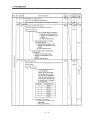
19. TROUBLESHOOTING
to
9-1
9- 11
9.1TroubleatStart-U .....................................................................
9.1.1 positioncontrol mode ................................................................
g.1.2Speedcontrolmod e ..................................................................
g ~ ~ ~ 3 ~ o r q u e c o n e~.................................................................
ro~mo~
9.2 When Alarm or Warning Has Occurred ...................................................
9.2.1 Alarms and Warning list .............................................................
9,2.2~med,esforal-s
.................................................................
9.2,3Reme&esforWa-gs
.............................................................
9- 1
9- 1
9- 4
9- 5
9- 6
9- 6
9- 7
9- 11
10. SPECIFICATIONS
10- 1 to 10- 4
10.1 Servo b p m e rStandard Specifications ................................................
10.2 Outline Dimension Drawings ..........................................................
1 0 . 2 . 1 S e r v o a m p ~ e r s ..................................................................
10.2,2Connectors .......................................................................
I11. CHARACTERISTICS
10- 1
10- 2
10- 2
10- 3
11- 1 to 11-31
11.1 Overload protectionCharackfistics ....................................................
11.2 DynamicBrake Characteristics ........................................................
1 1 . 3 E n c o d e r C a b l e F l e - g ~ e ............................................................
. OPTIONS
AUXILIARY
EQUIPMENT
AND
11- 1
11-2
11- 3
12- 1 to 12- 14
12.1Optioris ..............................................................................
12.1.1 Cablesandconnectors .............................................................
12.1.2 Junctionterminal block (MR-TBzO) .................................................
12.1.3 ~ e r v o c o ~ g u r a ~ ~ o n s s o f ......................................................
tware
12,2Aux.arq.Equipment ................................................................
12.2,1Recommended wires ..............................................................
1 2 . 2 , 2 C ~ c ~ t p r o t e c t o.................................................................
r
3
12- 1
12- 1
12- 6
12- 8
12- 10
12- 10
12- 10
12.2.3&lays ..........................................................................
12.2.4 Noise reduction t e c h q u e s ........................................................
13. COMMUNICATION FUNCTIONS
12- 11
12- 11
13- 1 to 13- 26
13.1co~guration ........................................................................
1 3 , 1 . 1 ~ ~ - 4 2 2..............................................................
~ ~ ~ ~ ~ t i ~ ~
RS-232C
13.1.2
.............................................................
13.2 Comm-cation
Spedcations .........................................................
13.2.1Comm-cationoverview
..........................................................
13.2,2parametersetti ng .................................................................
1 3 . 3 ~ .............................................................................
~ ~ ~ ~ ~ 1
13.4CharacterCod es ......................................................................
13.5ErrorCod es ..........................................................................
13.6Checksum ...........................................................................
13.7The-Out@eration ..................................................................
13.8&tryOperation ......................................................................
13.91niti~~
ont i.........................................................................
13.10 Comm-cation
procedure Example ...................................................
13.11CommandData
No. k s t ........................................................
13.11.1Readcommands ................................................................
13.11,2Writecommand ................................................................
13.12 D e M e d Explanations of Commands .................................................
1 3 . 1 2 . 1ataprocessing
~
.................................................................
1 3 . 1 2 . 2 ~ h t ~ ~..................................................................
& ~ ~ l ~ ~
1 3 . 1 2 . 3arameter
~
......................................................................
13.12.4 External I/O pin statuses (DIO hagnosis) .........................................
13.12.5 Disable/enable of external I/O signals (010) .......................................
13.12.6 External input signalOMOFF (Test operation) ....................................
13.12.7Testoperationmode .............................................................
13.12.8 Outputsignal pin ON/OFF (DO forced output) * * * . * . . . . * * . * * . *
*
.*
1 3 . 1 2 , g ~ l ~ ory
~ h ...................................................................
l~t
13.12,10current alarm .................................................................
13.12.11 Othercommands ..............................................................
4
.
.
.
*
13- 1
13- 1
13- 2
13- 3
13- 3
13- 4
13- 5
13- 6
13- 7
13- 7
13- 8
13- 8
13- 9
13- 9
13- 10
13- 10
13- 11
13- 13
13- 13
13- 15
13- 16
13- 18
13- 19
13- 20
13- 21
13-23
13- 24
13- 25
13- 26
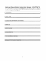
Optional Servo Motor Instruction ManualCONTENTS
The rough table of contents of the optional MELSERVO Servo Motor Instruction Manual is introduced
here for your reference. Note that the contentsof the Servo Motor Instruction Manual are not included
in the ServoA m p a e r Instruction Manual.
1. INTRODUCTION
I
2. INSTALLATION
I
13. CONNECTORS USED FOR SERVO MOTOR WIRING
1
4. INSPECTION
I
5. SPECIFICATIONS
1
6. CHARACTERISTICS
I
7. OUTLINE DIMENSION DRAWINGS
I
1
18. CALCULATION METHODS FOR DESIGNING
5
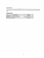
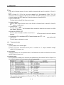
About the Manuals
T h s Instruction Manual and theMELSERVO Servo MotorInstruction Manual are requiredd y o u use the
General-Purpose AC servo MR-JZ-03A5for the first time. Always purchase them and use the
MR-JZ-03A5
safely.
I Relevant manuals I
Manual Name Manual
MEISERVO-J2-Jr
Series
Installation
Guide
No.
IB(NA)67426
MELSERVO Servo Motor Instruction Manual
S H ( N A ) 3 1 8 1 F e r - Cor later)
EMC Installation Guidelines
IB(NA)67310
6
1. FUNCTIONS AND CONFIGURATION
1. FUNCTIONSANDCONFIGURATION
1.1 Introduction
The MELSERVO-J2-Jr series general-purpose AC servo has been developed as an ultracompact, s m d
capacity servo system compatible with theMELSERVO-J2 series 24VDC power supply. It canbe used in a
wide range of fields from semiconductor equipment
to small robots, etc.
The input signalsof the servo amphfier control system are
compatible with those of the MR-J2-OA.
As the standard modelscomply with the EN Standard * W C - U L Standard, they canbe used satisfactorily
in various countries.
The MR-J2-03A5 servoamphfier canbe easily installed to a control box with a DIN rail.
The power supply/electromagnetic brake and encoder of the servo motor can be wired easily with a single
cable.
Using a personal computer where the Servo
Configuration software has been installed, you can make
parameter setting, status &splay, etc.
Also, you can use the RS-422 communication functionto set upto 32 axes of servo amphfiers.
Thecompatibleservo motors have acheved the smallest
28mm-boreflangesize in this class and are
further equipped with encodersof 8192 pulsedrev (incremental) resolution.
1- 1
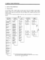
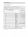
1. FUNCTIONS AND CONFIGURATION
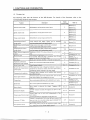
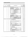
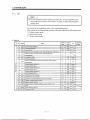
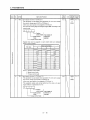
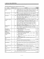
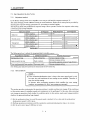
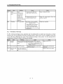
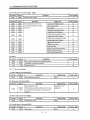
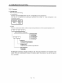
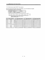
1.2 Function List
The following table lists the functions of the MR-J2-03A5. For details of thefunctions, refer tothe
corresponding chapters and sections.
External IiO display
.\utomatlc VC offset
1- 2
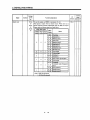
1. FUNCTIONS AND CONFIGURATION
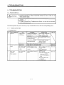
Function
Servo configuration
software
Alarm code output
(Note)
Control Mode
Description
Using a personal
computer,
parameter
setting,
test
operation, status display, etc. canbe performed.
If an alarm has occurred, the corresponding alarm number
is output in 3-bitcode.
Refer To
P, S, T
Section 12.1.3
P, S, T
Section 9.2.1
Note: P: Position control mode, S: Speed control mode, T: Torque controlmode
P/S: Positiodspeed control change mode, SR: Speed'torque control change mode,TIP: Torque/position control change mode
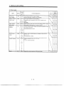
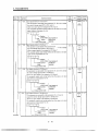
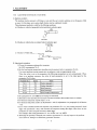
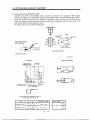
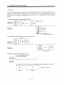
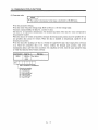
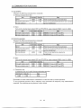
1.3 Model Code Definition
(1) Rating plate
I
Model
llRJ2-03A5
Applicable power supply
-
Rated output current
-L_ Serial number
(2) Model
I
l
i
24VDC power supply specification
General-purpose
interface
Rated output 30m
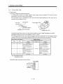
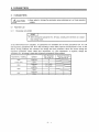
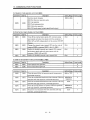
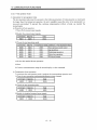
1.4 Combination withServoMotor
The HC-AQ series servo motors can be used. The same combinations apply to the servo motors provided
with electromagnetic brakes and reduction gears.
I
Servo
Amplifier
Servo
motor
HC-AQ0135D
MR-J2-03A5
HC-AQ0235D
HC-AQ0335D
1- 3
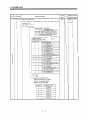
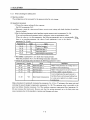
1. FUNCTIONS AND CONFIGURATION
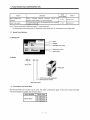
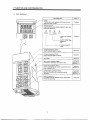
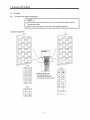
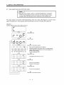
1.5 Parts Identification
Refer To
Display
The four-digit, seven-segment LED shows the servo
status and alarm number.
Chapter6
Operation section
Used to perform status display, diagnostic, alarm and
parameter operations.
MODE
1
UP
DOWN
SET
'-used to set parameter
data.
Chapter6
Used to change the
display or data in each
mode.
I
Used to change the
mode.
~
~~
I/O signal connector (CN1A)
Used to connect digital I/O signals.
Section3.3
I/O signal connector (CN16 )
Used to connect digital I/O signals.
Section3.3
Name plate
Sectionl.3
Servo motor connector (CNP2)
Connector for connection of the servo motor.
Section3.3
;ection10.2.'
;ection12.1.'
Power input connector (CNP1)
Used to connect the input power supply/control circuit
power supply/RS-422.
Section3.3
;ectionl0.2.'
Communication connector ICNP3)
Used for connection with a 'prsonal computer
(RS-232C).
Section3.3
;ection10.2.'
;ection12.1.:
Earth (E) terminal (4)
To conform to the EN Standard, fit the supplied earth
terminal for grounding.
1- 4
Section3.9
1. FUNCTIONS AND CONFIGURATION
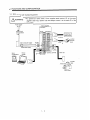
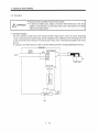
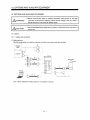
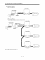
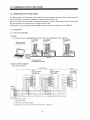
1.6 Servo System with Auxiliary Equipment
/j\WARNING
Power supply
24VDC
To prevent an electric shock, fit the suppliedearthterminal (E) to the servo
amplifier (refer to (2), Section 3.9) and alwaysconnectittotheearth
(E)of the
control box.
Servo amplifier
+I I-
To CN1A
Junction
terminal
block
To CN1B
Servo
Configuration
Personal
computer
Servo motor
1- 5
2. INSTALLATION
2. INSTALLATION
TlON
Stacking in excess of the limited numberof products is not allowed.
Install the equipment to incombustible. Installing them directly or close
to
combustibles will led to a fire.
Install the equipment in a load-bearing placein accordance with this Instruction
Manual.
Do not get on or put heavy load on the equipment
to prevent injury.
Use the equipment within the specified environmental condition range.
Provide an adequate protection to prevent screws, metallic detritus and other
conductive matter or oil and other combustible matter from entering the servo
amplifier.
Do not block the intake/exhaust ports
of the servo amplifier. Otherwise, a fault may
occur.
Do not subject the servo amplifierto drop impact or shock loads as they are
precision equipment.
Do not install or operate a fauky servo amplifier.
When the product hasbeen stored for an extendedperiod of time, consult
Mitsubishi.
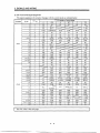
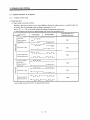
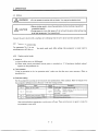
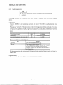
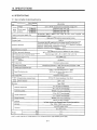
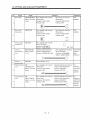
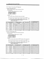
2.1 Environmental conditions
I
Environment
Ambient temperature
Ambient humihty
storage temperature
storage humidity
Ambient
Altitude
Vibration
Conditions
0 to +55 [“C] (non-freezing)
32 t o +131 [“F)(non-freezing)
90%RH or less (non-condensing)
-20 to +65 [“C] (non-freezing)
-4 to +149 [“F](nonfreezing)
90%RH or less (non-condensing)
Indoors (no dwectsunhght)
Free from corrosive gas, flammable gas,oil mist. dust anddirt
Max. lOOOm (3280 f
t
)above sea level
5.9 [m/s2](0.6G) or less
19.4 [ft/s2]or less
2-
1
1
-h
2. INSTALLATION
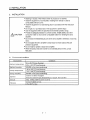
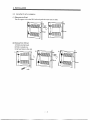
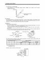
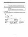
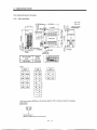
2.2 Installation direction and clearances
I
I
other
The
equipment
must
installed
be
ACAUTION
I
in the specified direction.
Otherwise,
fault
may
a
occur.
Leave specified clearancesbetween the servo amplifier and control box insidewalls
I
I
or
(1) Installation of one servo amplifier
Control box
Control box
TfP
lOmm
(0.4 in.)
or more
1Omm
-(0.4 in.)
or more
v
Bottom
(2) Installation of two or more servo amplifiers
Leave a large clearance between the top of the servo ampldier and the internal surface of the control
box, and install a fan to prevent the internal temperature
of thecontrol box from exceedmg the
environmental conditions.
10mm
-
-1 Omm
(0.4 in.)
or more
(0.4 in.)
or more
(3) Others
Install the servoamphf3er on a perpendmdar wall in the correct vertical direction.
2- 2
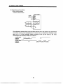
2.INSTALLATION
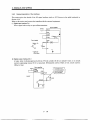
2.3 Keep out foreign materials
(1) When i n s t a l h g the unit in a control box, prevent drill chps and wire fragments from entering the
servo amphfier.
(2) Prevent oil, water, m e u c dust, etc. from entering the servo a m p a e r through openings in the control
box or a fan installed on the ceding.
(3) When i n s t a l h g the control box in a place where there are toxic gas, d x t and dust, provide positive
pressure in the control box by forcing in clean air to prevent such materials fiom entering the control
box.
2.4 Cable stress
(1) The way of clamping the cable must be f d y examined so that flexing stress and cable's own weight
stress are not appliedto the cable connection.
(2) In any application where the servo motor moves, the cables should be free from excessive stress. For
use in any application where the servo motor moves, run the cables so that their flexing portions fall
w i t h the optional motorcable range. Fix the motor cable and
power lead of the servo motor.
(3) Avoid any probabhty that thecable sheath mightbe cut by sharp chps, rubbedby a machme corner or
stamped by workers orvehicles.
(4) For installation on a machme where the servo motor will move, the 5exing radms should be made as
large as possible. Refer to section 11.4 for the 5exing Me.
2- 3
2.INSTALLATION
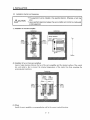
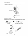
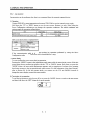
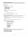
2.5 Using the DIN rail for installation
(1) Fitting intothe DIN rail
Put the upper catchon the DIN rad and push the unit until it clicks.
all
N rail
(2) Removal from DIN rail
1)Pull downthe hook.
2) Pull it towardyou.
3) Lift and remove the unit.
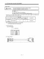
3. SIGNALS AND WIRING
3. SIGNALS AND WIRING
Any person who is involved in wiring should be fully competent to do the work.
Before starting wiring, make sure that the voltage is safe in the tester more10than
minutes after power-off. Otherwise, you may get an electric shock.
Ground the servo amplifier and the servo motor securely.
Do not attempt to wire the servo amplifier and servo motor until they have been
installed. Otherwise, you may get an electric shock.
The cables should not be damaged, stressed excessively, loaded heavily, or
pinched. Otherwise,you may get an electric shock.
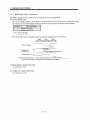
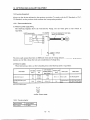
AWARNING
Wire the equipment correctly and securely. Otherwise, the servo motor may
misoperate, resulting in injury.
Connect cablesto correct terminals to prevent
a burst, fault, etc.
Ensure that polanty(+, -) is correct. Otherwise,a burst, damage, etc. may occur.
The surge absorbing diode installed to the
DC relay designed forcontrol output
should befitted in the specified direction. Otherwise, the signal is not output to
due
a fault, disabling the forced stop
and other protective circuits.
[NO
ACAUTION
ap
(24VDC)
Control output
signal
Use a noise filter,etc. to minimize the influenceof electromagnetic interference,
which may be givento electronic equipment used near the servo amplifier.
Do not installa power capacitor, surge suppressor or radio noise
filter with the power
line of the servo motor.
Do not modify the equipment.
POINT
I
CNlA and CNlB have the same shape. Wrong connection
of the connectors
wdl lead to a failure. Connect them
correctly.
3- 1
3. SIGNALS AND WIRING
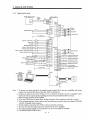
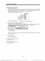
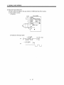
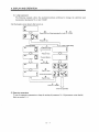
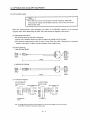
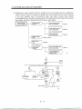
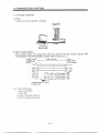
3.1 Standard connection example
I
3.1.1
For the connection of the power supply system, refer to Section 3.7.1.
Position control mode AD75PO (A1 SD75PO)
supply
power
24VDC
circuit
I
protector
amplifier
Servo
Md
lCNP1,
P24M 1
P24GI
(Nole4j
CNlE
I
I 3
4
[Note 6)
Trouble
Zero speed
Limiting toque
(Note 8) 10m (32ft)max.
',I4,7)
I
lCNlB
IEMGI 151
(Note3) Forced stop
Reset
Proportion control
Toque limit
(Note 5) Forward rotation stroke end
Reverse rotation stroke end
Upper limit sealng
(Note 8) Analog toque limit
?lOV/max. current
___--
L
I
I
K
Encoder A-phase pulse
(differential line driver)
Encoder B-phase pulse
(differential line driver)
c::2
I
Personal
'15R
I
' '
Control common
___
1
i
Encoder 2-phase pulse
[open
collector)
SD
CNP:
motor
3- 2
I
3. SIGNALS AND WIRING
Note: 1. To prevent a n electric shock, fit the supplied earth terminal (E) to the servo a m p u e r a n d always
connect it to the earth(E) of the control box. (Refer to sechon 3.9.)
2. Connect the &ode in the correct direction. If it is connected reversely, the servo ampldier w d be
faulty and wlll not output signals, h a b h g the forced stop and otherprotective circuits.
3. The forced stop switchmust be installed.
4. CNlA and CNlB have the same shape.
Wrong connection of the connectors w d lead to a fault.
signal (LSNILSP)
5. When startmg operation, always connect the forwardreverse rotation stroke end
with SG. (Normally closed contacts)
6. Trouble (AL,M) is connected with COM in normal alarm-free conhbon.
7 . The pins with the same
signal name areconnected in the servo ampkfier.
8. For the command pulse train input of the Merential h e dnver system. 2m max. for the open
collector system.
9. Use MRZJWS-SETUF'61E or later.
3- 3
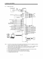
3. SIGNALS AND WIRING
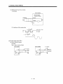
3.1.2
Speed control mode
24VDC power supply
Circuit
Servo amplifier
Speed Selection 1
(Note 3) Forced stop
Speed selection 2
Forward rotation start
Reverse rotation start
(Note 5) Forward rotation stroke end
(differential line driver)
Encoder A-phase pulse
(differential lined r i e r )
Encoder B-phase pulse
(differentlal line driver)
+10V/max. current
Encoder 2-phase pulse
Servo configuration
i
1 (Notel)
I
Note: 1. To prevent an electric shock, fit the supplied earth terminal(E) to the servo a m p a e r and always
connect it to the earth(E) of the control box. (Refer to section 3.9.)
2. Connect the diode in the correct direction. If it is connected reversely, the servo amplifier will be
faulty and wdl not output signals, &,sabhg forced
the stop and otherprotective circuits.
3. The forced stop switch mustbe installed.
4. CNlA and CNlB have the same shape.
Wrong connectionof the connectorswill lead to a fault.
5. When starting operation, always connect the forwardheverse rotation stroke end
signal (LSNLSP)
with SG. (Normally closed contacts)
6. Trouble ( A L M ) is connected with COM in normalalarm-free condtion.
7 . The pins with the same signal name are connected
in the servo ampbfier.
a. TLA can be used by setting anyof parameters No. 43 to 48 to make TL avadable.
9. Use MRZJWS-SETUP61Eor later.
3- 4
3. SIGNALS AND WIRING
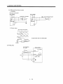
3.1.3 Torque control mode
circuit
24VDC power supply
Servo amplifier
(Note 5 )
Trouble
Speed Selection 1
Zero speed
Limiting torque
(Note 4,6)
(Note 3) Forced stop
Servo on
Reset
Speed selection2
SP2
Forward rotation selection
Reverse rotation selection
(Note 4,6)
,CNlAI
Upper limit setting
D14F)
11
Analog torque command
+BV/max. current
19
4
I~
RD
Ready
Encoder 2-phase pulse
(differential line driver)
Encoder Aphase pulse
(differential linedriver)
Analog speed limit
0 to +lOV/max. speed
Encoder B-phase pulse
(differential line driver)
Persona
1 CNP3
U
Control common
Encoder 2-phase pulse
(open collector)
T
Note: 1. To prevent an electric shock, fit the supplied earth terminal (E) to the servo amphiier and always
connect it to the earth (E) of the control box. (Refer to section 3.9.)
2. Connect the &ode in the correct duection. If it is connected reversely, the servo a m p f i e r wlu be
faulty and wdl notoutput signals,h a b h g the forced stop and otherprotective circuits.
3. The forced stop switchmust be installed.
4. CNlA and C N l B have the same shape.
Wrong connection of the connectors will lead to a fault.
5 , Trouble ( A L M ) is connected with COM in normal alarm-freecondition.
6. The pins with the same signal name are
connected in the servo amphfier.
7 . Use hfRZJW3-SETUPGlE or later.
3- 5
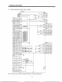
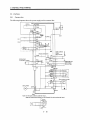
3.SIGNALS AND WIRING
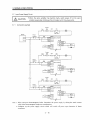
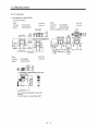
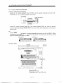
3.2 internal Connection Diagram of Servo Amplifier
CNP2
3
9-
82
B1
(Note)
I
I
I
I
Note. P: Position control mode, S: Speed control mode,T:Torque control mode
3- 6
CNlA
p
s
18
INP
SA
19
RD
RD
T
RD
3. SIGNALS AND WIRING
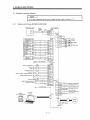
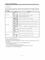
3.3 I/O Signals
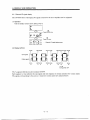
3.3.1
Connectorsand signal arrangements
POINT
I
The connector pin-outs shown above are viewed
from the cable connector
wiring section side.
&fer to the next pagefor CNlA and C N l B signal assignment.
(1) Signal arrangement
CN1B
CN1A
w
CNPl
CNP2
Amplifier's internal wiring
T h e connector frames are
connected with the E (earth)
terminal inside the servo amplifier.
E
l
1
5
I
-
I! 1 1 1I
p5
LG
I
I
CN P3
u
1
w
7
V
3- 7
I
-
3. SIGNALS AND WIRING
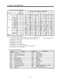
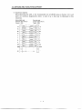
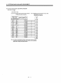
(2) CNlA and CNl B signal assignment
The signal assignmentof connector changes with the control
mode as indicated below;
page.
I
For
next
note,refer to the
3- 8
3. SIGNALS ANDWIRING
Note: 1. I : Input signal,0: Output signal, -:Others (e. g. power)
2. P : Position control mode,S: Speed control mode,T: Torque control mode, P/S: Positiodspeed control
change mode,SIT: Speedtorque control change mode,TIP: Torquelposition control changemode
3. Set parameter No. 45 to use CR.
4. Set parameter No. 47 to use PC.
5. Set parameter No. 48 to use TL.
6. By setting parameters No. 43 to 48 to make TL avdable, "L4 can be used.
7 . Set parameter No. 49 to use WNG.
8. Set parameters No. 43 to 48 to change signals.
9. Set parameter No. 49 to select alarm codes. (Refer to Chapter 9.)
1O.The signal of CNIA-18 is always output.
11.Set parameterNo. 1to select MBR.
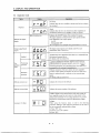
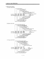
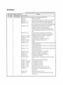
(3) Symbols and signal names
Forwardreverse rotation pulse train
3- 9
3. SIGNALS AND WIRING
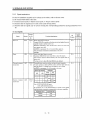
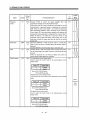
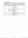
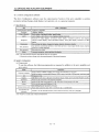
3.3.2
Signal explanations
For the I/O interfaces (symbols in 110 column in the table), refer to Section3.6.2.
In the Control Mode field of the table
P : Position control mode,S: Speed control mode,T: Torque control mode
0 : Denotes that the signalmay be used in the initial setting status.
A : Denotes that the signalmay be used by setting the corresponding parameter among parameters43 to
49.
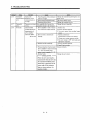
(1) Input signals
Signal
I
ZonnecSymbol tor Pin
No.
--
Functions/Applications
SON
CNlB
5
Ready signal input terminal.
Connect SON-SG to switch on the base circuit and make the servo
amplifier ready to operate (servo on).
Disconnect SON-SGto s h u t off the base circuit and coast the
servo motor(servo off).
S e t 0 0 0 1 in parameter No. 41 to switch this signal on
(keep terminals connected) automatically in the servo
teset
RES
CNlB
14
-4larm reset signal input terminal.
Disconnect RES-SG for more than 50ms to reset the alarm.
Some alarms cannot be deactivated by the reset signal. Refer ta
Sectlon 9.2.
The base circuitis shut off while RES-SG are shorted.
porward rotation
troke end
LSP
CN 1B
16
Forwardheverse rotation stroke end signal input terminals.
To start operation, short LSP-SG andior LSN-SG. Open them ta
bring the motor to a suddenstop and make it servo-locked.
S e t 0 0 0 1 in parameter No. 22 to make a slow stop.
krvo-on
(Note)
Input
signals
Lverserotation
troke end
LSN
I
~
~~
Operation
CNlB
17
Note. 0: OFF (LSPILSN-SG open)
1: ON (LSPLSN-SG shorted)
Set parameter No. 41 a s indicated below to switch on the signals
(keep terminals connected) automatically in the servo amplifier:
0100
LSN
--
3 - 10
-
Control
ie
3. SIGNALS AND WIRING
Signal
Torque limit
-
-
Symbol
IIO
Division
tor Pin
Functions/Applications
r
DI-1
TL
Short TL-SG to make the analog torque limit valid.
Forward rotation
start
ST 1
CNlB
I For details, refer to (2), section 3.3.1.
I Used to start the servo motor in anvof the following dlrections:
(Note) Input signals
ST2
I
ST1
DI-1
Servo Motor Starting Direction
I
Reverse rotation
start
ST2
1
Forward rotation
selection
RS1
Note.0: OFF (STlISTZ-SG open)
1: ON (STUSTZ-SG shorted)
If both ST1 and ST2 are switched on or off during operation. the
servomotorwillbedecelerated
to a stop according to the
parameter No. 12settingand
servo-locked.When the analog
speedcommand (VC) IS O V , startingtheservo motorwill not
generate servo lock torque.
CN 1B Used to select any of the following servo motor torque generatlor
directions:
9
Note)Inputsignals
RS2
0
Reverse rotatlon
selection
RS2
I
RS1
0
CNlB
8
0
1
1
-
1
Torque Generation
Direction
Rotation Direction
No torque
stop
Forward rotation in
driving mode / reverse
rotatlon in
regenerative mode
CCR
Reverse rotation in
driving mode /
forward rotation in
regenerative mode
No torque
Note.0: OFF (RSlRS2-SG open)
1: ON (RSlIRSZ-SG shorted)
3 - 11
DI-1
C\V
stop
-
7
Control
3. SIGNALS AND WIRING
- -
-
~~
Signal
2onnector Pin
No.
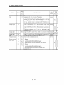
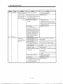
;peed selection 1
CNlA
8
ntrol
I10
3ivision
FunctiondApplications
DI-1
:Speed control mode>
Used to select the command speedfor operation.
J
(Note) Input signals
SP2
0
I
SP1
Analog speed command (VC)
0
Internal speed command 1
(parameter No. 8)
0
1
Speed Command
Internal speed command 2
O
(parameter NO. 9)
Internal speed command 3
b a r a m e t e r NO. 10)
1
Note.O:OFF (SPl/SPZ-SG open)
1:ON (SPl/SP2-SG shorted)
g o r q u e control mode>
Used to select the limit speedfor operation.
(Note) Input signals
;peed selection 2
CNlB
7
Speed Limit
SP2
SPI
0
0
Analog speed limit (VLA)
0
1
Internal speed limit 1 (parameterNo. 8)
1
0
Internal speed h i t 2 (parameter No. 9)
1
1
Internal speed limit 3 (parameter No. 10)
Note.O:OFF (SPUSPS-SG open)
l:ON (SPUSPS-SG shorted)
cpasitionispeed, speedltorque, t o r q u d p i t i o n control change mode>
4s CNlB-7 acts as a control change signal, the speed
selected when the speed or torque control mode is selected is
follows:
. When speed control mode is selected
as
i
t
(He)
SP1
Speed Command
0
Analog speed command (VC)
1
Internal speed command 1 (parameter No. 8)
Note. 0 OFF (SP1-SG open)
1: ON (SP1-SG shorkd)
. When torque control mode is selected
(Note)
SP1
n
Speed Limit
Analog speed limit (vL;\)
Internal speed limit 1 (parameter No. 8)
Note. 0:OFF (SP1-SG open)
1: ON (SP1-SGshorted)
3 - 12
I
le
3. SIGNALS AND WIRING
Signal
'orced stop
Xear
EMG
CR
LOP
~
~~
Control
I/O
Division
-
Connect
PC-SG
to switch
the
speed
amplifier
from the
DI-1
8
proportional integral type to the proportional type.
[f the servo motor a t a stop is rotated even one pulse due to any
external factor, it generates torque to compensate for a position
shift. When the servo motor shaft
is to belocked mechanically
after positioning completion (stop), switching
on the proportion
:ontrol signal (PC) upon positioning completion will suppress the
unnecessary torque generatedto compensate for a position shift.
When the shaft is to be lockedfor a long time, switch on the
(TL) at the
proportion control signal and torque control signal
same time to make the torque less than the rated by the analog
torque limit.
DI-1
CN 1B DisconnectEMG-SG to bring the servo motor to a forced stop
jtate, in which the servo is switched off and the dynamic brake is
15
Dperated.
Connect EMG-SG in the forced stop state to reset that state.
CNlA Connect CR-SG to clear the position control counter droop pulses DI-1
3n the leading edge of the signal. The pulse width shouldbe lOms
8
Dr more.
When theparameter No. 42 settingis 0010, thepulsesare
always cleared while CR-SGare connected.
CN 1B <Positiodspeed control change mode>
DI-1
Used to selectthecontrolmodeinthepositiodspeedcontrol
7
change mode.
CN 1B
hntrol change
Functions/Applications
-
'roportion
ontrol
-
~~
Connector Pin
No.
€€I
(Note) LOP
Control Mode
Position
Speed
Note.0: OFF (LOP-SG open)
1: ON (LOP-SG shorted)
<Speed/torque control change mode>
Used to select the control mode in the speeatorque control change
mode.
Refer to
Functions
Appll.
cations
Note.0: OFF (LOP-SG open)
1: ON (LOP-SG shorted)
<Torque/position control mode>
Used to selectthecontrolmodeinthetorquelpositioncontrol
change mode.
Position
Note.0: OFF (LOP-SG open)
1: ON (LOP-SG shorted)
3 - 13
-
3. SIGNALS AND WIRING
-Signal
3ymbol
2onnec
tor Pin
--
lFunctions/Applications
No.
TL4
CNlB
12
-4nalog torque
command
Analog speed
command
Analog speed
limit
Forward rotation
pulse train
Reverse rotation
pulse train
CNlB
2
CNlA
3
CN 1.4
2
CN 1.4
13
CN 1 4
12
-
To use thissignal
in thespeedcontrolmode,setany
of
parameters No. 43 to 48 to make TL available.
When the analog torque limlt (TU)is valid, torque is llmlted In
the fullservomotoroutputtorquerange.
Apply 0 to +IO 6DC
across TLA-LG. Connect the positive terminal of the power supply
to TL4. Maximum torque is generated at +10 V. (Refer to (2) in
Section 3.4.1.)
Usedtocontroltorque
in the full servo motor outputtorque
range.
Apply 0 to k8VDC across TC-LG. Maximum torque is generateda t
k8V. (Refer to (1) in Section 3.4.3.)
Thetorquegeneratedat
k8V inputcan
be changedusing
parameter No. 26.
Apply 0 to k1OVDC across VC-LG. Speed set in parameterNo. 25
IS provided a t klOV. (Refer to (1) in Section 3.4.2.)
Apply 0 to k1OVDC across \ZA-LG. Speed set in parameter No.
25 is provided a t -LlOV. (Refer to (3) in Section 3.4.3.)
Used to enter a command pulse train.
. In the open collector system (max. input frequency
200kpps):
Forward rotation pulse train across PP-SG
Reverse rotation pulse train across NP-SG
. In the differential receiver system (max. input frequency
500kpps):
Forward rotation pulse train across PG-PP
Reverse rotatlon pulse train across NG-NP
The command pulse tramform can be changed using
parameter No. 21.
3 - 14
I
Control
3.SIGNALS AND WIRING
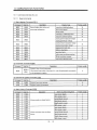
(2)Output signals
ConnecSignal
l'rouble
I
ALM
I
I
CNlB
/ 1 8
Ready
18
77
Speed reached
Limiting
speed
VLC
1B
CN
6
Limiting
torque
TLC
CNlB
6
Zero speed
Electromagnetx
x a k e Interlock
ZSP
CNlB
19
T
I
I
FunctionsiApplications
Control
I k
Division
'I0
ALM-SG aredisconnectedwhenpower
is switched off or the DO-1
protective circuit is activated to shutoff the base circuit. Without
alarm, .4LM-SG are connected within 1 after power on.
RD-SG are connected when the servo is switched on and the servoDO-1
amplifier is ready to operate.
INP-SG are connected when the number of droop pulses is in the DO-1
presetin-positionrange.TheIn-positionrangecan
be changed
using parameter No. 5 .
be kept
When thein-positionrange is Increased,INP-SGmay
connected during low-speed rotation.
SA-SG areconnectedwhentheservomotorspeedhasnearly
DO-1
reached the preset speed. When the preset speed is 50r/min
or
less, SA-SGare kept connected.
LZC-SG are connected when speed reaches the value set to anyof DO-1
the internal speed limits 1 to 3 (parameters No. 8 to 10) or the
analog speed limit &%A) In the torque control mode. They are
disconnected when the servo-on signal(SON)switches off.
DO-1
TLC-SG are connectedwhenthetorquegeneratedreachesthe
value settotheInternaltorquelimit
1 (parameter No. 28) or
analog torque limit (TUThey
). are disconnected when the servoon signal (SON)switches off.
DO-1
ZSP-SG are connected when the servo motor speed is zero speed
(50rimin) or less. Zero speed canbe changed using parameter No.
24.
S e t 0 0 1 0 in parameter No. 1 touse thls parameter. Note that DO-1
ZSP will be unusable.
In the servo-off or alarm status. MBR-SG are dlsconnected.
When an alarm occurs, they are
dlsconnectedindependently of
the base circuit status.
use thisslgnal,assigntheconnector
pin foroutputusing
DO-1To
will be
parameter No. 49. The old slgnalbeforeassignment
unusable.
When warning has occurred,\VNG-SG are connected.
When there is no warning, WNG-SG are disconnectedwithin 1
second after power-on.
3 - 15
0
0
0
0
C
A
A
J
3. SIGNALS AND WIRING
-
T
Connec-
Symbol
tor Pin
I/o
Division
FunctiondApplications
No.
darm code
CN 1A
19
CNlA
18
CN 1B
19
To use this signal, set 0 0 0 1 in parameter No. 49.
This signal is output when an alarmoccurs. When there is nc
INP, SA ZSP) are output.
alarm, respective ordinary signals0,
Alarm codes and alarm names are listedbelow:
(Note) Alam
GqGii
A'arm
I9 Pin
lgy,l
0
4
1
Display
1
1
Note. 0: OFF (Pin-SG open)
1: ON (Pin-SG shorted)
3 - 16
I
Name
I
DO-1
Control
3. SIGNALS AND WIRING
-
T
hnnector Pin
No.
Signal
Encoder Z-phase
OP
PUh
(Open collector)
Encoder B-phase
PUk
(Differential line
driver)
Encoder Z-phase
PUl=
(Differential line
driver)
CN 1A
14
Outputs the zero-point signal of the encoder. One pulse is output
per servo motor revolution. OP and LG are connected when the
zero-point position is reached. (Negative logic)
The maximum pulse width is about 4OOp. For zeroing using this
pulse, set the creep speedto 100r/min. or less.
Outputs pulses per servo motor revolution set in parameter No.
27 in the differential line driver system. The encoderB-phase
pulse lags the encoder A-phase pulseby a phase angleof d 2 .
CN 1A
Encoder A-phase
PUh
(Differential line
driver)
6
LAR
CN 1A
16
LB
CNlA
LBR
7
CN 1A
17
CN 1A
-The same signal aa OP is output in the diEferential line driver
5
system.
CNlA
15
-
3 - 17
3. SIGNALS AND WIRING
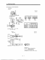
(3) Power supply
Signal
[iF internal
3ower supply
Digital I F power
supply input
-Symbo
\-DD
COM
)pen collector
lower input
Iigital I F
:ommon
OPC
ICl5V power
Pl5R
SG
,UPPlY
2ontrol common
Connec
tor Pin
No.
LG
CNlB
3
CNlA
9
CNlB
13
CN 1.4
11
CNlA
10
20
CNlB
10
20
CNlA
4
CN 1B
11
CNlA
1
CNlB
I
Functions/Applications
I/O
Division
Control
F
Used to output 24IDC for input interface.
Connected with P24L inside the servo amplifier.
Used to input 24VDC for input interface.
Connect the positive terminal of the 24VDC external power
supply.
24TrDCkIO%
When inputting a pulse train in theopen collector system, supply
this terminal with the positive (+) power of 24VDC.
Common termmal for Input slgnals such asSON and EMG. Pins
are connected internally.
Internally connected with LG.
Outputs 15VDC to across Pl5R-LG. Availablea s power for TC,
TL4,VC, \'LA.
Permissible current: 30mA
Common termmal for TLA,TC, I'C, \X\, FP.4, FPB. OP and
P15R.
Plns are connected internally.
1
CN3
1
0
3
5
lhield
11
13
15
Plate
-SD
h n e c t the external conductorof the shield cable.
\O
3. SIGNALS AND WIRING
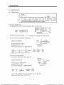
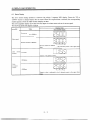
3.4 Detailed Description of the Signals
3.4.1
Position control mode
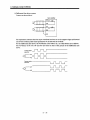
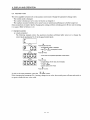
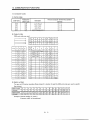
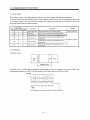
(1) Pulse train input
(a) Input pulse waveform selection
Encoder pulses maybe input in anyof three dlfferent forms,for w h c h positive or negative logic can
be chosen. Set the command pulse train
form in parameter No. 21.
Arrow flor in the table inhcates the timing
of importing a pulse train.
A- and B-phase pulse trains are imported
after they have been multipliedby 4.
Pulse Train Form
Forward rotatlon
?ulse train
Reverse rotation
pp
(Note) Parameter No. 21
(Command pulse train)
Reverse Rotation
Forward Rotation
Q
0010
N
pulse train
P
U
U
U
U
Pulse train + sign
0011
NP
A-phase pulse train
B-phase pulse train
-
I
Forward rotation
pulse train
Reverse rotation
H
I
N
I
P
P
0012
PP _flflflfl
NP
pulse train
PP
Pulse train + sign
NP
A-phase pulse t r a m
B-phase pulse train
L
1
NP
0000
flflflfl
H
I
L
Note: Set "OOOO when using theAD75P in the programmable controller.
3 - 19
000 1
I
0002
3. SIGNALS AND WIRING
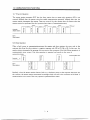
(b) Connections and waveforms
1) Open collector system
Connect as shownbelow:
Servo amdier
OPC
+
I
The explanation assumes that the input waveform has been set to the negative logic and forward
and reverse rotation pulse trains (parameter No.21 has been set to 0010). The waveforms in the
table in (a), (1) of this section are voltage waveforms of PP and NP based on SG. Their
relationships with transistorON/OFF are as follows:
Forward rotation
pulse train
(transistor)
Reverse rotation
pulse train
(transistor)
(OFF)
(OFF)
3. SIGNALS AND WIRING
2) Differential h e driver system
Connect as shown below:
Servo amplifier
YSD
The explanation assumesthat the inputwaveform has been set to the negative logic and forward
and reverse rotation pulsetrains (parameter No.21 has been set to 0010).
For the differential line driver, the waveforms
in the table in (a), (1)of this section are as follows.
The waveforms of PP, PG, NP and NG are based on that of the ground of the differential line
dnver.
3 - 21
3. SIGNALS AND WIRING
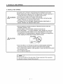
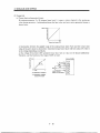
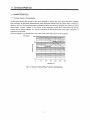
(2) Torque limit
(a) Torque limit and generated torque
By setting parameter No. 28 (internal torque limit 1). torque is always limited to the maximum
value during operation.A relationshp between the h i t value and servo motor-generated torque is
shown below.
Torque limit value
[%I
A relationshp between the applied voltage of the analog torque h i t (TU)and the torque limit
value of the servo motor is shown below. Generated torque h i t values wdl vary about 5% relative
to the voltage d e p e n h g on products.
At the voltage of less than O.O5V, generated torque may vary as it may not be h i t e d sufficiently.
Therefore, use thisfunction at thevoltage of 0.05V or more.
Servo amplifier
=
&
a
Jp
RRS10
:
or equivalent
3 - 22
3. SIGNALS AND WIRING
(b) Torque limit value selection
Choose the torque h i t made valid by the internal torqueh i t value 1 (parameter No. 28) using the
external torque limit selection (TL) or the torque h i t made vahd by the analog torque h i t (TU)
as indicated below:
Torque LimitValue Made Valid
(Note) TL
If TLA > Parameter No. 28
If TLA < Parameter No. 28
Internal torque limit value 1
(parameter No. 28)
Internal torque limit value 1
Analog torque limit (TU)
(parameter No. 28)
0
1
Note. 0 : TU-SGoff (open)
1 : TLA-SG on (short)
(c) h i t i n g torque (TLC)
TLC-SG are connected when the torque generated by the servo motor reaches the torque set
internal torque h i t value 1or analog torque limit.
to
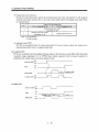
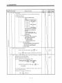
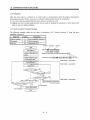
(3)In-position (INP)
PF-SG are connected when the numberof droop pulses in the deviation counter falls w i t h the preset
in-position range(parameter No. 5). INP-SG mayremainconnectedwhenlow-speedoperationis
performed with a large value set
as the in-position range.
Servo-on (SON)
Alarm
ON
OFF
Yes
No
Droop pulses
ON
In position (INP)
OFF
(4) Ready (RD)
Servo-on (SON)
Alarm
OFF
Yes
No
80ks or les-
Ready (RD)
OFF
3 - 23
or less
3. SIGNALS AND WIRING
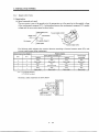
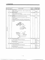
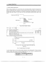
3.4.2Speed
control mode
(1) Speed setting
(a) Speed command and speed
The servo motoris run at the speeds set in the parameters
or at thespeed set in theapplied voltage
of the analog speed command(VC). A relationshp between the analog speed command
(VC) applied
voltage and the servomotor speed is shown below:
Rated
[r'minl
~
Forward
rotation
(CCW)
CCW direction
-1 0
CW direction 1
VC applied
voltage
[VI
.__._-
I
Rated speed
.\ Reverse rotation (CW)
The following table in&cates the rotation dnection accordmg to forward rotation s t a r t (ST1) and
reverse rotation start (ST2) combination:
Rotation Direction
Analog Speed Command (VC)
(Note) External Input Signals
ST2
ST 1
0
0
0
1
1
0
1
1
+ Polarity
ov
stop
(Servo lock)
CCN'
CW
stop
(Servo lock)
stop
- Polarity
stop
(No servo lock)
stop
(Servo lock)
Stop
stop
(Servo lock) (Servo lock) (Servo lock)
CW
ccw
CCR'
CW
stop
(Servo lock)
Note. 0 : STlIST2-SG off (open)
1 : STlIST2-SG on (short)
Generally, makeconnection as shown below:
Servo amolifier
I
JapanResistor
---RRS10 or equivalent
3 - 24
lntemal Speed
Commands
stop
(Servo lock)
3. SIGNALS AND WIRING
(b) Speed selection 1 (SPl), speed selection2 (SP2) and speed command value
Choose any of the speed settings made by the internal speed commands1to 3 using speed selection
1(SP1) and speed selection 2 (SP2) or the speed setting made
by the analog speed command(VC).
~~
(Note) External Input Signals
SP2
I
0
0
0
1
1
Speed Command Value
SP1
1
0
1
Analog speed command (VC)
Internal speed command 1 (parameter No. 8)
Internal speed command 2 (parameter No. 9)
Internal speed command 3 (parameter No. IO)
Note. 0 : SPl/SPB-SG off (open)
1 : SPl/SPS-SG on (short)
The speed may be changed during rotation. Inths case, the values set in parameters
No. 11 and 12
are used for acceleratioddeceleration.
When the speed hasbeen s p e c ~ e dunder any internalspeed command, it does not vary due to the
ambient temperature.
(2)Speed reached (SA)
SA-SG are connected when the servo motor speed nearly reaches the speed set
command or analog speed command.
Internal speed
command 1
Set speed selection
Start (ST1,ST2)
gpF
1
Internal speed
command 2
I
t
Servo motor speed
Speed reached (SA)
ON
(3)Torque limit
As in Section 3.4.1(2).
3 - 25
I
,
,
I
I
,
to the internal speed
3.SIGNALS AND WIRING
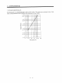
3.4.3 Torque control mode
(1) Torque control
(a) Torque command and generated torque
A relationship between the applied voltage
of the analog torque command (TC) and the torque
generated by the servo motor is shown below.
The maximum torque is generated at +8V. Note that the torque generated at f8V input can be
changed with parameter No. 26.
h
CCW direction
Generated torque
d.05 +8
TC applied voltage [VI
Max. torque (Note)
CW direction
Generated torqueh i t values will vary about 5% relative to the voltage d e p e n h g on products.
Generated torque may vary at thevoltage of -0.05V to +0.05V.
The following table indicates the torque generation drections determined by the forward rotation
selection (RS1) and reverse rotation selection ( R S 2 ) when the analog torque commandP C ) is used.
I (Note) External Input Signals I
RS2
RS1
+ Polarity
I
1
Rotation Direction
Torque control Cornrn md ( X )
I
I
I
1
ov
No torque
CCW (reverse rotation in
driving mode/forward
rotation in regenerative
mode)
CW (forward rotation in
driving modelreverse
rotation in regenerative
mode)
No toraue
No torque
Note. 0: RSl/RSP-SG
off (open)
1: RSIR.52-SG on (short)
Generally, make connection as shown
below:
Servo amlifier
3 - 26
- Polarity
No torque
CM' (forward rotation in
driving mode/reverse
rotation in regenerative
mode)
CCW (reverse rotation in
driving mode/forward
rotation in regenerative
3. SIGNALS AND WIRING
(b) Analog torque command offset
Using parameter No. 30, the offset voltage of -999 to +999mV can be added to the TC applied
voltage as shown below.
Max.
//
:I
P
c
Parameter No.30offset range
I -999 to +999mV
'1
+8 (-8)
TC applied voltage [VI
(2) Torque limit
By setting parameter No. 28 (internal torque h i t l),torque is always lunited to the maximum value
during operation. A relationshp between h i t value and servo motor-generated torque is as in (2) in
section 3.4.1. Note that the analog torqueh i t (TU)is unavdable.
(3) Speed limit
(a) Speed limit value and speed
The speed is lunited to the values setin parameters No. 8 to 10 (internal speed h i t s 1 to 3) or the
value set in the applied voltage
of the analog speed limit(VLA).
A relationship between the analog speed h i t (VLA) applied voltage and the servo motor speed is
shown below.
When the motor speed reaches the speed
h i t value, torque control maybecome unstable. Make the
set value more than 100r/m smaller than the desired speed limit value.
Rated speed
~
CW
direction
I
Forward rotation (CCW
CCW direction
VLA
applied
voltage
[Vj
Rated speed
___._-
1
"\ Reverse rotation (CW)
Thefollowingtable
indicatesthelimitdirectionaccordingtoforwardrotation
reverse rotation selection (RS2) combination:
(Note) External Input Signals Speed
RS1
RS2
1
0
0
1
Limit Direction
Analog Speed Limit ( V U )
+ Polarity
- Polarity
ccw
CW
CW
Note.0: RSlRS2-SGoff (open)
1: RSlIRS2-SG on (short)
Generally, make connection as shownbelow:
Servo arndifier
I
~
SP2
:I::$
vc
2w2
JapanResistor
---RRSlO or equivalent
3 - 27
LG
SD
selection (RSl) and
Internal Speed
Commands
CCR'
CR' CCR'
3. SIGNALS AND WIRING
(b) Speed selection 1 (SPl)/speed selection 2 (SP2) and speed command values
Choose any of the speed settings made by the internal speed h i t s 1 to 3 using speed selection 1
(SP1) and speed selection2 (SP2) or the speed setting madeby the speed limit command(VLA).
(Note) External Input Signals
I
1
0
1
1
Speed Command Value
I
Speed limit command &%A)
Parameter No. 8
Parameter No. 9
Parameter NO. 10
I
Note.0: SPlISP2-SGoff (open)
1: SPUSPS-SG on (short)
When the internal speed commands 1 to 3 are used tocommand the speed, the speed does notvary
with the ambient temperature.
(c) b i t i n g speed (VLC)
TLC-SG are connected when the
servo motor speed reaches theh i t speed set to any of the internal
speed h i t s 1to 3 or analog speed h i t .
3. SIGNALS AND WIRING
3.4.4
Position/speed control change mode
Set 0001 in parameter No. 0 to switch to the positiodspeed control change mode. Ths function is not
avadable in the absolute position detectionsystem.
(1) Control change (LOP)
Use control change(LOP) to switch between theposition control mode and the speedcontrol mode from
an external contact. Relationshps between
LOP-SG status and control modes are inhcatedbelow:
(Note) LOP
0
1
Servo Control Mode
Position control mode
Speed control mode
Note. 0: LOP-SGoff (open)
1: LOP-SG on (short)
The control mode may be changed in the zero-speed status.To ensure safety, change control after the
servo motor has stopped. When position control mode is changed to speed control mode, droop pulses
are reset.
If the signal has been switched on-off at the speed hgher than the zero speed and the speed is then
reduced to the zero speed or less, the control mode cannot be changed. A change timing chart is shown
below:
Position
Position
SPd
control mode , control mode , control mode
Zero speed (ZSP)
ON
OFF
ON
Control change (LOP)
(Note)
OFF
,_.-
I
(Note) I
I_._
Note: WhenZSP is not on, control cannotbe changed if LOP is switched on-off.
If ZSP switcheson after that, control cannot
not be changed.
(2) Torque limit in position control mode
As in Section 3.4.1 (2).
3 - 29
3. SIGNALS AND WIRING
(3)Speed setting in speed control mode
(a) Speed commandand speed
The servo motor is run at the speed set in parameter No. 8 (internal speed command 1) or at the
speed set in the applied voltage of the analog speed command (VC). A relationshp between analog
speed command (VC) applied voltage and servo motor speed and the rotation duections determined
by the forward rotation start signal (ST1) and reverse rotation start signal(ST2) are as in (a), (1) in
section 3.4.2.
Generally, make connection as shown below:
_____
2kQ
Servo amplifier
-
-
----<
SD
Japan
Resistor
RRS10 or equivalent
, ,
When a precision speed command is required, referto (a), (1)in section 3.4.2
(b)
Speed selection 1 (SP1) and speed command value
Use speed selection 1 (SP1) to select between the speed set by the internal speed command 1 and
the speed setby the analog speed command(VC) as inhcatedin the following table:
(Note) External Input Signals
SPI
0
1
Speed Command Value
I Analog
speed
command
I Internal
speed
command
PTC)
1 (parameter No. 8)
h’ote. 0: SP1-SG off (open)
1: SP1-SG on (short)
The speed may also be changed during rotation. In t h s case, it is increased or decreased accordmg
to the value set in parameterNo. 11or 12.
When the internal speed command 1 is used to command the speed, the speed does not vary with
the ambient temperature.
(c) Speed reached (SA)
As in Section 3.4.2 (2).
3 - 30
3. SIGNALS AND WIRING
3.4.5 Speedhorque control change mode
Set 0003 in parameterXo. 0 to switch to the speedtorquecontrol change mode.
(1) Control change (LOP)
Use control change (LOP) to switch between the speed controlmode and the torque control mode from
an externalcontact. Relationshps betweenLOP-SG status andcontrol modes are indicated below:
Note. 0:LOP-SG off (open)
1: LOP-SG on (short)
The control mode may be changed a t any time.A change timing chartis shown below:
TorqueSpeed
speed
control mode, control mode, control mode
Servo motor speed
Analog torque
command (TC)
Control
change
1ov
0
(Lop) oN
OFF
r ' i
Note: When the start signal (ST1. ST2) is switched off as soon as the mode is changed tospeed control,
the servo motor comes to a stop according
to the decelerationtime constant.
(2) Speed setting in speed control mode
As in Section 3.4.2 (1).
(3) Torque limit in speed control mode
As in Section 3.4.1 (2).
3 - 31
3. SIGNALS AND WIRING
~
(4) Speed limitin torque control mode
(a) Speed lunit value and speed
The speed is limited to the h i t value set in parameterNo. 8 (internal speed limit1)or the value set
in the applied voltageof the analog speedh i t (VLA). A relationshp between the analog speed
hit
(VLA) applied voltage and the servo
motor speed is as in (a),(3) in section 3.4.3.
Generally, make connectionas shown below:
Servoamplifier
.____
Japan Resistor
RRSlO or equivalent
When a precision speed commandis required, refer to (a), (3) in section 3.4.3.
@I) Speed selection 1 (SP1) and speed limit value
Use speed selection 1 (SP1) to select between the speed set by the internal speed command 1 and
the meed setby the analog speedb i t (VLA) as indicated in thefollowing table:
(Note) ExternalInput Signals
Speed Command Value
ED1
I Analog speed limit (VIA)
I Internal speed limit 1 (parameter No. 8)
0
1
Note.0: SP1-SGoff (open)
1: SP1-SGon (short)
When the internal speed lunit 1 is used to command the speed, the speed does not vary with the
ambient temperature.
(c) Limiting speed (VLC)
As in (c), (3) in section 3.4.3.
(5) Toque control in torque control mode
As in Section 3.4.3 (1).
(6) Torque limit in torque control mode
As in Section 3.4.3 (2).
3 - 32
.
-
._.
3. SIGNALS AND WIRING
3.4.6
Torque/position control change mode
Set 0005 in parameter No. 0 to switch to the torque/position control change mode.
(1) Control change(LOP)
Use control change (LOP) to switch between the torque control mode and the position control mode
below:
from a n external contact. Relationships betweenLOP-SG status and control modes are indxated
h
Servo Control Mode
Torque control mode
Position control mode
Note. 0: LOP-SG off (open)
1: LOP-SG on (short)
The control mode maybe changed in the zero-speed status.
To ensure safety, change control after the servo motor has stopped. When position control mode is
changed to torque control mode, drooppulses are reset.
If the signal has been switched on-off at the speed higher than the zero speed and the speed is then
reduced to the zero speed or less, the control mode cannot be changed.A change timing chartis shown
below:
Analog torque
command VIA)
Zero speed (ZSP)
1ov
ov
ON
OFF
1
-
Control change (Lop) oN
OFF
(2) Speed limitin torque controlmode
As in Section 3.4.3 (3).
(3) Torque controlin toque control mode
As in Section 3.4.3 (1).
(4) Torque limit in torque control mode
As in Section 3.4.3 (2).
(5) Torque limit in position controlmode
As in Section 3.4.1 (2).
3 - 33
1
-
3. SIGNALS AND WIRING
3.5 Alarm Occurrence Timing Chart
When an alarm hasoccurred,removeitscause,
make sure thattheoperation
signal is not
being
input,
ensure
safety,
and
reset
the
alarm
before
restarting
operation.
&AUTION
When an alarm occurs in the servo ampMer, the
base circuit is shut off and the servo motoris coated to a
stop. Switch off the main circuit power supply in the external sequence. To reset the alarm, switch the
control circuit power supplyoff, then on.
However, the alarm cannotbe reset unless its cause of occurrence is removed.
power
supply
ON
OFF
I
lPower
Off
t Power on
I
Base circuit
Dynamic brake
more
Remove cause of trouble.
Precautions for alarm occurrence
1) Overcurrent, overload 1or overload 2
If operation is repeated by switchmg control circuitpower off, then onto reset the overcurrent(A.
32), overload 1 (A. 50) or overload 2 (A. 51) alarm after its occurrence, without removingits cause,
the servo amphfier and servo motor may
become faulty due to temperature rise. Securely remove
the cause of the alarm andalso allow about 15 minutesfor c o o h g before resuming operation.
2) Instantaneous power failure
If a power fadure continues 15ms or longer, the undervoltage (A. 10) alarm will occur. If the
power fadure stdl persistsfor 20ms or longer, the control circuit is switched off. When the power
failure is reset in t h s state, the alarm is reset and the servo motor wlll start suddenly if the
servo-on signal (SON) is on. To prevent hazard, make up a sequence which wdl switch off the
servo-on signal(SON) if an alarmoccurs.
3) Position control mode
When an alarmoccurs, the home position is lost. When resuming operationafter deactivating the
alarm, make a returnto home position.
3 - 34
3. SIGNALS AND WIRING
3.6 Interfaces
3.6.1
Common line
The following b a g r a m shows the power supply andits common line.
CNPl 1
I
i
DO-1
SON etc.
ALM etc.
Open collector
output
I
L
Servo motor
CNP2
3 - 35
output
Differential line
driver
3. SIGNALS AND WIRING
3.6.2
Detailed description of the interfaces
This section gives the details of the I/O signal interfaces (refer to I/O Division in the table) indxated in
Section 3.3.2.
Refer to t h s section and connect the interfaces with the external equipment.
(1) Digital input interface Dl-1
Give a signal with a relayor open collectortransistor.
Servo amplifier
24VDC
For a transistor
I
I
Approx. 5mA
r
V CESS1.OV
I CECKlOOfl
(2) Digital output interface DO-1
A lamp, relay or photocoupler can be driven. Provide a &ode (D) for a n inductive load, or an inrush
current suppressing resister (R) for a lamp load. (Permissible current: 4omA or less, inrush current:
l O O m A or less)
Servo amplifier
connected as shown,
the sew0 amplifier
3 - 36
3. SIGNALS AND WIRING
(3) Pulse train input interfaceDl-2
Provide a pulse train signal in the open collector or Merential h e dnver system.
(a) Open collector system
1)Interface
24VDC
Servo amplifier
!.P24G
Y
2) Conditions of the input pulse
3 - 37
3. SIGNALS AND WIRING
(b) Dlfferential line driver system
1) Interface
Servo amplifier
Max.input pulse
frequency 500kpps
Y
SD
2) Conhtions of the input pulse
J
,
tC
tLH = tHL c 0.luS
(4) Encoder pulse output DO-2
(a) Open collector system
Interface
Max. output current 35mA
Servo
amplifier
Servo amplifier
m
5 to 24VDC
I
I
'
,. _ _
I !
LG
S D'
3 - 38
Photocoupler
3. SIGNALS AND WIRING
@) Ddferential h e dnver system
1)Interface
Maxoutput current 35mA
Servo amplifier
Servo amplifier
I
LA
(LB,LZ)
Am26LS32 or equivalent
I
(LBRUR)
+
1-/---I
I
,
,
I
.
I
8
,
1
I _ _ _ .
{
-
1OOR High-speed
photocoupler
U
/
1
/
..PI----
2) Output pulse
Servo motor CCW rotation
LA-Lju-u-
LBE
LAR
LBR@&
LZ signal varies k3BT on its leading edge
L
z
LZR
open
op
Shorted
u L 4 ~ more
p ors
v
(5)Analog input
Input impedance
10 to 1 2 m
Servo amplifier
I
3 - 39
3. SIGNALS AND WIRING
3.7
Input Power Supply Circuit
A
3.7.1
~ ~ ~ _ _ _ _ _
~~
CAUTION
~~
~~~~~~~
When the servo amplifierhas become faulty,switchpower
off on the servo
amplifier power side. Continuousflow of a large current may causea fire.
Connection example
Forced
Stop
RA1
OFF
ON
G
Circuit
CNlB
3 VDD
13
COM
18
ALM
Forced
RA3
OFF
Stop
ON
Y
I
P24L
3
1 SG 1
10
I
Forced
protector
RA6
ENPl
P24M
1
P24G
2
Servo
ampllfler
CNlB
CN1B
EMG
15
SG
10
&
Y
--
Note: 1.When using an electromagnetic brake. determine the power supply
by taking the rated current
value of the electromagnetic brake into consideration
2. Configureup the power supplycircuitwhich
will switch off power upondetection of alarm
occurrence.
3 - 40
3. SIGNALS AND WIRING
3.7.2
Explanation of signals
Abbreviation
Signal Name
Description
P24M
Main circuit power input
P24G
Power ground
P24L
Control power input
_L
-
Ground
Power supply for main circuit
Main circuit power supply and control power supply. Connected to SG and LG
inside the unit.
Control power supply and digital 1/0 power supply. Always
use a stabilizing
power supply.
Grounding terminal
Connect to the earthof the control box for grounding.
-
3.7.3
Power-on sequence
(1) Power-on procedure
1) Always wire the power supply
as shown in above Section 3.7.1 using the relay with the main
circuit power supply. Configure up an external sequence to switch off the relay as soon as an
alarm occurs.
2) Switch on the control circuit power supply P24L, P24G simultaneously with the main circuit
power supply or before switching on the main circuit power supply. If the main circuit power
supply is not on, the &splay shows the corresponding warning.
However, by switchng on the
main circuit power supply, the warning &sappears and the servo
amplifier w d operate properly.
3) The servo ampuler can accept the servo-on signal (SON) about 1 second after the main circuit
power supply is switched on. Therefore, when SON is switched on simultaneously with the 24V
power supply, the base circuit w d switch on in about 1 second. and the ready signal (RD) wdl
switch on in further about 20ms, malung the servo
ampM1er ready to operate.
(2) Timing chart
SON accepted
1
N
Powersupply
ON
OFF
Base
circuit
ON
OFF
Servo on
f
,
I
(1s)
1'
,
I
I
,
lOms,
~
I
ON
3 - 41
-
,
# _ 6 0 m s _
4
1
3. SIGNALS AND WIRING
(3) Forced stop
A
CAUTION
To stop operation and switch power off immediately, provide a forced stop circuit.
Make up a circuit whch shutsoff main circuit power as soon as EMG-SG are opened at a forced stop.
To ensure safety, always install a forced stop switch across EMG-SG. By &sconnecting EMG-SG, the
dynamic brake is operated to bring the servo
motor to a suddenstop. At ths time, the &splay shows the
servo forced stop warning (A. E6).
During ordmary operation,do not use the forced stop signal to alternate stop and run.
If the start signal is on
or a pulse train is input during aforced stop, the servo motor wdl rotate as soon
as the warning is reset. Duringforced
a
stop, always shutoff the runcommand.
Servo amplifier
(4) CNP1 connector wiring
The servo amphfier is packed with the
following parts for wiring the CNP1.
For connection of the terminals and cables, use the crimping tool 57026-5000 (for UL1007) or 570275000 (for UL1015).
Part
Model
Maker
Connector
Terminal
5557-08R
5556
molex
3 - 42
3.SIGNALS AND WIRING
3.8 Servo Motor with Electromagnetic Brake
(1) Setting
Using parameter No.33 (electromagnetic brake sequence output), set a time delay from electromagnetic
shown in (2) in this section.
brake operation to base circuit shut-off as in the timing chart
(2) Operation timing
(a) Servo on signal command (from controller) ON/OFF
Tb after the servo-on signal is switched
off, the base circuit is shut
off and the servo motor coasts.
The following chart shows theway of holdmg the motor shaft in verticallift applications.
*
Adjust Tb (parameter No. 33) to minimize a drop after the servo-on signal is switched
off.
Switch off the servo-on signal after the servo motor has stopped.
-
[,T
Coasting
Servo motor
speed
0 r'min
Base circuit
Electromagnetic
brake (CNP2-9)
Servo-on(S0N)
(b) Emergency stop signal (EMG) ON/OFF
Dynamic brake
Electromagnetic brake
release
brakeElectromagnetic
Servo motor speed
I
I
,
Base circuit
I
I
- _ - - _ _ ---
I
Electromagnetic
Invalid(ON)
brake(CNP2-9)
iilectromagnetic brak++
;operation
delay
lime ;
(10ms)
Forced stop(EMG)
180ms)
__----_--
-----------
3 - 43
3. SIGNALS AND WIRING
(c) Alarm occurrence
Dynamic brake
- y l & r o m a g Dynamic
n e t i c brake brake
Servo motor speed
------- ---I
I
Base circuit
ON
-_---
1-
OFF
Electromagnetic
Invalid(oN)
brake(CNP2-9)
Valid(OFF)
.- - -
-
'
Electromagnetic brake
operation delay time(l0ms)
Y
No(0N)
Trouble (ALM)
Electromagneticbrake
,
,
--- ---
Yes(0FF)
(d) Main circuit power
off
When main circuitpowerswitches off, the undervoltage alarm
timing is as shown in (c) of this section.
(A.10) occurs and the operation
(e) Control circuit poweroff
-1-
Servo motor speed
Control power
(P24L)
Coasting
++ ,-lOms
Electromagneticbrake
ON
OFF
(3)Release of electromagnetic brake
To release the electromagnetic brake when main circuit power is
off, use the output signal
forced
output (referto Section 6.7).
The electromagnetic brake can be released by turning on the electromagnetic brake power B l (CNPZ9).
3 - 44
3. SIGNALS AND WIRING
3.9 Grounding
~~~~~
A
WARN'NG
~
~
~~
~
~
~
Ground the amplifier
servo
motor
servo
securely.
and
To prevent an electric shock, always connect the earth terminal (E) of the servo
amplifier to the earth (E) of the control box (refer to (2) of this section for the fitting
method of the earthterminal).
I
(1) Connection diagram
The servo ampM1er switches thepower transistor on-off to supply power tothe servo motor. Depending
on the wiring and ground cablerouting, the servo amphfier may beaffected by the switchmg noise (due
to dddt and dv/dt)of the transistor. To prevent such a fault, refer to the following diagram and always
ground.
To conform to the EMC Directive, refer to theEMC INSTALLATION GUIDELINES (TB(NA)67310).
Control box
I
I -o
?
24VDC
Circuit
protector
I
Servo amplifier
0- P24M
-
RA
-
j o
J-
I
L L P
Servo
k
C N l A CNlB
3 - 45
I
motor
3. SIGNALS AND WIRING
(2) Fitting of earth (E) terminal (AERSBAN-JR)
As shown below, fit the earth (E) terminal to thebottom or top of the servo ampM1er
Positioning
Earth (E) terminal
AERSBAN-JR
3.10 Instructions for the 3M Connector
When fabricatinga n encoder cable or the &e, securely connect theshelded external conductor of the cable
to the ground plate as shown
in ths section and fm it to the connector shell.
External
conductor
Sheath
Sheath
External conductor
Pull back the external conductorto cover the sheath
StriD the sheath.
3 - 46
4. OPERATION
4. OPERATION
4.1 When Switching Power On for the First Time
Before starting operation, check the following:
(1) Wiring
(a) A correct power supply is connected to the power input terminals (P24M P24G P24L) of the servo
amphfier.
(b) The servo motor power supply terminals (U, V, W) of the servo amphfier match in phase with the
power input terminals(UT, V , W) of the servo motor.
(c) The servo motor power supply terminals (U, V, W) of the servo amphfier are not shorted to the
power input terminals (P24M * P24L).
(d) The servo amphfierand servo motor are grounded securely.
(e) When stroke end limit switches are used, the signals across LSP-SG and
LSN-SG are on during
operation.
(024VDC or h g h e r voltages are not appliedto the pinsof connectors CNlA and CNlB.
(9) SD and SG of connectors CNlA and CNlB is not shorted.
(h) The wiring cables are free
from excessive force.
(2) Environment
Signal cables and power cables are not shorted
by wire offcuts, metallic dust or the hke.
(3) Machine
(a) The screws in the servo
motor installation part and shaft-to-machine connection are tight.
(b) The servo motor and the machneconnected with the servo motor can be operated.
4- 1
4. OPERATION
4.2 Startup
A
A
WARNING
Do not operate the switches with wet hands. You may get an electric shock.
CAUTION
Before starting operation, check the parameters. Some machines may
perform
unexpected operation.
During power-on or soon after power-off, do not touch the servo motor as they may
be at high temperatures.You may get burnt.
Connect the servo motor with a machine after confirming
that theservo motor operates properly alone.
4.2.1
Selection of control mode
Use parameter No. 0 to choose the control mode used. After setting, this parameter is made valid by
switchmg poweroff, then on.
4.2.2
Position control mode
(1) Power on
(a) Switch off the servo on (SON) signal.
(b) When main circuit powerkontrol circuit
power is switched on, "C (Cumulative feedback pulses)"
appears on the parameterunit.
(2) Test operation 1
Using jog operation in the "test operation mode", make sure that the servo motor operates. (Refer to
Section 6.8.2.)
(3) Parameter setting
Set the parametersaccording to the structure andspecifications of the machine. Refer to Chapter 5 for
the parameter definitions and to Sections7.8 for the setting method.
Name
Parameter
Description
No. 0
Select the control mode
OODO
No. 2
.\ut0 tuning
010.4
No. 3
No. 1
Electronic gear numerator ( C W )
Electronic gear denominator (CDI3
Setting
Fourth digit : Posltion control mode
Flrst digit:
: Middle response (initial value) 1s selected.
Second diglt : Ordinary machine
Thirddigit
Used
'
2
1
Electronic gear numerator
Electronic gear denominator
After setting the above parameters, switch power off once. Then switch power on again to make the
set parameter values valid.
4- 2
4.OPERATION
(4) Servo on
Switch the servo on in thefollowing procedure:
(a) Switch on main circuitkontrol power.
(b) Switch on the servo on signal
(SON) (short SON-SG).
When placed in the servo-on status, the servo amphiier is ready to operate and the servo motor is
locked.
( 5 ) Command pulse input
Entry of a pulse train from the positioningdevice rotates the servo motor. At Grst, runit at low speed
and check the rotation direction, etc.
If it does not run in the intended direction,
check the input signal.
On the status display, check the speed, command
pulse frequency, load factor, etc.
of the servo motor.
When machme operationcheck is over, check automatic operation with the program
of the positioning
device.
l b s servo a m p u e r has a real-time auto tuning function under model adaptive control. Performing
operationautomaticallyadjustsgains.Theoptimumtuningresultsareprovided
by settingthe
response level appropriate for the machmein parameter No. 2.
(6) Zeroing
Make home position returnas required.
(7) Stop
In any of the following statuses, the servo ampfier interrupts and stops the operation of the servo
motor:
Refer to Section 3.8, (2) for the servo motor equipped with electromagnetic brake. Note that the stop
pattern of stroke end(LSP/LSN) OFF is a s described below.
(a) Servo on (Soh? OFF
The base circuitis shut off and theservo motor coasts.
(b) Alarm occurrence
When an alarm occurs, the base circuit is shut off and the dynamic brake is operated to bring the
servo motor toa sudden stop.
(c) Forced stop (EMG) OFF
The base circuit is shut off and the dynamic brakeis operated to bring the servo motorto a sudden
stop. Alarm A.
E6 occurs.
(d) Stroke end&SPUN) OFF
The servo motoris brought to a sudden stop and servo-locked. The motor may berun in theopposite
direction.
4-
3
4.OPERATION
4.2.3
Speed control mode
(1 ) Power on
(a) Switch off the servo on (SON) signal
(b) When main circuit power/control circuit power is switched on,
"r (motor speed)" appears on the
parameter unit.
(2) Test operation
Using jog operation in the "test operation
mode" of the Parameter unit, make sure that the servo motor
operates. (Refer to Section 6.8.2.)
(3) Parameter setting
Set the parametersaccording to the structure and specficationsof the machme. Refer to Chapter 5 for
to Sections 6.5for the settingmethod.
the parameter defhtions and
After setting the above parameters, switch poweroff once. Then switch power on againto make the
set parameter values valid.
(4) Servo on
Switch theservo on in the following procedure:
(a) Switch on main circuitkontrol power.
(Soh? (short SON-SG).
When placed in the servo-on status. the servo ampM1er is ready to operate and the servo motoris
locked.
(b) Switch on the servo on signal
(5) Start
Using speed selection 1 (SP1) and speed selection 2 (SP2), choose the servo motor speed. Turn
on
forwardrotation start (ST1)to run the motor in the forward rotation
(CCVC? directionorreverse
rotation start (ST2) to run it in the reverse rotation (CW) direction. At first, set a low speed and check
the rotation direction,etc. If it does not run in the intended
direction, checkthe input signal.
On the status display,check the speed,load factor, etc.of the servo motor.
When machme operation checkis over, check automatic operation with the host controller or the
*e.
This servo ampllfier has a real-time auto tuning function under
model adaptive control. Performing
operationautomaticallyadjustsgains.Theoptimumtuningresultsareprovided
by settingthe
response level appropriate for the machine in parameterNo. 2.
4-
4
4. OPERATION
(6)Stop
In any of the following statuses, the servo ampuler interrupts and stops the operation of the servo
motor:
Refer to Section 3.8, (2) for theservomotorequippedwithelectromagneticbrake.
Note that
simultaneous ON or simultaneous OFF of stroke end(LSP, LSN) OFF and forward rotationstart (ST1)
or reverse rotationstart (ST2) signal has the same stop pattern as described
below.
(a) Servo on (SON) OFF
The base circuitis shut off and the servo motor coasts.
(b) Alarm occurrence
When a n alarm occurs, the base circuit is shut off and the dynamic brake is operated to bring the
servo motor t o a sudden stop.
(c) Forced stop (EMG) OFF
The base circuit is shut off and the dynamic brakeis operated to bring the servo motorto a sudden
stop. Alarm A. E6 occurs.
(d) Stroke end (LSP/LSN) OFF
The servo motoris brought to a sudden stop andservo-locked. The motor maybe run in the opposite
dwection.
(e) Simultaneous ON or simultaneous OFF of forward rotation start (ST1) and reverse rotation start
(ST2) signals
The servo motoris decelerated to a stop.
4.2.4
Torque control mode
(1) Power on
(a) Switchoff the servo on(SON) signal.
(b) When maincircuit
powericontrolcircuitpower
appears on the parameter
unit.
is switchedon,
"U (torquecommandvoltage)"
(2) Test operation
Using jog operation in the "test operation
mode" of the Parameterunit, make sure that the servo motor
operates. (Refer to Section 6.8.2.)
(3) Parameter setting
Set the parameters accordmgto the structure andspecifications of the machine. Refer to Chapter 5 for
the parameter d e b t i o n s a n dto Sections 6.5for the setting method.
After setting the above parameters, switch power off once. Then switch power on again to make the
set parameter values valid.
4-
5
4. OPERATION
(4) Servo on
Switch the servo on in the
following procedure:
1) Switch on main circuitlcontrol power.
2) Switch on the servo on signal(SON) (short SON-SG).
When placed in the servo-on status, the servo amplifier is ready to operate and the servo motor
is locked.
(5) Start
Using speed selection 1 (SP1) and speed selection 2 (SP2), choose the servo motor speed. Turn on
forward rotation select (DI4) to run the motor in the forwardrotation (CCW) directionorreverse
rotation select 0 1 3 ) to run it in the reverse rotation (CW, dwection, generating torque. At first, set a
low speed and check the rotation dwection, etc. If it does not run in the intended duection, check the
input signal.
On the status &splay,
check the speed,load factor, etc. of the servo motor.
When machine operation checkis over, check automatic operation with the host controller
or the hke.
(6)Stop
In any of the following statuses, the servo ampMer interrupts and stops the operation of the servo
motor:
Refer to Section 3.8, (2) for the servo motor equipped with electromagnetic brake.
(a) Servo on (SON) OFF
The base circuitis shut off and theservo motor coasts.
(b) Alarm occurrence
When an alarm occurs, the base circuit is shut off and the dynamic brake is operated to bring the
servo motor to a sudden stop.
(c) Forced stop (EMG) OFF
The base circuit is shut off and the dynamic brakeis operated to bring the servomotor to a sudden
stop. Alarm A. E6 occurs.
4.3
Multidrop Communication
You can use the RS-422 communication function to operate two
or more servo ampMers on the same bus.
I n t h s case: set station numbers to the servo amphfiers
to recogmze the servo amphfier to whch the
current data is being sent. Use parameterNo. 15 to set the station numbers.
illways set one station number to one servo ampldier. Normal communication cannot
be made if the same
station number is set to two more
or servo amplifiers.
For details, refer to Chapter 13.
4-
6
5. PARAMETERS
5 . PARAMETERS
Never adjust or change the parameter values extremely as it will make operation
instable.
~~~
5.1
5.1.1
~
~
Parameter List
Parameter write inhibit
I
POINT
1
After setting the parameterNo. 19 value, switch poweroff, then on to make
that setting valid.
r
In the MR-J2-03A5 servo amphfier, its parameters are classdied into the basic parameters (No. 0 to 19)
and expansion parameters (No. 20 to 49) according to their safety aspects and frequencies of use. In the
factov setting conchtion, the customer can change the basic parameter values but cannot change the
expansionparametervalues.Whenfineadjustment,
e.g. gainadjustment, is required,changethe
parameter No. 19 setting to make the expansion parameters write-enabled.
Parameter No. 19 Setting
Operation
0000
~
c ~ n ~ t lvalue)
al
0OO.A
I
OOOB
oooc
Reference
Write
Reference
Write
Reference
Write
Reference
Write
Basic Parameters
No. 0 to No. 19
Expansion Parameters
No. 20 to No. 49
0
0
0
0
0
5- 1
0
0
5. PARAMETERS
I
POINT
1
For any parameter whose symbol is preceded by*, set the parametervalue
and switch power off once, then switch it on againto make that parameter
setting valid.
For details of the parameters, refer to the corresponding items.
The symbols in theControl Mode column of the table indxate thefollowing modes:
P : Position control mode
S : Speed control mode
T : Torque control mode
(1) Item list
15
16
17
18
19
P . S .T
0
P . S .T 0000
*SNO Station number setting
*BPS Communication baudrate selection, alarm history clear
\ Spare
\
o
\
P . S . T 0000
P . S .T 0000
*DMD Status display selection
'BLK Parameter block
5- 2
station
\
\
\
5. PARAMETERS
Note 1. The setting of " 0provides the rated servo motor speed.
2. Depends on the servo ampMer.
5- 3
5. PARAMETERS
*STT
(2)Details list
Control mode, regenerative brake option selection
Used t o select the control mode and regenerative brake option.
0
0
-
Unit
Setting Control
Range Mode
OOOOh P . S 'I
to
0005h
the control mode.
0:Position
1:Position and speed
2:speed
3:Speed and torque
4:Torque
5:Torque and position
?unction selection 1:
Used to selecttheinputsignalfilterandCNlB-pin
signal.
0
0000
0
-Select
*OPl
Initial
Value
Name and Function
3ymbo
-
0002
1 9 s output
0
-Input signal filter
If external input signal causes chattering
due to noise, etc., input fitteris used to
suppress it.
0:None
1:I .77[ms]
2:3.55(ms]
CNI 6-pin 19's function selection
0:Zero Speed detection signal
1 :Electromagnetic brake interlocksugnal
5- 4
OOOOh P . S . 'I
to
0012h
5.PARAMETERS
ATU
,ut0 tuning:
Used to set the response level, etc.for execution of auto tuning.
0
r
L
.-
-
--
u'alue
Range
0104
OOOlh
to
0215h
-
-
Initial
Name and Function
ymbol
I
-Auto
jetting
ontrol
P.S
tuning response level
setting
I
Low response
Middle response
High response
If the macine hunts or generates
large gear sound, decrease
the
set value.
To improve performance, e.g.
shorten the settling time, increase
the set value.
Select the machine.
For example, used to improve the
position setting characteristic
when friction is large.
0: Ordinary machine
1: Machine with large friction
I
Auto tuning selection
0: Auto tuning selectedfor use of interpolation
axis control, etc.in positioncontrol
1: Auto tuningfor ordinary operation
2: No auto tuning
ChKi
1
3lectronic gear numerator:
Set the value within the rangeof
1
If -<-
CMX
1
ChlX < jo
CDV
-< 50
<lo0 is exceeded, a parameter error will occur
Uwayssettheelectronicgearinthe
servo off statustoprevenl
nisoperation due to wrong setting
For the setting, refer to Section 5.2.1.
jet the multiplier for the command pulse input.
Commandpulseinput
fl
'B
CMX Positioncommand
fz=f1.- CMX
CDV
'
Note: Set the value within
the range of - < CMX < S O
50
CDV
as a guideline.
Use the followmg formula to change the setting
per servo motor revolutlon.
(Example: HC-.-1Q series: 8192 pulsesirev)
8192.
CDI'
- (pulseirev)
5- 5
of input pulse coun
1
P
to
32767
1
- 1
to
3276i
P
5. PARAMETERS
-
Name and Function
INP
In-position range:
Usedtosetthe
drooppulserange
In whichthe imposition (INP
signal will be output.
Position loop gain 1:
Used to set the gain of position loop 1.
Increase the gain to improve trackability in response to the positior
command.
Position command accelerationldeceleration time constant
(smoothing):
Used to set the time constantof a low pass filter in responseto the
position command.
Example: When a command is given from a synchronizing detector,
synchronous operation can be startedsmoothly if started during line
operation.
PG1
PST
- -- 7
jymbo
~
~
~~~
Initial
Value
Unit
100
pulse
Setting
Range
0
to
10000
-145
redls
4
to
1000
-3
ms
0
to
20000
Servo amplifier
, - _.
I
Without time
constant settin?
Servo
motor
speed
/
/
.
..'
With time
constant
setting
ON j
t
9
Start
sc1
-
Internal speed command 1:
Used to set speed1 of internal speed commands
100
Internal speed limit 1:
Used to setspeed 1 of internal speed limits.
-
Internal speed command 2:
Used to set speed2 of internal speed commands.
Internal speed limit 2:
Used to set speed2 of internal speed limits.
5- 6
0 to
instantaneou!
permssible
speed
r/mir
0 to
instantaneou:
S
permi-
T
T
- --
sc2
rimir
500
ssible
speed
S
--
5.PARAMETERS
sc3 nternal speed command
symbol
-
Initial
Value
Name and Function
3:
Used to set speed 3 of internal speed commands.
Setting Control
Mode
Unit
S
1000
instantaneous
permissible
nternal speed limit 3:
Used to set speed 3 of internal speed limits.
STA
kceleration time constant:
Used to set the acceleration time requlred to reach the rated speed
from zero speedinresponsetotheanalogspeedcommandand
internal speed commands 1 to 3.
Speed
Rated _ _ - - - - _ _ _ _
~
0
I f the preset command speed is
lower than the rated speed,
acceleration/decelerationtime
will be shorter.
I
sp-1
Zero
Time
Parameter speed
Parameter
No. 12 setting
No.11 setting
3xample: Set 3000 (3s) to increase speed from Orlmin to 1000r/min in
1 second.
POINT
Whenconfiguringanexternalposition
values in parameters No. 11 and 12.
loop, set 0 orminimal
STB
STC
leceleration tune constant:
Used to set the deceleration time required to reach zero speed from
to theanalogspeedcommandand
theratedspeedinresponse
internal speed commands 1 to 3.
;-pattern accelerationldeceleration time constant:
Used to smooth startlstop of the servo motor.
0
0
Command speec
a!i
Orimin
STA: Aeceleration time constant (parameter No.11)
STB: Deceleratlon time constant (parameter No.12)
STC: S-pattern accelerationideceleration time constant (parameter No.13)
5- 7
I
-
T
5. PARAMETERS
:lass
No. Symbo
14
TQC
-
Initial
Value
Name and Function
Control
Mode
0
rorque command time constant:
Used to set the constantof a low pass filter in response to the torque
command.
ms
I
T
:t
20000
Torque
I
.
.
TQC
Time
TQC: Torque command time constant
15
*SNO
16
'BPS
LC
0
+
E
2
0
Station number setting
Used to specify the station numberfor multidrop communication.
Always set one station to one axis of servo amplifier. If one station
number is set totwo or more stations, normal communication cannot
be made.
0000
2ommunication baudrate selection, alarm history clear:
Usedtoselectthecommunicationbaudrate
for use of theset-up
software and to clear the alarm history.
r
a
OOOOh
to
1112h
RS-422iRS-232C boudrate selection
0: 9600 [bps]
1: 1920qbpsl
2: 4800 [bps]
I
Alarm history clear
0: Invalid
1: Valid
When alarm history clearis made valid,
the alarm historyis clearedat next power-on.
After the alarm historyis cleared, the setting
is automatically made invalid (reset
to 0).
-RS-4WRS-232C communication standard selection
0: RS-232C used
1: RS-485 used
-Communication response delay time
0: Invalid, reply sentin less than 4 0 0 p
1: Valid, reply sentin 400ps or more
-
0
17
5- 8
..
. . ..
.
5. PARAMETERS
--- ~~
Initial
Value
Name and Function
Unit
OOOOh
0000
status display selection:
to
Used toselect the status displayshown at power-on.
1 0 1 0 1
I
OOlCh
I
-
Setting
Range
Selection of status
display
at
power-on
0: Cumulative feedback pulses
1: Servo motor speed
2:Droop pulses
3: Cumulative command pulses
4: Command pulse frequency
5: Analog speed command voltage
(Note 1)
6:Analog torque command voltage
(Note 2)
7: Regenerative load ratio
8: Effective load ratio
9: Peak load ratio
A: Within onerevolution position
B: ABS counter
C: Load inertia moment ratio
Note: 1. In speed control mode. Analog
speed limit voltagein torque
control d e .
2. In torque control mode. Analog
torque limit vottagein speed or
position control mode.
-Status display at power-onin
corresponding control mode
0: Depends on the control mode.
1L
Control
Mode
Positton
Positionkpeed
I
1
Status
Power-On
Display
at
Cumulative feedback pulses
Cumulative feedback pulsedservo motor speed
Speed
Servo motor speed
Speedltorque
Servo motor SpeeUanalog torque command voltage
Torque
Analog torque command voltage
Torque/position Analog torque command voltage/cumulatlve feedback pulses
1: Depends on the first digit setting
of this parameter.
OOOOh
0000
Parameter block:
Csed to select t h e reference and writeranges of the parameters.
to
OOOCh
Basic
Value
Set
Expansion
Parameters Parameters
No. 0 to No. 19 No. 20 to No. 49
0000
Reference
(Initial value)
Write
0
Reference
No. 19 only
OOOA
OOOB
oooc
I
Operation
0
Write
Reference
0
Write
0
Reference
0
0
Wntc
0
0
5- 9
0
I
I
I
5. PARAMETERS
Name and Function
*OP2
?unction selection 2:
Used to select restart after instantaneous power failure,
servo lock at a stop in speedcontrolmode,andslightvibratior
suppression control.
u
- -Restart
-- --- -Initial
Value
0000
Unit
Setting Control
Range Mode
OOOOh
to
Olllh
after instantaneous
power failure
If the input power supply voltage
had reducedin thespeed control
mode to stop the servo motor due
to the undervoitage alarm(A. 10)
but the supply voltage has returned to normal, the servo motorcan
be restartedby merely switching
on the start signalwithout resetting the alarm.
0: Invalid
1: Valid
\
S
-Stop-time servo lock selection
The shaft canbe servo-locked to
remain still at a stopin the speed
control mode.
0: Valid
1: Invalid
*OP3
P
-Slight vibration suppression control
Used to suppress vibrationat a stop
0: Invalid
1: Valid
?unction selection 3 (Command pulse selection) :
Used to select the inputform of the pulse train Input signal.
(Refer to Section 3.4.1.)
1 0 1 0 1
I
I
I
1
I
-0000
OOOOh
P
to
0012h
,
-Command
pulse train input form
0: Forwardheverse rotation pulse train
1: Signed pulse train
2: AB phase pulse train
-
Pulse train logic selection
0: Positive logic
1: Negative logic
5 - 10
-
5.PARAMETERS
-
Initial
Symbol
Name and Function
*OP4
'unction selection 4:
Used to select stop processing a t LSPLSN signal off and choose the
machine resonance suppression filter.
:
to make a stop whenLSPILSN
signal is valid.
0: Sudden stop
1: Slow stop
In the position control mode,
the servo motoris decelerated
to a stop accordingto parameter
No. 7 setting.
In the speed control mode,
the servo motoris decelerated
to a stop accordingto parameter
No. 12 setting.
VCNLA voltage averaging
Used to set the filtering time when the
analog speed command (VC) voltage or
analog speed limit ( V U ) is imported.
Set 0 to vary the speedto voltage fluctuation in real time. Increase the set value
to vary the speed slowerto voltage fluctuation.
[ms]
Set
Value
Filtering
Time
2
3.55
3
7.1 1
-Machine resonance suppression
filter
-
5 - 11
ietting
Value
u
-How
0000
1000h
to
7301h
5.PARAMETERS
7
-
Initial
Value
No.
Name and Function
23
?eed forward gain:
Used to set the fee forward gain.
Whenitissetto
100%. drooppulses
will not be generatedin
constant-speed operation. Sote that sudden
acceleration/deceleration
will increase overshoot.
When setting this parameter, always set auto tuning (parameter
No.
-
I
:ero speed:
Used to set the output rangeof the zero speed signal(ZSP).
24
-
h a l o g speed command maximum speed:
Used to set the speed at the maximum input
analog speed command (VC).
Set 0 to select the rated speed.
25
0
26
lmin
0
to
100
0
to
E
0
voltage (10V) of the
0
1/min
1
to
X
0
1
to
5
%
0
to
1000
- -
27
28
%
ietting
- -
0
inalog speed limit maximum speed:
Used to set the speed at the maximum input
voltage (lo\? of the
analog speed limit (VLA).
Set 0 to select the rated speed.
100
inalog torque command maximum output:
Used to set the output torque at the analog torque command voltage
(TC = k8V) of +8V on the assumption that the maximum torque is
lOO[%]. For example, set 50 to output (maximum torque x 50/100) a t
-
-
-*
Unit
TLl
4000
3ncoder output pulses:
Usedtosetthenumber
of outputpulsesperencoderrevolution
output by the servo amplifier.
nternal torque limit 1:
Setthisparameter
to limltservomotor-generatedtorqueonthe
assumptionthatthemaximumtorque
is loo[%].When 0 isset,
torque is not produced.
.nternal torque limit 1:
Setthisparametertolimitservomotor-generatedtorqueonthe
assumption that the maximum torque IS loo[%].
When 0 is set. toraue is notDroduced.
Across
Torque Limit
TL-SG
Open
I
Internal
torque
limlt
1 (Parameter No. 28)
Julse
5
to
- 16384
100
%
0
to
100
I
II
Torque
lmlt
relatlonshlp
Valid
torque
hmlt
Analog torque lunlt < Internal torque hmlt 1
h a l o g torque limit
Analog torque hmlt >internal torque hmlt 1 Internal torque limlt 1
-
-
5-
12
T
5.PARAMETERS
:lass
No. Symbol
Name and Function
Initial
Value
- --Unit
VCO command
Analog speed
offset:
Depends
Used to set the offsetvoltage of the analog speed command (VC). onservo
When automatic VC offset is used, the automatically offset value is amplifier
set to this parameter.
The initial value is the value provided
by the automatic VC offset
function before shipment at theVC-LG voltage of OV.
Analog speed limit offset:
Used to set the offset voltage of the analog speed limit (VLA). When
automatic VC offset is used, the auto-matically offset value is set to
this parameter.
The initial value is the value provided by the automatic I’C offset
function before shipment at theT U - L G voltage of OV.
command
30 torque
TLO Analog
offset:
0
Used to set theoffset voltage of the analog torque command(TC).
.halog torque limitoffset:
Used to set theoffset voltage of the analog torque limit(TLA).
31
Spare
0
32
Spare
0
33
hfBR
output:
sequence
Electromagnetic
brake
100
Usedtosetthe
delay time (Tb) betweenelectromagneticbrake
operation and thebase drive circuit is shut-off.
3I
GD2
Ratio
of load inertia
moment
to
servo
motor
inertia
moment:
70
Used to set the ratio of the load inertia moment to the servo motor
shaft inertia moment. When auto tuning
is selected, the result of
auto tuning is auto-matically set.
Position 35
PG2
loop gain 2:
30
rad/s
Used to set thegain of the position loop.
Set this parameter to increase the position response to level load
disturbance. Higher setting increases the response level but is liable
to generate vibration and/or noise.
When
auto
tuning
is selected,
the
result
of auto
tuning
is
29
\
\
-
37
38
Normally this parameter setting need notbe changed.
Higher setting increases the response level but is liable to generate
vibration and/or noise.
When
auto
tuning
is
selected,
the
result
of auto
tuning
is
automatically set.
VG2 Speed loop gain 2:
Set this parameter when vibration occurs on machines
of low rigidity
or large backiash. Higher setting increases the response level but is
liable to generate vibration and/or noise.
When auto tuning is selected, the result
of auto tuning is
automatically set.
\.?C
compensation
Speed integral
Used to set the integral time constant
of the speed loop.
of auto
tuning
is
When
auto
tuning
is
selected,
the
result
automatically set.
5 - 13
Setting Control
Range Mode
-999
S
to
999
-999
to
999
7
5
0
to
1000
0
to
1000
1
to
500
-
P
20
to
5000
P.S
rad/s
20
to
8000
P.S
ms
1
to
1000
216
radls
714
20
5. PARAMETERS
-
Name and Function
Speed differential compensation:
Used to set the differential compensation.
Made valid when the proportion control signal is switched on.
Spare
[nput signal automaticON selection:
Used to set automaticON of SON,LSP and LSN.
0
:
Initial
Value
980
0
0000
Range
0
5
OOOOh
to
Olllh
on signal (SON) input selection
0: Switched d o f f by external input.
1: Switched on automatically in servo:
amplifier.
(No need ofexternal wiring)
-Servo
Foward rotation stroke end signal
(LSP) inputselection
0: Switched Woff by external input.
1: Switched on automaticallyin servo
amplifier.
(No need of external wiring)
[nput signal selection 1:
0003
Used to assign the control mode changing signal input pins and to set
the clear signal.
0
Setting
to
1000
Reverse rotation stroke endsignal (LSN)
input selection
0: Switched Woff by external input.
1: Switched on automaticallyin servo
amplifier.
(No need of external wiring)
0
Unit
I
I
I
-Control change
signal (LOP) input pin assignment
Used to set the control mode
change signalinput connector
pins. Note thatthis parameter is
made valid when parameterNo.
0 is set to select the positionlspe
ed, speedhorqueor torqudposition change mode.
Set Value
-Clear
Connector Pin No.
0
CNI B-5
1
CNlB-14
2
CNl A-8
3
CN 18-7
4
CN18-8
5
CNl B-9
signal (CR) selection
0: Droop pulses are cleared on the
leading edge.
1: Always cleared whileon.
5-
14
OOOOh
to
0015h
5. PARAMETERS
-- -Initial
Value
Name and Function
~~~
~~
~~~~
~~~
~~~
~
nput signal selection2 (CNlB-pin 5 ) :
This parameter is unavailable when parameterNo. 42 is set to assign
the control change signal (LOP) to CNlB-pin 5 .
Allows any input signalto be assigned to CNlB-pin 5 .
Note that the setting digit and assigned signal
differ according to the
control mode.
Setting
Control
Mode
OOOOh
?.S.?
- - Range 0111
Unit
to
0999h
1
modeInput signals of
L L _ - " i t i o ncontrol
CN1B-pin 5
Speed control
Selected.
Torque control mode
Signals that may be assignedineachcontrol
below by their symbols.
(Note) Control Mode
Set value
SON
RES
RES2
PC
TL
I
TL
3
4
5
SON
PC
.
I
CR
SP1
I
SP1
I
SP2
CR
CR
I
9
Note: P: Position control mode
S: Speed control mode
T: Torque control mode
RS
ST1
RS2
ST2
1
nput signal selection 3 (CNlB-pin 14):
This parameter is unavailable when parameter
No. 42 is set to assign
the control change signal (LOP)to CNIB-pin 14.
Allows any input signal to be assigned to CNlB-pin 14.
The assignable signals and setting method are the same as in input
signal selection 2 (parameter No. 43).
1
i L I e P o s i control
t i o nmode Input
Speed control
-
SON
RES
SP2
*DI3
mode areindicated
0223
signak
of
CNlB-pin 14
selected.
-
Torque control mode
5 - 15
OOOOh
to
0999h
5 . PARAMETERS
Name and Function
nput signal selection 4 (CNlA-pin 8):
This parameter is unavailable when parameter
No. 42 is set to assign
the control change signal(LOP) to CN1 A-pin 8.
Allows any input signal to be assigned to CNlA-pin 8.
The assignable signals and setting method are the same as in input
signal selection 2 (parameter No. 43).
Initial
Value
-
3000h
to
D999h
0770
i p u t signal selection 5 (CNlB-pin 7):
This parameter is unavailable when parameterNo. 42 is set to assign
the control change signal(LOP)to CN1 B-pin 7.
Allows any input signalto be assigned to CNlB-pin 7 .
The assignable signals and setting method are the same as in input
signal selection 2 (parameter No. 43).
OOOOh
to
099921
1
control mode Input signals of
Speed
control
CNlA-pin 8
selected.
Torque control mode
0 -L-L<e~osition
-
1
controlmodeInputsignals
of
Speed
control
CN16-pin 7
selected.
Torque controlmode
'DI6
[nput signal selectlon6 (CNlB-pin 8):
This parameter is unavailable when parameter
N o . 42 IS set to assign
the control change signal(LOP)to CNlB-pin 8.
Allows any input signal to be assigned to CNlB-pm
8.
The asslgnable signals and settmg method are the same as in input
signal selection 2 (parameter No. 43).
0 -L-LIe~osition
*DI7
jetting
0665
0 -L-LIe~osition
*DI5
-
0883
OOOOh
to
0999h
0994
OOOOh
to
099931
1
control mode Inputsignals of
Speed
control
CNIB-pin 8
selected.
Torque control mode
nput signal selection 7 (CKlB-pin 9):
This parameter is unavailable when parameterNo. 42 is set to
assign the control change signal6 0 P ) to CNlB-pin 9.
.Ulows any input signal to be assigned to CNlB-pin 9.
The asslgnable signals and setting method are the same as in input
signal selection 2 (parameter NO.43).
0 '-L-LIe~osition
1
controlmodeInputsignals
of
Speed
control
CNI 6-pin 9
selected.
Torque control mode
5 - 16
-
5. PARAMETERS
- - Range
Initial
Value
Name and Function
0000
3utput slgnal selection 1:
Usedto
selecttheconnector
warning
(WNG).
pins t o outputthe
I
SetValue
1
0
L
Connector
Pins
CNlB-19
INPor SA
71
:Note) Alam
NlBlCNlA
:NIA
T
in 19 pin 18
z
Watchdoa Name
A. 12
Memory error 1
error
A. 18
Board error 3
A.37
Parameter error
A. 8E
Serial communication error
A. 33
Ovewoboe
A.
10
1
1
t
A. 50 (Ovedoad 1
I
A. 51 ]Overload2
.
Il
A.24
I Undewoltage
I Motor outDut
fault
. around
-
I
A. 32
1
A.31
IOversoeed
1
I
~
Memoryenor2
A.15
A. 17 Board error2
I
0
I
Board enur 1
0
D
RD
8888
A. 11
A. 13Clock
0
0
I
Display
1
1
I CNlA-18 I CNlA-19
I
ZSP
1
I Overcurrent
A. 35
I Commandpulse
A. 52
I Error excessive
A. 16
error
I Encoder error 1
A.20IEncodererror2
Note: 0:OFF
1:ON
-Setting
of warning (WNG) output
Select the connector pin to output
warning. The old signal before
selection will be unavailable.
I SetValue I
Connector Pin NO.
0
Not output.
1
CNlA-19
2
CNIB-18
3
CNlA-18
4
CNlB-19
5
CN1B-6
5 - 17
jetting
OOOOh
to
OO5lh
- of alarm codeout~ut
L-Settina
0
code and
alarm
Unit
I
-
5. PARAMETERS
5.2 Detailed Description
5.2.1
Electronic gear
POINT
I
The g u i d e h e of the electronicgearsettingrange
is
$c
<
50. If the
set value is outside t h s range, noise
may
be
generated
during
acceleratioddeceleration or operation may not be performed at the preset
meed andoracceleratioddeceleration time constants.
(1 ) Concept of electronic gear
The machme can bemoved at anymultiplication factor to input pulses.
c
-CMX
- - ParameterNo.3
CDV
-
Parameter N O . ~
Encoder feedback pulse
Electronic gear
Parameters No. 3, 4
Encoder
The following setting examples are used to explain
how to calculate the electronic gear:
(a) For motionin incrementsof l o p per pulse
Machme speclfications
Ballscrew lead Pb =10[mm]
Reduction
ratio:
n = 1/2
Servo motor resolution: Pt = 8192 Lpulses/rev]
Servo motor
81 92 [pulse/rev]
CMX
16384 8192 =2048
-=Atom
-Pt
=Aeo.
=- Pt 10x103.
- CDV
AS 1/2*10 n.Pb
125
1000
Hence, set 2048to CMX and 125 to CDV.
w
(b) Conveyor setting example
For rotation in increments
of 0.01" per pulse
Servo motor
8192
[pulse/rev]
Machme specfications
Table
Table resolution: 36000 pulseslrev
Reduction ratio: n = 4/64
Servo motor resolution: Pt = 8192 Lpulses/rev]
-CMX
=
CDV
-Pt- AS
Pt
36000x4/64
= - 131072
=36000
Timing belt : 4/64
4096
1125
Reduce CDV to 32767 or less and roundoff the result to the units.
Hence, set4096 to CMX and 1125 to CDV.
5-
18
5. PARAMETERS
(2)Setting for use of AD75P
TheAD75P also has the followingelectronicgearparameters.Normally,theservoampfierside
electronic gear must also be set due to the restriction on the command pulse frequency (differential
500kpps, opencollector 2OOkpps).
AI?: Number of pulses permotor revolution
A L : Moving &stance per motor revolution
A M : Unit scale factor
Servo amplifier
AP75P
Electronic gear
I
pulse
Servo motor
Electronic gear setting example
for use of AD75P
I
1
Rated Servo Motor Speed
Servo amplifier
ADiSP
c
3000dmin
[nput system
Max. input pulse frequency
Opencollector/Differentiallinedriver
200kpps
1500kpps
Feedback pulse/revolution
8192pulse/rev
1251256
1/1
Electronic gear (ChWCDV?
Command pulse frequency (Note 1)
409.6kpps 200kpps
Number of pulses per servo motor revolutiona s viewed from AD75P 4000pulse/rev 8192pulse/rev
1
AP
lRJ0te 2)
Minimum command unit
AL
1
l(N0te 2)
lpulse
1
AM
l(N0te 2)
Electronic gear
AP
4000
8192
Minimum command unit
AL
1000 1000
0.lpmRjote 3)
AM
100
100
.L
Note: 1. Command pulse frequencyat rated speed
2. Assuming thatAP;8192 and AL=8000. the command unit a m o u n t p e rmotor revolution is 8000 pulsedrev, which
makes positioning data setting easier.
3. In t h e case where the ballscrew leadis 10mm.
5 - 19
5 . PARAMETERS
5.2.2
Changing the status display screen
The status &splay itemof the servo amplifier &splay showna t power-on can be changed by changing the
parameter No. 18 settings.
The item &splayedin the initial status changes with the control
mode as follows:
Control Mode
Position control mode
Speed control mode
Torque control mode
Displayed Item
Cumulative feedback pulses
Motor speed
Torque command voltage
For &splay details, referto Section 6.2.
Selection of status display at
power-on
0: Cumulative feedback pulses
1: Servo motor speed
2: Droop pulses
3: cumulative command pulses
4: Command pulse frequency
5: Analog speed commandvdtage
(Note 1)
6: Analog torque command voltage
(Note 2)
7: Regenerative load ratio
8: Effective load ratio
9: Peak load ratio
A: Within one-revolution position
8: ABS counter
C: Load inertiamoment ratio
Note: 1. In speed controlmode. Analog
speed limit voltage in torque
control mode.
2. In torque controlmode. Analog
torque limit voltagein speedor
position controlmode.
Status display at power-on in
corresponding controlmode
0: Depends on the controlmode.
I
Control Mode
Status Display at Power-On
Position
Cumulative feedback pulses
Positiordspeed
Cumulative feedback pulsedservo motor speed
Speed
Servo motor speed
Speednorque
Servo motorspeedlanalogtorque command vdtage
Torque
Analog torque command voltage
Torque/position Analog torque command voltage/cumulative feedback pulses
1: Depends on the first digit settingof this parameter.
5 - 20
5.PARAMETERS
5.2.3
Using forwardheverse rotation stroke end to change the stopping pattern
The stopping pattern is factory-set to make a sudden stop when the forwardheverse rotation stroke end
is
made vahd. A slow stop can be made by changing the parameterNo. 22 value.
Parameter No.22
Setting
nono
(initial value)
Stopping Method
Sudden stop
Droop pulses are reset to make a stop.
Slow stop
Position control mode : T h e m o t o r is decelerated to a stop in accordance with the
uno1
p a r a m e t e r No. 7 value.
Speed control mode
: T h e m o t o r is decelerated to a stop in accordance with the
p a r a m e t e r No. 12 value.
5.2.4
Alarm history clear
The servo amphfier stores onecurrent alarm andfive past alarms from when its power is switched on first.
To control alarms whchwdl occur during operation, clear the alarmhstory using parameter No.16 before
starting operation.
Parameter No.16
- -
-
-IAlarm history clear
0: Invalid (not cleared)
1: Valid (cleard)
5 - 21
6. DISPLAY AND OPERATION
6. DISPLAY AND OPERATION
6.1 Display Flowchart
Use the &splay (C&git, 7-segment
LED) on the front panel of the servo amplifier for status &play,
an alarm, c o n f i r m external
parametersetting,etc.Settheparameters
before operation,hagnose
sequences, and/or confirm the operation status. Press the "MODE" "UPr
or "DOWN' button once to move
to the next screen.
To refer to or set the expansion parameters, make them valid with parameter No. 19 (parameter write
disable).
Ir-oF/
Cumulative feedbad
pulses [pulse]
T
I
(Note
Motor speed
b
b
Droop pulses
Current alarm
u
F]
External I/O
Last alarm
Output signal
forced outuut
Second alarm
in past
,P,:;
Test operation
Joa feed
Command pulse
i F u e w [brisl
Test operation
Positlonmo omration
Speed command vonag
Speed lmn vonage(mV]
Test operation
Motor-less operatlon
Cumulative comman
IPY~S~I,
Regenerative load
ratio f%1
Effective load ratic
I
Sequence
m,
]
p + i i
Parameter No. 20
Parameter No. 1
p-Fq
Third alarm
in past
N
[R3--1
Fourth alarm
Parameter No. 18
in past
m l g /
Fifth alarm
in past
Parameter No. 19
1-1
jot-I I _I
Software
version L
Sixth alarm
in past
Software
Parameter
error No.
,-
p
Parameter No. 0
Irn
Parameter No. 48
F E l
IJ
Parameter No. 49
It
Automatic VC
offset
k,
Peak load ratio
Within one-revolutlor
[pulse,]
ri;n
Multi-revolution
counter [rev]
r]
Load Inertla moment
ratlo [t~mes]
Note: The initial status displayat power-on depends onthe control mode.
Positon control mode: Cumulative feedback pulses(C), Speed control mode: Motor speed(r),
Torque control mode: Torque command voltage(U)
6- 1
6. DISPLAY AND OPERATION
6.2 Status Display
Theservo status during operation is shown on the 4-digt, 7-segmentLEDdisplay. Press the "UP or
"DOWN" button to change display data as desired. When the required data is selected, the corresponding
symbol appears. Press the"SET" button to display its data.
The servo amph6er &splay shows thelower four &
g
i
t
sof 13 data items such as the motor speed.
The followingtable lists display
- - examples:
Item
Displayed Data
Status
Servo amplifierdisplay
Forward rotation a t 3000r/min
Motor speed
Reverse rotation a t 3000r/min
1 Reverse rotation is indicated
Lit
by the lit decimal points in the upper threc
Load inertia
15.5 times
moment
I Value of
XO. 1
times is shown.
11252pulse
?.Idtirevolution
2ounter
-12566pulse
1 Negative value
6- 2
is indicated by the lit decimal points in the upper thre
6. DISPLAY AND OPERATION
-
The following table lists the servo statuses that maybe shown:
-
Description
Unit
pulse
rlmin
pulse
pulse
v
U
Analog torque
command voltage
Analog torque limit
voltage
I
Regenerative load
ratio
v
I L
n
Effective load ratio
I
Peak load ratio
b
%
Within one-revolution
position
Cy
pulse
Multi-revolution
counter
LS
rev
dc
0.1
Times
Load inertia moment
ratio
I
-
Display
Range
-9999
Feedbackpulses from theservomotorencoderarecountedand
to
displayed.Thevalueinexcess
of k9999iscounted,bussincethe
9999
servo amplifier display is four digits, it shows the lower four digits
of
the actual value. Press the"SET' button to reset the display value to
zero.
The servo motor speedis displayed. When the servo motor is rotating -6000
to
in the reverse direction, the decimal points in the upper 3 digits are
6000
lit. The value roundedoff is displayed in XO.lr/min.
-9999
The number of droop pulses in the deviation counter is displayed.
Whentheservomotorisrotatinginthereversedirection,the
to
9999
decimal points in the upper 3 digits are lit.
Since the servo amplifier display
is four digits, it shows the lower
four digits of the actual value.
The position command input pulses are counted and displayed.
-4s -9999
to
the value displayed is not multiplied by the electronic gear, it may
notmatchtheindication
of thecumulativefeedbackpulses.The
9999
value in excess of +9999 is counted, but since the servo amplifier
displayis four digits, it shows the lower four digits
of the actual
"SET buttontoresetthedisplayvalue
to zero.
value.Pressthe
Whentheservomotor
is rotatinginthereversedirection,the
decimal points in the upper3 digits are lit.
-500
The frequency of the position command input pulses is displayed.
to
The value displayed is not multiplied
by the electronic gear. When
500
theservomotor
is rotatinginthereversedirection,thedecimal
points in the upper 3 digits are lit.
-10.00
(1)Torque control mode
Analog speed limit (TU)
voltage is displayed.
to
10.00
(2)Speed control mode
Analog speed command (VC)voltage is displayed.
Refer to
(1)Position control mode, speed control mode
(TU)voltage is displayed.
the
Reverse rotation analog torque limit
DescripIndication range: -10 to +1OV.
tion
(2)Torque control mode
Reverse
rotation
analog
torque
command
(TU) voltage
is
column.
displayed.
Indication range: 0 to +1OV
The ratio of regenerative power to permissible regenerative power is
0
to
displayed in %.
100
The continuous effective load torque is &splayed.
0
to
The effective value is displayed relative to the rated torque of 100%.
300
Themaximumtorquegeneratedduring
acceleration/deceleration,
0
to
etc.
400
The highest value in the past 15 seconds is displayed relative to the
rated torque of 100%.
Position within one revolution is displayed in encoder pulses.
0
0 when it exceedsthemaximumnumber
of
to
The value returns to
8191
pulses.
-32768
The value of the multi-revolution counter is displayed.
to
Since the servo amplifier display
is four digits, it shows the
lower
32767
four digits of the actual value.
0
The estimated ratio of the load inertia moment to the servo motor
shaft inertia moment 1s displayed.
to
1000
-
6- 3
6.DISPLAY AND OPERATION
6.3 Diagnostic mode
Description
DisDlav
Name
~~~
Not ready.
Indicates that the servo ampllfier is being initialized or an alarm
has occurred.
Sequence
Ready.
Indicates that the servo was switched on after completion
of
initialization and the servo amplifier is readyto operate.
Refer to section6.6.
External I/O signal
iisplay
Indicates the ON-OFF statesof the external 110 signals.
The upper segments correspondto the input signals and the
lower segmentsto the output signals.
Lit: ON
Extinguished: OFF
The I/O signals can be changed using parameters No. 4 3 to 49.
Output signal forced
3utput
The digital output signal canbe forced onloff. For more
information, refer to section 6.7.
/donnl
1,
Jog feed
-,peration
operation
mode
Motorless
operation
r 5 M
I
Automatic VC offset
The servo configuration software (MRZJW3-SETUP61E) is
required for positioning operation. This operation cannot be
performed from the operation sectionof the servo amplifier.
Positioning operation can be performed once when there is no
command from the external command device.
Without connectlon of the servo motor, the servo amplifier
provides output signals and dlsplays the status as
If the servo
motor is running actually In response to the external input
signal.
For details, refer to sectlon 6.8.4.
Indicates the version of the software.
Software version Lou
Software version High
Jog operation canbe performed when there is no command from
the externalcommand device.
For details, refer to section 6.8.2
nn
j- 5 uul
Indicates the system number of the software.
IH I El
If offset voltages in the analog cxcuits inside and outside the
servo amplifier cause the servo motor to rotate slowly a t t h e
analog speed commandP C ) or analog speed llmit67-4) of OY,
this function automatically makes zero-adjustmentof offset
voltages.
When
using
this
function.
make
it
valid
in the following
procedure. Making I t valid causes the parameter No. 29 value to
be the automatically adjustedoffset voltage.
1) Press "SET'once.
2) Choose 1 ulth "UP"I"D0LVN".
3) Press "SET".
6- 4
6. DISPLAY AND OPERATION
6.4 Alarm mode
The current alarm, past alarm
hstory and parameter error are &splayed. The lower
2 &gibon the &splay
indicate the alarm number that has occurred or the parameter number in error. Display examples are
shown below
Name
Description
Display
I
Current alarm
tklI
'
Indicates no occurrence of an alarm.
Indicates the occurrenceof alarm 33 (overvoltage).
Flickers at occurrence of the alarm.
Indicates that the last alarm is alarm
50 (overload 1).
Indicates that thesecond alarm in the past is alarm33 (overvoltage).
Indicates that the third alarm in the past
is alarm 10 (undervoltage).
Alarm history
Indicates that the fourth alarm in the past is alarm
31 (overspeed).
Indicates that there is no fifth alarm in the past.
Indicates that there is no sixth alarm in the past.
m-
Indicates no occurrence of alarm 37 (parameter error).
Parameter error
Indicates that the dataof parameter No. 1 is faulty.
Functions at occurrence of an alarm
(1) Any mode screen &splays the current alarm.
(2) The other screen is visible during occurrence of an alarm. At t h s time, the decimal point in the fourth
digit fickers.
(3) For any alarm, remove its cause and clear it in any of the following methods:
(a) Switch power OFF,then ON.
(b) Press the "SET' button on the current alarm screen.
(c) Turn on the alarm reset(RES)signal (for clearable alarms, refer to Section 9.2.1).
(4)Use parameter KO.16 to clear the alarm hstory.
6- 5
6. DISPLAY AND OPERATION
6.5 Parameter mode
The servo amphfieris factory-set in the position control mode. Change the parameter settings when:
* The control mode is changed;
* The number of pulses per servo motor revolution is changed; or
* The machme mounted with the servo
motor hunts or operational performance is further improved.
Some parameters are madevalid by changing the setting and then switchmg power
off once and switchmg
it on again. (Refer to Section 5.1.2.)
(1) Operation example
(a) 4-d1gt parameter
The following example shows the operation
procedureperformed
control mode (parameter No. 0) to the speed control mode.
I
a
after power-on to change the
I
,
Press MODE
0 three
times
Press UP once.
... During flickering, the set value can be changed.
0
0
Use UP Or DOWN'
( 0 0 0 2 : Speed control mode)
0
Press SET to enter.
01 0
To s M t to the next parameter, press the UP DOWN button.
When changing the parameterNo. 0 setting, change its set value, then switch poweroff once and switch it
on again to make the new value valid.
6.DISPLAY AND OPERATION
(b) 5-&git parameter
Thefollowing example shows the operation procedure performed
denominator (parameter No. 4) into "12345":
to change the electronic gear
Call the &splay screen shown after power-on.
L
a-
@
@
@
Press MODE once. Select oarameter No.4 with UP / DOWN.
0
nI
setting
digit
Press SET once.
Fifth
setting
Lower 4 digits
Press MODE once.
Press SET once.
.. The screen flickers.
Change the set value
0
0
with UP / DOWN
0
I-
n
I '
'I
1
Press SET once
The set value is enterd.
0
Press SET once.
' I
0
0
Press UP or DOWN.
I
J
T
\
To the next parameter
(2)Expansion parameters
To use the expansion parameters, change the setting
of parameter No. 19 (parameter write &sable).
Refer to section 5.1.1.
6- 7
6.DISPLAY AND OPERATION
6.6 External I/O signaldisplay
The ON/OFF states of the dgital IIO signals connected to the servoa m p u e r can be confirmed.
(1) Operation
Call the display screen shown after power-on.
IC
I
I
0
I
0
Press MODE once.
I
0
0
Press UP once.
External I/O signal display screen
(2)Display definiiion
CNl B
9
CNlBCNlB
CNlACNlB
CNlBCNlB
CNlB
0
7
CN1A
14
CNPP CN10
9
10
15
CNlBCNlB
4
6
5
17
CNlBCNlA
19
la
16
CNI A
19
Lit: ON
Extinguished: OFF
The 7-segment LED shown above indxates ONIOFF.
Each segment at top inhcates the input signal and each segment at bottom indxates the output signal.
The signals correspondingto the pins in the respectivecontrol modes are indicated below:
6- 8
6. DISPLAY AND OPERATION
(a) Control modes and 110 signals
Note: 1. I : Input signal, 0: Output signal
2. P : Position control mode, S: Speed control mode, T: Torque control mode,Pis: Positionispeed control change mode, S/T:
Speedkorque control change mode,TIP: Torqueiposition control change mode
3. Set parameter No. 45 to use CR.
4. Set parameter No. 47 to use PC.
5. Set parameter No. 48 to use TL.
6 . Set parameter No. 49 to use WNG.
7. Set parameters No. 43 to 48 to change signals.
8. Set parameter No. 49 t o output the alarmcode. (Refer to Section 9.2.1.)
9. The signal of CNlA-18 is always output.
(b) Symbol and signal names
6- 9
6.DISPLAY AND OPERATION
(3) Default signal indications
(a) Position control mode
TL (CN 1 B-9) Torque limit
PC (CN 1 B-8) Proporfionalcontrol
CR (CN 1 A-8) Clear
SON(CN 1 8-54 Servo-on
Input signals
[
LSP (CN 1 8-16) Forward rotation stroke end
Lit: ON
Extinguishd:OFF
RD (CN 1 A-19) Ready
LNP (CN 1 A-18) In position
ZSP (CN 1 B-19) Zero speed
TLC (CN 1 B-6) Limiting torque
DO1 (CN 1 8-4) In position
ALM (CN 1 8-18) Trouble
B1 (CNP 2-9) Electromagneticbrake
OP (CN 1 A-14) Encoder 2-phase pulse
(b) Speed control mode
-ST2 (CN 1 8-9) Reverse rotation start
ST1 (CN 1 B-8) For ward rotation start
SP1 (CN 1 A-8) Speed selection 1
SON (CN 1 8-5) Servo-on
EMG (CN 1 8-15) Forced stop
input signals
LSP (CN 1 B-16) Forward rotation stroke end
Lit:
Extinguished: OFF
ON
L SA (CN 1 A-18) Limiting speed
ZSP (CN 1 8-19) Zero speed
I- TLC (CN 1 B-6) Limiting torque
DO1 (CN 1 8-4) Lirnltlng speed
ALM (CN 1 8-18)Trouble
B1 (CNP 2-9) Electromagneticbrake
OP (CN 1 A-14) Encoder Z-phase pulse
(c) Torque control mode
11
- RS1 (CN 1 B-9) Forward rotation selection
RS2 (CN 1 B-8) Reverse rotation selection
Speed selection 2
SP2 (CN 1 8-7)
SP1 (CN 1 A-8) Speed selection 1
RES'" ) 1 ;
Reset
SON (CN 1 8-5) Servo-on
EMG (CN 1 B-15) Forced stop
Output signals
Lit: ON
Extinguished: OFF
RD (CN 1 A-19) Ready
LZSP
(CN 1 B-19) Zero s p e d
VLC (CN 1 B-6) Speed reached
ALM (CN 1 8-18) Trouble
B1 (CNP 2-9) Electromagneticbrake
OP (CN 1 A-14) Encoder 2-phase pulse
6 - 10
6. DISPLAY AND OPERATION
6.7 Output signal forced output (DO forced output)
POINT
I
When the servo system is used in a vertical
Lft application, turning off
CNP2-9 (electromagnetic brake)wdl release the electromagnetic brake,
side.
causing a drop.Take drop preventive measures on the machme
The output signal can be forced odoff independently of the servo status. "ius function is used for output
signal wiring check,etc. T h s operation mustbe performed in the servooff state (SON signal off).
Operation
Call the display screen shownafter power-on.
I
I
0
0
Press MODE once
0
Press UP twice.
I
I
0
Press SET for more than2 seconds.
]
]
CNlA
14
CNPZ C N l B C N l B C N l B C N lC
B N lC
AN l A
9
18
19
18
19
......Switch ordoff the signal below thelit segment.
. . Indicates the ON/OFF of the output singal. The correspondences
between segments and signals are as in the output signals of the
external I/O signal display.
(Lit: ON, extinguished: OFF)
0
Press MODE once.
The segment aboveCN1A-pin 18 is lit.
0
Press UP once
CN1A-pin 18 is switched on.
(CN1A-pin 18-SG conduct.)
-a-
0
Press DOWN once.
CN1A-pin 18 is switched off,
0
Press SET for more than 2 seconds
6-
11
6.DISPLAY AND OPERATION
6.8 Test operation mode
A
CAUTION
The test operation mode is designed to confirm servo operation and not to confirm
machine operation. In this mode, do not use the servo motor with the machine.
If any operational fault has occurred, stop operation using
the forced stop (EMG)
signal.
I
POINT
The Servo Configuration softwareis required to perform positioning
operation.
6.8.1
Mode change
Call the &splay screen shown after power-on. Choose jog operatiodmotor-less operation in the following
procedure:
I
I
is-
0
Press MODE once.
II '
Press
times.
three UP Press
.
0
I
0
times.
UP five
0
0
I
0
0
Press SET for more than
Press SET for more than 2s.
. . . When this screen
performed.
+
' '
appears,
motor-less
operation
can
jog feed
be
Flickers in the test operationmode.-
6 - 12
4
'
When this screen is displayed,
can be
performed.
6. DISPLAY AND OPERATION
6.8.2
Jog operation
Jog operation canbe performed when there is no command from the external command
device.
(1) Operation
Connect EMG-SG to start jog operation and connectVDD-COM to use the internal power supply.
Hold down the "UP" or "DOWN" button to run the servo motor. Release it to stop. When using the
ServoConfigurationsoftware,you
can change the operation conhtions. The
initial conhtions and
setting rangesfor operation are listedbelow:
~~
~
~
Item
Initial Setting
Setting Range
Speed [r/min]
Acceleratioddeceleration time constant [ms]
200
1000
0 to instantaneous permissible speed
0 to 50000
How to use the buttons is explained below:
~~~
Button
"UP
"DOWN"
~~
Description
Press to start CCW rotation.
Release to stop.
Press to start CW rotation.
Release to stop.
If the communicationcable
is hsconnectedduringjogoperationperformed
Cofiguration software, the servo motor wdlbe decelerated to a stop.
by usingtheServo
(2) Status display
You can confirm the servo status during
jog operation.
Pressing the "MODE" button in the jog operation-ready status calls the status&splay screen. Withthis
screen being shown, perform jog operation withthe "UP" or "DOWN" button. Every timeyou press the
"MODE" button, the next status display screen appears, and on completion of a screen cycle, pressing
that button returns to the jog operation-ready status screen. Forfull information of the status display,
refer to Section 6.2. In the test operation mode, you cannot use the " U P and "DOWN' buttons to
change the status &splay screen
from one to another.
(3) Termination of jog operation
To end thejog operation, switchpower off once or press the"MODE" button to switch to the next screen
and thenhold down the "SET" button for 2 or more seconds.
6 - 13
6.DISPLAY AND OPERATION
Positioning operation
6.8.3
POINT
1
The Servo Configuration softwareis required to perform positioning
operation.
Positioning operation can
device.
be performed once when there is no command from the external command
(1) Operation
Connect EMG-SG to s t a r t positioning operation and connect VDD-COM to use the internal power
supply.
Pressing the "Forward"or "Reverse" button on the Servo Configuration software
starts the servo motor,
w h c h wlll then stop after moving the preset travel distance.You can change the operation conhtions
on the Servo Configuration software. Theinitial conhtions and setting rangesfor operation are listed
below:
.~~
~
~
~
Item
Initial Setting
Setting Range
Travel distance Lpulse]
Speed [rlmin]
Acceleration/decelerationtime constant [ms]
10000
200
1000
0 to 9999999
0 to instantaneous permissible speed
0 to 50000
How to use the keysis explained below:
Description
Key
"Forward"
"Reverse"
"Pause"
Press to startpositioning operation CCW.
Press to start positioning operation CW.
Press during operation to make a temporary
stop. Pressing
the "Pause" button again erases the rematning distance.
To resume operation. press the button that was pressed to
start the operation.
If the communication cable is disconnected during positioning operation, the servo motor
wdl come to a
sudden stop.
(2) Status display
You can monitor the statusdisplay even during positioning operation.
6 - 14
6. DISPLAY AND OPERATION
6.8.4
Motor-lessoperation
Without connecting the servo motor,
you can provide output signals or monitor the status display asif the
servo motor is running in response to external input signals. T h s operation can be used to check the
sequence of a host programmable controller or the &e.
(1) Operation
After turning off the signal across SON-SG, choose motor-less operation. After that, perform external
operation a s in ordmary operation.
(2) Status display
You can confirm the servo status during motor-less operation.
Pressing the "MODE" button in the motor-less operation-ready status calls the status &splay screen.
With t h s screen being shown,perform motor-less operation. Every timeyou press the "MODE" button,
on completion of a screen cycle, pressing that button
the next status &splay screen appears, and
returns to the motor-less operation-ready status screen. For
full information of the status display, refer
to Section 6.2. In the testoperation mode, you cannot use the"UP" and "DOWN" buttons to change the
status &splay screen from one toanother.
(3) Termination of motor-less operation
To terminate themotor-less operation, switch poweroff.
6 - 15
7. ADJUSTMENT
7. ADJUSTMENT
7.1 What Is Gain Adjustment?
7.1 .I
Difference between servo amplifier and other drives
Besides the servo amphfier, there are other motor dnves suchas an inverter and stepping dnver.Among
these drives, the servo amphfier requires gain adjustment.
The inverter and stepping dnver arein a n open loop (actual motor speed and position are not detected on
the driver side).
Load
Inverter
On the other hand, the servo amphfier always detects the positions and speeds
of the motor and machme
using the servo motor encoder, and exercises controlto match the position and speed commands with the
actual motor (machme) position and speed. In the servo system, adjustment
is needed because:
Load
Servo
amDlifier
Servo
motor
r\
(1) Response changes accorhngto the inertia momentof the machme;
(2) Vibration occurs due to the resonance point, etc. pecullar tot h e m a c h e ; a n d
(3) Operation delay and accuracy speclfication M e r between machmes and response should satisfy t h s
specdication.
7- 1
7. ADJUSTMENT
A general servo system configuration is shown above. The servo control system consists of three loops:
current loop, speed loop and position loop. Amongthese three loops, the response of the insideloop must be
increased 4 to 6 times hgher. If t h s condtion is not satisfied, vibration wlll be generated. If the conhtion
further worsens, huntingwill occur.
(1) Current loop
For this servo amphfier, the response levelof the current loop is factory-set to a h g h value and need
not be adjusted. If the motor is installed to the machine, the response of the current loop wdl hardly
vary.
(2) Speed loop
Response wdl vary according to the inertia moment of the machme. When the load inertia moment
increases, the response of the speed loop wdl reduce. Use the speed loop gain (VG2) to compensate for
the reduction of the response level.
Amplifier gain settigVG2 [rad/s]
Speed loop response fv[rad/s] =
l+m
m: Load inertia moment ratio
JL= load inertia moment
Jhl=
servo motor shaft inertia moment
(3) Position loop
The response level wdl not vary according tomachne conditions.
Position loop response fp [rads] = a m p M e r gain setting PG2 [rad/s]
When the motoris installed to the machme, the gain mustbe adjusted to satisfy
to the load inertia moment ratio m.
7- 2
fv = 4
to 6fp according
7. ADJUSTMENT
7.2Gain
Adjustment
7.2.1
Parameters required forgain adjustment
7.2.2
Blockdiagram
The block h a g r a m of the ServoAmphfierservo
omitted.)
controlsection is shown above. (The current loop is
(1) Actual loop section
A control loop designed to control the actual motor and acts to control the servo system stably
response to the load torque of the machme.
in
(2) Model section
Acts to provide the ideal operation values
to the currentloop in response to the command.
(3) Auto tuning section
Judges theload inertia moment of the m a c h e fitted with the actual motor
from the operation errorof
the motor to change each control gain
in real time.
The gains changed by auto tuning are PGl,
VG1, PG2,VG2 and VIC.
7- 3
7. ADJUSTMENT
7.2.3
What is auto tuning?
The load inertia moment is estimated from the angular speed (a)and torque (T) in accordance with the
equation of motion (7.1) used for motor acceleratiorddeceleration. In actuality, theacceleratioddeceleration
characteristics of the model and those of the actual motor are comparedto estimate the inertia momentof
the load in realtime.
J : Inertia moment
w : Angular speed
T : Torque
Real-time auto tuningis performed in the following procedure:
(1) When the motor makes acceleratiorddeceleration, load inertia moment J L is estimated in the above
method to calculate the load inertia moment ratio(GD2).
(2) Each gain (PG1, VG1, PG2, VG2, VIC) to the calculated load inertia moment ratio (GD2) is changed
according to the response level set in parameter No. 2.Note that these gains have been patterned
beforehand to satis& the aforementioned s t a b h a t i o n condtion.
7- 4
7. ADJUSTMENT
7.3 Gain
Adjustment by Auto Tuning
Adjustmentmethod
7.3.1
In thefactory setting of the servo amphfier, auto tuning
is valid and theresponse setting is "2".
The initial settingsprovide sufficient tuningfor general machnes. Higher-level tuning canbe provided by
No. 2) according to machme rigichty.
adjusting the response setting (parameter
The following table lists g u i d e h e s for response setting to drive systems.Choose slow response when using
a reduction gear having backlash:
I
I
Main
Drive
System
Direct coupling
Ballscrew
With reduction gear
Direct coupling
Rack & pinion
Fast Response
<
<
Slow Response
I
>
<
<
With reduction gear
Direct coupling
Chain
I
Middle
Response
I
<
<
With reduction gear
Direct coupling
Timing belt
I
>
>
>
>
<
<
With reduction gear
>
The following is how to adjust theresDonse setting to machme phenomena:
No. 2 Setting
Ideal Machine Operation
Actual Machine Operation Parameter
Increase response setting. Reduce settling time.
Settling time is long
I
Large overshoot at stop
~
Gseoaugr ne dn e r a t e d
from m a c h m e
II
Decrease response setting.
Reduce overshoot.
I
Reduce
gear
sound.
Set machine selection settine to "large fixtion".
Decrease
response
setting.
II
Note: Settling timeindmtes time from zero command pulseto servo motor stop.
7.3.2
Valid conditions
If the acceleratioddeceleration time is long or the motor speed used is only
low speed, the vahd conditions of auto tuning are not satisfied. Therefore,it
may result in false tuning.
I n t h s case,after performing operation w h c h satisfiestheautotuning
conditions, set parameterNo. 20 to "auto tuningnot executed".
T h s section provides constraints on the operation pattern
to enable excellent auto tuning.If the conditions
in t h s section cannot be satisfied, normal auto tuning may notbe performed. In t h s case, after executing
auto tuning in operation which satisfies theconditions given in this section. make auto tuning invalid to
disallow the gain setting from being changed.
(1) Set theacceleration time (time until the preset speed
is reached) to 5s or lessand theacceleration/
deceleration current to 50%or more.
( 2 ) Perform operation several times until the cumulativeacceleratioddeceleration time is 1s or more.
(3) Set the servo motor speedto 500r/min or more.
7- 5
7. ADJUSTMENT
7.4ManualGain
Adjustment
On some m a c h e s , gain adjustment may not be made by auto tuning or excellent gain setting may notbe
made if gain adjustment is performed by auto tuning. In t h s case, adjust the gains manually. Use any of
the methods given in t h s section to adjust the gains.
7.4.1
When machine rigidity is low
(1) Machine condition
Because of low machme rigidity, the response settingof auto tuningis set to slow response and it takes
too much time to reach the target position.
is moved lightly at a stop, it moves easily.
When the machme or motor shaft
(2) Adjustment procedure
(a) Adjustment 1
1)Execute auto tuning with the response setting
of the level at w h c h machme will not vibrate.
Set 0101 in parameter No. 2.
2) Set "Not executed' auto tuningin parameter No. 2.
3) Gradually decrease the speed integral compensation VIC (parameter No. 38) setting.
(b) Adjustment 2
1)Perform auto tuning with the response setting
of slow response.
Set 0101 in parameter No. 2.
2)Set the machine resonance suppression a t e r (Parameter No. 22) in order from h g h e r to lower
frequencies.
3)Alternate a s t a r t and a stop several times, execute auto tuning, and check whether the machine
does not vibrate.
4)If the machnecondition does notbecome excellent after the above adjustment, reduce the setting
of speed integral compensationas in Adjustment 1.
7- 6
-.
.
7. ADJUSTMENT
7.4.2
When the machine vibrates due to machine resonance frequency
(1) Machine condition
The servo motor shaft is oscdlating
a t h g hfrequency (100Hzor more).
The servo motor shaft motion cannot be c o h e d visually. However, if the machme generates large
noise and vibrates, make Adjustment1.
If h g h e r "response setting" of auto tuning increases vibration, make Adjustment
2.
(2) Adjustment procedure
Adjustment 1
1)Perform auto tuning with the response setting
of slow response.
Set 0101 in parameter No. 2.
2) Set 563Hz or 375Hz to the m a c h e resonance suppressionfilter (Parameter No. 22).
3)Alternate a start and a stop several times, execute auto tuning, and check whether the machne
does not vibrate.
4) Decrease the machme resonance suppression filter value gradually and repeat step
3).
The optimum valueis provided at thepoint where vibrationis minimum.
5)To further shorten the settlmg time, gradually increase the response setting
in parameter No. 2
and repeat steps1)to 4).
Adjustment 2
1)Choose the response settingof slow response.
Set 0101 in parameter No. 2.
2) Set the load inertia moment ratio (machne inertia moment ratio
in parameter No. 34).
If an exactm a c h e inertia moment ratiois unknown, entera n approximate value.
When the value is set in t h s parameter, the following parameters are set automatically. When
there is no machme resonance, the value
of each parameter is set
to the ideal gain for the
parameter No. 34 value.
Parameter NO.
No. 6
No. 35
No. 36
No. 37
No. 38
I
Symbol
PG 1
Name
I Position l o o D gain 1
I
Position loop gain 2
Speed loop gain 1
Speed loop gain 2
Speed integral compensation
3) Set parameter No. 2 to UOU2 (auto tuning not executed).
4) Decrease the speedloop gain 2 (parameter No. 37) to a value about100 to 200 smaller than the
automatically set value.
The optimum valueis provided at thepoint just before vibration increases.
5 ) Set 563Hz or 375Hz to the machine resonance suppressionfilter (Parameter No. 22).
6)Alternate a start and a stop several times, execute auto tuning, and check whether the machme
does not vibrate.
7 )Decrease the machme resonance suppression
filter value gradually and repeat step6).
The optimum value is provided at thepoint where vibration is minimum.
8)When there isno machine resonance,check the operating status and gradually increase the speed
loop gain 2 (parameter No. 37) and repeat steps5 ) to 7 ) .
Set the value about50 to 100 smaller than the value
at whch gear sound begins to
be generated.
if there is variation in the machme because a timing belt
or the hke is used.
Make this gain a little
9)To further shorten the settling time, gradually increase the response setting of parameter No. 2
and repeat steps1) to 8).
7- 7
7. ADJUSTMENT
7.4.3
Load inertia moment is 20 or more times
(1) Machine condition
The machme inertia moment is 20 times or more and the servo motor oscdates at low frequency (5Hz
or more). Atthis time, servo motor shaft vibration can
be confirmed visually.
Ths adjustment method is validfor the following machnes:
is dnven without reduction gear
(a) Machme in whch a timing belt
Servo motor
(b) Machine in w h c h a &sc is rotated without reduction gear
7
7
Disc
Servo motor
(c) Machine of which ballscrew lead is long
Ballscrew
Servo motor
(2) Adjustment procedure
1)Choose the response settingof slow response.
Set 0101in parameter No. 2.
2) Set the load inertia moment ratio (machme inertia moment ratio in parameter
No.34).
If an exact machme inertia moment ratio is unknown, enter
an approximate value.
When the value is set in this parameter, the following parameters are set automatically. When
there is no machme resonance, the value
of each parameter is set to the ideal
gain for the
parameter No.34 value.
Name
Parameter No.
Symbol
No. 6
No. 35
PG 1
Position loop gain 1
PG2
Position loop gain 2
KO.36
VG 1
Speed loop gain 1
No. 37
VG2
Speed loop gain 2
KO.38
VIC
Speed
integral
compensation
-
3) Set parameterNo. 2 to 02170 (auto tuning not executed).
4)Alternate a start anda stop several times and check whether the machme
does not vibrate.
5 ) If vibration still persists, repeat steps1) to 4).
6) If vibration s t d persists, make (a) adjustment 1 and (b) adjustment 2 in paragraph(2) of Section
7.4.2.
7 )If you want to further increase the response, set parameterNo. 2 to "auto tuning executed"( t h d
digit) with operation at a stop, and increase the response setting (first hgit).After that, set the
parameter to "auto tuning not executed"
( t h r d hgt).
For example, after setting parameterNo. 2 to "0102", set itto "0202".
8) Reducing the speedloop's integral time constant (parameterNo. 38) may improve the performance. However, mahng ittoo small may generate vibration.
7- 8
7. ADJUSTMENT
7.4.4
When shortening the settling time
(1) Machine condition
The s e t t h g time wdl be increasedby the gains providedby auto tuning.
(2) Adjustment procedure
1)Choose the response settingof slow response.
Set 0101 in parameter No.2.
2)Alternate a start and a stop several times, execute auto tuning, and check whether the machne
does not vibrate.
3) Set theload inertia moment ratio (machme inertia moment ratio in parameter
No. 34).
If an exact machme inertia moment ratio is unknown, enter an approximate value.
When the value is set in this parameter, the following parameters are set automatically. When
there is no machme resonance, the value
of each parameter is set
to the ideal gain for the
parameter No. 34 value.
Name
Parameter No.
Symbol
No. 6
No. 35
No. 36
No. 37
No. 38
PG1
Position loop gain 1
PG2
Position loop gain 2
VG 1
Speed loop gain 1
VG2
Speed loop gain2
VIC
Speed integral compensation
4) Set 0 2 0 0 in parameter No. 2 to make auto tuning invalid.
Make the parameter No. 6, 35 to 38 settings manually adjustable.
5 ) Check the operatmg status and adjust the
following parameter values:
Parameter No.
Symbol
Name
No. 6
No. 35
No. 36
No. 37
PG1
Position loop gain 1
Higher setting shortens the settling time but
PG2
Position loop gain 2
is liable to cause overshooting.
VG1
Speed loop gain 1
Speed
loop
gain
Description
Higher setting improves the servo response
2
VG2
level but is liableto cause vibration.
Lower setting keeps the speed constantto
I
No. 38
VIC
Speed integral compensation
load disturbance and increases holding force
to cause
at a stop (servo rigxhty) but is liable
Make adjustment by gradually increasing the parameterNo. 6, 35 to 37 settings at the same ratio and
reducing the speed integral compensation (parameter No. 38). The optimum value is provided at the
point just before vibration increases. Use of the machme resonance suppression filter (parameter No.
22) may increase the b i t point. However, note that the setting increased up to the limit point may
cause resonance due to the machme’s variations and changes with time.
7- 9
7.4.5
When the same gain is used for two or more axes
(1) Machine condition
To perform interpolation operation with twoor more axes of servo amphiiers, the positionloop gains of
the axes are setto the same value.
(2) Adjustment procedure
1) To adjust the gains of each axis, adjust the gains of all axes in the adjustment procedures in
Sections 7.4.1 to 7.4.4.
2) Set 0 0 0 0 or 0 2 0 0 in parameter No. 2.
0 0 0 0 : Interpolation control.
. The following parameter values change at the next startfstop.
-
Name
Parameter No.
Symbol
No. 35
No. 37
PG2
Position loop gain 2
VG2
Speed loop gain 2
No. 38
VIC
Speed integral compensation
0 2 0 0 : N o a u t o t u n i n g . . . . . . . . . . . . Make auto tuning invahd and set each gain manually.
3) Match positionloop gain 1to the minimum valueof each axis to make the gainsof all axes equal.
7.5 Slight Vibration Suppression Control
The slight vibration suppression control mode is used to reduce servo-speclfic +1 pulse vibration at the
time of a stop. ‘ l h s mode produces an effect especially when the ratio of load inertia moment to servo
motor inertia moment issmall (2to 5 times). Note that when vibration is attributable to looseness (such as
gear backlash) or machme resonance, use the machine resonance suppression flter in parameter No.22.
The slight vibration suppression control mode should be used after real-time auto tuning or manual gain
adjustment.
pulses.
Set 0100 in parameter No. 20 to enter the slight vibration suppression
mode at the timeof a stop
Parameter No. 20
I
Slight vibration suppression
control execution
7 - 10
8. INSPECTION
8. INSPECTION
Before starting maintenance/inspection, switch power off, and after more than 10
seconds have elapsed,confirm that the voltageis safe in the tester or the like.
Otherwise, you may get an electric shock.
Any person who is involved in inspection should be fully competent to do the work.
Otherwise,you may getanelectricshock.Forrepairandpartsreplacement,
contact your safes representative.
/F\WARNING
I
I
POINT
Do nottesttheservo
a m p u e r witha
megger (measureinsulation
resistance), or it maybecome faulty.
Do not disassemble andor repair the equipment
on customer side.
I
(1) Inspection
Check thecablesandthehke
operating condtions.
for scratchesandcracks.Performperiodxinspectionaccordingto
(2) Life
The following parts mustbe changed periodically as listed below. If any partis found faulty, it must
be
changed immediately even when it has not yet reached the end
of its We, which depends on the
operating method and environmental conditions.
Part Name
Life Guideline
Smoothng
capacitor
Relay
10 years
100,000times
(a)Smoothingcapacitor
: Affected by ripplecurrents,etc.anddeterioratesincharacteristic.The
Me of the capacitor greatly depends on ambient temperature and
operating conhtions. The capacitorWLU reach the endof its Me in 10
years of continuous operation in normal air-conhtioned environment.
(b) Relays
Their contactswill wear due to switchng currents and contact faults
occur. Relays reach the endof their We at cumulative 100,000
switchmg times (switchmgMe), w h c h depends on the power supply
capacity.
8- 1
9. TROUBLESHOOTING
9. TROUBLESHOOTING
9.1 Trouble at Start-up
I
1
Excessive adjustment or change of parameter setting must not be made as it will
make operation
instable.
/i\CAUTIoN
I
POINT
Using the optional Servo Configurationsoftware, you can refer to unrotated
servo motor reasons, etc.
The following faults may occur at start-up.If any of such faults occurs, take the correspondmg action.
9.1.1
-
Position control mode
(1) Troubleshooting
No.
1
Fault
Start-up Sequence
Power on
'
LED is not lit.
'
LED flickers.
Investigation
Not improved if connectors
dmonnected.
Improved when connectors
CNlA and CNlB are
disconnected.
Improved when connector
CNP2 is disconnected.
Swltch on servo-on
slgnal.
3
-
Enter input
command.
(Test operation)
Possible Cause
3. CNPl connection fault
Power supply of CNPl cabling
is shorted.
1. Power supply of encoder
cabling is shorted.
2. Encoder is faulty.
Alarm occurs.
Refer to Section 9.2 and remove cause.
Alarm occurs.
Refer to Section 9.2 andrem e cause.
Servo motor shaft is Check the display to see if
1. Servo on signal is not input.
not servo-locked
the servo amplifier is ready
(Wiring mistake)
(is free).
to operate.
2. 24VDC power is not
supplied to COM.
Servo motor does
Check cumulative command 1. Wiring mistake
not rotate.
pulses.
(a) For open collector pulse
train input, 24VDC
power is not supplied to
OPC.
(b) LSPLSN-SG are not
connected.
2. No pulses is input.
9- 1
Refer To
1. Power supply voltage fault
2. Servo amplifier is faulty. CNlA, CNlB and CNP2 are
\
Section 9.2
Section 9.2
Section 6.3
Section 6.2
9. TROUBLESHOOTING
Investigation
Possible Cause
Refer To
i
In the Gain adjustment fault Make gainChapter
adjustment
following procedure:
1. Increase the auto tunlng
response level.
2. Repeat acceleration and
deceleration several
times to complete auto
tunlng.
Large load inertia
Make gain adjustment in the Gam adjustment fault
moment causes the following procedure:
servo motor shaft to If the servo motor maybe
oscillate side to side. run with safety, repeat
acceleration and
deceleration several times
to complete auto tuning.
Pulse countlng error, etc.
Confirm the cumulative
2yclic operation
Position
shift
occurs
command pulses, cumulative due to noise.
feedback pulses and actual
servo motor position.
(speed fluctuations)
are large atlow
speed
9- 2
Chapter i
2) in this
section
9.TROUBLESHOOTING
(2) How to find the cause of position shift
Servo amplifier
unit Positioning
(a) Output pulse
counter
Machine
Electronic gear (parameters No. 3,4)
-
bP
(A)
(C) Servo on (SON),
stroke end
(LSPLSN) input
n
- c
CMX
CDV
(b) Cumulative command
pulses
-
;
(B)
I
I
C
(c) Cumulative
feedback pulses
When a position s M occurs, check (a) output pulse counter, (b) cumulative command pulse display, (c)
cumulative feedback pulse &splay, and(d) machme stop position in theabove hagram.
(A), (E%)and (C) inhcate position sldt causes. For example, (A) indicates that noise entered the wiring
between positioning unit and servo amphlier, causing pulsesto be mis-counted.
In a normal status without positionsM,
there are thefollowing relationships:
1) Q = P (positioning unit’s output counter= servo amphlier’s cumulative command pulses)
CMX (parameter No. 3)
2)P *
CDV (parameter No. 4)
= C (cumulative command pulsesx electronic gear = cumulative feedback pulses)
3) C * A t = M (cumulative feedback pulses x travel per pulse= machine position)
Check for a position shdt in the following sequence:
1)WhenQ t P
Noise entered the pulse train signal wiring between positioning unit and servo amphfier. causing
pulses to be miss-counted. (CauseA)
Make the following check or take the following measures:
*
Check how the shleldmg is done.
Change the opencollector system to the dlfferential line driver system.
. Run wiring away from the power circuit.
Install a data h e lilter. (Refer to Section 12.2.4.)
2)When P *- CMX + C
CDV
During operation, the servo on signal (Soh3 or forwardheverse rotation stroke end signal was
switched off or the clear signal(CR) and the reset signal
(RES) switched on. (CauseC)
If a malfunction may occur due to much noise, increase the input filter setting (parameter
No. 1).
3)When C A f t M
Mechanical slip occurred between the servo motorand machine. (CauseB)
9- 3
9.TROUBLESHOOTING
9.1.2
No.
1
Speed control mode
Start-Up Sequence
'ower on
2
switch on servo-on
,ignal.
3
h i t c h on forward
,otation start (ST1)
)r reverse rotation
; t a r t (ST2).
4
;ain adjustment
Fault
LED is not lit.
LED flickers.
ilarm occurs.
ilarm occurs.
;ervo motor shaft is
lot servo-locked
is free).
servo motor does
lot rotate.
iotation ripples
speed 5uctuations)
tre large a t low
;peed.
Arge load inertia
noment causes the
servo motor shaft to
willate side to side.
Investigation
Not improved if connectors
C1N14, CNlB and CNP2 are
iisconnected.
[mproved when connectors
CN1A and C N l B are
iisconnected.
[mproved when connector
CNP2 is disconnected.
Possible Cause
1. Power supply voltage fault
2. Servo amplifier is faulty.
Power supply of CN1 cabling is
shorted.
1. Power supply of encoder
cabling is shorted.
2. Encoder is faulty.
Refer to Section 9.2 andremove cause.
Refer to Section 9.2 andremc e cause
1. Servo on signal is not input.
Check the display to see if
(Wiring mistake)
the servo amplifier is ready
2. 24VDC power is not
to operate.
supplied to COM.
Analog speed command isOV.
Call the statusdisplay and
:heck the input voltage of
the analog speed command.
Call the external I/O signal LSP, LSN, ST1 or ST2 isoff
display and check the
ON/OFF status of the input
signal.
Set value is0
Check the internal speed
commands 1 to 3
(parameters No. 8 to 10).
Check the internal torque
limit 1 (parameter No. 28).
Make gain adjustment in the Gain adjustment fault
following procedure:
1. Increase the auto tuning
response level.
2. Repeat acceleration and
deceleration several
times to complete auto
tuning.
Make gain adjustment in the Gain adjustment fault
following procedure:
If the servo motor may be
run with safety, repeat
acceleration and
deceleration several times
to complete auto tuning.
9- 4
Refer To
\
Section 9.2
Section 9.2
Section 6.3
Section 6.2
Section 6.6
(l), Section
5.1.2
Chapter 7
Chapter 7
9.TROUBLESHOOTING
9.1.3 Torque control mode
Start-up Sequence
Power on
Switch on servo-on
signal.
Switch on forward
rotation s t a r t (RS1)
or reverse rotation
start (RS2).
Refer To
Possible Cause
Investigation
if connectors
1.Powersupplyvoltagefault
CN1.4, CNlB and CNP2 are 2. Servo amplifier is faulty.
disconnected.
Improved when connectors
Power supply of CN1 cablingis
shorted. CNlA and CNlB are
disconnected.
1. Power supply of encoder
Improved when connector
cabling is shorted. CNP2 is disconnected.
2. Encoder is faulty.
Alarm occurs.
Refer to Section 9.2 and remove cause.
Section 9.2
Alarm occurs.
Section 9.2
Refer to Section 9.2 and remove cause.
Servo motor shaft is Check the display to see if
1. Servo on signal is not input. Section 6 . 3
mistake)
the servo amplifier is ready not(Wiring
servo-locked
2. 24\3C power is not
to operate.
(is free).
supplied to COM.
Servo motor does
Call the status display and Analog torque command is OV. Section 6.2
not rotate.
check the analog torque
command.
Call the external I/O signal RS1 or RS2 is off
Sectlon 6.6
display and check the
ONlOFF status of the input
signal.
Check the internal speed
Set value is 0.
(1)s
limits 1 to 3
Section 5.1.2
(parameters No. 8 to 10).
Check the internal torque
Set value is 0.
limit 1 (parameter No. 28).
Fault
. LEDisnotlit.
. LED flickers.
I Notimproved
9- 5
I
\
9. TROUBLESHOOTING
9.2 When Alarm or Warning Has Occurred
9.2.1
Alarmsand Warning list
When a fault occurs during operation, the correspondmg alarm or warning is displayed. If any alarm or
warning has occurred, refer t o Section 9.2.2 or 9.2.3 and take the appropriate action.
Set 0001 in parameter No. 49 to output the alarm code in ONlOFF status across the corresponding pin
and SG. Warnings (A. 96 to A. E9) have nocodes. Any alarm code is output a t occurrence of the
correspondmg alarm. In the normal status, the
signals a v d a b l e before alarm code setting (CNlB-19:ZSP,
CNlA-18: INP or SA, CNlA-19:RD) are output.
(Note 2) Alarm Code
Alarm Deactivation
CNlA-18 pin
Press
‘SET’ on
current
alarm
screen.
Display
CNlB-19 pin
A. 10
0
1
reset
CNlA-19 pin
Name
OFF+ON
Undervoltage
Board error 1
0
Power
0
0
Alarm
(RES)
signal
0
Removing the cause of occurrence
deactivates the alarm
Note 1.: Deactivate the alarm about 15 minutes of cooling time after removing the cause of occurrence.
2. 0:OFF, 1:ON
9- 6
9.TROUBLESHOOTING
9.2.2
Remedies for alarms
When any alarm has occurred, eliminate its cause, ensure safety, then reset the
alarm,andrestartoperation.Otherwise,injurymayoccur.
ACAUTIoN
POINT
I
When any of the following alarms has occurred, always remove its cause and
allow about 15 minutesfor cooling before resuming operation. If operation is
resumed by switchmg control circuit power off, then on to reset the alarm,
the servo ampmer andservo motor may become faulty.
* Overload 1 (A. 50)
* Overload 2 (A. 51)
The alarm can be deactivated
by switchmg poweroff, then on or by turning
on the reset signal(RES). For detads, referto Section 9.2.1.
When an alarmoccurs, the trouble signal( A L M ) switches off and the dynamic brake is operated
to stop the
servomotor. At t h s time, the &splay in&cates thealarm No.
The servo motor comes to a stop. Remove the cause of the alarm in accordance with t h s section. The
optional Servo Configuration Software may be usedto refer to the cause.
Dtsplay
L
10
Definition
Name
Undervoltage
Power supply
voltage dropped to
20V or less
Cause
Action
1. Power supply voltage is low.
Review the power supply.
2. Power failed instantaneously for
15ms or longer.
3. Shortage of power supply capacity
caused the power supply voltageto
drop at start, etc.
4. Power switched on within 5s after
it had switched off.
5 . Faulty parts in the servo amplifier (Change the servo amplifier.
Checking method
Alarm (10) occurs if power is
switched on after connectors
CN1.4. C N l B , CNP2, CNF'3
are &connected.
Change the servo amplifier
fault
Checking method
Alarm (any of 11 to 13 a n d 15)
after connectors CNLA, C N l B ,
CNF'B, C W 3 are h c o n n e c t e d .
,. 16
Encoder error 1 Communication
1. CNPZ connector disconnected.
Connect correctly.
error occurred
2. Encoder fault
Change the servo motor.
between encoder
3. Motor cable faulty
Repair or change cable.
and servo amplifier. (Encoder wiring broken or shorted)
9- 7
9. TROUBLESHOOTING
Definition
?aulty parts in the servo amplifier Change the servo amplifier.
Checking method
Alarm (A. 1 7 o rA. 18) occurs if
power is switched on after
connectors CN1.4. C N l B ,
.. 20
.. 24
.. 31
Encoder error 2 Communication
error occurred
between encoder
and servo amplifier.
Ground fault
IMotor outout
occurred at the
ground fault
servo motor outputs
(U,V and W phases)
of the servo
amplififer.
Speed
hasexceeded
loverspeed
the instantaneous
permissible speed.
rlotor cable faulty
&pair or change the cable.
Encoder wiring broken or shorted)
3ervo motor power cable insulation
leteriorated.
i . Input command pulse frequency Set command pulses correctly.
exceeded the permissible
instantaneous speed frequency.
?. Small acceleration/deceleration
time constant causedovershoot to
be large.
1. Servo system is instable to cause
overshoot.
1. Electronlc gear ratio is large
._32
Iercurrent
-Current thatflew is
Change the cable.
Increase acceleration/deceleration time
constant.
1. Re-set servo gain to proper value.
2. If servogaincannot
be set to prope
value:
1) Reduce load inertia moment ratio: or
2) Reexamine acceleration/
deceleration time constant.
Set correctly.
barameters No. 3, 4)
5. Encoder faulty.
Change the servo motor.
1. Short occurred in servo amplifier Correct the wring.
output phases U,V and W.
higher than the
permissible current 2. Transistor (TPM) of the servo
of the servo
amplfier faulty.
amplifier.
Checking method
Change the servo amplifier.
Alarm (X.32) occurs if power is
switched on afterU, V and W
are disconnected.
3. Ground fault occurred in servo
Correct the wiring.
amplifier output phasesU, V and
i.External noise caused the
.. 33
Overvoltage
Input value of
converter bus
voltage reached or
exceeded 35V.
overcurrent detection circuitto
misoperate.
?ower supply voltage is outside the
lermissible voltage range.
9- 8
Take noise suppression measures.
Change battery.
9.TROUBLESHOOTING
Definition
Dis la
Cause
nput pulse
pulse frequency requency of the
ommand pulse is
error
00 high.
Parameter
37
pulse is too high.
2, Noise entered command pulses.
3 . Command device failure
'arameter setting i:
vrong.
Jarameter setting to be rewritten.
a a d exceeded
1. Servo amplifier is usedin excess
'verload protection
of its continuous output current.
haracteristic of
ervo amplifier.
a a d ratio 200%:
2. Servo system is instable and
86s or more
hunting.
~~
i.
1. Pulse frequency of the command
~~
Action
Change the command pulse frequency to :
proper value.
Take action against noise.
Change the command device.
~
Change the servo amplifier. servo amplifier fault caused the
1. Reduce load.
2. Review operation pattern.
3. Useservomotorthatprovideslarge
output.
1. Repeat acceleration/
deceleration to execute auto tunmg.
2. Change auto tuning response setting.
3. Set auto tuning to OFF and make gail
adjustment manually.
3. Machine struck something.
1. Review operation pattern.
2. Install limit switches.
i.Wrong connection of servo motor. Connect correctly.
Servo amplfier's output terminals
U, V , W do not match servo
motor's input terminals U, V, W.
5 . Encoder faulty.
Change the servo motor.
I
'
C h e c h g method
I
When the servo motor shaft is
rotated slowly with the servo off,
the cumulative feedback pulses
should vary in proportion to the
rotary angle. If the indication
slaps orreturns midway, the
encoder is faulty.
9- 9
9.TROUBLESHOOTING
Display
L. 51
Name
herload 2
Action
Cause
Definition
1. Review operation pattern.
vlachine collision or 1. Machine struck something.
2. Install limit switches.
he like caused max.
lutput currentto
2. Wrong connection of servo motor. Connect correctly.
low successively for
Servo amplifier's output terminals
everal seconds.
U, V, W do not match servo
;ervo motor locked:
motor's input terminals U, V , W .
1s or more 3. Servo system is instable and
1. Repeat acceleration/
deceleration to execute auto tuning.
hunting.
2. Change auto tuning response setting.
3. Set auto tuning to OFF and make gair
adjustment manually.
Change
the servo motor.
4. Encoder faulty.
Checkmg method
I
--
-
When the servo motor shaft is
rotated slowly with the servo off,
the cumulative feedback pulses
should vary in proportion to the
rotary angle. If the indication
skips or returnsmidway, the
encoder is faulty.
L. 52
kror excessive Iroop pulse value ofll.Acceleration/deceleration time
constant is too small.
he deviatlon
ounter exceeded
2. Torque limit value (parameter
No.28) is too small.
IOk pulses.
3. Motor cannot be started due to
torque shortage causedby power
supply voltage drop.
4 . Position control gain 1 (parameter
No.6) value is small.
5. Servo motor shaft was rotated
by
external force.
IIncrease the acceleration/deceleration
time constant.
Increase the torque limit value.
1. Review the power supply capacity.
2. Use servo motor which provides large]
output.
Increasesetvalueandadjusttoensurc
proper operation.
1. Whentorque
1s limited,increase thc
hmit value.
2. Reduce load.
3. Useservomotor
that provideslarge:
output.
1. Review operation pattern.
6. Machine struck something.
2. Install limit switches.
Change the servo motor.
7 . Encoder faulty
8. Wrong connection of servo motor. Connect correctly.
Servo amplifier's output terminals
U, V , W do not match servo
motor's input terminals U , Y,W.
9-
10
9.TROUBLESHOOTING
Display
1
Name
3
Action
Cause
Definition
~~
.A. 8E
(Serial
Serial
L . Communication cable fault
lcommunication communication
(Open cable or short clrcuit)
error occurred
error
between servo
amplifier and
?.Communication device (e.g.
Change
the
communication
communication
personal
computer)
faulty
personal
computer).
device (e.g. persona
computer).
CPU, parts faulty
device (e.g.
7ault of partsinservoamplifierChangeservoamplifier.
C h e c h g method
1
Alarm (88%) occurs if power is
switched on after connectors
CNlq CNlB, CNP2, CNP3 are
9.2.3 Remedies for Warnings
If A.E1 (overload warning) occurs, operation may be continued but an alarm may take place or proper
operation may notbe performed. If another warning (A.E6 or A.E9) occurs, the servo amphiier wdl go into
a servo-off status. Eliminate the cause of the warning accorhg to t h s section. Use the optional Servo
Configuration software to refer to the causeof warning.
Display
I
A.
IRefer to A. 50, A. 51.
A.
Definition
I
Name
Cause
E l loverloadIThereisapossibilitythat
l h a d increased to 85% or more of
overload alarm 1 or 2 may overload alarm 1 or 2 occurrence level.
warning
Cause, checking method
occur.
Refer to A 50, 51.
E6
A. E9
forced stop EMG-SG are open. Servo External forced stop was made valid.
(EMG-SG opened.)
Main circuit off Servo was switchedon
with main circuit power
warnmg
9 - 11
Action
Ensure safety and deactivate
forced stop.
Switch on main circuit power.
IO. SPECIFICATIONS
10. SPECIFICATIONS
10.1 Servo Amplifier Standard Specifications
Servo Amplifier
MKJ2-03A5
Item
21.6 to 30VDC (instantaneous permissible voltage 34\7
Continuous 0.8.4,max. 2.4A
Continuous 1.6.4, max. 4.8A
Continuous 2.4.4, max. 7.2.4
24VDC+IO%, 200m.4(400mA
whenusingtheservomotorequippedwith
electromagnetic brake)
Voltage
Circuit
power
supply
Power supply
capacity
HC-.4Q0135D
HC-.4Q0235D
HC-.4Q0335D
Control circuit power supply(Note)
Sine-wave PWM control, current control system
System
Built-in
Dynamic brake
Overcurrent shut-off, regenerative overvoltage shut-off, overload shut-off
(electronic thermal relay), servo motor overheat protection, encoder fault
protection, undervoltage, instantaneous power failure protection, overspeed
protection, excessive error protection
Protective functions
250Hz or more
Speed frequency response
I
I
I
+ I Max.
input
pulse
frequency
01
I
Command
pulse
multiplying
factor
L l
I
I
5OOkpps
(for
differential
receiver),
200kpps
Electronic
gear
A B ,
(for open
collector)
A, B: 1 to 32767, 1/50 < A B < 50
Y
0 to +lo000 pulse
In-position range setting
E
.c
+BO kpulse
Error excessive
05
a
4
2
*
Parameter setting system Torque limit
Speed control range
DCO to +1OV
Analog speed command input
E
8 Speed fluctuation ratio
z
8
Analog speed command 1: 1000, internal speed command 1: 5000
-0.03% or less (load fluctuation 0 to 100%)
rO.02% or less (power fluctuation ?lo%)
+3% or less
Torque limit Parameter setting system
I
Torque Analog torque command inuut
DCO to +8V (input impedance 10 to 12kil)
mbient temperature
Kote: To comply with the Low Voltage Directwe, use a reinforced insulation type s t a b k i n g power supply.
10- 1
I
I
1
I
10. SPECIFICATIONS
10.2 Outline Dimension Drawings
10.2.1 Servo amplifiers
~ 7 (2.756)
0
max. 1
90 (3.543)
,-
'
[Unit: mm]
([Unit: in])
1
Ej
295 (00,197)hole
(0.906)
Servo Amplifier
Weight
[kg1 W l )
MR-J2-03A5
0.2
(0.44)
(Note)
H
TXD
SDP
1 P24L
RXD
4
Note: One connector (5557-08R) and10 terminals (5556) for CNPl wiring are includedin the package.
IEarth terminall
c
Terminal screw: M4
Tightening torque: 1.24[N.m] (175.6 [oz.in])
10- 2
10. SPECIFICATIONS
10.2.2 Connectors
(1) Connectors for CNlNCNlB
<Sumitorno 3M make>
Model
kit
[Unit: rnm]
Connector
: 10120-3000VE
Shell
: 10320-52FO-008
-
Model
in])
([Unit:
12.0 (0.47)
22.0
(0.87)
14.0
(0.55)
-r-!
Model
Shell kit
: 10320-52A0-008
an option.
Note: Not
available
as
h
Q)
(?
Shell
kit
: 10320-3210-000
14.0
2
7
Logo, etc. are indicated'here.
([Unit: in])
The crimping toolis required for wiringto the
connector.
For the crimpingtool, contact Nippon AMP.
10- 3
([Unit: in])
12.0
(0.47)
-8
0)
0
[Unit: mm]
: 10120-6000EL
[Unit:
: 10120-3000VE
1 33.3(1.31) J l'.i
12.7 (0.50)
Connector
mrn]
Connector
,22.0
(0.87)d
10. SPECIFICATIONS
(2) Connectors for CNPlICNPZCNP3
<molex make>
Connector
0.6 ( 0 . 0 2 4 h
$1
[Unit: mrn]
([Unit: in])
number
Layout diagrams clossifiedby the number of pdes
-
poles 4
lv
8 poles
Variable Dimensions
Model
(0.138)
I 5557-08R
5557-12R
Terminal
Model: 5556
12 pdes
A
I
B
I 12.6(0.496) I 18.0(0.709) I
I
21 .O (0.827)
I 26.4(1.039)
[Unit: mrn]
([Unit: in])
h
-8
.f
W
*[-
5.5 (0.217)
14.7 (0.579)
6.6 (0.26)
I4
(0.079)
d
fl
(0.102)
I
'
Applicable wire
[Core size : AWG#18 to #24 (5556-PBTL)
I
I
(5556-PBT2L)
AWG28
Sheath OD:$13.1 mrn (Q.122in) max.
[Strip length: 3.0 to 3.5 [mm] (0.1 18to 0.138 [in])
10- 4
11. CHARACTERISTICS
11. CHARACTERISTICS
1 1.1 Overload Protection Characteristics
An electronic thermal relay is b d t in the servo amphfier to protect the servo motor and servo amphfier
from overloads. The operation characteristics of the electronic thermal relay are shown below. Overload 1
alarm (A. 50) occurs if overload operation performed is above the electronic thermal relay protection curve
shown below. Overload 2 alarm (A. 51) occurs if the maximum current flew continuously for several
seconds due to machme colhsion; etc. Use the equipment on the left-hand side area of the continuous or
broken Line in the graph.
If load is applied a t stop (during servolock), 70%of the rated torque must notbe exceeded.
HC-AQ Series
,ooo
. . . . . .
-E
.-
10
,
. . . . . . . . . .
I
I
. . . . . . . . . . . . . . . . . . . . .
I
W
,
I
I
I
150
200
250
1
0"
1
0.1
0
50
100
Load ratio [%I
Fig 11.1 Electronic Thermal Relay Protection Characteristics
11 -
1
300
1 1. CHARACTERISTICS
11.2 Dynamic Brake Characteristics
When an alarm, emergency stop orpower failure occurs, the dynamic brakeis operated t o bring the servo
motor to a sudden stop. Fig. 11.2 shows the pattern in whch the servo motor comes to a stop when the
dynamic brake is operated. Use Equation 11.1to calculate an approximate coasting distanceto a stop. The
dynamic brake time constant T varies with the servo motor and machine operation speeds.(Refer to Fig.
11.3.)
Emergency stop (EMG)
OFF
Machinespeed
T
Time constant T
Vo
~
!
--_
.
----__------
b-4
Time
Fig. 11.2 Dynamic Brake Operation Diagram
hax-
.
..............................................................
60
(11.1)
Lmax:Ma-umcoasting~stance
....................................................... [mml [in1
Vo
: M a c h e r a p i d f e e b a t e ...................................................
[mmlmin][dmin]
JM
: Servomotorinertial moment..............................................
[kg * cm2][oz * i n 2 1
JL
T
.
.
: Load inertia moment converted into equivalent value on servo motor shaft ..... [kg cmz][oz in21
..........................................................
:Braketimeconstant(Fig.11,3)
: Delay tirne of control section (Fig, 11.2) ...................................................
[SI
[SI
(There is internal relay delay time
of about 30ms.)
0.0025
7.i
I
0.002. LC-AQO135
P
c
5
L
HC-Am235
0.0015 ’
i
v)
8
0.001 ’
E
i=
0.0005 .
t
0
HC-AW335
0
‘
I00
400
700 1000 1300 1600 1900 2200 2500 2800 3000
Speed [r/min]
Fig. 11.3 Dynamic Brake TimeConstant
Use the dynamic brake at the load inertia moment indicated in the following table. If the load inertia
moment is hgher than t h s value, the b d t - i n dynamic brake may burn. If there is a possibility that the
load inertia moment mayexceed the value, contact Wtsubish.
Servo Amplifier
Load InertiaMoment Ratio [times]
MR-J2-03A5
100
11 - 2
11. CHARACTERISTICS
11.3 Encoder Cable Flexing Life
The flexing Me of the MR-JRCBLOM-H cable is shown below. T h s graph gwes calculated values. Since
they are not guaranteed values, providea little allowance for these values.
I x
5x
l x
5x
5x
l x
5x
4
7
10
20
40
70 100
Flexing radius [mm]
11 -
3
200
12. OPTIONS AND AUXILIARY EQUIPMENT
12. OPTIONS AND AUXILIARY EQUIPMENT
1
Before connecting any option or auxiliary equipment, switch power off, and after
more than 10 secondshaveelapsed, confirm that the voltage is safe in a testeror
the like. Not doingso can cause an electric shock.
AWARNING
ACAUTION
Use the specified auxiliary equipmentand options. Unspecified ones may lead
to a
fault or fire.
12.1 Options
12.1.I Cables and connectors
Cable make-up
The following cables are used for connection with the servomotor and other models.
I
L - -
Servo amplifier
Servo motor
fl HC-AQ
r-l
5)
CNP1 CNP2
Personal
computer
]
I _ _
I
Note : Those i n d a t e d by broken linesare not a v d a b l e a soptions.
12- 1
12. OPTIONS AND AUXILIARY EQUIPMENT
~~~
Model
Application
Description
IP44
MR-JRCBLOM-H Servo amplifiersideconnectorServomotorsideconnector
Refer to (2) in this (Molex make)
(Molex make)
Connector:
5555-12R-210
Connector:
5559-12P-210
section
5558
Terminal:
5556
Terminal:
Motor cable
connector set
MR-JRCNM
Control signal
connector set
MR-J2CN1
Junctlon
termlnal block
cable
MR-JPTBLO5M
Refer to section
12.1.2.
ServoamplifiersideconnectorServomotorsideconnector
(Evlolex make)
Connector:
5557-12R-210
Connector:
5559-12P-210
5558
Terminal:
5556
Terminal:
L
cable
compliant
c
?
;I
-t
MR-TB2O
IP44
(Molex make)
Servo amplifier side connector
(3M or equivalent)
Connector: 1020-3OOOVE
Q t y 2 each
Shell kit: 10320-52F0-008
Junctionterminal block sideServoamplifiersideconnector
For junction
terminal
connector (Hirose Electric)
(3hl
equivalent)
or
block
Connector:
HIF3BA-20D-2.54R
Connector:
10120-6000EL
connection
Shell kit: 10320-3210-000
I
Junctlon
termlnal block
Communlcatlon
cable
compliant
I
IRefer
Section
to12.1.2.
Servo amplifier side connector Personal computer side connector
MRJRPC98CBL3M
(Molex
(Japan
make)
Electronics)
Aviatlon
5557-04R-210
Connector:
DE-25PF-N
Refer to (4)in this Connector:
DE-C2-J9
Terminal:
5556
Terminal:
section.
MRJRPCATCBLJM
Refer to (4) In this
section.
;
For
connection
with PC-98
personal
computer
1
Servo amplifier slde connector Personal computer side connector
(hlolex
Electronics)
Aviation
(Japan
make)
Connector:
5555-04R-210
Connector:
DE-9SF-N
Terminal:
DE-C1-J6-S6
Terminal:
5556
For
connection
with PC-.AT
compatible
personal
computer
12. OPTIONS AND AUXILIARY EQUIPMENT
(2) Motor cable
h
If you have fabricatedthe motor cable, connectit correctly.
Otherwise, misoperation
or
explosion
may occur.
/S\CAUTIoN
POINT
cable is not oil resistant.
Refer tosection 11.3 for the flexing Me of the motor cable.
Generally use the encoder cable avadable a s our options. If the required length is not found in the
options, fabricate the cable on the customer side.
Motor Cable
Servo Motor Model
YC-AQ0135D
to
HC-AQ0335D
(Note 1)Model
Use for EN/UL Standard
(Note 2)
Long flexjng life
Connector Set
0
0
MR-JRCNM
MR-JRCBLCIM-H
Note: 1. 0 indxates thecable length:2, 5, 10, 20, 30(m).
2. The standardcable has along flexing Me.
(a) Model explanation
Model: MR-JRCBLOM-•
T
5(16.4)
1 O(32.8)
20(65.6)
30(98.4)
30
(b) O u t h e drawing
12- 3
12. OPTIONS AND AUXILIARY EQUIPMENT
(c) Connection hagram
When fabricating the cable,use the recommended wire (J14B1180) given in Section 12.2.1 and
follow the connection hagram shown below. A cable of up to 30m maybefabricated
for t h s
connection.
Servo amplifier
Servo
side
Connector: 5557-1 2R-210
Terminal 5 5 5 6
motor side
Connector: 5559-1 2P-210
Terminal :5558
LG
LG
P5
P5
B2
82
B1
B1
U
U
V
7
W
V
W
E
1
E
MR
6
MR
MRI
12
MRR
SD
SD
12- 4
12. OPTIONS AND AUXILIARY EQUIPMENT
(3) Communication cable
POINT
1
T h s cable may not be used with some personal computers.After fully
examining the signals of the RS-232C connector, refer tot h s section and
fabricate the cable.
Select the communicationcableaccordmg t~ theshape of the RS-232Cconnector of the personal
computer used. When fabricating the cable, refer
to the connection hagram inthis section.
(a) Fabricating instructions
The following must be observed in fabrication:
1)Always usea shelded, multi-core cable and connect the sheld withFG securely.
2) The optional communication cable is 3m (10 ft) long. When the cable is fabricated, its maximum
length is 15m (49ft) in offices of good environment with minimal noise.
(b) Outline drawing
MR-JRPC98CBL3M
3m(9.8ft)
k
MR-JRPCATCBLSM
i
i
(c) Connection h a g r a m
MR-JRPCATCBLBM
MR-JRPC98CBL3M
computer
Personal
computer
Personal
side
side
Servoside
amplifier
Servoside
amplifier
SD
RD
SG
RS
cs
D-SUB25 pins
(Note)
TXD
RXD
GND
RTS
CTS
DSR
D-SUB9 pins
Note: The PC98 Notes havingthe connector of half-pitch 14 pins are also available. Confirm the shapeof
the RS-232C connectorof the personal computer used.
12- 5
12. OPTIONS AND AUXILIARY EQUIPMENT
12.1.2 Junction terminal block (MR-TB20)
(1) How to use the junction terminal block
Alwaysuse thejunctionterminal
block(MR-TB2O) withthejunctionterminal
J2TBL05M) as a set. A connection example is shownbelow:
-
block cable (MR-
Sarvo amplifier
Cable clamp
(AERSBAN-ESET),
-
Junction terminal block
MR-TB20
blockcable
=k
(MR-J2TBL05M)
-
Groundthejunctionterminal
block cableon the junctionterminal block side with the standard
accessory cable clamp fitting (AERSBAN-ESET). For the use of the cable clamp fitting, refer to Section
12.2.4, (Z), (b).
(2) Terminal labels
Among the terminal block labels for the junction terminal block, use the two for the MR-J2-A. When
changmg the input signals in parameters No. 43 to 48, refer to (4) in this section and Section 3.3 and
apply the accessory signal seals to the labels.
2) For CN1B
1) For CNlA
(3) Outline drawing
126 (4.96)
I
[Unit: mm]
([Unit: in.])
,
117 (4.61)
4
MITS~BISHI
MR-kB20
'
\ 2-@5
(0.18)
Terminal screw: M3.5
Applicable cable: Max. 2mm2
(Crimping terminal width: 7.2mrn (0.283 in)
ma.)
12- 6
12. OPTIONS AND AUXILIARY EQUIPMENT
(4) Junction terminal block cable (MR-J2TBL05M)
Model: MR-J2TBLOSM
T
Cable length: 0.5[m]
Junction terminal block side connector (Hirose Electric) Servo amplifier side (CNlA CNl 8)
connector (3M)
HIF38A-20D-2.54R(connector)
1020-6000EL
(connector)
10320-3210-000 (shell kit)
Note: The labels are designedfor position control mode. Sincethe signals
change with parameter setting andcontrol mode, use the accessory
signal seals to change thesignal symbols.
12- 7
12. OPTIONS AND AUXILIARY EQUIPMENT
12.1.3 Servo configurations software
The Servo Coniiguration software uses
the communication function of the servo amphfier to perform
parameter settingchanges, graph display, test operation, etc. on a personal computer.
(1) Specifications
Itern
(Note 1) Description
Communication signal Conforms to Rs-232C.
Baudrate
19200bps, 9600bps
Batch
display, high-speed display, graph &splay
(Note 2) Monitor
Alarm Alarm display, alarm history, data display
at alarmoccurrence
External I/O signal&splay,no-rotationreasondisplay,cumulativepower-ontimedisplay,
software number display, motor information display, tuning data display, automatic
VC offset
Diagnostic
disolav
Parameters Data setting, list &splay, change
list display, detailed information display
Jog operation, positioning operation, motor-less operatlon, output signal forced output, program
Test operation
operation in simple language.
File operation Data read, save, print
Others i\utomatic operation, station setting, help display
Note: 1.On some personal computers,thls softwaremay not run properly.
2. Minimumresolution changes with the processing speed of the personal computer.
(2) System configuration
(a) Components
To use t h s software, the following components are required in addtion to the servo ampmer and
servo motor:
.
b
Personal computer
os
Display
Keyboard
Mouse
Printer
Communicatlon cable
-
RS-232C/RS-422
converter
Which contains a 80386 or higherCPU and on which Windows 3. 11 95 runs
(80486 or higher recommended).Memory: 8MB or more, hard disk:1MB or more, serial port used.
Windows 3.11 95
640x400 or more color or 16-scale monochrome display which can be used with Windows 3.11 95.
Which can be connected to the personal computer.
Which can be used with Windows 3.11 95. Note that a serial mouse is not used.
Which can be used with Windows 3. l i 95.
MR-JRPC98CBL3M’ MR-JRPCATCBL3M
When these cannot be used, refer to(3) Section 12.1.1 and fabricate.
Needed to use the RS-422 multidrop communication function
of the servo amplifier.
Note: Windows is a trade markof Mmosoft Corporation.
12- 8
12. OPTIONS AND AUXILIARY EQUIPMENT
-
(b) Configuration hagram
1)When using RS-232C
Servo amplifier
Personal computer
!/
Communication
cable
J
I
I
motor
CNP3
ServoCNP2
I
TO RS-232C
2) When using RS-422
You can make multidrop connection of up to 32 axes.
Servo amplifier
Personal computer
RS-232CfRS-422
converter
(Note
1)
CNPl
CNPP
Servo motor
I
(Axis 1)
connector
Servo amplifier
CNPl
CNP2
(Axis2)
Servo motor
3
Servo motor
I
Servo amplifier
CNPl
CNP2
(Axis 32)
Note: For cable connection, refer to section 13.1.1
12- 9
12. OPTIONS AND AUXILIARY EQUIPMENT
12.2 Auxiliaty Equipment
Always use the devices indicated inths section or equivalent. To comply with the EN Standard or ULICUL Standard, use the productswhich conform to the correspondmg standard.
12.2.1 Recommended wires
(1) Wires for power supply wiring
The following hagram shows thewiresused
equivalent.
for wiring.Use
24VDC
power
supply
Servo
amplifier
the wiresgivenin
t h s sectionor
For the
wire
designed
for
motor
cable,
The wires used assume that they are600V vinyl wires and the wiring &stance is 30m max. If the wiring
&stance is over30m, choose the wire size in considerationof voltage drop.
(2) Wires for cables
When fabricating acable, use the wire models given in the
following table or equivalent:
Core Size
Wire Model
[mm'~
0.5
0.88
1.3
1.53
0.08
4 (2 pairs)
0.9 to 1.27
0.3
UL20256AWG28 7pair
(BL4C4C)
Core Insulation
Finishing OD
Sheath Outlined
[mml
[mm] (Note 1)
2 (1 pair)
2 (1 pair)
6 (3 pairs)
0.2
J14B1180 (Note 2)
Number of
Cores
10.5 to 11 Motor cable
Conductor Insulation sheath
12.2.2 Circuit protector
MR-J2-03A5
I Circuitprotector
I
CP-3OBA
1 2 - 10
.. . .
Cable Model
MR-JRCBLUM-H
Communication MR-JRPC98CBLOM
MR-JRPCATCBLOM
cable
5.6
Note: d is as shown below:
Servo
Amplifier
Cable Type
..
12. OPTIONS AND AUXILIARY EQUIPMENT
12.2.3 Relays
The following relays shouldbe used with the interfaces:
Interface
Relay used especially for switching on-off input
command (interface DI-1) signals
Selection Example
To prevent defective contacts, use a relay for small slgnal
(twin contacts).
(Ex.) OMRON : type G 2 A , MTi
Relay used for digital output signals (interfaceDO-1) Small relay with 12\rDC or 24VDC of 40mA or less
12.2.4 Noise reduction techniques
Noises are classfled into external noises whch enter the servo amplifier to cause it to malfunction and
those radiated by the servo amphfier to cause peripheral devices to malfunction. Since the servo amplifier
is a n electronic device w h c h handles small signals, the following general noise reduction techmques are
required.
Also, the servo amphfier canbe a source of noise as its outputs are choppedby h g h carrier frequencies. If
peripheral devices malfunction dueto noises produced by the servo amphfier,noise suppression measures
must be taken. The measureswlll vary slightly with the routes
of noise transmission.
(1) Noise reduction techniques
(a) General reduction techmques
* Avoid laying power lines (input and output cables) and signal cables sideby side or do not bundle
them together. Separatepower lines from signal cables.
* Use shelded, twisted
paircables
for connection withthe encoder and for controlsignal
transmission, andconnect the slueld tothe SD terminal.
Ground the servoa m p u e r , servo motor, etc. togetherat one point (referto Section 3.9).
(b) Reduction techniques for external noises that cause the servo amphfierto malfunction
If there are noisesources(such a s a magnetic contractor, a n electromagnetic brake, and many
relays which make a large amount of noise) near the servo amphfier and the servo amphfier may
malfunction. thefollowing countermeasures are required.
* Provide surge absorbers on the
noise sources to suppress noises.
* Attach data linefilters to the signal cables.
. Ground the shieldsof the encoder connecting cableand the control signal cables with cable clamp
fittings.
3
1 2 - 11
12. OPTIONS AND AUXILIARY EQUIPMENT
(c) Techniques for noises radated by the servo amphfier that cause peripheral devices to malfunction
Noises produced by the servo amphfier are classfled into those radiatedfrom the cables connected
its main
circuits
(input
and
output
circuits),
those
induced
to the servo
amphfier
and
electromagnetically or statically by the signal cablesof the peripheral deviceslocated near the main
circuit cables, and those transmitted through the power supply cables.
Noise radiateddirectly
from servo amplifier
,-Route 1)
Noise radiatedfrom the
power supplycable
I
H
Magnetic induction
noise
Static induction
noise
.
I
1
1
I
Noise radiatedfrom
servo
motor
cable
.-Route
3)
J
-.Routes 4) i n d 5)
-Route 6)
Noises transmitted
Noise transmitted through
-Route 7 )
power supplycable
leakaae current
A
Q
,-Route 2)
I
~ 7 )
Servo
ReceiverInstrument
____~
1 2 - 12
-
12. OPTIONS AND AUXILIARY EQUIPMENT
-
Noise TransmissionRoute
Suppression Techniques
When measuring instruments, receivers, sensors. etc. which handle weak signals and may
malfunction due to nome and/or their signal cables are containedin a control box together with the
servo amplifier or run near the servo amplifier, such devices may malfunction due to noises
transmitted through the air. Thefollowing techniques are required.
\ ( I ) Provlde maximum clearance between easilyaffected devices and the servo amplifier.
l(2) Provlde maximum clearance between easilyaffected signal cables and the I/O cables
of the servl
amplifier.
(3) Avoid laylng the power lines (TO cables of the servo amplifier) and signal cables side
by side or
bundling them together.
(4) Insert a linenoise filter to the I/O cables or a radio noise filter on the input
he.
( 5 ) Use shielded wires for signal and power cables or put cables in separate metal conduits.
When the power lines and the slgnal cables are laid side
by side or bundled together, magnetic
induction noise and static induction noisewill be transmitted through the signal cables and
malfunction may occur. The following techniques are required.
(1) Provide maximum clearance between easilyaffected devices and the servo amplifier.
l(2) Provide maximum clearance between easily affected signal cables and I/O
the cables of the serv
amplifier.
(3) Avoid laying the power lines (I/O cables of the servo amplifier) and signal cables side
by side or
bundling them together.
(4) Use shielded wires for signal and power cables or put the cables in separate metal conduits.
When the power supply of peripheral devices is connected to the power supply ofthe servo amplifie
\system, noises producedby the servo amplifier may be transmitted back through the power
suppl!
-
-~
0
8)
\cable
and
the
devices
may malfunction.
The following techniques
are
required.
l(1) Insert the radionoise filter on the power cables(TI0 cables) of the servo amplifier.
(2) Insert the linenolse filter on the power cables of the servo amplifier.
When the cablesof peripheral devices are connected to the servo amplifier to make
closed
a loop
circuit. leakage current mayflow to malfunction the peripheral devices.If so. malfunction may be
prevented by dlsconnecting the grounding cableof the peripheral device.
(2) Noise reduction products
(a) Data line mter
Noise can be preventedby i n s t d h g a data line fdter onto the encoder cable, etc.
Example: Data lineater: ZCAT3035-1330 [TDK]
ESD-SR-25 [Tohn]
Impedance specdications (ZCAT3035-1330)
[Unit:
Impedance[Q]
rnm]([Unit: in.])
2%’ (1.Ma.mL
Loopforfixingthe
cable band
The above impedances are reference
values and not guaranteed values.
7 9
i i o
0 +I
7
\-
/
Productname
Lot number
Outline drawing (ZCAT3035-1330)
1 2 - 13
r
12. OPTIONS AND AUXILIARY EQUIPMENT
(b) Cable clamp fitting (AERSBAN-OSET)
Generally, the earth of the sluelded cablemay only be connected to the connector's SD terminal.
However, the effect can be increased by drectly connecting the cableto an earth plate as shown
below.
Install the earth plate near the servo a m p a e r for the encoder cable. Peel part of the cable sheath to
expose the external conductor, and press that part against the earth plate with the cable clamp.
If the
cable is thm, clamp several cables in a bunch.
The clamp comesas a set with the earth plate.
Cable
Cable clamp
(AB)
-
.r
Lo
Srip the cable sheath of
athe clamped area.
c
Y
0
P
External conductor
Clamp section diagram
W
O u t h e drawing
[Unit: mm]
([Unit: in.])
Clamp section diagram
Earth date
22(0.87)
(Note)M4 screw
r
c
Note: Screw hole for grounding. Connect
it to
the earth date of the control box.
I
Type
AERSB.w-DSET
AERSBAN-ESET
I
A
loo
I
B
I
C
30
(3.94) (3.39) (1.18)
70
56
(2.20) (2.76)
I Accessory
Fittings
Clamp
Fitting
clamp A: ~ p c s .
clamp B: lpc.
I
L
(2.76)
(1.77)
13. COMMUNICATION FUNCTIONS
13. COMMUNICATION FUNCTIONS
The MR-JZ-03A5 has the RS-422 and RS-232C serial communication functions. These functions can be
used to perform servo operation,parameter changing, monitor function, etc.
However, the RS-422 and RS-232C communication functions cannot be used together. Select between RS422 and RS-232C with parameter No.16. (Refer to Section 5.2.5.)
This function is also available for RS-485. Make the same connections, settings, etc. asRS-422.
in
13.1 Configuration
13.1.1 RS-422 configuration
(1) Outline
Up to 32 axes of servo ampMers from stations0 to 31 can be operated on the same bus.
amplifier
Servo
amplifier
Servo
Servo
amplifier
'Unavailable as option
To be prepared by customer.
(2) Cable connection diagram
Wire as shownbelow:
(Note 3)30m MX.
14
(Note 1)
Axisamplifier
1 servo
connectorCNP1
(Note 1)
A m 2 servo amplifier
CNPl connector
r
4
1
RS-422
output unit
Note: 1. Molex's CNPl connector
Connector: 5557-08R
2. In the last axis, connect TRE and RDN
3. Overall &stance is 30m mas. in the environment where thereIS a little nolse.
13- 1
J (Notel)
Axis 32 (last axts)
servo amplifier
I
I CNPl conneclor
13. COMMUNICATION FUNCTIONS
13.1.2 RS-232C configuration
(1 ) Outline
A single axis of servo amphiieris operated.
Servo amplifier
m
Controller such as
personal computer
(2) Cable connection diagram
Wire as shown below. Thecommunication cable for connection with the personal computer
CPCATCBLSM MR-CPC98CBL3hI) is avadable. (Refer to Section 12.1.1.)
.
Persoml computer
connector
D-SUBS(socket)
,
(Note 2) 15m m a .
U
(Note 1)
Servo amplifier
CNP3 connector
CNP3 connector 1 GND
CNP3 connector 4 TXD
CNP3 connector 1 GND
PC-9800 series
Note: 1. Molex's CNP3 connector
Connector: 555i-04R-210
Terminal: 5556
2. 15m max. in environment of little noise.
3. For PC-AT compatible controller senes.
13- 2
-.
(MR-
13. COMMUNICATION FUNCTIONS
13.2 Communication Specifications
13.2.1 Communication overview
The MELSERVO-J2 series is designedto send a reply on receipt of an instruction. The device w h c h gives
t h s instruction (e.g. personal computer) is called a master station and the device whch sends a reply in
response to the instruction (servo ampMer) iscalled a slave station. When f e t c h g data successively, the
to send data.
master station repeatedly commands the slave station
Item
Baudrate
I
Transfer code
Transfer protocol
Description
4800/9600/19200 asynchronous system
Start bit : 1bit
Data bit : 8 bits
Parity bit : 1 bit (even)
Stopbit
: 1bit
Character system, half-duplex communication system
13- 3
13. COMMUNICATION FUNCTIONS
13.2.2 Parameter setting
When the RS-422IRS-232C communication function is used to operate the servo, set the communication
specdications of the servo amphfier in the corresponding parameters.
After setting the values of these parameters, they are made valid by switching power off once, then on
again.
(1) Communication baudrate
Choose the communication speed. Match t h s value to the communication speed of the sending end
(master station).
Parameter No. 16
Communication baudrate
0: 9600[bps]
1:19200[bps]
2: 4800[bps]
(2) RS-42URS-232C serial interface selection
Select the RS-422 or RS-232C communication standard.RS-422 and RS-232C cannot be used together.
Parameter No. 16
W]
RS-42YRS-232C communication standard selection
0: RS-232C used
1: RS-422 used
(3) Communication delay time
Set the time from when the servo amphfier (slave station) receives communication data to when it
sends back data. Set "0" to send back data in less than 400p s or "1" to send back data in 400p s or
more.
1-
Parameter No. 16
Communication delay time
0: Invalid, reply sentin less than 400ps
1: Valid, reply sentin 400ps or more
(4) Station number setting
Set the station numberof the servo amphfier in parameterNo. 15. The setting rangeis stations 0 t o 31.
13. COMMUNICATION FUNCTIONS
13.3 Protocol
Since up to 32 axes may be connected to the bus, add a station number to the command, data No., etc. to
determine the destination servo ampMer of data communication. Set the station number to each servo
amphfier using the parameter. Transmission data is vahd for the servo amphfier of the specfied station
number.
(1) Transmission of data from the controller to the
servo
I
I
10 frames + (data)
Positive response: Error code= A
Negative response: Error code= other than A
(2) Transmission of data request from the controller tothe servo
10 frames
L
m
I
E
-z
E
m
v
s z
Controller side
0
(Master station) H
I
m
E,
I
E
X
No.
X
Check
sum
I
I
Data
I
I
L
m
S
Servo side
(Slave station)
R
E
= 8
;.
m
I
E
Data'
T E -
x
I
S
g
X
I
.....
I
Check
sum
I
6 frames + (data)
(3) Recovery of communication statusby time-out
- EOT causes the servo to return to
E
Controller side 0
(Master station) T
the receive neutral status.
Servo side
(Slave station)
*
I-';
Data: Choosethe data length from among4, 8, 12 and 16 frames (data length depends on the command).
Or
4 frames
or 12 frames or 16 frames
0 frames
13- 5
13. COMMUNICATION FUNCTIONS
13.4 Character Codes
(1) Control codes
Code Name
SOH
STX
ETX
EOT
Hexadecimal Personal Computer Terminal
Description
(ASCII code)
01H
s t a r t of h e a d
02H
s t a r t of text
03H
04H
e n d of text
Key Operation
(General)
ctrl + A
ctrl + B
ctrl + C
ctrl + D
end of t r a n s m i s s i o n
(2) Codes for data
JIS8 unit codes are used.
b8
D
b7
bs
bj
0
0
0
0
0
0
0
0
0
1
1
0
0
0
0
0
0
1
1
1
0
1
0
0
1
1
1
0
1
1
1
0
(3) Station numbers
You may set 32 station numbers from station 0 to station 31 and theJIS8 unit codes are used to spec&
the stations.
Example: Station number "0" (axis 1)
Transmit "30H" in hexadecimal.
13- 6
13. COMMUNICATION FUNCTIONS
13.5 Error Codes
Error codes are used in the following casesand an errorcode of single-code length is transmitted.
On receipt of data from the master station, theslave station sends the errorcode correspondmg to that data
to the master station. The error code sent in upper-case ind~catesthat the servo is normal and the one in
lower-case indcates that an alarmoccurred.
Error Code
Servoalarm
Servonormal
:
-
I
Error Name
~41
[a1
PI
PI
[CI
[CI
Normal operation
Parity error
Checksum error
Dl
[dl
Character error
[El
[el
Command error
F1
VI
Data No. error
*
I
Description
Data transmitted was processed properly.
Parity error occurred in the transmitted data.
Checksum error occurred in the transmitted data.
Character not existing in the specifications was
transmitted.
Command not existing in the specifications was
transmitted.
Data No. not existing in the specifications was
transmitted.
Remarks
Positive response
Negative response
13.6 Checksum
Checksum range
Checksum range
The check sum is a JIS8-coded hexadecimal representing the lower two digts of the sum of JIS8-coded
hexadecimal numbers up to ETX, with the exceptionof the first control code (STX or SOH).
(Example)
S
T
X
PI
[AI
VI PI PI
[Frl
E
T
151 121
X
02H 30H 41H 31H 32H 35H 46H
t
03H
~ O H + ~ I H + ~ I H + ~ ~ H + ~ ~ I H + ~ ~ H + O ~ H
= 152H
T-
Lower 2 digits 52 is sent after conversion into ASCII code
[5][2].
13- 7
13. COMMUNICATION FUNCTIONS
13.7 Time-out Operation
The master station transmits EOT when the slave station does
not start reply operation (STX is not
received) 300[ms] after the master station has ended communication operation.
100[ms] after that, the
master station retransmits the message. Time-out occurs if the slave station does not answer after the
master station has performed theabove operation three times.(Communication error)
1OOms
300ms
-
W
Controller
(Master station)
E
0
T
m
a
8
I
1OOms
300ms
m
300ms
m
m
m
E
m
0
a
I
T
2
I
-
1OOms
-
E
-
'Time-out
300ms
m
m
a
0
T
I
I
*
Servo
(Slave station)
13.8 Retry Operation
When a fault occurs in communication between the master
and slave stations, the error code in the
response data from the slave station is a negative response code ([B] to F],b] to [fJ). In this case, the
master station retransmits the message whch was sent at occurrence
the
of the fault (Retry operation). A
communication error occurs if the above operation is repeated and results in the error three
or more
consecutive times.
Controller
(Master station)
Servo
(Slave statlon)
m
m
W
cn
m
m
yl
u)
yl
f
2
I
'Communication error
8
T
z
s z
s ;
s z
T :
T :
T
X
x
B
m
5
x .B
m
5
:
B
m
Similarly, when the master station detects a fault (e.g. checksum, parity) in the response data from the
slave station, the master station retransmits the message whch was sent at occurrence
the
of the fault. A
communication error occursIf the retry operationis performed three times.
13- 8
13. COMMUNICATION FUNCTIONS
13.9 Initialization
After the slave station is switched on. it cannot reply to communication until the internal initialization
processing terminates. Hence,a t power-on, orchary communication should be started after:
(1) 1s or more time has elapsed after the slave station
is switched on; and
(2) Makmg sure that normal communication can be made by readlng the parameter or other data whch
does not pose any safety problems.
13.10 Communication Procedure Example
The followingexample
a m p u e r of station 0:
Data Item
Station number
Command
Data No.
readsthesetvalue
Value
0
05
02
of parameter No.2 "function selection 1" from the servo
Description
Servo a m p E e r station 0
Read command
Parameter No.2
Axis No. Command
Data= [
Checksum calculation and
Data No.
O~B+~sTxklol~~~l
= lOIPl[51 lsTxl [ 0 1 [ 2 1 r m
Checksum=30H+30H+35H+02H+3OH+32H+03H~~
Transmission d a t a = m + u 5 + m + f l p l + m
up transmission data
r
Master station+ slave station
I.
Data transmission
Master stationt slave station
I
Master station+ slave station
1OOms after EOT transmission
13- 9
13. COMMUNICATION FUNCTIONS
13.11 Command and Data No. List
13.1 1.1 Read commands
(1) Status display (Command[ON1I)
Command
Data No.
[Ol[lI
[8] [O]
Status display data value and
[OI [I1
[8] [ 11
processing information
[Ol[lI
[81P
[OH11
[81[31
LO1 [11
PI
Description
I
12
droop pulses
[41
cumulative command pulses
12
command pulse frequency
analog speed command voltage
12
12
analog speed limit voltage
I analog torque command voltage
analog torque limit voltage
regenerative load ratio
effective load ratio
ratio
load
peak
within one-revolution position
1 i: 1
12
12
12
Multi-revolution counter
inertia
moment
12
load
ratio
(2) Parameter (Command [0][5])
Command
Data No.
to
[OI [51
[31[11
Description
Frame Length
Current value of each parameter
(The decimal equivalent of t h e d a t a No. value (hexadecimal) corresponds
8
to the parameter number.)
(3)External I/O signals (Command [1][2])
Frame Length
Command
Data No.
[11[21
[4][0]
External input pin statuses
8
[11[21
[C][O]
External output pin statuses
8
Description
(4) Alarm history (Command [3][3])
Alarm number in alarm history
Alarm occurrence time in alarm
13- 10
13. COMMUNICATION FUNCTIONS
(5) Currentalarm(Command [OH21 [3][5])
Command Data No.
[OI P I
[O][O]
Frame Length
Description
4
Current alarm number
Description
Frame Length
Display Item
cumulative feedback pulses
servo motor speed
12
processing information at alarm
Occurrence
droop pulses
12
12
Status display data value and
12
cumulative command pulses
command pulse fiequency
analog speed command voltage
analog speed Limit voltage
analog torque command voltage
analog torque limit voltage
regenerative
effective
load
load
ratio
ratio
12
12
12
12
12
peak load ratio
within one-revolution position
Multi-revolution counter
load inertia moment ratio
12
12
12
12
(6) Others
Command Frame
DataLength
No.
,
Description
101[21
I01121
[9][0]
Servo motor end pulse unit absolute position
[9][1]
Command unit absolute position
I01I21
[7][0]
Software version
13.1
8
8
16
1.2
Write commands
(1 ) Status display (Command[8][1])
No.
DataLength
Command Frame
[8l[ll
[O][O]
Description
Status &play data clear
Setting Range
1EA5
4
(2)Parameter (Command [8][4])
Command
[81[41
Data No.
[O][O] to
[3][1]
Frame Length Setting Range
Description
Each parameter write
(The decimal equivalent of t h e d a t a No. value
Depends on t h e
parameter.
(hexadecimal) corresponds to t h e p a r a m e t e r
number.)
8
(3)Alarm history (Command [8][2])
Command
[81P
I
Data No.
[2][0]
Frame Length Setting Range
Description
1EA5
Alarm history clear
4
(4)Current alarm (Command[8][2])
Command
PI PI
Data No.
[O][O]
Description
Alarm reset
Setting Range
1EA5
13- 11
Frame Length
4
13. COMMUNICATION FUNCTIONS
(5) Operation mode selection (command [S][B])
Command
Description
Setting Range 'rame Lengtt
0000 to 0004
Operation mode changing
0000: Exit from test operation mode
0001: Jog operation
[81PI
4
0002: Positioning operation
0003: Motor-less operation
0004: DO forced output (output signal forced output)
(6) External input signal disable(command [9][0])
Description
T m s off the external input signals @I), external analog
1EA5
input signals and pulse train inputs with the exception
of
EMG, LSP a n d LSN, independently of the external ONiOFF
statuses.
into the valueof
C h a n g e s t h e e x t e r n a l o u t p u t s i g n a(DO)
ls
command [8]p] or command [A][O]+ d a t a N o . [O][l].
Enables the disabled external input signals (DI), external
1EA5
4
1EA5
4
analog input signals and pulse train inputs with the
exception of EMG.
LSP a n d LSN.
E n a b l e s t h e h s a b l e d e x t e r n a l o u t p u t s i g n a l(DO).
s
.
(7) Data fortest operation mode (command [9][2] [A][O])
Frame Length Setting Range
Command
Data No.
[91[21
[O][O]
Input signal for test operation
8
[A][O]
Forced output from signal pin
8
[91P
I
Description
Data No.
Description
[AI [OI
[1][0]
Writes the speedof the test operation mode (jog operation,
[AI LO1
[ 11[I]
Command
Frame Length Setting Range
0000 to 7 F F F
4
positioning operation).
acceleratioddeceleration time constant of t h e t e s t
operation mode (jog operation, positioning operation).
Clears the acceleratioddeceleration time constant of the test
operation mode (jog operation, positioning operation).
Writes the moving &stance (in pulses)of the test operation
I
mode (jog operation, positioning operation).
Temporary stop commandof the test operation mode (jog
I
operation)
positioning
operation,
1 3 - 12
00000000 to Writes the
8
7FFFFFFF
13. COMMUNICATION FUNCTIONS
13.12
Detailed Explanations of Commands
13.12.1 Data processing
When the master station transmits a command
+ data KO.or a command + data No. + data to a slave
station, the servo ampuler returns areply or data according to the purpose.
When numerical values are represented in these send data and
receive data, they are represented in
decimal, hexadecimal, etc.
Therefore, data must be processed accordmg to the application.
Since whether data mustbe processed or not and how to process data depend on the monitoring,
parameters, etc.,follow the detailed explanationof the corresponding command.
The following methods are how to process send and receive data when reading and writing data.
(1) Processing the read
data
When the &splay type is O? the eight-character data is converted from hexadecimal to decimal and a
decimal point is placed accordmg
to the decimal point position mformation.
When the display type is 1,the eight-character datais used unchanged.
The following exampleindicates how to process the receive data "003000000929" givento show.
The receive data is asfollows.
0 0 3 0 0 0 0 0 0 9 2 9
7
-
Data 32-bit length (hexadecimal representation)
(Data conversionis required as indicatedin the display type)
Display type
[O]:Data must be converted into decimal.
[l]: Data is used unchanged in hexadecimal
I
Decimal point position
[O]:No decimal point
[l]: First least significant digit (normally not used)
[2]: Second least siginificant digit
[3]:Third least siginificant digit
(41: Forth least siginificant digit
[5]: Fifth least siginificant digit
161: Sixth least siginificant digit
Since the display type is"0" in t h s case, the hexadecimal data is converted into decimal.
00000929H+2345
As the decimal point position is
"3". a decimal point is placed in thet h d least siglllficant hgit.
Hence, "23.45" is displayed.
13- 13
13. COMMUNICATION FUNCTIONS
(2) Writing the processed data
When the data to be written is handled as decimal, the decimal point
position must be specfled. If it is
not specfied, the data cannot be written. When the data is handled as hexadecimal, spec& "0" as the
decimal pointposition.
The data tobe sent is the following value.
Decimal p i n t p s i t i o n
[O]:No decimal point
[l]: First least significant digit
121: Second least siginificant digit
[3]:Third least siginificant digit
[4]: Forth least siginificant digit
[5]: Fifth least siginificant digit
By way of example, here is describedhow to process the set data when a value
of "15.5" is sent.
Since the decimal point position isthe second &git, the decimal point
position data is "2'.
As the data to be sent is hexadecimal, the decimal datais converted into hexadecimal.
155-9B
Hence, "0200009B" is transmitted.
13- 14
13. COMMUNICATION FUNCTIONS
13.12.2 Status display
(1) Status display data read
When the master station transmits the data
No. (refer to the following table for assignment) to the
slave station, the slave station sends
back the data value and data processing information.
1)Transmission
Transmit command [O][l] and the dataNo. corresponding to thestatus &splay item to be read.
Refer to Section 13.11.1.
2) %Ply
The slave station sends back the status display data requested.
!
Data32 tits long (representedin hexadecimal)
(Dataconversion into displaytype is required)
Display type
[O]: Used unchmged in hexadecimd
[l]:Conversion into decimal required
Decimd point position
[O]: No decimd point
[I]: Lower first digit (usudly not used)
[2]:Lower second digit
[3]: Lower third digit
[4): Lower fourth digit
[5]: Lower fifth digit
[6]: Lower sixth digit
(2) Status display data clear
The cumulative feedback pulse data of the status display is cleared. Send t h s command immediately
after rea&ng the status display item. The data
of the statusdisplay item transmittedis cleared to zero.
For example, after sending command [O][l] and data No. [8][0]
and receiving the status display data,
send command [S][l], data No. [O][O] and data [1EA5] to clear the cumulative feedback pulse value to
zero.
13- 15
13. COMMUNICATION FUNCTIONS
13.12.3Parameter
(1) Parameter read
Read the parameter setting.
1) Transmission
Transmit command [0][5] and the dataNo. corresponding to the parameter No.
The data No. isexpressedinhexadecimalequivalent
of the data No. valuecorrespondstothe
parameter number.
2) Reply
The slave station sends back the data and processing
d o r m a t i o n of the requested parameterNo..
Data is transferred in hexadecimal
I
,
Decimal point position
[O]:No decimal point
[l]:Lower first digit
(21: Lower second digit
[3]:Lower third digit
[4]: Lower fourth digit
[5]:Lower fifth digit
Display type
0: Used unchanged in hexadecimal
1: Conversion into decimal required
i
Parameter write type
0: Valid after write
1: Valid when poweris switched on again after write
Read enable/disable
0: Read enable
1: Read disable
Enableldisable mformation changes accordmg to the setting of parameter No.19 "parameter write
inhtbit". When the enable/&sable setting is read disable, ignore the parameter data part and process
it as unreadable.
1 3 - 16
13. COMMUNICATION FUNCTIONS
(2) Parameter write
POINT
I
The number of parameter write times is restricted
to 100,000 times.
I
Write the parameter setting.
Write the valuew i t h the setting range.Refer to Section 5.1 for the setting range.
Transmit command [8][4], the dataNo., and the set data.
The data No. is expressed in hexadecimal. Thedecimal equivalent of the data No. value corresponds to
the parameter number.
When the datato be written is handled asdecimal, the decimal pointposition must be s p e d e d . If it is
not specdied, data cannot be written. When the data
is handled as hexadecimal, spec& 0 as the
decimal point position.
Write the data after makmg sure that it isw i t h the upperllower limit value range given in Section
5.1.2. Readtheparameterdata
to be written, confirm thedecimalpointposition,andcreate
transmission data to prevent error occurrence. On completion of write, read the same parameter data
to venfy that data has been written
correctly.
No.
Command
PI
0
[41
T
[O]
Set Data Data
[O]
to See below.
Data is transferred in hexadecimal
LDecimal point position
[O]:No decimal point
[l]: Lower first digit
[2]: Lower second digit
[3]:Lower third digit
[4]: Lower fourthdigit
[5]: Lower fifth digit
1 3 - 17
13. COMMUNICATION FUNCTIONS
13.12.4 External I/O pin statuses ( D l 0 diagnosis)
(1) External input pin status read
Read the ON/OFF statusesof the external input pins.
(a) Transmission
Transmit command [1][2] and data No. [4][0].
($1 Reply
The ON/OFFstatuses of the input pins are sent
back.
I : ON
0 : OFF
Command of each bitis transmitted to the master
station as hexadecimal data.
bit
I
I
External Input
Pin
bit
0
CNlB-16
a 1
1
2
CNlB-17
9 1
CNlB-15
External Input
Pin
CNlB-9
-
15
I
(2) External output pin status read
Read the ONOFF statusesof the external output pins.
(a) Transmission
.
Transmit command [1][2] and dataNo. [C][O].
h
l+l
CommandData
No.
The slave station sends backthe ONIOFF statusesof the output pins.
1: ON
0 : OFF
Command of each bit is transmitted to the master
station as hexadecimal data.
13- 18
13. COMMUNICATION FUNCTIONS
13.12.5 Disable/enable of external I/O signals (DIO)
Inputs can be disabled independently of the external I/O signal ONIOFF. When inputs are dsabled, the
input signals are recognized as follows. Among the external input signals, EMG, LSP and LSN cannot be
disabled.
Status
Signal
External input signals01)
External analog input signals
Pulse train inputs
OFF
ov
None
(1) Disabhglenabling the external input signals
@I), external analog input signals and pulse
train inputs
with the exception of EMG, LSP and LSN.
Transmit thefollowing communication commands:
(a) Disable
I Command I
Data No.
I
I
Data
(b) Enable
Command
Data No.
Data
[91PI
111101
1EA5
(2) Disabhg/enabhg the external output signals
(DO)
Transmit thefollowing communication commands:
(a) Disable
Command
Data No.
Data
[91[OI
[OI [SI
1EA5
@) Enable
Command
Data No.
Data
[91[OI
Dl [31
1EA5
13- 19
A
13. COMMUNICATION FUNCTIONS
13.12.6 External input signal ON/OFF (Test operation)
Each input signal canbe turned ordoff for test operation. Turnoff the external input signals.
Send command[9][2], data No. [O] [O] and data.
I
Command
[9][2]
I
I
Data No.
[O] [O]
I
Set Data
I See below
I
I
1: ON
0 : OFF
Command of each bit is transmitted to the slave
station as hexadecimal data.
1 3 - 20
13. COMMUNICATION FUNCTIONS
13.12.7 Test operation mode
(1) instructions for test operation mode
The test operationmode must be executed in the following procedure. If communication is interrupted
for longer than 0.5s during test operation, the servo amphfier causes themotor to be decelerated to a
the
stop and servo-locked. To prevent ths, continuecommunicationwithoutabreak,e.g.monitor
status display.
(a) Execution of test operation
1)Turn off all external input signals.
2) Disable the external inputsignals.
Command
Data No.
Data
[91P I
[OI [OI
1EA5
3) Choose the test operation mode.
Command
P I [BI
PIPI
PI PI
P IP I
P I [BI
Data No.
101[OI
[OI D l
[OI [OI
P I [OI
[OI P I
Transmission Data Selection of Test Operation Mode
Test operation mode cancel
Jog operation
Positioning operation
Motor-less operation
DO forced output
0000
000 1
0002
0003
0004
4) Set the data
needed for test operation.
6) Start.
6) Continue communication using the status display or other command.
of test operation
To terminate the test operationmode. complete the corresponding operation and:
1)Clear the test operation
acceleratioddeceleration time constant.
(b) Termination
Command
Data No.
Data
~ 4lo1
1
Dl P I
1EA5
2) Cancel the test operation mode.
Command
Data No.
Data
P I PI
[OI to1
0000
3) Enable the disabled external input signals.
Command
Data No.
Data
191 101
111ro1
1EA5
1 3 - 21
13. COMMUNICATION FUNCTIONS
(2) Jog operation
Transmit thefollowing communication commands:
(a) Settingof jog operation data
Command Data No.
Item
Speed
Acceleration/decelerati
on time constant
1-41P I
[A][O]
[l][O]
[ 11[l]
Data
Write the speed [r/min] in hexadecimal.
Write the acceleratioddeceleration time constant
[ms] in hexadecimal.
(b) Start
Turn on the external input signals
SON and STl/ST2by using command 191[2] + data No. [O] [O].
Item
Command
Forward rotation start
Reverse rotation start
[9][2]
[9][2]
Data No.
[O][O]
[O][O]
Data
00000801: Turns on SON and ST1.
00001001: Turns onSON and ST2.
(3) Positioning operation
Transmit thefollowing communication commands:
(a) Settingof positioning operation data
Item
Data No.
Data
[AI [OI
[A][O]
[l] [0]
[l] [l]
[AI 101
[ 1][3]
Write the speed [r/min] in hexadecimal.
Write the acceleratioddeceleration time constant
[ms] in hexadecimal.
Write the moving distanceLpulse] in
Command
Speed
Acceleratioddecelerati
on time constant
Moving distance
(b) Start
Turn on the external input signals
SON a n d S T X T 2by using command [9][2] + data No. [O][O]
Command Data No.
Item
Forward rotation start
Reverse rotation start
[9][2]
[9][2]
[O][O]
[O][O]
Data
00000801: Turns on SON and ST1.
00001001: Turns on SON and ST2.
Temporary stop
A temporary stop canbe made during positioning operation.
Command
1441[OI
No.
[11[51
Data Data
lEA5
Retransmit the same communication commands as at the start time
to resume operation.
To stop positioning operation after a temporary stop, retransmit the temporary stop communication
command. The remainingmoving distance is then cleared.
13. COMMUNICATION FUNCTIONS
13.12.8 Output signal pin ON/OFF (DO forced output)
In the test operationmode, the outputsignal pins canbe turned odoff independently of the servo status.
Using command [9][0],
disable the outputsignals in advance.
(1) Choosing DO forced output in test operation mode
Transmit command [8][B] + data No. [O][O]+ data "0004" to choose DO forced output.
-I Selection of test operation mode
4: DO forced output (output signal forced output)
(2) External output signal ON/OFF
Transmit thefollowing communication commands:
I Command I Data No. I
I
[91[21
I
[A][O]
Settina
Data
ISee below.
1
I
1: ON
0:OFF
Command of each bit is sent to the slave station in hexadecimal.
13- 23
13. COMMUNICATION FUNCTIONS
13.12.9 Alarm history
(1) Alarm No. read
Read the alarm No. which occurred in the past.The alarm numbers and occurrence timesof No. 0 (last
alarm) to No. 5 (sixth alarm in the past) are read.
(a) Transmission
Send command [3][3] and data KO.[lJ[O]to [1][5]. Refer to Section 13.11.1.
0)Reply
The alarm No. corresponlng to the data No. is provided.
m
L I a m No. is transferred in decimal.
For example, “0032” means
A. 32 and “OOFF’means A. - (no alarm).
(2) Alarm occurrence time read
Read the occurrence time of alarm w h c h occurred in the past.
Thealarm occurrence timecorrespondingto
the data No. is provided in terms of thetotaltime
beginning with operationstart, with the minuteunit omitted.
(a)Transmission
Send command [3][3] and data No. [2][0] to [2][5].
Refer to Section 13.11.1.
The alarm Occurrence time is transferred in decimal
into decimal
Hexadecimal must be converted
For example, data[O][l][F][5] means that the alarmoccurred in 501 hours after start of operation
(3) Alarm history clear
Erase the alarm hstory.
Send command [8][2] and data No. [2][0].
Command
I
Data No.
I
Data
I
1 3 - 24
13. COMMUNICATION FUNCTIONS
13.12.10 Current alarm
(1) Current alarm read
Read the alarm No. whch isoccurring currently.
(a) Transmission
Send command [0][2] and dataNo. [ O ] [ O ] .
CO) Reply
The slave station sends backthe alarm currently occurring.
A l a n No. is transferred in decimal
For example, “0032’ means
A. 32 and “OOFF means A. - (no alarm).
(2) Read of the status display at alarm occurrence
Read the status &splay data at alarm occurrence. When the data No. correspondmg to the status
&splay item is transmitted, the data value and data processing dormation are sent back.
(a) Transmission
Send command [3][5] and any of data No. [8][0] to [8][E]correspondmg to the status &splay item to
be read. Refer to Section 13.11.1.
(b) Reply
The slave station sendsback the requested status display dataa t alarm occurrence.
!
Data 32 bits long (representedin hexadecimal)
(Data conversion into display type
is required)
Display type
[O]:Conversion into decimal required
[l]: Used unchanged in hexadecimal
Decimal point position
[O]:No decimal point
[l]:Lower first digit (usually not used)
[2]: Lower second digit
[3]: Lower third digit
[4]:Lower fourth digit
[5]: Lower fifth digit
[6]:Lower sixth digit
(3) Current alarm clear
As by the entry of the RES signal, reset the servo ampllfier alarm to make the servo amphfier ready
to
operate. After removing the cause of the alarm, reset the alarm with
no command entered.
~
Command
Data No.
Data
[81[21
[Ol[OI
[1l[El[A1[51
1 3 - 25
13. COMMUNICATION FUNCTIONS
13.1 2.1 1 Other
commands
(1) Servo motor end pulse unit absolute position
Read the absolute position in the servo motor end pulse unit.
(a) Transmission
Send command [0][2] and data No. [9][0].
Command
I
Data No.
co) Reply
The slave station sendsback the requested servomotor end pulses.
Absolute valueis sent backin hexadecimal in
the servo motor end pulse unit.
(Must be converted into decimal)
For example, data "000186AO' is 100000 Lpulse] in the motor end pulse unit.
(2) Command unitabsolute position
Read the absolute position in the command unit.
(a) Transmission
Send command [0][2] and data No. [9][1].
co) %Ply
The slave station sendsback the requested command pulses.
Absolute value is sent backin hexadecimal inthe
command unit.
(Must be convertedinto decimal)
For example, data "000186AO" is 100000 [pulse] in the command unit.
(3) Software version
Reads the software versionof the servo ampbfier.
(a) Transmission
Send command [O] [2] and data No.['i] [O]
Command
1 Data No
co) Reply
The slave station returns the software version requested.
0
Software version(15 digits)
1 3 - 26
REVISIONS
*The manual number is given on the bottom left of the back cover.
Print Data
‘Manual
Revision
Number
Feb..1999
SH(NA)3200-A
Oct.,1999
SH(NA)3200-B
First e h t i o n
Deletion of 2(3)(a) in COMPLIANCE WITH EC DIRECTIVES
Section 1.3:
Rating plate changed
Section 3.2:
Corrections made to CNlB-4 and CNlA-18 connections
Section 3.3.1 (1):
Addition of CNPlICNP2ICNP3 signal arrangement
Section 3.3.2 (1):
of t h e
Corrections made to the Control Mode columns
clear, control change and analog torque command signals
Section 3.3.2 (2):
Reconsideration of the sentence in the Functions/
Applications column of the warning signal
Correction made to the maximum pulse width in the
Functions/Applications column of the encoder Z-phase
pulse
Section 3.3.2 (3):
Correction madeto the sentence in the Functions/
Applications column of the digital I F common signal
Section 3.4.1 (l)(b)l):
Corrections made to the transistor timing chart
Section 3.4.3 (3)(a):
Reconsideration of description
Section 3.6.1:
Reconsideration of common line connection
Section 3.6.2 (4)(a):
Addition of maximum output current
Section 3.7.3 (4):
Adbtion
Section 4.2.2 (7):
A d b t i o n of description for the servo motor equipped witt
Section 4.2.3 (6):
A d h t i o n of description for the servo motor equipped witk
Section 4.2.4 (6):
A d h t i o n of description for the servo motor equipped witk
electromagnetic brake
electromagnetic brake
electromagnetic brake
Section 5.1.2 (2):
Initial value of p a r a m e t e r No. 1 changed
Section 5.2.1 (2):
Addition of setting for useof AD75P
Section 5.2.3:
Description of stopping method changed
Section 6.4 (3):
Reconsideration of writing
Section 6.6 (3)(b):
of reverse rotation
Correction made to the abbreviation
start
Section 7.2.2:
Corrections made to theblock h a g r a m
Section 7.4.2 (2)(a)4):
Reconsideration of writing
Section 5.4.2 (2)(b):
Reconsideration of writing
Section 7.4.3 (2):
Reconsideration of writing
Section 7.3.4 (2)5):
Reconsideration of writing
Section 9.1.1 (2):
Addition of measures against positionshift
Section 9.2:
Reconsideration of description related to alarm
deactivation
Section 9.2.2:
Deletion of the cause 4of X . 16
Section 10.1:
Indication of the power supply capacitieson a motor
capacity basis
*The manual numberis given on the bottom left of the back cover.
Print
Data
'Manual
Number
Revision
Section10.2.2 (1):
A d h t i o n of theoutlinedrawings
of connector10120
-3000EL and shellkt 10320-52AO-008
Section
11.1:
Addition
Section12.2.1
(2):
of descriptionrelatedtoloadduring
stop
a
Addition of h s h m g OD
Changes made to the core insulation sheath outline d
of J14B1180
Changes made to the numberof cores of
UL20276AWG28
Section12.2.4(l)(c):Figurecorrection
Section
13.1.1:
Corrections
made
to
the
outline
drawing
and
connection
diagram
Section 13.1.2 (2):
Section 13.12.1:
I
Corrections made to the connection hagram
Reconsideration of all sentences