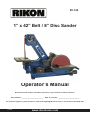
1
50-142
1” x 42” Belt / 8” Disc Sander
Operator’s Manual
Record the serial number and date of purchase in your manual for future reference.
Serial Number: _________________________
Date of purchase: _________________________
For technical support or parts questions, email [email protected] or call toll free at (877)884-5167
50-142M2
www.rikontools.com
SAFETY INSTRUCTIONS
IMPORTANT! Safety is the single most important consideration in the operation of this equipment. The following
instructions must be followed at all times.
There are certain applications for which this tool was designed. We strongly recommend that this tool not be modified and/
or used for any other application other than that for which it was designed. If you have any questions about its application,
do not use the tool until you have contacted us and we have advised you.
General Safety Warnings
KNOW YOUR POWER TOOL. Read the owner’s manual carefully. Learn the tool’s applications, work
capabilities, and its specific potential hazards.
ALWAYS GROUND ALL TOOLS.
If your tool is equipped with a three-pronged plug, you must plug it into a three-hole electric receptacle.
If you use an adapter to accommodate a two-pronged receptacle, you must attach the adapter plug to a
known ground. Never remove the third prong of the plug.
ALWAYS AVOID DANGEROUS ENVIRONMENTS.
Never use power tools in damp or wet locations. Keep your work area well lighted and clear of clutter.
ALWAYS REMOVE THE ADJUSTING KEYS AND WRENCHES FROM TOOLS AFTER USE.
Form the habit of checking to see that keys and adjusting wrenches are removed from the tool before
turning it on.
ALWAYS KEEP YOUR WORK AREA CLEAN. Cluttered areas and benches invite accidents.
ALWAYS KEEP VISITORS AWAY FROM RUNNING MACHINES.
All visitors should be kept a safe distance from the work area.
ALWAYS MAKE THE WORKSHOP CHILDPROOF.
Childproof with padlocks, master switches, or by removing starter keys.
NEVER OPERATE A TOOL WHILE UNDER THE INFLUENCE OF DRUGS,
MEDICATION, OR ALCOHOL.
ALWAYS WEAR PROPER APPAREL.
Never wear loose clothing or jewelry that might get caught in moving parts. Rubber-soled footwear is
recommended for the best footing.
ALWAYS USE SAFETY GLASSES AND WEAR HEARING PROTECTION.
Also use a face or dust mask if the cutting operation is dusty.
NEVER OVERREACH.
Keep your proper footing and balance at all times.
NEVER STAND ON TOOLS.
Serious injury could occur if the tool is tipped or if the cutting tool is accidentally
2
ALWAYS DISCONNECT TOOLS.
Disconnect tools before servicing and when changing accessories such as blades, bits, and cutters.
ALWAYS AVOID ACCIDENTAL STARTING.
Make sure switch is in “OFF” position before plugging in cord.
NEVER LEAVE TOOLS RUNNING UNATTENDED.
ALWAYS CHECK FOR DAMAGED PARTS.
Before initial or continual use of the tool, a guard or other part that is damaged should be checked to
assure that it will operate properly and perform its intended function. Check for alignment of moving
parts, binding of moving parts, breakage of parts, mounting, and any other conditions that may affect its
operation. A guard or other damaged parts should immediately be properly repaired or replaced.
Special Safety Rules For Sanders
1.Do not operate this machine until you have read all of the following instructions.
2.Do not attempt to operate this machine until it is completely assembled.
3. Do not turn ON this machine if any pieces are damaged or missing.
4. If you are not familiar with the operation of the machine, obtain assistance from a qualified
person.
5.It is highly recommended that this machine be mounted on a level surface or stand.
6.Always wear protective eyewear when operating this machine.
7.Do not operate this machine if you are under the influence of drugs and/or alcohol.
8.Do not wear loose clothing or jewelry when operating this machine. Tie back long hair.
9.Do not wear any gloves while operating this machine.
10.Always make sure the power switch is in the OFF position prior to plugging in the machine.
11.Always make sure the power switch is in the OFF position when doing any assembly or setup
operation.
12.Always wear a dust mask and use dust collection when working or cleaning the sander.
13.The use of any accessories or attachments not recommended may cause injury to you and
damage your machine.
14.This machine must be properly grounded.
15. Replace worn, frayed or torn abrasives, as injury to the user, or the machine, may result.
16. Always keep your face and hands clear of moving parts such as belts, discs and pulleys.
California Proposition 65 Warning
WARNING: Some dust created by power sanding, sawing, grinding, drilling, and other construction activities
contains chemicals known to the State of California to cause cancer and birth defects or other reproductive
harm.Your risk from exposure to these chemicals varies, depending on how often you do this type of work. To
reduce your exposure, work in a well-ventilated area and with approved safety equipment, such as dust masks
that are specially designed to filter out microscopic particles.
For more detailed information about California Propostion 65 log onto rikontools.com.
SAVE THESE INSTRUCTIONS.
Refer to them often.
3
TABLE OF CONTENTS
Safety Warnings......................................................................................................................................2-3
Safety Rules for Sanders............................................................................................................................... 3
Specifications.........................................................................................................................................................4
Unpacking and Contents.........................................................................................................................5
Getting to Know Your Sander..........................................................................................................................6
Assembly................................................................................................................................................................ 6-10
Operation......................................................................................................................................11-13
Adjustments..........................................................................................................................................................14-15
Maintenance................................................................................................................................................................16
Wiring Diagram......................................................................................................................................16
Electrical Requirements...................................................................................................................................17
Parts Explosion Diagrams...................................................................................................................................18, 20
Parts Lists............................................................................................................................................................19, 21
Notes....................................................................................................................................22
Warranty.................................................................................................................................................................23
SPECIFICATIONS
Model Number
Belt Size
Belt Speed
Disc Size (PSA)
Disc Speed
Dust Ports (2)
Motor HP
Motor Volts / Amps
Net Weight
50-142
1” x 42”
3,000 FPM
8”
1,725 RPM
1-3/4” & 2”
1/3 HP
110V / 4A
58.5 lbs
This owner’s manual is not a teaching aid and is intended to show
assembly, adjustments, and general use.
NOTE: The specifications, photographs, drawings and information in this manual represent the current
model when the manual was prepared. Changes and improvements may be made at any time, with no
obligation on the part of Rikon Power Tools, Inc. to modify previously delivered units. Reasonable care
has been taken to ensure that the information in this manual is correct, to provide you with the guidelines
for the proper safety, assembly and operation of this machine.
4
CONTENTS OF PACKAGE
Unpacking and Checking Contents
Carefully unpack your sander from its carton, and check to make sure the following parts are
included. If any parts are missing or broken, please call RIKON Customer Service (877-884-5167) as
soon as possible for replacements. DO NOT turn your sander ON if any of these items are missing,
as you may cause injury to yourself or damage to your machine.
B
A
C
E
A. Motor and Base Assembly
B. Belt Housing Assembly
H
K
F
G
C. Belt Sanding Table
D. Motor Belt Cover
E. Disc Sanding Table
F. Sanding Disc, 8”
G. Sandpaper Disc, 8” PSA
I
L
D
J
M
H. V-Belt Rear Cover
I. Dust Port, 2”
J. Disc Dust Cover
K. Miter Gauge
L. Table Lock Handles
N
O
M. Hardware Pack
N. Hex Wrench 2.5MM
O. Hex Wrench 8MM
P. Manual
5
P
GETTING TO KNOW YOUR SANDER
B
O
A
P
G
I
H
C
N
D
Item
A.
B.
C.
D.
E.
F.
G.
H.
E
J
K
F
Description
Item
Sanding Belt 1” x 42”
Sanding Belt Tracking Knob
Sanding Belt Table
Sanding Belt Table Lock Handle
Rubber Machine Feet
ON/OFF Safety Switch
Sanding Disc 8” PSA
Miter Gauge
I.
J.
K.
L.
M.
N.
O.
P.
L
M
Description
Sanding Disc Table
Sanding Disc Table Lock Handle
Sanding Disc Dust Port
Sanding Disc Table Angle Scale
Motor
Sanding Belt Dust Port
Sanding Belt Safety Cover
Motor V-Belt Safety Cover
ASSEMBLY
THE SANDER MUST NOT BE PLUGGED IN AND THE POWER SWITCH
MUST BE IN THE OFF POSITION UNTIL ASSEMBLY IS COMPLETE.
Tools Required for Assembly:
#2 Phillips Screwdriver
Unpacking and Clean-up
1. Carefully finish removing all contents from shipping carton. Compare the contents
of the shipping carton with the list of contents on the previous page. Place parts on a
protected surface for easy identification.
2. Report any shipping damage to your local distributor.
3. Clean all rust protected surfaces. Do not use; gasoline, paint thinner, mineral spirits,
etc. These may damage painted surfaces.
4. Set packing material and shipping carton to the side. Do not discard until the
machine has been set up and is running properly.
6
ASSEMBLY
Always ensure the sander is
unplugged prior to attempting any assembly,
installation or changing of parts and accessories.
ASSEMBLE THE FRAME TO THE BASE
1. Place the Base (Part #61) on a bench and
locate the two elongated holes that will be used
to secure the sanding Frame (#21) to the base.
2. Remove the plastic Cover (#43) from the
frame, by unscrewing the two Knobs (#41). This
will allow you to see the two treaded holes in the
frame for alignment with the base’s holes. FIG. 1
3. Line up the two holes in the frame with the
two holes in the base. From the bottom of the
base, insert the two hex head screws, washers
and lock washers (#70, 71, 72) through the holes
to join them together. You need to tilt the base
up to do this. Hand tighten the nuts. FIG. 2.
4. Do not final tighten at this point.
FIG. 1
FIG. 2
INSTALL THE V-BELT
5. The large drive pulley (#54) is on the motor
arbor and the smaller pulley (#13) is on the arbor
that extends from the frame to drive the sanding
belt. Slip the V-belt onto these pulleys. FIG. 3.
6. Slide the sanding belt frame assembly to
tighten the belt, so there is between 1/4” and
1/2” of deflection, as shown in FIG. 4.
7. Both pulleys should be in-line with each other.
If not, move the frame and/or pulleys to align.
8. Final tighten the sanding frame to the base,
and re-attach the cover (#43). See step 2 above.
FIG. 3
INSTALL THE BELT AND PULLEY GUARD
9. Position the belt & disc Guard (#106) over the
pulleys as shown in FIG. 5.
10. Line up the two holes in the guard with the
holes in the disc cover Casting (#132), and fasten the guard in place with the two M4 pan head
Phillips screws and washers (#104, 105).
11. Do not final tighten the screws at this time,
as you have to adjust the guard to the disc.
NOTE: access to the one screw is through a
pre-cut hole located near the small pulley end.
FIG. 4
7
FIG. 5
ASSEMBLY
INSTALL THE INSIDE BELT GUARD
12. The inside metal cover Guard (#108) fits
between the motor and the belt guard (#106).
13. Position the metal guard inside of the belt
guard. The bent tabs will keep it in place, then
secure it with the long M4 Phillips head screw
(#102) and wing nut (#109). FIG. 6.
FIG. 6
INSTALL THE SANDING DISC
14. Make sure the metal Sanding Disc (#100)
is clean of foreign material.
NOTE: This disc only takes PSA (pressure
sensitive adhesive) sanding abrasives.
15. Peel the protective backing from the
supplied Sandpaper Disc (#99), center it on the
metal disc, and press it in place.
16. Install the sanding disc onto the motor
arbor. Line up the disc’s keyway to the motor’s
shaft key and slide the disc in place. Align the
disc up with the disc guard so it is slightly proud
of the cover. This enables the workpiece to
pass by it without rubbing.
17. Tighten the disc onto the motor shaft with
the pre-installed hex screw (#101). You can get
access to it through the hole in the cover guard.
FIG. 7.
FIG. 7
INSTALL THE DUST PORT
18. Attach the Dust Port (#127) to the sanding
disc base using the M6 Phillips head screw and
lock washer (#128, 129). FIG. 8.
19. The Dust Port has a 1-3/4” internal diameter, and 2” outer diameter for use with a 2”
flex hose to your dust collector.
FIG. 8
INSTALL THE LOWER DISC GUARD
20. Attach the metal, lower Disc Guard (#130)
to the sanding disc base with the three M4
Phillips head screws and washers (#131, 63).
FIG. 9.
8
FIG. 9
ASSEMBLY
INSTALL THE DISC SANDING TABLE
CURVED KEYWAY
21. An adjustable Handle and Washer (#47,
125) are supplied to hold the Sanding Disc
Table (#120) in position on the sanding base.
22. Line the disc sanding table’s slotted right
end with the curved keyway in the sanding
disc base. Position it in the keyway so that
the handle can be installed, fastening the
parts together. FIG. 10.
NOTE: It is easier to thread the bolt part
of the handle on first, then attach the handle
to it using the spring loaded Allen head cap
screw provided.
23. Attach the Angle Scale Pointer (#133) to
the sanding disc frame with the M4 Phillips
pan head screw and washer (#134, 128). The
pre-drilled hole is located just below the angle
gauge. FIG. 11.
Adjust the pointer after the table is set
to 90°, see page 14.
The disc table will tilt from 45° to 90°. FIG. 12.
FIG. 10
ANGLE SCALE &
POINTER
FIG. 11
INSTALL THE BELT SANDING TABLE
24. An adjustable Handle and Washer (#47,
48) are supplied to hold the Sanding Belt
Table (#45) in position on the Sanding
Frame (#21).
25. Position the sanding belt table around
the belt, and so that it’s lower bracket with
the curved slot is in postion with the threaded
hole in the frame.
26. Fasten the table in place. Thread the
bolt portion of the locking adjustable handle
through the bracket’s slot and into the threaded hole of the sanding frame. FIG. 13.
The table will tilt from 45° to 90°. FIG. 14.
NOTE: See pages 13 and 14 for addtional
information on adjusting the sanding tables.
Tables should be adjusted to
a distance of about 1/16” away from the sanding disc or belt to prevent accidents if work
or your fingers get stuck in the gap while the
sander is running.
FIG. 12
FIG. 13
9
FIG. 14
ASSEMBLY
Always ensure the sander is
unplugged prior to attempting any assembly,
installation or changing of parts and accessories.
Lag Bolt
Machine Bolt
MOUNTING THE SANDER
TO A WORKBENCH OR STAND
Washer
CAUTION: If during operation there is any
tendency for the sander to tip over, slide or walk
on the supporting surface, the sander should be
properly mounted to a workbench or stand.
Rubber Foot
Workbench
Washer
Lock Washer
1. Rubber feet are fastened to this sander prior
to shipping. They may, or may not, be used when
attaching the sander to a bench or stand.
2. Position the sander on the workbench.
3. There are two options for mounting the sander
to the workbench:
- Use the two extra holes in the base (located by
the front right foot, and rear left foot when looking
at the sanding belt table);
- Use the four holes that are securing the
rubber feet. The bolts will have to be removed
and replaced with other fasteners to go through
the sander’s base and feet. See Figure 15 for
illustrations of each method.
4. Mark the workbench through the selected
mounting holes located in the sander’s base, per
above.
5. Drill holes in the workbench at the marks.
6. Using long bolts, washers, lock-washers and
nuts; or lag bolts; (fasteners not supplied), secure
the sander to the workbench. FIG. 15.
Pilot Hole for
Lag Bolt
Nut
FIG. 15
TEST RUNNING THE SANDER
With the sander fully assembled and checked
to make sure that all parts and fasteners are
secure, test run the sander to confirm that it
runs smoothly. If any adjustments are needed,
these must be done with the machine turned off
and unplugged for safety.
If you have any questions regarding assembly
before operating the sander, contact RIKON
Tech Support at 877-884-5167 for assistance.
California Proposition 65 Warning
WARNING: Some dust created by power sanding, sawing, grinding, drilling, and other
construction activities contains chemicals known to the State of California to cause cancer
and birth defects or other reproductive harm.Your risk from exposure to these chemicals
varies, depending on how often you do this type of work. To reduce your exposure, work in a
well-ventilated area and with approved safety equipment, such as dust masks that are
specially designed to filter out microscopic particles.
For more detailed information about California Propostion 65 log onto rikontools.com.
10
OPERATION
When sanding, always position
your work on the downward, rotating side (left
side) of the sanding disc. FIG. 16. The sanding
action will then force the wood down, safely
towards the table, where it can be controlled.
Sanding on the right, upward rotating side of the
disc is dangerous, as your work cannot be controlled and ‘kick-back’ may occur - the wood being
forced up and out of your hands.
FIG. 16
Always ensure the sander is
unplugged prior to attempting any assembly,
installation or changing of parts and accessories.
DISC SANDING
1. Depending on what type of sanding that you
will be doing, set the Sanding Disc Table to the
proper angle from 45° to 90°.
2. Once the table has been set for the correct
sanding angle, and all fasteners are secure, the
machine can be plugged in for operation.
3. Use the Miter Gauge (#110) for added control
of the workpiece during sanding. The miter gauge
can also be set to various degree angles for maintaining accurate angles when sanding small or
multiple parts.
4. Do not force the workpiece into the sanding
disc. Sand using light pressue, letting the sanding
abrasives time to do their work!
5. Move your workpiece slightly left and right on
the disc, keeping to the left-of-center, downward
side. This will help prevent resin or debris from
building up on one area of the disc, and also helps
to prevent burning of the sanded surface from
excessive abrasive-action heat build-up.
FIG. 17
NOTE: It is strongly recommended that users
employ a dust-collection system when using this
belt & disc sander. Use of a dust mask or respirator
is still recommended, even when a dust-collection
system is in use.
11
FIG. 18
OPERATION
Always ensure the sander is
unplugged prior to attempting any assembly,
installation or changing of parts and accessories.
BELT SANDING
1. Depending on what type of sanding that you
will be doing, set the Sanding Belt Table to the
proper angle from 45° to 90° with a protractor, or
other angle measuring tool or pre-cut sample.
2. Once the table has been set for the correct
sanding angle, and all fasteners are secure, the
machine can be plugged in for operation.
3. Use the Miter Gauge (#110) for added control
of the workpiece during sanding. The miter gauge
can also be set to various degree angles for maintaining accurate angles when sanding small or
multiple parts.
4. Do not force the workpiece into the sanding
belt. Sand using light pressue, letting the sanding
abrasives time to do their work!
5. Move your workpiece slightly left and right on
the belt. This will help prevent resin or debris from
building up on one area of the belt, and also helps
to prevent burning of the sanded surface from
excessive abrasive-action heat build-up.
6. The Platen (#30) supports the back of the
sanding belt and offers a flat surface to sand or
sharpen against. It should be positioned so it is
almost touching the back of the sanding belt.
7. To adjust the platen, loosen the hex Screw
(#27) at the rear of the platen. FIG. 20.
8. The platen can also be removed for contour
sanding or polishing.
FIG. 19
FIG. 20
TRACKING
KNOB
DRIVE WHEEL
SANDING BELT TRACKING
1. Belt tracking on the center of the drive wheels
is pre-set at the factory. If an adjustment need to
be made, the sander must be turned on.
2. Slowly turn the Belt Tracking Knob (#5) to
correct the tracking of the belt - left or right as
needed - so that the belt finally rides on the center
of the top drive wheel (#23). FIG. 21.
12
FIG. 21
OPERATION
Always ensure the sander is
unplugged prior to attempting any assembly,
installation or changing of parts and accessories.
CHANGING THE SANDING BELT
1. Remove the plastic Cover (#43) from the
frame by unscrewing the two knobs (#41).
2. Tilt the sanding belt table forward to 45° so
that there is ample space between the platen and
rear of the table to remove the belt.
3. Press down on the tracking knob (FIG. 21) to
compress the spring tension, and then be able to
slide the sanding belt off the three pulleys.
4. Install a new sanding belt by compressing the
tracking knob and sliding the new belt onto the
three drive wheels.
NOTE: Follow the directional arrows that are
printed on the back of the sanding belt. The belt
is to rotate down towards the sanding table.
See FIG. 22.
5. Re-attach the safety cover onto the frame with
the two knobs.
6. Check the belt tracking to ensure that the belt
is riding on the center of the drive wheels. See
page 12 for the belt tracking procedures.
SANDING
BELT
DIRECTION
FIG. 22
CHANGING THE SANDING DISC
1. Remove and set aside the miter gauge.
2. Remove the sanding disc table.
3. Peel the used abrasive disc from the metal
sanding disc plate. FIG. 23.
4. Make sure that the disc plate is clean of any
residue.
5. Peel the protective backing from the new PSA
8” abrasive sanding disc.
6. Center and press the new 8” PSA sanding disc
firmly onto the disc plate.
7. Replace the sanding table and handle that
were removed in step 2.
13
FIG. 23
NOTE: Hook & Loop sanding discs cannot
be used with this sander! Only 8” sanding discs with pressure sensitive adhesive
(PSA) backing can be used.
ADJUSTMENTS
DISC TABLE ADJUSTMENTS
Ensure sander is disconnected from the power
supply prior to commencing work.
1. To check the trueness of the 90º angle of
the disc sanding table, place a square or other
measuring device on the table with the other
end against the sanding disc. FIG. 24.
2. Loosen the disc table adjustment handle
(#47), and adjust table angle to 90º.
3. Re-tighten the disc table adjustment handle.
4. Adjust the Angle Scale Pointer (#133) to 0°.
5. To adjust the disc table to another angle,
loosen the disc table adjustment handle.
6. Set the table at the desired angle using the
angle scale pointer.
7. Re-tighten the disc table adjustment handle.
FIG. 24
BELT TABLE ADJUSTMENTS
Ensure sander is disconnected from the power
supply prior to commencing work.
FIG. 25
For most sanding operations, the table will likely
remain at a 90º angle to the belt. A positive stop
is provided with your sander to ensure fast
positioning of the table at 90 degrees to the belt.
1. Loosen the table-locking handle (#47).
2. Position the table back to the platen so there
is about 1/16” space between it and the belt.
3. Using a square, protractor or other 90º tool,
measure the angle of the table against the
platen (#30). FIG. 26. Once the 90º is setting is
found, lock it in place, then adjust the hex nut
Stop (#46), that is under the table.
4. To set the table to a different angle, loosen
the handle and tilt the table forward until it is at
the required angle. FIG. 27.
5. Tighten the handle to lock the table in postion
for sanding.
NOTE: To get the full range of table angling,
handle must be very loose, so that it slides
along the slot in the table bracket. The table can
then be moved back to get maximum angles.
TABLE
STOP
SET SCREW
FIG. 26
14
FIG. 27
ADJUSTMENTS
V-BELT TENSION ADJUSTMENTS
Ensure sander is disconnected from the power
supply prior to commencing work.
Should the rotation of the sanding belt or disc
slow down or stall, the cause may be that the
V-belt is slipping on the two pulleys. This may be
because the motor or frame have become loose
from the base, or that the V-belt has stretched
out due to the machine being used. In either
case, re-adjustment of the V-belt is needed.
FIG. 28
1. To gain access to the V-belt, remove the Vbelt rear metal cover (#108) and V-Belt & Disc
Guard (#106).
NOTE: For clarity, FIG. 28 shows the V-belt
and pulleys with the metal sanding disc plate,
table assembly and lower disc guard removed.
2. Tilt the sander back, and slightly loosen the
two hex head screws (#72) so that the sanding Frame (#21) can be moved a bit forward or
backwards to tension the V-belt. FIG. 29.
3. Position the frame so the tension on the
V-belt is about 1/4” to 1/2” deflection when moderate pressure is applied to the belt. FIG. 30.
4. Tighten the hex head bolts to secure the
frame in its new position on the base.
5. Re-install the safety guards over the V-belt,
in step 1 above. See page 7 for the installation
process, if needed.
LOOSEN BOLTS
FIG. 29
FIG. 30
MITER GAUGE ADJUSTMENTS
A Miter Gauge (#110) is supplied with your
sander, and can be used on the disc or belt
tables, which have slots in their design to fit
the miter gauge’s bar. The miter gauge head
can be set anywhere up to 45º (right or left) by
loosening the lock-knob, setting the miter gauge
head to the desired angle, and retightening the
lock-knob. FIG. 31.
15
FIG. 31
MAINTENANCE
Turn the power switch “OFF” and disconnect the plug from the outlet prior to
adjusting or maintaining the sander. DO NOT attempt to repair or maintain the electrical components
of the motor. Take the sander to a qualified service technician for this type of maintenance.
MAINTENANCE REQUIREDFREQUENCY
1.
Check the power cord for any damage.
Before each use.
2.
Check sanding belts and discs for damage or wear.
Before each use.
3.
Check all guards and hardware to make sure they are secure.
Before each use.
4.
Check all moving parts for alignment and binding issues.
Before each use.
4.
Dress/Clean sanding surfaces for best abrasive action.
As needed
5.
Replace sanding belts or discs when worn or damaged.
As needed.
6.
Clean and vacuum dust from the motor housing and other sander parts. As needed.
7.
Keep iron tables free of rust. Apply coat of paste wax or silicon spray.
As needed.
NOTE: Lubrication of the bearings is not necessary, as they are sealed and pre-lubricated for life.
Just replace a bearing if failure occurs. Do not use compressed air near bearings. Simply wipe the
exposed bearing surfaces with a dry cloth to clean them.
Service beyond recommended maintenance on these tools should only be performed by an
authorized, qualified technician.
WIRING DIAGRAM
This machine must be grounded. Replacement of the power supply
cable should only be done by a qualified electrician.
16
ELECTRICAL REQUIREMENTS
In the event of a malfunction or breakdown, grounding provides a path of least resistance for electric current
to reduce the risk of electric shock. This tool is equipped with an electric cord having an equipment-grounding
conductor and a grounding plug. The plug must be plugged into a matching outlet that is properly installed and
grounded in accordance with all local codes and ordinances. Do not modify the plug provided. If it will not fit the
outlet, have the proper outlet installed by a qualified electrician.
Improper connection of the equipment-grounding conductor can result in a risk of electric shock. The conductor,
with insulation having an outer surface that is green with or without yellow stripes, is the equipment-grounding
conductor. If repair or replacement of the electric cord or plug is necessary, do not connect the equipment-grounding
conductor to a live terminal. Check with a qualified electrician or service personnel if the grounding instructions are
not completely understood, or if in doubt as to whether the tool is properly grounded.
Use only three wire extension cords that have three-prong grounding plugs and three-pole receptacles that accept
the tool’s plug.* Repair or replace a damaged or worn cord immediately.
This tool is intended for use on a circuit that has an outlet that looks the one illustrated in Figure A below. The tool
has a grounding plug that looks like the grounding plug as illustrated in Figure A below. A temporary adapter, which
locks like the adapter as illustrated in Figure B below, may be used to connect this plug to a two-pole receptacle, as
shown in Figure B if a properly grounded outlet is not available.** The temporary adapter should only be used until
a properly grounded outlet can be installed by a qualified electrician. The green colored rigid ear or tab, extending
from the adapter, must be connected to a permanent ground such as a properly grounded outlet box.
* Canadian electrical codes require extension cords to be certified SJT type or better.
** Use of an adapter in Canada is not acceptable.
EXTENSION CORDS
Keep the extension cord clear of the working area. Position the cord so that it will not get
caught on lumber, tools or other obstructions while you
are working with a power tool. Check extension cords
before each use. If damaged replace immediately.
Never use a tool with a damaged cord, since touching
the damaged area could cause electrical shock, resulting
in serious injury.
Use a proper extension cord. Only use cords listed by Underwriters Laboratories (UL). Other extension cords can cause a
drop in line voltage, resulting in a loss of power and overheating of tool. When operating a power tool outdoors, use an
outdoor extension cord marked “W-A” or “W”. These cords are
rated for outdoor use and reduce the risk of electric shock.
17
PARTS EXPLOSION
SANDING BELT & MOTOR
5
6
2
7
3
22
23
8
1
9
24
25
4
12
13
26
18
10
28
11
16
46
27
14
15
45
29
47
30
17
19
33
51
34
21
53
36
49
50
32
20
48
37
52
38
35
39
54
38
55
39
56
56-B
57
58
41
56-A
59
62
41
64
63
43
65
66
61
67
80
68
60
70
71
69
72
18
81
PARTS LIST
KEY
NO.
1
2
3
4
5
6
7
8
9
10
11
12
13
14
15
16
17
18
19
20
21
22
23
24
25
26
27
28
29
30
32
33
34
35
36
37
DESCRIPTION
MFG.
PART NO.
KEY
NO.
DESCRIPTION
MFG.
PART NO.
Hex Socket Head Screw M10
Flat Washer 10mm
Spring
Spacer
Belt Tracking Knob & Screw
Spring
Support Bracket
Pin
Shaft
Shaft
Hex Screw M5
Hex Screw M5
Drive Pulley
Retaining Plate
Screw M4
Washer 4mm
Ball Bearing 6202
Key C5
Shaft
Ball Bearing 6002
Frame
Ball Bearing 6202
Drive Wheel
Flat Washer
6mm
Lock Washer 6mm
Screw M6
Screw M10
Lock Washer 10mm
Flat Washer
10mm
Platen
Ball Bearing
6202
Drive Wheel
Retaining Ring 15mm
Hex Screw M5
Drive Wheel
Sanding Belt 1” × 42”
P50-142-1
P50-142-2
P50-142-3
P50-142-4
P50-142-5
P50-142-6
P50-142-7
P50-142-8
P50-142-9
P50-142-10
P50-142-11
P50-142-12
P50-142-13
P50-142-14
P50-142-15
P50-142-16
P50-142-17
P50-142-18
P50-142-19
P50-142-20
P50-142-21
P50-142-22
P50-142-23
P50-142-24
P50-142-25
P50-142-26
P50-142-27
P50-142-28
P50-142-29
P50-142-30
P50-142-32
P50-142-33
P50-142-34
P50-142-35
P50-142-36
P50-142-37
38
39
41
43
45
46
47
48
49
50
51
52
53
54
55
56
56A
56B
57
58
59
60
61
62
63
64
65
66
67
68
69
70
71
72
80
81
Nut
M6
Screw M6
Knob
Cover
Sanding Belt Table
Hex Screw M5
Handle Assembly
Flat Washer 10mm
Sanding Belt Table Bracket
Flat Washer 10mm
Lock Washer 10mm
Screw M8
Hex Screw M5
Drive Pulley
Key C5
Motor 1/3HP
Capacitor
Capacitor Cover
Nut M8
Lock Washer 8mm
Flat Washer
8mm
Screw M8
Base
Screw
M4
Washer 4mm
Screw
M8
Lock Washer 8mm
Flat Washer
8mm
Rubber Foot
Flat Washer 8mm
Nut M8
Flat Washer 10mm
Lock Washer 10mm
Screw
M10
Allen Wrench 2.5mm
Allen Wrench 8mm
P50-142-38
P50-142-39
P50-142-41
P50-142-43
P50-142-45
P50-142-46
P50-142-47
P50-142-48
P50-142-49
P50-142-50
P50-142-51
P50-142-52
P50-142-53
P50-142-54
P50-142-55
P50-142-56
P50-142-56A
P50-142-56B
P50-142-57
P50-142-58
P50-142-59
P50-142-60
P50-142-61
P50-142-62
P50-142-63
P50-142-64
P50-142-65
P50-142-66
P50-142-67
P50-142-68
P50-142-69
P50-142-70
P50-142-71
P50-142-72
P50-142-80
P50-142-81
NOTE: Please reference the Manufacturer’s Part Number when calling for Replacement Parts.
For Parts under Warranty, the Serial Number of your machine is required.
19
PARTS EXPLOSION
SANDING DISC & SWITCH
99
100
102
104
101
105
106
110
107
108
109
120
131
123
121
139
130
124
125
137
63
132
141
140
122
47
143
127
128
129
136
135
58
144
142
133
134
61
60
NOTE: Please reference the Manufacturer’s Part Number when calling for Replacement Parts.
For Parts under Warranty, the Serial Number of your machine is required.
20
PARTS LIST
KEY NO.
47
58
60
61
63
99
100
101
102
104
105
106
107
108
109
110
120
121
122
123
124
125
127
128
129
130
131
132
133
134
135
136
137
139
140
141
142
143
144
DESCRIPTION
Handle Assembly
Lock Washer 8mm
Screw
M8
Base
Washer 4mm
Sandpaper Disc 8” PSA
Sanding Disc Plate 8”
Hex Screw M5
Screw M4
Screw M4
Washer 4mm
Belt & Disc Guard
V- Belt GB/T1171-2006 Z 460
Inside Cover Guard
Wing Nut M4
Miter Gauge
Sanding Disc Table
Pin
Arc Key
Angle Scale
Rivit
Flat Washer 10mm
Dust Port 2” O.D.
Washer 6mm
Screw
M6
Disc Guard
Screw
M4
Sanding Disc Base
Angle Scale Pointer
Screw
M4
Nut
M10
Washer 10mm
Switch
Switch Cover
Screw M4
Power Cord
Cord Bushing
Screw M4
Cord Clamp
21
MFG. PART NO.
P50-142-47
P50-142-58
P50-142-60
P50-142-61
P50-142-63
P50-142-99
P50-142-100
P50-142-101
P50-142-102
P50-142-104
P50-142-105
P50-142-106
P50-142-107
P50-142-108
P50-142-109
P50-142-110
P50-142-120
P50-142-121
P50-142-122
P50-142-123
P50-142-124
P50-142-125
P50-142-127
P50-142-128
P50-142-129
P50-142-130
P50-142-131
P50-142-132
P50-142-133
P50-142-134
P50-142-135
P50-142-136
P50-142-137
P50-142-139
P50-142-140
P50-142-141
P50-142-142
P50-142-143
P50-142-144
NOTES
Use this section to record maintenance, service and any calls to Technical Support:
22
WARRANTY
23
50-142
For more information:
16 Progress Rd
Billerica, MA 01821
877-884-5167 / 978-528-5380
[email protected]
50-142M2
www.rikontools.com