1
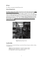
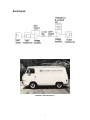
Model 2-610
Dual Channel
Tube Preamplifier
Universal Audio Part Number 65-0008
Revision 1.2/WS
i
The 2-610 Dual Channel Tube Preamplifier
Thank you for purchasing the 2-610 Dual Tube Microphone Preamplifier. The 2-610 is inspired by the
microphone preamp section of the 610 console designed by my father, M.T. “Bill” Putnam, in 1960. The 610 was
a rotary-control console and was the first console of a modular design. Although technologically simple
compared to modern consoles, the 610 possessed a warmth and character that kept it in demand for decades.
As a prominent part of my father’s United/Western Studios, the 610 was used on many classic recordings by
Frank Sinatra and Sarah Vaughan. The Beach Boys Pet Sounds, the Doors LA Woman, and Van Halen’s debut
album were all recorded on the 610. The legendary Wally Heider used the 610 in his remote truck for many of his
best known live recordings. At Ocean Way Studios (formerly United), the 610 is lovingly preserved and still used
in Studio B.
Most of us at Universal Audio are musicians, recording engineers, or both, and we wanted to build a mic preamp
that we’d be delighted to use ourselves. We love the recording process, and we really get inspired when the
basic tracks are beautifully recorded. Our design goal for the 2-610 was to capture the original character of the
610, creating a preamp that would induce that “a-ha” feeling we’ve felt when hearing music recorded in its
most natural, inspired form.
The controls of the 2-610 are simple and essential: we added only those features required for practical use
without needless duplication of functionality found elsewhere in most studios. The transformers and tubes
received much of our R&D attention. We settled on a transformer design featuring double-sized alloy cores with
custom windings. Our tubes are carefully selected and tested individually. This extra effort is well worth the
time and cost because the result is a truly outstanding, easy-to-use mic preamp!
These products have been quite an enjoyable adventure to develop and we’re sure the next phase will be even
more fun! We thank you for your support and we thank my father, Bill Putnam.
-Bill Putnam Jr.
Wally Heider’s Remote Recording Rig, with 610 Console
In addition to the 2-610, Universal Audio has released reproductions of the classic Teletronix LA-2A Leveling
Amplifier and 1176LN Limiter as well as the remaining 610 tube preamp family of products such as the TEC
Award winning 6176 and LA-610. Modern tools such as the flagship 4110 & 8110 Precision Microphone
Preamplifiers bring tonal flexibility to the multi-channel mic preamp, while the Desktop Console Series Remote
Preamp and Monitor Master bring large format console features to desktop recordists. Universal Audio also
creates software emulations of vintage hardware and innovative mixing tools that run on our UAD DSP platform.
All of these products are designed to meet the demands of the modern recording studio, yet retain the character
and quality of vintage equipment. See more at www.uaudio.com, including the SOLO mic pre series, and 2192
Master Audio Interface A/D and D/A.
ii
IMPORTANT SAFETY INSTRUCTIONS
Before using this unit, be sure to carefully read the applicable items of these operating instructions and the
safety suggestions. Afterwards keep them handy for future reference. Take special care to follow the warnings
indicated on the unit, as well as in the operating instructions.
1. Water and Moisture – Do not use the unit near any source of water or in excessively moist environments.
2. Object and Liquid Entry – Care should be taken so that objects do not fall, and liquids are not spilled, into
the enclosure through openings.
3. Ventilation – When installing the unit in a rack or any other location, be sure there is adequate ventilation.
Improper ventilation will cause overheating, and can damage the unit.
4. Heat – The unit should be situated away from heat sources, or other equipment that produce heat.
5. Power Sources – The unit should be connected to a power supply only of the type described in the
operating instructions, or as marked on the unit.
6. Power Cord Protection – AC power supply cords should be routed so that they are not likely to be walked
on or pinched by items placed upon or against them. Pay particular attention to cords at plugs,
convenience receptacles, and the point where they exit from the unit. Never take hold of the plug or cord if
your hand is wet. Always grasp the plug body when connecting or disconnecting it.
7. Grounding of the Plug – This unit is equipped with a 3-wire grounding type plug, a plug having a third
(grounding) pin. This plug will only fit into a grounding-type power outlet. This is a safety feature. If you are
unable to insert the plug into the outlet, contact your electrician to replace your obsolete outlet. Do not
defeat the purpose of the grounding-type plug.
8. Cleaning – The unit should be cleaned only as recommended by the manufacturer.
9. Nonuse Periods – The AC power supply cord of the unit should be unplugged from the AC outlet when left
unused for a long period of time.
10. Damage Requiring Service – The unit should be serviced by a qualified service personnel when:
a. The AC power supply cord or the plug has been damaged: or
b. Objects have fallen or liquid has been spilled into the unit; or
c. The unit has been exposed to rain; or
d. The unit does not operate normally or exhibits a marked change in performance; or
e. The unit has been dropped, or the enclosure damaged.
11. Servicing – The user should not attempt to service the unit beyond that described in the operating
instructions. All other servicing should be referred to qualified service personnel.
iii
Notice
This manual provides general information, preparation for use, installation and operating instruction
for the Universal Audio 2-610 Microphone Preamplifier.
The information contained in this manual is subject to change without notice. Universal Audio, Inc.
makes no warranties of any kind with regard to this manual, including, but not limited to, the implied
warranties of merchantability and fitness for a particular purpose. Universal Audio, Inc. shall not be
liable for errors contained herein or direct, indirect, special, incidental, or consequential damages in
connection with the furnishing, performance, or use of this material.
Copyright
© 2007 Universal Audio, Inc. All rights reserved.
This manual and any associated software, artwork, product designs, and design concepts are subject
to copyright protection. No part of this document may be reproduced, in any form, without prior written
permission of Universal Audio, Inc.
Contents
This package should contain:
2-610 Preamplifier
2-610 Manual
IEC Power Cable
Registration Card
Warranty
Warranty for the 2-610 and all Universal Audio hardware is one year, parts and labor.
Trademarks
2-610, LA-2A, 1176LN, 6176, LA-610, 4110, 8110, DCS Remote Preamp, DCS Monitor Master, 2192,
UAD and the Universal Audio, Inc. logo are trademarks of Universal Audio, Inc. Other company and
product names mentioned herein are trademarks of their respective companies
iv
Table of Contents
Performance and Audio Specifications................................................................................................................ 1
Preamp Operation Instructions .......................................................................................................................... 2
2-610 Front Panel................................................................................................................................................ 2
Input Select ........................................................................................................................................................ 3
Mic ..................................................................................................................................................... 3
Hi-Z .................................................................................................................................................... 3
Line .................................................................................................................................................... 3
Gain .................................................................................................................................................................... 3
Level................................................................................................................................................................... 3
-15 dB Pad .......................................................................................................................................................... 4
Polarity............................................................................................................................................................... 4
EQ Controls......................................................................................................................................................... 4
Frequency........................................................................................................................................... 4
Boost/Cut........................................................................................................................................... 4
+48 V.................................................................................................................................................................. 4
Power ................................................................................................................................................................. 5
2-610 Rear Panel................................................................................................................................................. 5
Input/Output....................................................................................................................................................... 5
AC Power ............................................................................................................................................................ 6
Internal Voltage Selector..................................................................................................................................... 6
Fuse/Mains/Bulbs ............................................................................................................................................... 6
Block Diagram .................................................................................................................................................... 7
Historical Notes.................................................................................................................................................. 8
The 610 Preamp.................................................................................................................................. 8
The 1176LN Limiting Amplifier and LA-2A Leveling Amplifier............................................................................... 9
The 1176LN......................................................................................................................................... 9
The LA-2A ........................................................................................................................................... 9
v
2-610 Specifications
Microphone Input Impedance
Selectable, 500 or 2k
Balanced Line Input Impedance
13.8 k
Hi-Z Input Impedance
Selectable between 2.2 M or 47 k
Maximum Microphone Input Level
+3.5 dBu
Maximum Output Level
+20 dBm
Internal Output Impedance
60 Recommended Minimum Load
600 Frequency Response
20 Hz to 20 kHz +1 dB
Maximum Gain
61 dB
Signal-to-Noise Ratio
Greater than 82 dB
Tube Complement
One 12AX7 and one 12AT7 per channel
Power Requirements
115V/230V
Power Consumption
30 watts
Dimensions
2-610 Weight
19”W x 3.5”H x 12.25”D
12.25 lb.
1
Preamp Operating Instructions
The 2-610 is a two-channel, vacuum-tube microphone/instrument/line preamplifier. Each channel has
two gain stages that each utilizes a dual-triode tube operating in a class A single-ended
configuration. Variable negative feedback is applied to both of these stages to control gain, distortion,
and frequency response. Balanced inputs and outputs are transformer coupled.
2-610 Front Panel
The front panel has two identical channels (figure 1) each with Input Select, Gain, Level, EQ, Pad and
Polarity controls as well as a Hi-Z Input. The center section between the channels (figure 2) has the
Power On/Off switch and light and a 48 V phantom power On/Off switch for each channel. Each control
is discussed in the following sections.
GAIN
POLARITY
HIGH FREQUENCY
PAD
-5
GAIN
0 +5
-10
HIGH BOOST/CUT
+10
LEVEL
-15 dB
PAD
2.0K
500
Line
Hi-Z
OUT ø
5
3
INø
-3
10K
6
+4.5
-6
4.5K
7
+3
-4.5
+6
-9
2
8
LOW
47K
2.2M
-1.5 0 +1.5
7K
4
Mic
HIGH
1
9
0
10
-1.5 0 +1.5
100
200
-3
+3
-4.5
70
+4.5
-6
Hi-Z
INPUT SELECT
+6
-9
LEVEL
INSTRUMENT INPUT
+9
LOW BOOST/CUT
LOW FREQUENCY
Figure 1: 2-610 front panel channel controls
2
+9
Input Select
The input select switch determines which input is active: Mic, Line, or Hi-Z. Both the Mic and Hi-Z
inputs include two settings to select between unique input impedances.
Mic
Selects the signal input from the balanced rear panel MIC INPUT connection. The impedance for the
MIC INPUT can be set to 500 or 2.0K . Switching between these two positions while listening to a
connected microphone may reveal a different tonal quality and/or gain difference. Typically a
microphone preamplifier should have input impedance roughly equal to about 10 times the
microphone output impedance. For example, if your microphone has output impedance between 150 and 200 , set the switch to the 2.0K position. However, since making music is not necessarily about
adhering to technical specifications, feel free to experiment with the settings to attain the desired
sound. You will not harm your microphone or the 2-610.
Hi-Z
Selects the signal input from the unbalanced front panel Hi-Z ¼” connection. The impedance for the
Hi-Z input can be set to 47K or 2.2M and is intended for electric guitar, electric bass, or any
instrument with a magnetic or acoustic transducer pickup. The 47K setting is best suited for -10
dBv level signals, typically found on active basses and guitars. The 2.2M setting is appropriate for
instruments with passive pickup systems. Since an instrument’s output impedance may be somewhere
between the active and passive levels, feel free to experiment to achieve the best sound at the desired
level.
Line
Selects the signal input from the balanced rear panel LINE INPUT connection. LINE INPUT has an input
impedance of approximately 13K and is intended to accommodate mixers, tape machines, other mic
preamps or any device with a line level output, such as keyboards, sound modules and drum
machines. The 2-610 may be used as a “tone box” in this configuration, offering a variety of sonic
colors based on the front panel control settings.
Gain
Adjusts the gain of the input stage in 5 dB increments. Turning the Gain switch clockwise reduces the
negative feedback, which raises the gain. In addition to changing the input volume, the Gain switch
also alters the amount of the input tube’s harmonic distortion, a major contribution to the warm sound
characteristic of tube equipment. The greater the gain, to more color the 2-610 will impart to the
recorded signal.
Level
The Level knob determines the amount of signal from the preamplifier gain stage sent to the output
stage. For the cleanest, most uncolored signal from the 2-610, set the Gain switch to a lower setting
(-10 or -5) while turning the Level knob until the appropriate output signal is attained. Altering the
Gain, Impedance, and Output controls together provides many useful tonal variations.
Note: The numeric values for the Level knob are NOT specific dB values.
3
-15 dB PAD
Reduces the input signal by -15dB; Recommended in reducing the incoming signal in cases where
undesired distortion is present at low gain levels.
Polarity
The front panel toggle switch labeled IN ø and OUT ø determines the polarity of the LINE OUTPUT. When
IN ø is selected, pin 2 is hot (positive). When OUT ø is selected, pin 3 is hot (positive). Polarity reversal
may be useful in cases where more than one microphone is utilized in recording a source.
EQ Controls
The 2-610 has both low and high frequency shelving-type equalizers, each with two controls.
Frequency
This toggle switch selects the corner frequency for each of the filters. High: 4.5K, 7K, 10K;
100, 200.
Low: 70,
Boost/Cut
This switch selects the amount of boost or cut applied to the frequency shelf. The positive and
negative numbers on the front panel denote dB values(-9, -6 -4.5, -3, 1.5, 0, 1.5, 3, 4.5, 6, 9).
+48 V
Most modern condenser microphones often require +48 phantom voltage to operate. Each channel of
the 2-610 has a toggle switch that applies 48 V to the MIC INPUT when the switch is up. It is good
practice to keep phantom power off (switch down) when it is not required. To avoid loud transients,
always keep phantom power off when connecting or disconnecting microphones. It is recommended
that the power requirements of your microphone be checked with the manufacturer before applying
phantom power.
Figure 2: 2-610 front panel center section
4
Power
The 2-610 provides the user with a front panel power switch. It is recommended to power off the unit
when the 2-610 is not used for extended periods of time.
2-610 Rear Panel
The rear panel (figure 3) has two identical channels each with MIC INPUT, LINE INPUT, and LINE
OUTPUT XLR connectors. The center of the rear panel has an AC Power input with a fuse holder and a
voltage selector switch. These connectors and controls are discussed in the following sections.
Figure 3: 2-610 rear panel
Figure 4: Detail of 2-610 rear panel
Input/Output
Standard XLR input and output connectors are provided on the rear panel. Pin 2 is wired positive (hot)
on the LINE and MIC INPUTS> Pin 2 is positive on the LINE OUTPUT when the front panel Polarity toggle
switch is down (IN ø). Pin 3 is positive on the LINE OUTPUT when the front panel Polarity switch is up
(OUT ø).
5
AC Power
The 2-610 uses a standard, detachable IEC power cable.
Internal Voltage Selector
The 2-610 can operate at 115V or 230V. To change the mode, wait 5 minutes after power down, unplug
the AC power cord from the rear chassis. Remove the top cover. As shown below, there is a connector
that can be plugged in to one location or another location to configure the unit for 115V or 230V
operation. This figure shows the unit configured for 230V operation. The connector can be identified by
it’s wire colors; Black, Blue, White, Orange. This connector should be plugged into location H8 for 230V
operation and location H6 for 115V operation. The connector is part of the wiring that comes from the
power transformer located at rear center of the 2-610. When changing operating voltage, fuse value
must be changed as well. Make sure the 2-610 is properly set for the voltage in your area before
applying AC power to the unit! Failure to do so may damage the unit.
Figure 5: Operating Voltage Selector
Fuse/Mains/Bulbs
The AC power fuse is located in the AC power connector block. Remove the power cord before checking
or changing the fuse.
A 400 mA time delay (slow blow) fuse is required for operation at 115 V.
A 200 mA time delay (slow blow) fuse is required for operation at 230 V.
A 6.3 V bulb (1847) is used for the power indicator light.
6
Block Diagram
Wally Heider’s Remote Recording Van
7
Historical Notes
Bill Putnam Sr. was awarded the 2000 Technical Grammy for his multiple contributions to the recording
industry. He was highly regarded as a recording engineer, studio designer/operator and inventor. Putnam was
considered a favorite of musical icons including Frank Sinatra, Nat King Cole, Ray Charles, Duke Ellington, Ella
Fitzgerald and many, many more. The studios he designed and operated were known for their sound and were
an experimentation ground for his continuing desire to push the envelope. Universal Recording in Chicago,
United and Western in Los Angeles (now Ocean Way and Cello) all preserve elements of his room designs.
The companies Putnam started, Universal Audio, Studio Electronics, and UREI, built products that are still in
regular use decades after their development.
In 1999 Bill Jr. and James Putnam re-launched Universal Audio and merged with Kind of Loud technologies – a
leading audio software company – with two goals: Reproduce classic analog recording equipment designed by
their father and his colleagues, research and design new recording tools in the spirit of vintage analog
technology. Today Universal Audio is fulfilling that goal, bridging the worlds of vintage analog and DSP
technology in a creative atmosphere where musicians, audio engineers, analog designers and DSP engineers
intermingle and exchange ideas every day. Analog or digital, UA remains committed to the “hand assembled”
ideal that has been forgotten by many audio manufacturers. Whatever the endeavor, every project taken on by
the UA team is driven by its historical roots and a desire to wed classic analog technology with the demands of
the modern digital studio.
The 610 Preamp
The 2-610 was inspired by the Putnam-designed 610 console built in 1960 for his United Recording facility at
6050 Sunset Boulevard in Hollywood (now Ocean Way). As was the case with most of Putnam’s innovations, the
610 was the pragmatic upshot of a recurring problem in the studio: how to fix a console without interrupting a
session. The traditional console of the time was a one-piece control surface with all components connected via
patch cords. If a problem occurred, the session came to a halt while the console was dismantled. Putnam’s
solution was to build a mic-pre with gain control, echo send and adjustable EQ on one modular chassis using a
printed circuit board. While modular consoles are commonplace today, the 610 was quite a breakthrough at the
time.
While the 610 was designed for practical reasons, it was aesthetic appeal that made it popular with the
recording artists who frequented United and Western in the 60’s. The character of the mic-pre in particular
made it favorite of engineers like Bruce Swedien, Bruce Botnick, Lee Hershberg and Jack Joseph Puig; and
artists including Sarah Vaughan, Frank Sinatra, Ray Charles, and The Beach Boys. Swedien describes the
character of the preamp as “clear and open” and “very musical”.
Studios 2 and 3 at Western, which featured the 610 console, were the site of many classic recordings of the
60’s, including the Mamas and the Papas (Bones Howe), Up, Up and Away by the Fifth Dimension, Herb Alpert,
Sergio Mendes (Bruce Botnick), and of course Pet Sounds.
Legendary engineer Wally Heider, manager of remote recording at United, used his 610 console to record many
live recordings including Peter, Paul and Mary “In Concert” (1964), Wes Montgomery’s “Full House” (1962), and
all of the Smothers Brothers Live albums. Heider’s console was later acquired by Paul McManus in 1987, who
spent a decade restoring it. [We thank Paul for his efforts and his contribution to our efforts to trace the history
of the 610.]
At least one 610 module is still in use at Ocean Way. Allen Sides, who purchased the studio from Putnam to
open Ocean Way, personally traveled to Hawaii to collect the 610 console that was used to record the live
“Hawaii Calls” broadcasts. Jack Joseph Puig has been ensconced in Studio A with the 610 (and a stunning
collection of vintage gear) where he has applied the vintage touch to acts including Beck, Hole, Counting Crows,
Goo Goo Dolls, No Doubt, Green Day and Jellyfish.
8
The 1176LN Limiting Amplifier and LA-2A Leveling Amplifier
The LA-2A and 1176 compressor/limiters long ago achieved classic status. They're a given in almost any studio
in the world — relied upon daily by engineers whose styles range from rock to rap, classical to country and
everything in between. With so many newer products on the market to choose from, it's worth looking at the
reasons why these classics remain a necessary part of any professional studio's outboard equipment collection.
The basic concept of a compressor/limiter, is of course, relatively simple. It's a device in which the gain of a
circuit is automatically adjusted using a predetermined ratio that acts in response to the input signal level. A
compressor/limiter "rides gain" like a recording engineer does by hand with the fader of a console: it keeps the
volume up during softer sections and brings it down when the signal gets louder. The dynamic processing that
occurs at ratios below 10 or 12 to one is generally referred to as compression; above that it's known as limiting.
Modern day compressors offer a great degree of programmability and flexibility while older devices such as the
1176 and the LA-2A are more straightforward in their design. Perhaps it is this fact that has contributed to their
appealing sound and the longevity of their popularity.
The 1176LN
The original Universal Audio 1176LN was a major breakthrough in limiter technology – the first true peak limiter
with all transistor circuitry offering superior performance and a signature sound. Evolved from the popular
Universal Audio 175 and 176 vacuum tube limiters, the 1176LN retained the proven qualities of these industry
leaders, and set the standard for all limiters to follow. It was Bill Putnam himself who, in 1966, was responsible
for the initial design of the 1176. Its circuit was rooted in the 1108 preamplifier, which was also designed by
Putnam. As is evident from entries and schematics in his design notebook, he experimented with the recently
developed Field Effect Transistor (F.E.T.) in various configurations to control the gain reduction in the circuit. He
began using F.E.T.s as voltage variable resistors, in which the resistance between the drain and the source
terminals is controlled by a voltage applied to the gate. His greatest challenge was to ensure that distortion
was minimized by operating the F.E.T.s within a linear region of operation.
After several unsuccessful attempts at using F.E.T.s in gain reduction circuits, Putnam settled upon the
straightforward approach of using the F.E.T. as the bottom leg in a voltage divider circuit, which is placed
ahead of a preamp stage.
The output stage of the 1176 is a carefully crafted class A line level amplifier, designed to work with the (then)
standard load of 600. The heart of this stage is the output transformer, whose design and performance is
critical. Its primary function is to convert the unbalanced nature of the 1176 circuit to a balanced line output,
and to provide the proper impedance matching to drive the line impedance of 600. This transformer is critical
due to the fact that it uses several additional sets of windings to provide feedback, which makes it an integral
component in the operation of the output amplifier. Putnam spent a great deal of time perfecting the design of
this tricky transformer and carefully qualified the few vendors capable of producing it.
The first major modification to the 1176 circuit was designed by Brad Plunkett in an effort to reduce noise-hence the birth of the 1176LN, whose LN stands for low noise. Numerous design improvements followed,
resulting in at least 13 revisions of the 1176. The D and E 'black-face' LN revisions are widely considered to be
the best-sounding models; therefore Universal Audio modeled our reissue after these two models.
The LA-2A
The LA-2A leveling amplifier, a tube unit with hand wired components and three simple controls, was introduced
in the early 1960s. It utilized a system of electro-luminescent optical gain control that was quite revolutionary;
gain reduction was controlled by applying the audio voltage to a luminescent driver amplifier, with a second
matched photoconductive cell used to control the metering section. With its 0 to 40 dB of gain limiting, flat
frequency response of 0.1 dB from 30-15,000 Hz and a low noise level (better than 70 dB below plus 10 dBm
output,) the LA-2A quickly became a studio standard. Originally patented by Jim Lawrence, it was produced by
Teletronix in Pasadena, California, which became a division of Babcock Electronics Corp. in 1965. In 1967
Babcock's broadcast division was acquired by Bill Putnam’s company, Studio Electronics Corporation shortly
before he changed the company’s name to UREI®. Three different versions of the LA-2A were produced under
the auspices of these different companies before production was discontinued around 1969.
9
Notes
10