1
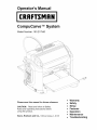
Operator's Manual
CRIIFTSM
CompuCarve
TM
System
Model Number: 183.217540
Please save this manual for future
reference.
CAUTION:
Read and follow all Safety
Rules and Operating Instructions before
using this product.
Sears,
Roebuck
and Co., Hoffman Estates, IL 60179
•
•
•
•
Warranty
Safety
Setup
Features
•
•
Operation
Maintenance
•
Troubleshooting
The CompuCarve TM System, with its computer-controlled
3D carving and
general woodworking
capabilities, is a revolutionary breakthrough
in
bench-top power tool design. This manual will explain the many features
of the CompuCarve
machine to help make creative carving operations
pleasant and rewarding.
Safety, performance,
and
design of the CompuCarve
operator's manual before
attention to the Rules For
the CompuCarve
System
it will provide many hours
dependability
have been given top priority in the
System. Read carefully through this entire
using the new CompuCarve
System. Pay close
Safe Operation and all Safety Alert Symbols.
If
is used properly and only for what it is intended,
of safe, reliable service.
For access to online information
visit http://www.carvewriqht.com.
WARNING
about the CarveWright
Design Software
or CAUTION:
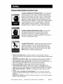
Look for this symbol to point out important
safety
It means attention -- Personal safety is involved!
precautions.
Look for this symbol to point out helpful information and hints
that will allow maximum efficiency and enjoyment of the
CompuCarve
system.
CRAFTSMAN
ONE-YEAR
LIMITED
WARRANTY
If this tool fails due to a defect in material or workmanship within one year or 200 hours of
use (whichever comes first) from the date of purchase, call 1-800-4-MY-HOME ® to
arrange for repair.
Consumable materials are not subject to warranty, and include, but are not limited to the
flex shaft, cutting/routing bits, grit surface drive belts, and lubricants.
Using the machine with unapproved cutting bits will void the warranty.
This warranty gives you specific legal rights, and you may also have other rights, which
vary from state to state.
Sears,
Roebuck
and Co., Hoffman Estates, IL 60179
Please keep the box and packaging from the CompuCarve
machine. This
box will be used for shipping in the event that the unit needs servicing.
Sears, Roebuck and Co.
CompuCarve
TM
System (Rev 1.6) 09/27/06
i
INTRODUCTION
TABLE
..................................................................................................
OF CONTENTS
SPECIFICATIONS
SAFETY
....................................................................................
...............................................................................................
.................................................................................................................
ELECTRICAL
GLOSSARY
CONNECTIONS
THE
.......................................................................
COMPUCARVE
MACHINE
II
3
4
...........................................................................................................
UNPACKING
I
7
8
...........................................
9
ITEMS INCLUDED WITH THE COIvIPUCARVE SYSTEM ...........................................
9
HARDWARE
FEATURES
OPERATION
......................................................................................................
USING
................................................................................
THE COMPUCARVE
CREATING
SYSTEM ....................................................................
PROJECTS WITH THE CARVEWRIGHT
NAVIGATING
THE MENUS
VIA THE KEYPAD
TM
SOFTWARE
..........................
AND LCD ......................................
Keypad Data EntlT .......................................................................................
BUILT-IN FUNCTIONS .........................................................................................
Rip or Cross
(_lt ...........................................................................................
12
15
15
15
16
17
17
18
Jointing and Squaring ...................................................................................
Bevel and Miter Cuts ....................................................................................
18
19
Routing an Edge ............................................................................................
Measuring
a Board .......................................................................................
19
20
20
CARVING
A PROJECT ..........................................................................................
Inserting
a Board
l/Vorkpieee
..........................................................................................
Preparation
.................................................................................
20
23
Jogging
the Cutting Truck ............................................................................
Auto Jigging Function ...................................................................................
25
25
Workpiece
26
CUTTING
Size Limitations
Bit Adapter
Assemb@
....................................................................................
PROPER BIT INSTALLATION
Approved
('ocking
Release
Installation
Bit Assembly
Removal
AND
GENERAL
................................................................................
Bits ................................................................................................
the Quick
Bit Assembly
CARE
...........................................................................
BITS ....................................................................................................
AND
TROUBLESHOOTING
Sears, Roebuck and Co.
..............................................................................
...................................................................................
MAINTENANCE
TIPS
Chuck ................................................................
..........................................................................
HELPFUL
REMINDERS
..........................................
.....................................................................................
CompuCarve
TM
System (Rev 1.6) 09/27/06
26
27
28
28
29
29
30
31
33
35
ii
Package Size .................................................
28.5" Long x 20.25" Wide x 18" Deep
Package Weight ............................................................................
78 Ibs (35.4 kg)
Machine Weight .............................................................................
70 Ibs (31.8 kg)
Cut Motor Speed (No Load) .................................................................
Cut Motor Horsepower (Peak) .....................................................................
Electrical Rating ...........................................................
20,000 rpm
1.0Hp
90-123VAC at 3.5 A, 60 HZ
Power Cord Length ....................................................................................
Movement Velocity:
Length Axis ........................................................................
6 feet
2" per second
Width Axis ........................................................................
12" per second
Up/down Axis ....................................................................
12" per second
Sears, Roebuck and Co.
CompuCarve
TM
System (Rev 1.6) 09/27/06
Page 3
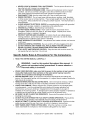
General Safety Rules For Power Tools
A CAUTION
ALWAYS WEAR EYE PROTECTION.
The operation
of any power tool can result in foreign objects being
thrown into the eyes, which can result in severe injury.
Before beginning tool operation, always wear safety
goggles or safety glasses with side shields and a fullface shield when needed. A Wide Vision Safety Mask is
recommended
for use over eyeglasses or standard
safety glasses with side shields. Always wear eye
protection that is marked to comply with ANSI Z87.1.
ACAUTION
ALWAYS WEAR EAR PROTECTION.
Power tools
can generate high levels of noise that will cause
permanent hearing loss. Before beginning tool
operation, always don hearing protection to minimize
the risk of damaging hearing.
A CAUTION
ALWAYS BE ALERT. Operating electrically powered
machinery poses a risk of serious physical injury to
hands and fingers. Always operate machinery with
ALL guards in place and in good working order. DO
NOT attempt to defeat safety guards!
•
KNOW THE POWER TOOL. Read the operator's manual carefully. Learn the
machine's applications and limitations as well as any specific potential hazards related
to this tool.
•
MAINTAIN TOOLS WITH CARE. Keep cutting tools sharp and clean for better and
safer performance. Follow instructions for lubricating and changing accessories.
USE THE RIGHT TOOL FOR THE JOB. Do not force the tool or attachment to do a
job for which it was not designed. Use it only the way it was intended.
DO NOT OVERREACH. Keep proper footing and balance at all times.
KEEP WORK AREA CLEAN. Cluttered work areas and workbenches invite
accidents. Keep floors clean and free of accumulated dust. DO NOT leave tools or
pieces of wood on top of the machine or on support extensions while it is in operation.
KEEP WORK AREA WELL LIGHTED. Good lighting promotes safety and good
output.
DO NOT USE IN DANGEROUS ENVIRONMENT.
Do not use power tools near
gasoline or other flammable liquids or explosive fumes. Do not use in damp or wet
conditions.
WEAR A DUST MASK to keep from inhaling fine particles. Use wood dust collection
systems whenever possible.
•
•
•
•
•
•
Sears, Roebuck and Co.
CompuCarve
TM
System (Rev 1.6) 09/27/06
Page 4
•
•
•
•
•
•
•
•
•
•
•
•
NEVER LEAVE A RUNNING TOOL UNATTENDED. Turn the power off and do not
leave the tool until it comes to a complete stop.
USE THE PROPER EXTENSION CORD. Make sure the extension cord is in good
condition. Use only a cord heavy enough to carry the current the product will draw
(see under Electrical Connections the proper gauges and lengths to use.)
DISCONNECT TOOL from the outlet when not in use or before servicing.
DRESS PROPERLY. Do not wear loose clothing, gloves, neckties, rings, bracelets,
or other jewelry near a running machine. They can get caught and draw the user into
moving parts. Wear protective hair covering to contain long hair. Non-slip footwear is
recommended.
GUARD AGAINST ELECTRICAL SHOCK by preventing body contact with grounded
surfaces such as pipes, radiators, or appliances while using the tool.
GROUND ALL TOOLS. (See Electrical Connections)
DO NOT ABUSE POWER CORD. Never yank the cord to disconnect it from
receptacle. Keep the cord from heat, oil, and sharp edges. Inspect power cords
regularly and repair or replace if damaged.
PROTECT VISITORS AND CHILDREN. All visitors should wear safety glasses,
hearing protection, and be kept a safe distance from work area. Do not let visitors
contact the tool or extension cord while it is operating.
MAKE WORKSHOP CHILDPROOF. Use padlocks and master switches, and remove
switch keys
AVOID ACCIDENTAL STARTING. Be sure switch is offwhen plugging in the tool.
DO NOT OPERATE ANY POWER TOOL WHILE UNDER THE INFLUENCE OF
DRUGS, ALCOHOL, OR ANY MEDICATION AFFECTING ALERTNESS.
STAY ALERT AND EXERCISE CONTROL. Stay alert and use common sense. Do
not operate the tool when tired. Do not rush.
Specific
•
Safety Rules & Precautions
For The CompuCarve.
READ THIS ENTIRE MANUAL CAREFULLY
WARNING:
Look for this symbol throughout
this manual.
points out important
safety precautions.
It means attention
Personal safety is involved!
•
•
•
•
•
•
•
•
It
--
WHILE USING MACHINE, make sure that the power to the machine is kept constant.
Using other high power draw machines on the same power leg may cause the
machine to lose position and damage the workpiece.
BEFORE MAKING A CUT, be sure that all mechanical adjustments and settings are
secure. Until thoroughly familiar with the operation, it is a good idea to create a checklist to
help ensure all are secure.
REMOVE WRENCHES AND ADJUSTING KEYS. Get in the habit of checking - before
turning on the tool - that any hex keys or adjusting wrenches are removed from tool.
CHECK FOR DAMAGE. Before using the tool, routinely check for any damaged parts,
including guards. Look for anything that could interfere with proper operation and
performance, such as any binding or misalignment of moving parts or any sign of
instability in the carving system. A damaged part must be properly repaired or replaced by
a qualified service technician at a repair center to avoid risk of personal injury.
BE SURE THE BIT CLEARS THE WORKPIECE. Never start the system with the bit
touching the work piece.
DO NOT HOLD OR STRESS THE FLEX SHAFT DURING OPERATION. Placing stress
on the shaft during operation will accelerate wear and cause premature failure.
NEVER ATTEMPT TO DEFEAT SAFTY DEVICES OR INTERLOCKS. Guards and other
safety devices protect the user from injury; do not try to bypass or remove them.
KEEP HANDS AWAY FROM CUTTING AREA. When the machine is running, never
reach underneath the workpiece or into the blade-cutting path for any reason.
Sears, Roebuck and Co.
CompuCarve
TM
System (Rev 1.6) 09/27/06
Page 5
•
•
•
•
•
•
•
•
•
•
•
•
•
•
•
•
•
•
DO NOT PLACE HANDS ON THE GRIT SURFACE DRIVE BELTS DURING
OPERATION. Belts in motion could drag a hand into the machine and cause injury.
AVOID AWKWARD OPERATIONS AND HAND POSITIONS where a sudden slip could
cause hands to move into the cutting area.
NEVER OPERATE THE MACHINE WITHOUT THE MUFFLER BAG IN PLACE. The bag
captures dust and debris from machining operations.
NEVER LOOK INTO THE VACUUM OUTLET DURING MACHINE OPERATION.
Machining debris could be thrown out at high speed and cause eye injury.
TURN OFF THE SYSTEM IF A STRANGE NOISE OR HEAVY VIBRATION OCCURS.
Immediately turn off the system. Then locate and correct the source of the problem before
restarting.
USE A SUPPORT FOR LONG WORKPIECES. To minimize the risk of over stressing the
machine, use a sturdy "outrigger" support when carving long workpieces more than 36
inches in length. Never substitute a person for a proper support.
USE RECOMMENDED ACCESSORIES.
Using improper accessories may risk injury.
Consult the accessories section for recommended accessories.
USE ONLY APPROVED CUTTING BITS to ensure quality and to avoid equipment
damage or injury.
KEEP BITS CLEAN AND SHARP. Sharp bits minimize workpiece burning, poor cut
quality, and stress to the system. Keep bits free of rust, grease, and pitch.
USE GLOVES TO HANDLE HOT CUTTING BITS. Recently used cutting bits are hot,
and all bits have sharp edges; gloves will help prevent cuts and burns.
USE ONLY ORIGINAL REPLACEMENT PARTS. Repairs using other than original
replacement parts may create a hazard as well as damage to the machine. To ensure
proper repair using original replacement parts, a qualified service technician at a Sears
service center should make all repairs, whether electrical or mechanical.
DO NOT USE THE TOOL IF THE POWER SWITCH DOES NOT TURN IT ON AND OFF.
Have defective switches replaced by a Sears service center.
CUT ONLY WOOD, PLASTIC OR WOOD-LIKE MATERIALS. Do not cut metal.
NEVER cut more than one piece at a time.
DO NOT STACK more than one workpiece in the CompuCarve at a time.
BE SURE THE WORKPIECE PATH IS FREE OF NAILS. Inspect for, and remove all
nails, staples, and protruding features from the lumber before cutting.
KEEP TOOL DRY, CLEAN, AND FREE FROM OIL AND GREASE. Always use a clean
cloth when cleaning. Never use brake fluids, gasoline, petroleum-based products, or any
solvents to clean the system.
DO NOT STAND ON TOOL. Serious injury can occur if tool is tipped or if the cutting tool
is unintentionally contacted.
WARNING:
Operation of this tool should not be attempted until all
instructions, safety rules, etc. contained in this manual have been read thoroughly and
understood completely. Failure to do so can result in accidents involving fire, electric
shock, or serious personal injury. Save the operator's manual and review it frequently for
continuing safe operation and for instructing others who may use this tool.
WARNING!
Some dust created by power sanding, cutting, and drilling
contains chemicals known to cause cancer, birth defects, allergic reactions, or
reproductive damage. Some examples of these chemicals are:
•
Lead from lead-based paints
•
Arsenic, copper, and chromium from chemically treated lumber
•
Wood resin
•
Plastic solvents
•
Silica Dust
Sears, Roebuck and Co.
CompuCarve
TM
System (Rev 1.6) 09/27/06
Page 6
To reduce exposure to these chemicals:
•
Work in a well ventilated area
•
•
Work with approved safety equipment, such as dust masks that are specially
designed to filter out microscopic particles
Keep the machine and work area clean
IMPORTANT
NOTE:
Servicing requires much care and specialized
knowledge of the system and should be performed only by a qualified service technician.
For service, return the machine to the nearest repair center in the original packaging.
POWER SUPPLY
The CompuCarve woodworking machine is controlled by precision electronics, tt should
be connected only to a power supply that is 120 volts nominal, 60 Hz, AC (normal
household outlet). It should not be connected to a 240-volt power supply. This tool will
not operate on direct current (DC). If the machine does not operate when plugged into
an outlet, check to see that the fuse or circuit breaker for the outlet is not open and that
the outlet has power available.
EXTENSION
CORDS
When using a power tool at an extended distance from the power source, use an
extension cord heavy enough to carry the current that the tool will draw. An undersized
extension cord will cause a drop in line voltage, resulting in a loss of power and causing
potential damage to the machine. Use the chart provided below to determine the
minimum wire size required in an extension cord. Only jacketed cords listed by
Underwriter's Laboratories (UL) should be used.
Length of Extension
Cord vs. Wire Size (American
Wire Gage - AWG)
Up to 10 feet - 18 AWG minimum
10 to 50 feet - 14 AWG minimum
Over 50 feet - not recommended
When working with the tool outdoors, use an extension cord that is designed for outside
use (This is indicated by the letters WA on the power cord's outer jacket). Before using
an extension cord, inspect it for loose or exposed wires and cut or worn insulation.
Sears, Roebuck and Co.
CompuCarve
TM
System (Rev 1.6) 09/27/06
Page 7
Bevel Cut
A cut made across a workpiece
the table surface.
that results in an angle other than 90 ° to
Cross Cut
A cutting operation
across the grain or width of the workpiece.
Head Screw
The threaded shaft on each side of the machine by which the head is
raised and lowered when activated by the head crank.
Joint or Jointing
A trim cut parallel to the grain of the wood on the edges of a board to
create 90-degree angle with the top and bottom surface. A joint will create
a smooth and, most important, straight edge. Often used in preparation
for a glue joint to attach the board to another piece of wood.
LCD
Liquid Crystal Display - The two-line
text display found above the keypad.
Miter Cut
A vertical
cut made at any angle other than 0 ° across the workpiece.
Molding
A shaping
cut that gives a varied profile to the workpiece.
Pitch
A sticky, sap-based
substance
found in some woods.
Rip Cut
A cut made parallel to the grain or length of the workpiece.
Rout
To hollow, scoop or carve out.
Snipe
An unwanted depression formed near the end of a workpiece caused by
the uneven transition of the workpiece from one support surface to
another. Snipe can be minimized by ensuring that auxiliary outfeed
supports are even with machine support surfaces. The free end of the
workpiece should also be well supported so that its weight does not place
lifting pressure at the end of the workpiece being carved.
Squaring Cut
A smoothing trim cut across the grain of the wood on the end of a board
to create 90-degree angles with the top, bottom, and side edges.
Vector
Cut
A cutting operation that is composed of a group of strokes from one point
to another. These can be lines, circles, splines or any other number of
geometric elements.
Workpiece
The item on which the cutting operation is being performed.
The surfaces
of a workpiece are commonly referred to as faces, ends, and edges.
Sears, Roebuck and Co.
CompuCarve
TM
System (Rev 1.6) 09/27/06
Page 8
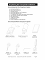
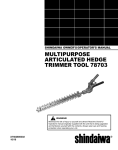
Items included with the CompuCarve
A)
B)
C)
D)
E)
F)
G)
H)
I)
J)
K)
System
CompuCarve
Machine
CarveWright Software CD
Operation Manual
CarveWright Memory Card Programmer
CarveWright Memory Card
1/16" Diameter Tip Tapered Carving Bit with Bit Adapter
1/8" Diameter Cutting Bit with Bit Adapter
3/32" Allen Wrench
Muffler Dust Collector
Bit removal Tool
Crank Handle Ball and Shoulder Bolt
Items Included
With the CompuCarve
System
\,i?,,
//
/iY //
FIGURE
MEMORY
1:
FIGURE2:
CARVEWRIGHT
CARD PROGRAMMER
MUFFLERAND
COLLECTOR
DUST
BAG
FIGURE 3:
CARVEWRIGHT
MEMORY
CARD
/
FIGURE4: 1/8"
CUTTING
BIT WITH
ADAPTER
FIGURE 5"
CARVING
FIGURE 6: 3/32"
ALLEN WRENCH
1/16"
BIT WITH
FIGURE7:
REMOVAL
BIT
TOOL
ADAPTER
Sears, Roebuck and Co.
CompuCarve
TM
System (Rev 1.6) 09/27/06
Page 9
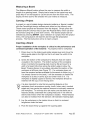
Unpacking
and Setting Up the CompuCarve
System
1. Remove the top packaging foam: After opening the shipping box,
carefully remove the top molded foam packing from the machine.
Located in the top tray are items B through K listed above.
2. Remove the machine from box: With a helper, lift out the machine
and place it on a sturdy table or bench. Fold down the Outfeed Support
Tables. Remove the plastic film covering the top clear safety cover.
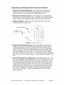
3. Attach the handle: Attach the crank handle ball to the crank lever
using the supplied shoulder bolt.
Crank Handle Ball
Handle
Shoulder Bolt
FIGURE 8: ATTACHING
THE HANDLE
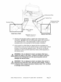
4. Prepare the flexshaft
assembly:
Remove the plastic wrapping and
rubber band from the end of the flexshaft assembly. Gently pull the
protruding flexshaft core (with squared end) out of the sheath several
inches. Push the core back into the sheath and make sure that it slips
into, and engages, the cutting motor. Turn the core with your fingers
and feel for resistance of the motor. If the shaft spins without resistance
push the core in as you slowly rotate it. You should feel it engage in the
slot.
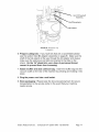
5. Insert the flexshaft
into cutting head: Looking through the slot in the
top cover, locate the shaft receptacle in the top of the cutting head. The
end of the flexshaft assembly is held in place with a ball detent. Inside
the receptacle there is a square recess that mates with the exposed
square end of the flexshaft cable. Turn the chuck on the bottom of the
cutting head (open the safety cover for access) until the square cable
end can be inserted into the recess. Press the flex shaft all the way
down into its receptacle.
A click will be heard and felt as the shaft
snaps into place.
Sears, Roebuck and Co.
CompuCarve
TM
System (Rev 1.6) 09/27/06
Page 10
End Of Flexshaft
Assembly
Shaft Receptacle
Ball Detent
FIGURE 9"
INSERTING THE
FLEXSHAFT
6. Prepare cutting bits: If you have bits that are un-assembled
please
see the section titled Bit Adapter Assembly on page 26. Make sure the
shaft of the bits extend all the way through the bit adaptor and always
make sure the setscrews are tight and oriented to the flats on the
shank. On the 1/4"shank bits, use a drop of permanent
thread
cement to prevent them from loosening.
7. Attach muffler and dust collector
bag:
vacuum outlet on the rear of the machine
place.
8. Plug the power
cord
Insert the muffler bag into the
by pressing and twisting it into
into a wall outlet.
9. Store packaging:
Please keep the box and packing foam for secure
transportation to the service center in the event that your machine
needs service.
Sears, Roebuck and Co.
CompuCarve
TM
System (Rev 1.6) 09/27/06
Page 11
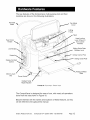
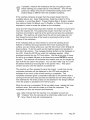
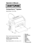
The key features of the CompuCarve multi-purpose tool and their
locations are shown in the following illustrations.
Flexshaft
Cable
Top Safety
Cover
Cutting
Trucks
Head
Head Locking
Lever (Shown in
Non-Locked
Position)
Head Crank
Handle
_._
LCD Display
Sliding Guide Plate
Release Lever
Keypad
Vertical Corner Post
Sliding Guide Plate
Display Contrast
Control
Memory Card
Slot
• Folding Outfeed
Table
Power Switch
Outfeed Table
Height Adjuster
FIGURE
10:
FEATURES
- FRONT VIEW
The CompuCarve
is designed for ease of use, with nearly all operations
done from the side shown in Figure 10.
Become familiar with the names and locations
will be referred to throughout this manual.
Sears, Roebuck and Co.
CompuCarve
TM
of these features,
System (Rev 1.6) 09/27/06
as they
Page 12
HARDWARE
FEATURES
(cont.)
Air Intake
,,Cutting Motor
Squaring Plate
Muffler and Dust
Collector Bag
Sliding Guide
Plate
Folding Outfeed
Table (rear)
Outfeed Table
Height Adjustment
FIGURE11 :
FEATURES
Top Compression
Roll e rs
- REAR VIEW
'_"_:"_
FIGURE12:
(OUTFEED
FEATURES,
TABLE
VIEW
FROM BELOW
NOT SHOWN FOR CLARITY)
Sensor
Sears, Roebuck and Co.
CompuCarve
TM
System (Rev 1.6) 09/27/06
Page 13
HARDWARE
FEATURES
(cont.)
Vertical Moving Truck
(Z-Truck)
Y-Truck Guide
Horizontal Moving Truck
(Y-Truck)
Z-Truck Guide Rails
FIGURE13:
CUTTING
HEAD ASSEMBLY
Overhead View of Machine
(with workpiece)
1
Z-Axis is up/down
Workpiec_
Far-side
1
This corner (near left) of
the workpiece is the
coordinate origin for all
board measurements
FIGURE 14: DIRECTIONAL CONVENTIONS
Sears, Roebuck and Co.
CompuCarve
TM
System (Rev 1.6) 09/27/06
Page 14
Using the CompuCarve
System
Before the CompuCarve
can begin to function, the CarveWright memory
card must be installed. With the power off, push the memory card gently
into the memory card slot until it stops, making sure the label is up.
WARNING:
Never remove the memory card from the machine
while it is on. Doing so can result in damage to the workpiece.
At any point during operation the CompuCarve
machine can be
stopped by pressing the STOP key or by lifting the cover. If desired
the machine can be restarted by closing the cover and pressing
ENTER. The machine will resume cutting at the point where it was
stopped. If you press the stop button a second time the project will
be aborted so be careful when restarting your project.
Once the CarveWright memory card is installed, the machine can be
turned on with the power switch. Look at the LCD display, and rotate the
contrast control knob (located directly under the keypad) until the display
is readable from a comfortable angle.
The CompuCarve
may be used in two complementary
ways. First, and
most powerfully, the CompuCarve
can carve intricate patterns and
designs created through the CarveWright design software running on a
computer.
Second, there are built-in woodworking
functions on board the
machine including:
•
•
Rip Cuts
Cross Cuts
•
•
•
•
Edge Jointing
End Squaring
Miter Cuts
Bevel Cuts
•
Edge Routing
These built-in functions are generally used to prepare a board for carving,
but they can be used to dress up a board if desired. (See section titled
Built-In Functions below.)
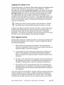
Creating
Projects with the CarveWright
TM
Software
Discussion of the usage of the CarveWright design software is beyond the
scope of this manual and is covered separately.
Please refer to the
CarveWright software user's manual on the included CD for further
information.
It is advisable to have a supply of suitably sized scrap wood on
hand for trial cuts. Very often it is desirable to tweak details in a
design before doing a final carving.
Sears, Roebuck and Co.
CompuCarve
TM
System (Rev 1.6) 09/27/06
Page 15
Navigating
the Menus Via the Keypad and LCD
For input and display of information the CompuCarve
machine employs a
tactile keypad and LCD display. ALL operations require the user to input
information at the actual machine location via the keypad (as opposed to
information input and passed through the design software).
The amount
of information needed is dependent on the operation requested.
The
layout of the keypad is shown below.
FIGURE15:
COMPUCARVE
INPUT KEYPAD
The CompuCarve's
LCD display consists of two lines. Typically, the
display will print a menu name or a prompt on the top line and a related
menu option on the second line.
FIGURE16: COMPUCARVE
LCD DISPLAY
The LCD display's contrast may be adjusted with the small knob
located directly below the keypad. To turn it, place a thumb on the
knob's surface and press in while twisting.
Navigating the menu structure is usually done by browsing through the
menu structure.
Alternatively the shortcut keys on the keypad can be
used if the user is familiar with the options. Browsing
uses three buttons
on the keypad: up arrow, down arrow, and the ENTER key. As described
previously, when a menu is displayed, the menu name will be on the top
line and the current menu option will be displayed on the bottom line of the
display. To browse the other menu options simply press the down arrow
on the keypad to move to the next option. To return to a previous option,
press the up-arrow. When the bottom of a menu options list is reached,
pressing the down key will wrap back to the top of the menu.
Pressing the STOP button while in the menu structure will
automatically
return the user to the previous menu prompt.
After an option is selected within a menu the machine may offer further
choices to be selected, or it may require additional data about the board
and the type of cut desired. This may require a keypad entry.
Sears, Roebuck and Co.
CompuCarve
TM
System (Rev 1.6) 09/27/06
Page 16
Keypad Data Entry
When a menu option asks for numerical data, such as length or depth
dimensions, the keypad is used to enter the data. When fractional values
are involved, data may be entered as either decimals or fractions.
Decimals are the simplest. To enter a decimal simply type the whole
number then the decimal point (down arrow key) followed by the decimal
part (i.e. 12.345).
Fractions are entered simply by placing the '/' (located on the up arrow
key) between the numerator and denominator.
To enter a pure fraction
such as 1/2, simply type the numerator (in this case '1') then '/' (up arrow
key) then the denominator (in this case '2'). A mixed fraction (i.e. 1 3/16)
is not much harder: Simply enter the whole number followed by a space
(right arrow) and then the fraction entered as above. To go back or
correct an incorrectly entered number use the left arrow.
Shortcut keys can be a faster way to get around the menus once they
are learned. Shortcut keys are used primarily to access the built-in
functions.
The shortcuts options are printed below the numbers on the
keypad (see Figure 15) and include the following:
Projects
Cut
Rout
Joint
Miter
Acssory
Measure
Repeat
Options
Key will
Key will
Key will
Key will
Key will
Key will
Key will
Key will
without
Key will
initiate the Projects menu.
initiate the Cross Cut and Rip Cut menu.
initiate the Edge Routing menu.
initiate the Squaring and Jointing menu.
initiate the Bevel and Miter Cut menu.
access a menu of any add-on accessories.
allow user to measure width or length of piece.
allow user to repeat the previous operation
having to go through all of the setup steps.
allow access to machine settings and info.
Built-In Functions
The CompuCarve
machine is capable of performing most of the basic
woodworking
operations normally done on conventional equipment, such
as a table saw, a jointer, a miter saw, a shaper, or a router. For large
projects, the user who has access to the latter tools can determine which
method is most advantageous
in any given situation. However, for smaller
projects the ease of use and the precision of cuts clearly make the
CompuCarve
machine the preferred choice. Frequently it will be desirable
- and in some cases necessary - to dress a board before carving. The
built-in functions make it possible to easily perform this task with only one
machine. To access the CompuCarve's
various built-in functions, a menu
style interface has been provided that uses the keypad and LCD display.
Shortcuts to these functions are conveniently
located on the CompuCarve
keypad. These shortcuts allow the built-in functions to be performed
without the use of the CompuCarve
design software. The following is a
brief description of each of the built-in functions:
Sears, Roebuck and Co.
CompuCarve
TM
System (Rev 1.6) 09/27/06
Page 17
_
and
ARNING:
output quality,
From the
it is
standpoint
important of
to safety,
follow machine
all instructions
longevity,
concerning the proper bit to be used for each built-in function.
For approved router bits, visit the CarveWright website.
Rip or Cross Cut
This function is provided to allow a board to be sized by width and/or
length. A Rip cut (along the grain or long axis) will size a board to the
desired width; a cross cut (across the grain or narrow axis) will size a
board to the desired length. Once Cross or Rip is selected from the Cross
or Rip Cut menu, prompts are made for the desired length or width of the
finished board. A Rip Cut will ALWAYS
be performed to the far side of
the board and a Cross Cut will ALWAYS be performed to the right end of
the board as explained in Figure 14. Finally there will be a prompt to Load
the 1/8" Cutting Bit (included).
If many pieces of the same width or length are desired, simply raise
the head, remove all material from the machine, load a new the
board, set the sliding guide plate, lower the head, and press
Repeat.
Many times it is useful to run a jointing
up the cut edge.
operation
after a rip to clean
If you intend to joint the board after ripping it, cut the material
slightly wider to allow for the jointing passes that remove ~1/64" on
each pass.
Jointing and Squaring
Jointing and squaring operations, which are often difficult on smaller
boards, can be done quickly and with extreme precision using this built-in
function.
Squaring ensures that the corner angle of the board surface is a
true 90 degrees.
Jointing
ensures that the edge of the board is a uniform
90 degrees to its surface. Squaring is always done on the board end. For
the Joint or Square function the user will be prompted to select either
Square or Joint. If Square is selected the machine will ALWAYS perform
the operation to the left end of the board as explained in Figure 14. If
Joint is selected the machine will ALWAYS perform the joint to the far
edge of the board. After selecting the desired option the LCD will prompt
the user to Load a 3/8" Jointing bit (not included).
Because the software limits the depth of the joint or square to 1/64"
(.015") the Repeat shortcut key is often used to quickly take
additional passes. To repeat a jointing pass simply raise the head,
re-center the board in the machine, re-set the sliding guide plate,
lower the head, and press Repeat.
Sears, Roebuck and Co.
CompuCarve
TM
System (Rev 1.6) 09/27/06
Page 18
If it is desired to square both ends, or joint both sides, of a board,
simply reverse the board in the machine and repeat the operation.
If there is a significant crown to the board, place the highest point of
the crown under the cutting head. This will allow the machine to
measure the highest point of the crown and will prevent the
machine from taking and excessive cut. Use the Repeat shortcut
key as many times as necessary
_
to eliminate
the crown.
ARNING:
Use only a 3/8" straight bit for jointing
Any other bit can cause damage to the workpiece
and can result in serious injury.
or squaring.
or machine
Bevel and Miter Cuts
Bevel cuts are cut at an angle across the thickness of the workpiece.
A
typical bevel cut application would be seen in making small boxes where
the corners are formed by two 45-degree bevel cuts. Miter cuts are cut at
an angle across the width of a workpiece.
A typical application would be a
picture frame. Once the Miter shortcut key is pressed user will be
prompted to choose either the Bevel or Miter type of cut and then the
desired angle. For bevel cuts there will also be the option to Cross or Rip
depending on what edge will be beveled. A Cross bevel will ALWAYS be
applied to the left end of the board and a Rip bevel will ALWAYS be
applied to the far side of the board as explained in Figure 14. Finally,
there will be a prompt to insert a 1/4" Ballnose bit (not included' for bevel
cuts or a 1/8" Cutting bit (included) for a miter cut.
To repeat the last Bevel or Miter cut to multiple boards, s_mply raise
the head, remove the previous board from the machine, load a new
the board, set the sliding guide plate, lower the head, and press
Repeat.
Routing an Edge
The Edge Rout function allows the user to rout the edges of a rectangular
board with a shaped bit. Various decorative edge effects can be
achieved, depending on the available bit selection. The user will be
prompted to select the edges to rout. Choices include: an End, an Edge,
or All Edges. If Edge is selected the rout will ALWAYS be applied to the
far side of the board and if End is selected the rout will ALWAYS be
applied to the left end of the board as explained in Figure 14. Finally,
there will be a prompt to select a bit from the selection menu. After the
first rout operation the LCD will ask if the depth is OK.
To repeat the last Edge Rout to multiple boards, simply raise the
head, remove the previous board from the machine, load a new the
board, set the sliding guide plate, lower the head, and press
Repeat.
Sears, Roebuck and Co.
CompuCarve
TM
System (Rev 1.6) 09/27/06
Page 19
Measuring
a Board
The Measure Board
length of an existing
press Key #7 on the
display will then ask
Carving
function allows the user to measure the width or
board. Simply load a board in the typical way and
keypad or use the arrows from the main menu. The
for the direction the user wishes to measure.
a Project
A project is a set of related design elements (patterns or figures) created
with the CarveWright design software and stored on the memory card.
These stored projects are accessed from the keypad. Simply press the
Projects (Key #1) shortcut key to open the Projects Menu which can then
be browsed using the up and down arrows. The desired project can be
selected by pressing ENTER. Upon selection of a project from the project
menu, the CompuCarve will lead the user through the preparation
process. The first instruction will be to insert a board.
Inserting
a Board
Proper installation
of the workpiece is critical to the performance
and
continued operation of the machine. To properly insert a workpiece:
1. Press down on the sliding guide plate release lever and move the
sliding guide plate to the right so that it will clear the width of the
workpiece.
,
Check the bottom of the workpiece for features that will make it
unusable in the machine. The bottom surface of the workpiece
where it contacts the squaring plate must be flat and level for a
width of at least 3/8 inches along the bottom edge to allow the
Board Tracking Sensor to accurately calculate the position of the
workpiece at all times (see Figure 17). If a workpiece does not
have the required surface available for the sensor to follow (e.g., if
it is already carved on the back), it will be necessary to fasten the
workpiece to a sled or carrier jig to do further work on it. If a
workpiece is slightly cupped or bowed, the workpiece should be
inserted with the cup or bow facing down.
It is also important to note that any existing features on the
workpiece (such as previous carving, knots, holes, paint, rounded
edges etc) may cause the machine sensors to incorrectly measure
the workpiece.
To minimize this risk make sure that there are no
features directly underneath the cutting head and in line with the
side-to-side motion when the workpiece is loaded. These features
can also be masked from the sensors with standard masking tape.
3. Lay the workpiece on the traction drive so that it is centered
lengthwise under the head.
4. Push the board firmly up against the squaring
Sears, Roebuck and Co.
CompuCarve
TM
plate.
System (Rev 1.6) 09/27/06
Page 20
Sliding Guide Plate
Traction Drive
Sliding Guide Plate
Release Lever
Squaring Plate,
Board Tracking
Sensor
Board Sensor Detail
FIGURE17:
INSERTION
,
,
WORKPIECE
Release Lever Detail
DETAILS
Gently push the sliding plate up against the inside edge of the
workpiece.
DO NOT push the sliding plate against the workpiece
with significant force. The sliding plate is used to guide the
workpiece and is not intended to lock the piece in position.
At this point it is critical that you assure that the workpiece can
travel freely in and out of the machine along its entire length without
binding or encountering
significant drag. Do this by moving the
workpiece in and out of the machine by hand, while laying flat on
the traction drive.
WARNING:
Do not attempt to load a workpiece that has a
significant taper to the sides. A tapered workpiece will bind
between the sliding plate and the squaring plate and will
damage the traction drive.
WARNING:
Do not attempt to load a workpiece that varies in
thickness by more than 1/16" along its entire length. Using a
workpiece with a larger thickness variation than 1'16" can lead
to damage to the machine.
Sears, Roebuck and Co.
CompuCarve
TM
System (Rev 1.6) 09/27/06
Page 21
,
Next, lower the head by turning the head crank handle counterclockwise until the clutch clicks several times (at least 5 clicks
recommended).
The clutch is intended to load the board against the traction drive
with consistent force. In certain cases the machine can sense if the
workpiece is not loaded enough and repeatably display "Please
Load Board" on the LCD. Most often this decreased loading is
caused by insufficient lubrication of the four vertical corner posts or
the two vertical leadscrews.
Please see the Checking the Head
Pressure in the troubleshooting
section for the proper lubrication
procedure.
,
The head-locking
lever is then rotated outward into the locked
position. The workpiece is now secure and ready to be carved.
9. Make sure that the top safety cover is closed before proceeding.
Locking Lever
In Locked Position
....
FIGURE
18:
LOCKING
LEVER CONFIGURATION
Make sure that the locking lever is released after finishing carving.
If the locking lever is NOT released the head will not be able to
move up and down.
WARNING:
Failure to correctly load the clutch by ratcheting
at least five times may result in diminished carving quality.
Sears, Roebuck and Co.
CompuCarve
TM
System (Rev 1.6) 09/27/06
it
Page 22
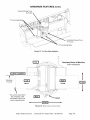
Workpiece
Preparation
Before carving can begin a number
operations must be navigated.
of menu prompts and machine
The machine will ask if the workpiece is to Stay Under Rollers. Keeping
the workpiece under the top rollers is a way of avoiding undesirable snipe
in the cut and maintaining contact with the Board Tracking Sensor at all
times. It is recommended
that this option is used when under the
following circumstances:
• Best carving quality is desired
• The project has routing to or near the ends of the board.
• The project has cutting to or near the ends of the board.
• The project is longer than 20 inches and there is carving to the
ends of the board.
If YES to Stay Under Rollers is selected the machine will automatically
assure that there is 3 1/2" extra length on either side of the project. In
many cases you will have to account for this extra length by inserting a
longer workpiece then is shown in the design software. The other option
is to have the project scaled to the board size while accounting for the
length needed to keep under rollers. Most times this will not produce the
desired effect.
i iWorkpiece
II
Workpiece size as
shown in the design
software
FIGURE19:
A
GRAPHIC
DESCRIPTION
ROLLER OPTION
(AREAS A&B
shown in the design
software
B
OF STAY UNDER
ADDED)
The machine will then measure the workpiece.
If the size of the inserted
workpiece does not match the size of the designed project then the
machine will prompt for additional information.
The machine will ask
different questions based on if the workpiece installed in the machine is
larger or smaller than the project designed in the software.
If the
workpiece is smaller than the designed project, then the options are:
Scale the project to fit the workpiece or Load New Board. If the Scale
option is selected then options Center On Board, Jog To Position, or Place
On Comer are displayed in order to locate the project on the workpiece.
WARNING:
Be very careful when scaling down a project at the
machine.
The machine will scale the entire project to the
largest size that will fit the inserted workpiece while
maintaining the overall aspect ratio of height to width. It will
not change the aspect ratio to fit that of the inserted
workpiece.
Scaling down can also lead to undesirable
thinning of carved elements that may lead to chip out.
Sears, Roebuck and Co.
CompuCarve
TM
System (Rev 1.6) 09/27/06
Page 23
If possible, measure the workpiece that you are going to carve
before starting your project layout in the software. This will help
guide your design and prevent unintended scaling issues if the
project design is different then the available workpiece.
If the inserted workpiece is larger than the project design then the
available options are: Keep Original Size, Scale the project to fit the
workpiece, or Load New Board. If Keep Original Size or Scale is selected
then options Center On Board, Jog To Position, or Place On Comer are
displayed in order to locate the project on the workpiece.
Once all of the required data has been entered, the machine will prompt to
insert the required bit. For projects that require more than one bit, the
machine will prompt for each bit at this point and will store the calibration
settings. The machine will locate the bit tip with its touch plate and will
then locate the top surface of the board by touching the bit tip to the
surface of the workpiece.
If the workpiece that you have chosen to carve has existing carved
features or defects that would prevent the bit from touching the top
surface, you can choose where you want the bit to touch when finding the
board surface. To do this watch as the machine begins the operation to
find the bit tip position. The message Finding Surface will be displayed on
the LCD. Press the STOP key when this message appears.
When
prompted choose the Jog To Touch option. Use the arrow keys to move
the bit tip to a suitable flat spot on the board and press ENTER to record
position. The machine will remember this location and use it to locate the
tips of all the bits used in the project. You can also make "Jog To Touch"
the default method by choosing this in the options menu. This option
remains set only until the machine is powered off.
The machine will then proceed to carve the project. A real time carving
completion estimator will be displayed on the LCD and provides an
estimate of how much of the current carving is completed.
This
completion estimator gives a completion estimate for the element that is
carving at the time and does provide and estimate for the entire project. A
time estimate for the entire project can be obtained in the design software
when the project is uploaded to the memory card.
When the carving is completed, lift the top safety cover, release the head
Iockdown lever, and crank the head up to free the workpiece.
The
workpiece can then be removed and examined.
After removal from the machine, it is advisable to brush any
"whiskers" from the carving with a small brass utility brush, and to
blow it free of dust with compressed air.
Sears, Roebuck and Co.
CompuCarve
TM
System (Rev 1.6) 09/27/06
Page 24
Jogging the Cutting Truck
As described above, the machine offers several options for positioning the
carving on the workpiece, one of which is "Jog to Position."
This is
accomplished
using the up and down arrows on the keypad to move the
cutting truck across the width of the workpiece (near to far), and the left
and right arrows will move the workpiece along its length (left or right).
This option allows the user to place a carving at some location on a
workpiece other than center or left corner. This is especially useful if one
wishes to avoid a blemish in the wood or to incorporate some feature like
a knot into the carving. Figure 14 illustrates the directional conventions
used with CompuCarve.
Holding an arrow key down results in a fast movement.
Precise
final positioning is accomplished
using short bumps on the key.
In addition to jogging to position with the arrow keys, if any number key is
pressed while in jog mode, the machine will enter coordinate mode. In
coordinate mode, there will be a prompt for the X and Y coordinate
destination.
The machine coordinates will be the distances from the nearleft hand corner of the workpiece
(when facing the keypad).
Auto Jigging Function
Occasionally
a project will contain carvings or routs that can interfere with
the mechanical operation of the machine. Types of interference fall into
the following categories:
1. Wide vertical cuts across the top surface if the workpiece can
cause the compression rollers to fall during a project, affecting
machine's ability to move the workpiece.
,
the
Cuts through the board along the top edge of the workpiece (as
viewed in the software) can interfere with the Board Tracking
Sensor and affect the machine's ability to track the position of the
workpiece.
3. Carvings on the rear face of the workpiece and near the bottom of
the workpiece (as viewed in the software) can also interfere with
the Board Tracking Sensor when the workpiece is flipped over.
,
Cuts with the Cut Tool along the right side of the workpiece can
potentially break the cutting bit if the workpiece leaves the Board
Tracking Sensor and the machine loses high-precision tracking of
the workpiece.
In the event that the CarveWright TM designer software recognizes that any
of these conditions are met within a project, the software will display a
warning when the project is uploaded to the memory card. The specific
conditions will be listed, and the user may choose to ignore the warning
Sears, Roebuck and Co.
CompuCarve
TM
System (Rev 1.6) 09/27/06
Page 25
(which may result in undesired machine operation), manually jig the
project, or allow the machine to automatically jig the project (Auto-Jig).
When Auto-Jig is selected, the machine will prompt for a workpiece that is
slightly wider or longer than the project's dimensions in order to prevent
interference with the machine's mechanics. When the project is complete
the machine can cut off the extra material if desired.
Workpiece
Size Limitations
Small Workpiece
The minimum acceptable size of a workpiece that can be inserted into the
CompuCarve
is 2.5 inches wide x 0.25 inches thick x 7 inches long. It will
be necessary to mount the workpiece onto a jig if any single dimension is
smaller than the stated minimums.
Large Workpiece
The maximum size of a workpiece is limited only by the physical size of
the CompuCarve
machine, and is 14.5 inches wide and 5 inches high.
There is no physical limit to workpiece length, but any workpiece over 3
feet long will require that additional stand-alone outfeed support rollers be
used. The support rollers should be adjusted properly to avoid letting the
workpiece sag or rise, as any transition going on and off the rollers will be
reflected in the carved surface in a manner similar to a snipe.
The weight of
of the carving
than 20 Ibs in
will accelerate
Cutting
the workpiece is also a limiting factor, related to both quality
and longevity of the drive mechanism.
Any workpiece more
weight places increased stress on the drive mechanism and
wear of the system.
Bits
The CompuCarve
comes equipped with two bits mounted in bit adapters.
These are the 1/16" tip diameter carving bit and a 1/8" cut-off bit.
Additional bits and bit adapters, made to the CompuCarve
specifications,
are available through the Sears web site.
WARNING:
Piloted bits can NOT be used in the machine.
WARNING:
While any 1/4" or 1/2" shank router bit can
physically be inserted into the bit holder of the CompuCarve,
users are strongly advised not to attempt this. The machine is
calibrated to work within certain specifications,
and if these
specifications
are not met the results will be unpredictable
at
best. It is also possible to overstress the machine with
nonstandard
bits, which could be both damaging and
hazardous.
Sears, Roebuck and Co.
CompuCarve
TM
System (Rev 1.6) 09/27/06
Page 26
Bit Adapter Assembly
The CompuCarve
utilizes a patented quick release chuck system to make
changing bits fast and easy. To use this system the bits must first be
installed into the bit adaptors.
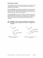
For 1/2" shank bits, insert threaded bit adaptor into the chuck assembly
and then insert bit into threaded collet (See Figure 20) and tighten the
collet with a wrench. Position the bit in the adapter as shown in Figure 22.
Verify that the collet is also securely tightened.
For 1/4" shank bits, insert bit into bit adapter and tighten setscrews with
supplied Allen wrench (See Figure 21). Position the bit in the adapter as
shown in Figure 22 and always make sure the setscrews are tight. For
long-term bit setup use a drop of permanent thread cement on the
setscrews.
//_
WARNING:
Failure to correctly
install the bit in the adapter
can result in injury, damage to the machine, or damage to the
workpiece.
j
Bit Adapter
FIGURE20: COLLET ARRANGEMENT
FOR1/2" SHANK BITS
Sears, Roebuck and Co.
CompuCarve
FIGURE21:
COLLET ARRANGEMENT
1/4"
TM
FOR
SHANK BITS
System (Rev 1.6) 09/27/06
Page 27
Proper Bit Installation
A
B
C
(I ncorrect)
(I ncorrect)
(Correct)
FIGURE22:
CORRECT
BIT ASSEMBLY
A
IS TOO LOW IN EXAMPLE
Approved
IS SHOWN IN EXAMPLE
C.
AND TWO HIGH IN EXAMPLE
THE
BIT
B.
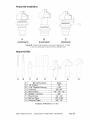
Bits
,ili
il
,ili
/
[
S'
k
A
D
#
A
B
C
D
E
F
G
H
E
Bit Family Name
1/8" Cutting
1/16" Tapered Carving
V-Groove
Round Nose
Straight- Jointing
Round-Over
Roman Ogee
Classical Ogee
FIGURE23:
Sears, Roebuck and Co.
CompuCarve
APPROVED
TM
F
G
H
Sizes
1/8"
1/16"
60 °, 90 °
1/8", 1/4", 1/2"
3/8"
1/4", 1/2"
1/8", 3/16"
3/8", 1/2"
ROUTER
BITS
System (Rev 1.6) 09/27/06
Page 28
Cocking the Quick Release Chuck
The quick release chuck must be cocked in order to install a bit. To cock
the chuck, press all the way up on the chuck release flange (See Figure
25) and release. The outer flange will snap up when the chuck is
prepared to receive the bit assembly. Any time difficulty is encountered
inserting a bit and adapter simply pull up on the flange to insure the chuck
is cocked.
Bit Assembly
Installation
When a carving function has been selected from the display menu, the
CompuCarve
will move the cutting head to the center of the machine and
prompt for the required bit.
Quick
Release
Chuck
FIGURE24:
QUICK RELEASE
CHUCK
To insert a bit: lift up on the front safety cover, cock the quick release
chuck, and press the bit assembly into the chuck until a slight snap is felt.
Close the cover and press the ENTER key. The machine will proceed
with measuring the bit and processing the selected task.
the
workpiece
and/oronly
damage
to the bit
CompuCarve
Be certain
to insert
the proper
requested;
may result from installing incorrect cutting bits.
All motors are disabled whenever the cover is open.
must be closed before the machine can proceed.
Sears, Roebuck and Co.
CompuCarve
TM
System (Rev 1.6) 09/27/06
machine to
damage
The cover
Page 29
Bit Assembly
Removal
To remove a bit quickly, a thumb should be placed on the Z-Truck Grip
Ridge (see Figure 25 below) and the Chuck Release Flange should be
pulled up while pulling lightly on the bit with the opposite, gloved hand.
WARNING:
Use caution to avoid being cut by the sharp
cutting edges of the router bit. Use caution if the bit has
recently been in use; it may be HOT and a glove will be
required to handle it.
FIGURE25:
QUICK RELEASE
CHUCK
FEATURES
Bit Removal
Tool
Alternately, the supplied bit
removal tool can be used to
extract the router bit as shown in
Figure 26 and 27. Slide the
removal tool under the release
iz
FIGURE26:
BIT REMOVAL
TOOL INSERTION
flange and into the adapter slot
and then lift the handle in a
gentle prying motion. The
removal tool straddles the bit
adapter to hold it and keep it
from falling as the bit is released.
The bit and its collet assembly
will drop out onto the removal
tool as it lifts the release flange.
After removing a bit using the
removal tool, the quick release
chuck may be left un-cocked.
To cock it, push the flange up on
the chuck to prepare for insertion
of another bit.
Lift
FIGURE27:
Sears, Roebuck and Co.
CompuCarve
TM
BIT RELEASE WITH TOOL
System (Rev 1.6) 09/27/06
Page 30
The CompuCarve
is a precision machine tool. With proper care and
maintenance it will provide long, reliable service.
,_
WARNING:
Always
unplug machine
before
attempting
troubleshooting
or maintenance
on the
machine.
any
Dust Removal: The CompuCarve
is designed to tolerate a
considerable amount of carving system dust, but to ensure proper
operation it should be kept free of debris as much as possible.
Periodically blow or vacuum out any dust or debris from the recesses
the unit.
of
Pitch Removal:
Pitch buildup is not a big problem, but should a
workpiece with a high content of pitch be carved there may be some
pitch deposits on the cutter bit and elsewhere.
This is easily removed
using mineral spirits.
The Muffler and Dust Collector Bag should be removed
out periodically to ensure a good airflow.
and cleaned
Lubrication:
Several areas of the CompuCarve
machine will require
occasional cleaning and re-lubrication.
It is recommended
that the
flexshaft be lubricated after every 20 hours of cut motor on time.
The flexshaft
cable should be cleaned and re-lubricated
from time to
time. The machine will notify the user when the flexshaft is due for
lubrication and give instructions on the material and procedure.
To
access the cable, first unplug the CompuCarve
machine from power.
Firmly grasp the flexshaft outer sheath where it is snapped into the
machine's cutting head and pull it free from the head. The cable is
contained within the sheath, and should slide out freely when
grasped between finger and thumb. Inspect the cable for debris and
clean with a lint free cloth if necessary.
After applying the machine
specified lubricant slide the cable back into its sheath. When near
full insertion, the cable may need to be carefully rotated with the
fingers to ensure that its square end engages correctly with the
cutting motor. Once the cable is fully inserted in the sheath, it can
once again be snapped into the cutting head. Rotate the bit chuck if
necessary to get the square end to engage with the chuck.
The patented quick release chuck's operation can be affected by
rust. Surface rust can cause the bit adaptors to stick in the chuck.
Periodically clean out dust from the chuck using compressed air
and/or a small stiff bristled brush. Once cleaned, re-lubricate the
chuck with multi-purpose
light oil (like 3-IN-ONE oil). Always try to
keep a thin film of oil on the chuck and the bit adaptors to deter rust,
to provide lubrication, and to help transfer heat between the bit
Sears, Roebuck and Co.
CompuCarve
TM
System (Rev 1.6) 09/27/06
Page 31
adaptor and the chuck assembly during heavy use. Avoid overlubricating the chuck as this will only attract dust and could result in
staining the workpiece.
The guide rods/rails upon which the cutting head assembly rolls
need to be kept free of cutting debris. They should be wiped or
blown off before carving a project, and wiped occasionally with a thin
coat of light oil for lubrication. If the rails are allowed to accumulate
dust and debris, the machine will halt during usage and an error
message will be seen on the display with a reminder to clean the
rails. Once they have been cleaned, pressing the ENTER key on
the keypad will resume operation.
The vertical guide rods at the corners of the machine also need to
be clean and rust free for smooth operation. A thin coat of paste
wax occasionally applied to the rods will help keep them free of rust
and will minimize accumulation of wood debris from machining
operations. The wax should be applied with a clean cloth, allowed
to dry, and then buffed off with a soft cloth to remove any excess.
Replacement Items: Occasionally, due to wear or accident, some
components of the machine will need replacement:
The flexshaft will periodically need to be replaced. The time period
will depend on the duration and type of use the machine has had.
The CompuCarve can detect when the flexshaft is going bad and
will prompt the operator to replace it. If the flexshaft is not replaced
and its condition degrades further, the CompuCarve will cease to
operate until it has been replaced.
o Replace dented or damaged bit adaptors.
o Use only correct factory supplied replacement set screws in the 1¼
inch bit adaptors.
o Belt replacement: The toothed belts used for various motion
functions are expected to last the life of the machine. If they are
damaged, they will require replacement at a Sears service center.
Traction belt replacement: The grit-faced traction used to grip the
workpiece and move it through the machine should last the
machine's entire operational life. Replacement for damaged belts
must be done at a Sears service center.
Accessories
cutting
bits,
CompuCarve
and Parts
Source:
Available
and user-replaceable
web
Sears, Roebuck and Co.
parts
accessories,
can be obtained
approved
through
the
site
CompuCarve
TM
System (Rev 1.6) 09/27/06
Page 32
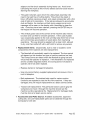
CUT DEPTH for any operation
not allow deeper operations.
"_" MAXIMUM
is 1.0 inch. The machine
will
"_" ALL MOTORS ARE DISABLED when the front safety cover is open.
The cover must be closed before the machine can proceed.
"_" USE A SUPPORT FOR LONG WORKPIECES.
To minimize the risk of
over stressing the machine, use sturdy roller stands (additional
accessory) for workpiece support when carving long workpieces more
than 36 inches in length.
"_'WHEN
LOADING THE WORKPIECE,
there are several critical checks to
make before proceeding.
o Do not attempt to load a workpiece that has a significant taper to the
sides. A tapered workpiece will bind between the sliding plate and the
squaring plate and will damage the traction drive.
o Do not attempt to load a workpiece that varies in thickness by more
than 1/16" along its entire length. Using a workpiece with a larger
thickness variation than 1'16" can lead to damage to the machine.
"_" MAKE SURE THAT
finishing carving. If
move up and down.
from the face of the
the front face of the
THE HEAD LOCKING LEVER IS RELEASED after
the locking lever is not released the head will not
The lever is in the locked position if it is rotated out
machine.
It is in the released position if it is flush to
head.
"_YTO AVOID SNIPE, use outfeed roller stands for long workpieces.
Any
workpiece over 3 feet long will require that additional stand-alone outfeed
rollers be used to support the workpiece.
Make sure the rollers are
adjusted properly to avoid letting the workpiece sag or rise up against the
upper rollers. Any uneven transition going on and off the rollers will be
seen in the finished carving, similar to snipe effects from a power planer.
"_'WHEN
CARVING LARGE PIECES, the CompuCarve
machine should
be secured to the bench for stability. Holes are provided in the four
corners to bolt the machine down.
"(_" USE ONLY QUALITY TOOLS.
Be sure cutters are sharp and not
damaged.
Use only approved cutting bits.
"_" FOR BEST CARVING RESULTS
o Always make sure the Board Tracking Sensor that contacts the
bottom of the workpiece has a smooth, even surface to follow. This
means that the bottom edge area of the workpiece adjacent to the
squaring plate is clean, smooth, and even for a width of at least 1/4
inch along the full length of the workpiece.
o Keep all vector cuts at lease 3/4" away from the left edge. This will
assure that the Board Tracking Sensor will remain in contact with the
board at all times.
Sears, Roebuck and Co.
CompuCarve
TM
System (Rev 1.6) 09/27/06
Page 33
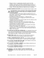
o Warped, bowed, or cupped pieces should be used only if this
condition is minor and if the Board Tracking Sensor can follow it. A
workpiece with slight cups or bows should be inserted curve down.
o Avoid creating very thin features that protrude from the surface of the
carving. Very thin features that are raised are prone to chipping.
"_'WHEN
CARVING
IN PLASTIC,
there are several
issues to keep in mind.
Carving plastics can be very hard on the machine if the proper
material is not used of if the chips are not regularly
removed
from the machine.
o Only Polycarbonate
or Cast Acrylic plastics are approved for use in
this machine. Most other common plastics melt during cutting and will
damage the machine if used.
o The maximum cut depth for plastics is .1 inches per pass.
o Plastic shavings are prone to clogging the machine and must be
vacuumed out regularly.
o If possible remove any thin protective plastic from the surface to avoid
wrapping it around the spinning bit.
o Because of the smooth slick nature of the plastic surface, the
workpiece must be mounted to a backing board so that the Board
Tracking Sensor will perform properly.
o Make sure that any hardware used to affix the plastic to the backer
board resides outside of the cutting area.
o If cutting in clear plastic the machine may have trouble locating the
edges at startup. To avoid this simply place masking tape along the
edges of the workpiece.
"(_" CLEAR DUST AFTER EACH OPERATION.
It is important that any dust
on or near the Squaring Plate and the Sliding Guide Plate be removed
before starting a cutting operation to ensure that the sensors can find the
board edges accurately.
A simple wipe will usually suffice.
"(_" MAKE TEST CUTS, when carving a new project test the project on
scrap wood to ensure that the settings produce desired results.
"_" SMALL WORKPIECES
MUST USE JIG. Any workpiece smaller than
1.5 inches wide x 0.25 inches thick x 7 inches long will require jigging.
"_'TO
LOCATE THE MACHINE RUN-TIME,
on the keypad to access the information.
'_,_tTO LOCATE THE SERIAL NUMBER,
the keypad to access the information.
"_'TO
LOCATE FIRMWARE VERSION,
the keypad to access the information.
use the Options shortcut
use the Options shortcut
use the Options shortcut
key
key on
key on
,¢.
\WARNING:
CUT ONLY WOOD, PLASTIC OR WOOD-LIKE
MATERIALS.
Do not cut metal, glass, stone, tile or any other hard
materials.
Sears, Roebuck and Co.
CompuCarve
TM
System (Rev 1.6) 09/27/06
Page 34
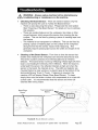
WARNING:
Always unplug machine before attempting
troubleshooting
or maintenance
on the machine.
any
Checking the Board Sensor: There are several reasons why the
machine will prompt the user to "Check the Board Sensor".
o There is dust obscuring the sensor. Please see the next section
titled "Cleaning of the Board Sensor" for details on how to address
this situation.
o
There are existing features on the workpiece, like holes or other
carved features, which prevent the sensor from tracking the top
surface. This can be fixed by placing a piece of masking tape over
the feature.
o
The material is too transparent or reflective. This can be fixed by
placing a piece of masking tape on the surface of the workpiece
along the line that the sensor traces while measuring.
This
generally requires placing tape across the width and length of the
workpiece.
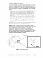
Cleaning of the Board Sensor:
From time to time the sensor that
locates and measures the workpiece can become obscured by dust.
The sensor system consists of an infrared LED and an infrared
detector. The board sensor works by reflecting infrared light off of the
board, and reading the intensity of the reflection. When the board is
underneath the sensor, the reflected intensity is high and when the
sensor is the board, the intensity is low. The LED and detector are
mounted behind a clear window in a plastic case at the bottom of the
Horizontal Moving Truck (Y-Truck).
If cleaning is required, the
machine LCD will display Please Clear Board Sensor. To clean,
simply blow onto the sensor window with compressed air or wipe with
a clean cloth.
It is recommended
that this sensor and mirror be
cleaned after every project.
!
Top Compression
Rollers
Board Edge
Sensor
.....
......
ii
,,
...........
FIGURE 28: BOARD SENSOR CLEANING
Sears,
Roebuck
and Co.
CompuCarve
TM
System
(Rev
1.6) 09/27/06
Page 35
Troubleshooting
the Board Sensor
If the board sensor error cannot be resolved by cleaning the sensor as
in the above steps you can further troubleshoot the problem. To check
the status of the board edge sensor, go to the Main Menu-OptionsSensor Check menu (Item 7). Use the arrow keys to find Board Sensor
on the bottom line of the display and press ENTER. Do the following
checks:
O
O
Load a board lower the head and check the reading displayed on
the LCD. The correct reading should be in the range of 150 to 170.
Check the reading displayed on the LCD when the sensor is not
over a board. The correct reading should be less then 10 and
ideally 0.
Raise the head, so that you can place your hand underneath the
board sensor. Use your hand to drive the Board Sensor reading to
go greater than 50. Quickly remove your hand from under the
sensor. You should see the reading drop immediately to the no
board reading. The correct reading should be less then 10 and
ideally 0.
If any of the checks fail, ensure the sensor is clear of dust and recheck.
If the operation does not improve, contact CompuCarve.
Vertical Lockup:
Cranking the head beyond its highest useable
height can result in it locking in a position where the head crank cannot
lower it. Releasing from this locked position it is very easy. The
threaded head screw needs to be manually turned and can be
accessed from the inside of the machine. On this head screw, just
above the traction belts, is a hole into which an Allen wrench or similar
tool can be inserted. Using the Allen wrench as leverage, turn the
head screw a clockwise direction to unlock it.
Hole
Head Screw
i!_i_iiii
Rotate
i
i
FIGURE29:
Sears, Roebuck and Co.
HEAD RELEASE PROCEDURE
CompuCarve
TM
System (Rev 1.6) 09/27/06
Page 36
Calibrating Machine Offsets: The "Calibrate Offsets" function is a
simple procedure to allow the user to fine-tune the CompuCarve
machine for improved accuracy.
To perform the offset calibration you
will need:
A board at least 2" wide by 10" long between 1/2" and 3/4" thick.
The CompuCarve
branded 3/8" Jointing Bit (using a nonCompuCarve
branded bit will affect accuracy).
The CompuCarve
sensor calibration will vary slightly depending on
the color and darkness of the material. If you tend to work in one
type of wood then best results will be realized by calibrating the
machine using that wood type. If you tend to carve in a variety of
woods, choose a wood for calibration that is in the middle of the
range of color and darkness.
For best results, you should choose a straight, flat board that has crisp,
clean corners, and ensure that the Jointing bit is in good shape. Begin
by measuring the thickness of the board you have chosen. Try to
measure to within at least 1/32" of the actual thickness.
Load the board in to the machine and select Options from the
CompuCarve
main menu by using the up/down arrows or pressing the
"0" on the keypad. Select item 6, Calibrate Offsets, from the Options
menu. You will be prompted for the thickness that you just measured,
key in the value and press ENTER. The machine will begin measuring
the board and then will prompt for the 3/8" Jointing bit. Load the bit as
normal and press ENTER. The machine will take a few more
measurements
and cut a slot into the board.
Once the slot is complete, the CompuCarve will begin alternating
between measurement and cuts along the two sides of the slot and the
two sides of the board. When the machine has completed the
calibration the new offsets will be stored into the machine and the LCD
will return to the Options menu. The entire process takes just a few
minutes. If the calibration fails, please see the entry entitled
Troubleshooting
the Board Sensor in the above paragraph.
Checking the Head Pressure:
Cranking the head down onto
workpiece assures that there is sufficient pressure to move the
workpiece in and out of the machine on the traction belt drive.
is not enough head pressure, the sensors that monitor whether
workpiece is inserted correctly will not operate properly.
If this
happens then the message "Please Insert Board " may persist
LCD.
Sears, Roebuck and Co.
CompuCarve
TM
System (Rev 1.6) 09/27/06
the
If there
the
on the
Page 37
Head
Top Compression
Rollers
FIGURE 30"
HEAD SHOWING
COMPRESSION
ROLLERS
Checking the head pressure is very easy using a standard bathroom
scale.
1. Before starting, make sure that the sliding plate is moved all the
way to the far side of the machine and is out of the way of the
scale.
2. Place the scale on the traction drive like you would a regular
workpiece.
Orient the scale so that the measurement display is
facing the keypad and position the top head rollers (mounted on
the underside of the head) directly over the scale footpads.
3. Crank the head down and make sure that the clutch clicks at least
five times to verify maximum loading.
4. Read the scale measurement
and repeat several times. The
proper head loading should be between 75 and 85 pounds.
If the head loading is not within these bounds the most likely caused by
insufficient lubrication of the four vertical corner posts or the two
vertical leadscrews.
Wipe all residue off these parts and apply a thin
film of White Lithium Grease to each. Crank the head up and down
several time so as to spread the grease evenly along the parts. If this
condition persists please contact CompuCarve
help services to
address the issue further.
Sears, Roebuck and Co.
CompuCarve
TM
System (Rev 1.6) 09/27/06
Page 38
iiiiiiiiiiiiiiiiii
Your
Home
iiiiiiiiiiiiiiiii
..................
HHHHHHHHH_
For repair -- in your home -- of all major brand appliances,
lawn and garden equipment, or heating and cooling systems,
no matter who made it, no matter who sold it!
For the replacement
owners
parts, accessories
and
m an asia that you need to do-it-you rself.
iiiiiiiiiiiiiiiiii
For Sears professional
installation
garage door openers
of home appliances
and items like
and water heaters.
1-800-4-MY-HOME
® (1-800-469-4663)
Call anytime, day or night (U.S.A. and Canada)
w ear co www ear
ca
iiiiiiiiiiiiiiiiii
..................
CCC::
OurHome
For repair of carry-in items like vacuums, lawn equipment,
And electronics, call or go on-line for the location of your nearest
Sears Parts & Repair Center.
1-800-488-1222
Call anytime,
day or night (U.S.A. only)
www.sears.com
To purchase
a protection
1-800-827-6655
agreement
(U.S.A.)
on a product serviced
1-800-361-6665
by Sears:
(Canada)
iiiiiiiiiiiiiiiiii
Pard pedir servicio de reparaciCn
a domicilio, y pard ordenar piezas:
1-888-SU-HOGAR su
(1-888-784-6427)
Au Canada pour service
en frangais:
1-800-LE-FOYER
(1-800-533-6937)
www.sears.ca
® Registered Trademark / TM Trademark / SM Service Mark of Sears, Roebuck and Co.
® Marca Registrada / TM Marca de Fabrica / SM Marca de Servicio de Sears, Roebuck and Co.
MCMarque de commerce / SM Marque deposed de Sears, Roebuck and Co.
)
Mc